


ADJUSTING INSTRUCTIONS / ILLUSTRATED PARTS LIST
63900 STREAMLINED
HIGH SPEED NEEDLE FEED TOP AND BOTTOM ROLLER FEED LOCKSTITCH MACHINES
MANUAL NO. PT9636
STYLES
63900AM
63900AML
63900AT
63900AW
63900AAE
REV.08/31/98
CONTENTS |
|
•PREFACE ............................................................................................................................................................... |
4 |
•SAFETYRULES ........................................................................................................................................................ |
5 |
•IDENTIFICATION OF MACHINES ........................................................................................................................... |
6 |
•CLASS DESCRIPTION ........................................................................................................................................... |
6 |
•STYLEOFMACHINES ............................................................................................................................................ |
6 |
•ILLUSTRATIONS ...................................................................................................................................................... |
6 |
•ILLUSTRATIONS(CONT.) ....................................................................................................................................... |
7 |
•IDENTIFYINGPARTS .............................................................................................................................................. |
7 |
•NEEDLES ................................................................................................................................................................ |
7 |
•TABLEBOARD ........................................................................................................................................................ |
8 |
•BOBBIN WINDER ................................................................................................................................................... |
8 |
•BELTS ..................................................................................................................................................................... |
8 |
•LUBRICATION........................................................................................................................................................ |
9 |
•RECOMMENDED OIL ........................................................................................................................................... |
9 |
•OIL GAUGE .......................................................................................................................................................... |
9 |
•SELF-PRIMINGHEADOILSIPHON ...................................................................................................................... |
10 |
•INSTALLING AND MAINTENANCE OF OIL SIPHON ............................................................................................ |
10 |
•THREAD ............................................................................................................................................................... |
11 |
•REMOVING THE BOBBIN CASE .......................................................................................................................... |
11 |
•WINDING THE BOBBIN ....................................................................................................................................... |
11 |
•THREADINGTHEBOBBINCASE .......................................................................................................................... |
11 |
•THREADING THE BOBBIN CASE (CONT.) ........................................................................................................... |
12 |
•REPLACINGTHEBOBBINCASE .......................................................................................................................... |
12 |
•INSERTINGTHENEEDLE ...................................................................................................................................... |
12 |
•THREADINGTHENEEDLE .................................................................................................................................... |
12 |
•PREPARATIONFORSEWING .............................................................................................................................. |
12 |
•TENSIONS ............................................................................................................................................................ |
12 |
•BOBBINTHREADTENSION .................................................................................................................................. |
12 |
•BOBBINTHREADTENSION(CONT.) ................................................................................................................... |
13 |
•NEEDLETHREADTENSION .................................................................................................................................. |
13 |
•CHANGINGTHESTITCHLENGTH ....................................................................................................................... |
13 |
•TIMINGTHENEEDLEFEEDWITHTHECONTINUOUSTURNINGROLLERFEED .................................................... |
14 |
•PRESSUREONMATERIAL .................................................................................................................................... |
14 |
•SETTINGTHENEEDLEBARTOHEIGHT ................................................................................................................ |
14 |
CONTENTS(CONT.) |
|
•TIMING THE HOOK ............................................................................................................................................. |
15 |
•NEEDLEGUARDINSTRUCTIONS ......................................................................................................................... |
15 |
•NEEDLEGUARDINSTRUCTIONS(CONT.) .......................................................................................................... |
16 |
•HOOK LUBRICATION .......................................................................................................................................... |
16 |
•PRESSERBARGUIDE ........................................................................................................................................... |
16 |
•PRESERBARCONNECTION ............................................................................................................................... |
16 |
•TENSIONASSEMBLYADJUSTMENT ..................................................................................................................... |
17 |
•TENSIONRELEASE ............................................................................................................................................... |
17 |
•THREADCONTROL ............................................................................................................................................. |
17 |
•THREAD CONTROL (CONT.) .............................................................................................................................. |
18 |
•BOTTOM COVER ................................................................................................................................................ |
18 |
•HOOK SHAFT ...................................................................................................................................................... |
18 |
•HOOK SHAFT (CONT.) ........................................................................................................................................ |
19 |
•REMOVAL OF OILING DEVICE .......................................................................................................................... |
19 |
•REASSEMBLYOFOILINGDEVICE ...................................................................................................................... |
20 |
•REASSEMBLY OF OILING DEVICE (CONT.) ........................................................................................................ |
21 |
•UPPERMAINSHAFT ............................................................................................................................................ |
21 |
•UPPER MAIN SHAFT (CONT.) ............................................................................................................................. |
22 |
•HANDWHEEL ...................................................................................................................................................... |
22 |
•HANDWHEEL (CONT.) ........................................................................................................................................ |
23 |
•ATTACHMENTS ................................................................................................................................................... |
23 |
•NEEDLEHOLEINSERT .......................................................................................................................................... |
23 |
•MAINFRAME, BUSHING, OIL GAUGE HEAD OIL SIPHON AND MISCELLANEOUS OILING PARTS .................... |
25 |
•MAINFRAME, BUSHING, OIL GAUGE HEAD OIL SIPHON AND MISCELLANEOUS OILING PARTS .....(CONT.) 27 |
|
•MAINFRAMEMISCELLANEOUSCOVERSANDNEEDLETENSIONPARTS ......................................................... |
29 |
•MAINFRAMEMISCELLANEOUSCOVERSANDNEEDLETENSIONPARTS(CONT.) .......................................... |
31 |
•MAIN AND HOOK DRIVE SHAFTS, NEEDLE BAR AND FOOT LIFTER MECHANISM ............................................ |
33 |
•NEEDLEFEEDDRIVINGPARTS ............................................................................................................................ |
35 |
•PRESSERFEET,PRESSERBAR,TOPFEEDROLLERMECHANISMANDATTACHMENTS ....................................... |
37 |
•PRESSERFEET,PRESSERBAR,TOPFEEDROLLERMECHANISMANDATTACHMENTS ....................................... |
39 |
•ROTATING HOOK ASSEMBLY AND HOOK OILING PARTS ................................................................................ |
41 |
•FEEDROLLERDRIVINGPARTS ............................................................................................................................ |
43 |
•FEEDROLLERDRIVINGPARTS(CONT.) ............................................................................................................. |
45 |
•BOBBINWINDERANDMISCELLANEOUSACCESSORIES .................................................................................. |
47 |
•NUMERICALINDEXOFPARTS ............................................................................................................................ |
48 |
•NUMERICALINDEXOFPARTS ............................................................................................................................ |
49 |
•NOTES ................................................................................................................................................................. |
50 |
•NOTES ................................................................................................................................................................. |
51 |

Manual No. PT9636 Illustrated Parts List for 63900 Series Machines
First Edition Copyright 1997
By
Union Special Corporation Rights Reserved In All Countries
Printed in U.S.A. October 1997
PREFACE
This parts manual has been prepared to assist you in locating individual parts or assemblies on 63900 Series machines.
It is the desire of Union Special that each machine run at its optimum performance. Parts listed in this manual are designed specifically for your machine and are manufactured with utmost precision to assure long lasting service.
This manual has been comprised on the basis of available information. Changes in design and/or improvements may incorporate a slight modification of configuration in illustrations or part numbers.
On the following pages are illustrations and terminology used in describing the parts used on 63900 Series machines.
4

SAFETYRULES
1.Before putting the machines described in this manual into service, carefully read the instructions. The starting of each machine is only permitted after taking notice of the instructions and by qualified operators.
IMPORTANT! Before putting the machine into service, also read the safety rules and instructions from the motor supplier.
2. Observe the national safety rules valid for your country.
3. The sewing machines described in this instruction manual are prohibited from being put into service until it has been ascertained that the sewing units which these sewing machines will be built into, have conformed with the EC Council Directives (89/392/EEC, Annex II B).
Each machine is only allowed to be used as foreseen. The foreseen use of the particular machine is described in paragraph “STYLES OF MACHINES” of this instruction manual. Another use, going beyond the description, is not as foreseen.
4. All safety devices must be in position when the machine is ready for work or in operation. Operation of the machine without the appertaining safety devices is prohibited.
5.Wear safety glasses.
6.In case of machine conversions and changes all valid safety rules must be considered. Conversions and changes are made at your own risk.
7. The warning hints in the instructions are marked with one of these two symbols:
8.When doing the following the machine has to be disconnected from the power supply by turning off the main switch or by pulling out the main plug:
8.1When threading needle(s), looper, spreader etc.
8.2 When |
replacing any |
parts such as needle(s), presser foot, throat plate, looper, spreader, feed |
dog, |
needle guard, |
folder, fabric guide etc. |
8.3When leaving the workplace and when the workplace is unattended.
8.4When doing maintenance work.
8.5 When using clutch motors without actuation lock, wait until the motor is stopped totally.
9.Maintenance, repair and conversion work (see item 8) must be done only by trained technicians or special skilled personnel under consideration of the instructions.
10. Any work |
on the electrical equipment must be done by an electrician or under direction and supervision |
of special |
skilled personnel. |
11.Work on parts and equipment under electrical power is not permitted. Permissible exceptions are described in the applicable sections of standard sheet DIN VDE 0105.
12.Before doing maintenance and repair work on the pneumatic equipment, the machine has to be disconnected from the compressed air supply. In case of existing residual air pressure, after disconnecting from compressed air supply (i.e. pneumatic equipment with air tank), the pressure has to be removed by bleeding.
5

IDENTIFICATION OF MACHINES
Each UNION SPECIAL machine is identified by a style number, which is stamped into the style plate affixed to the middle of the machine under the tension assembly. The serial number is stamped into the serial number plate affixed to the right rear base of the machine.
CLASS DESCRIPTION
High speed streamlined long arm needle feed lockstitch machines. one needle, light, medium and heavy duty, continuous running roller feed, rotary hook, horizontal hook shaft, gears for changing stitch length, slot segment for adjusting needle feed, 1 1/4 inch needle bar travel, one reservoir enclosed automatic lubrication system, head oil siphon, adjustable hook oil control, needle bearing for take-up lever and needle bar driving link, needle feed timing on upper shaft, maximum work space to right of needle bar 8 inches.
STYLE OF MACHINES
63900AM For making 3/8 on 1/2 inch turned down hem on legs of overalls, coveralls, and dungarees. Seam Specification 301-EFb-1 inverted, Specify size of hem. Maximum recommended speed 5200 R.P.M.
63900AML Same as 63900AM except includes a hook with 52% greater bobbin capacity to reduce frequency of bobbin changes.
63900AT For making a 1/2 or 2 1/2 inch hem turned by hand on children's wear, men's dress pants, semi-dress pants and work pants. Sewn when garment reaches machine inside out. Seam Specification 301EFb-1 or EFa-1. Maximum recommended speed 5200 R.P.M.
63900AW For top stitching waistbands on twill and woolen pants. Machine equipped to sew over belt loops. Fitted with cloth plate extension. Seam Specification 301-SSa-1. Maximum recommended speed 5200 R.P.M.
63900AAE Same as Style 63900AW, except fitted with spring guide keel on presser foot in line with centerline of needle hole.
ILLUSTRATIONS
This manual has been arranged to simplify ordering repair parts. Exploded views of various sections of the mechanism are shown so that the parts may be seen in their actual position in the machine. On the page opposite the illustration will be found a listing of the parts with their part numbers, description and the number of pieces required in the particular view being shown.
Numbers in the first column are reference numbers only, and merely indicate the position of the part in the illustration. The reference number should never be used in ordering parts. Always use the part number listed in the second column.
Component parts of sub-assemblies which can be furnished for repairs are indicated by indenting their |
|||
descriptions |
under the description of the main sub-assembly. As an example |
refer to the following text. |
|
18. |
29126EL |
Needle Feed Driving Eccentric and Connecting Rod Assembly ................................. |
1 |
19. |
22894J |
Set Screw .................................................................................................................. |
2 |
6

ILLUSTRATIONS (CONT.)
When a part is common to all machines covered in this manual, no specific usage will be mentioned in the description. However, when the parts for the various machines are not the same, the specific usage will be mentioned in the description and, if necessary, the difference will be shown in the illustration.
*Ref. No. showing no Part No. is for location only. Part is not for sale separately.
A numerical index of all the parts shown in this manual is located at the back. This will facilitate locating the illustration and description when only a part number is known.
IDENTIFYING PARTS
Where construction permits, each part is stamped with its part number. On some of the smaller parts and on those where construction does not permit, an identification letter is stamped in to distinguish the part from similar ones.
PLEASE NOTE: Part numbers represent the same part, regardless of which manual |
they appear. On all |
||
orders please |
include part |
number, name and style of machine for which the part |
was ordered. |
For optimum |
performance |
use only genuine Union Special replacement parts. |
|
NEEDLES
Each needle has both a type and size number. The type number denotes the kind of shank, point, length, groove, finish and other details. The size number, stamped on the needle shank, denotes the largest diameter of the blade measured between the shank and the eye. Collectively, the type number and size number represent the complete symbol which is given on the label of all needles packed and sold by Union Special.
TYPE |
|
|
DESCRIPTION |
|
180 GYS |
Round |
shank, |
round point, lockstitch, short length ball eye single groove, struck |
groove, deep |
|
spot, chromium plated - sizes 075/029, 080/032, 090/036, 100/040, 125/049, 140, 054, 150/060. |
|||
180 GWS |
Round |
shank, |
round point, lockstitch, short length, oversize ball eye, single groove, struck |
|
|
groove, |
deep |
spot, chromium plated - sizes 090/036, 100/040, 110/044, 125/049, |
140/054. |
When changing the needle, make sure it is fully inserted in the needle holder before the screw is tightened.
When ordering needles, please use the complete type and size numbers as printed on the package to ensure prompt and accurate processing of your order. A complete order should read as follows: "100 needles, type 130 GS, size 125/049".
7

TABLEBOARD
The tableboard can now be mounted on the pedestal using four screws, adjusting the nuts so the top of the tableboard is flush with the top of the machine bed plate.
BOBBIN WINDER
The bobbin winder should be secured to the table top so that its pulley will be located directly in front of the sewing machine belt and will bear against the belt when in operation. The base of the winder has two elongated attaching holes, which allow the mechanism to be moved closer to or farther away from the belt as needed. The pulley of the winder, when in operation, should exert only enough pressure against the belt to wind the bobbin. Regulation and operation of the bobbin winder is described under "Winding The Bobbin", under "Instructions For Operator's".
BELTS
These machines are equipped to use either #1 "Vee" or round belts.
Fig. 3
8

LUBRICATION
CAUTION! Oil has been drained from the main reservoir before shipment and the reservoir must be filled before starting to operate.
Lubricate machine thoroughly, in accordance with instructions which follow, and run slowly for several minutes to distribute the oil to the various parts. Full speed operation can then be expected without d a m a g e .
RECOMMENDED OIL
Use a stainless water-white straight mineral oil of a Saybolt viscosity of 90 to 125 seconds at 100° Fahrenheit in the main reservoir. This is equivalent to Union special specification No. 175. Fill main reservoir at plug screw (B, Fig. 3) and check oil level at gauge (C): oil is at maximum level when needle is in yellow band marked "FULL". Oil should be added when needle is in yellow band marked "LOW".
It is recommended that a new machine, or one that has been out of service for an extended period, be lubricated as follows: Remove the head cover and directly oil the bearings of the needle bar link, the takeup and its lever and needle bar. Replace end cover, as no further hand oiling will be required.
Oil may be drained from main reservoir by removing plug screw (D, Fig. 3).
OIL GAUGE
The oil gauge is set at the factory to show the proper oil level in the reservoir. Should and adjustment become necessary, the following steps should be followed:
1. Place the machine upright on a level table or bench.
2.Remove the reservoir plug screw (located below the handwheel and near the bottom of the machine) .
3.Oil should be added or removed so that the oil level is approximately 1/8 inch below the bottom edge of the hole.
4.Loosen lock nut (E, Fig. 3) on the calibrating screw (F), and turn screw left or right so the gauge needle rests on the yellow band marked "FULL" on gauge (C).
5.Tighten lock nut and replace plug screw.
9

SELF-PRIMING HEAD OIL SIPHON
Class 63900 machines are equipped with a self-priming head oil siphon. When the machine is started, oil splashes on the priming cup felt, filters through the felt and trickles down the vertical oil tube, thus priming the siphon. Once the prime is established, it is maintained, unless the felt is removed. The siphon operates twenty-four hours a day, removing oil at the rate of six to twelve drops per minute, which, of course, far exceeds the rate at which oil collects in the head.
INSTALLING AND MAINTENANCE OF OIL SIPHON
A newly installed siphon starts its action within three to five minutes after the machine is operating. However, it may be twenty minutes or so before all the air is removed from the line and the siphon is in full operation. Within an hour, there should be a distinct reduction of the oil in the head sump. If the siphon does not function, determine if the siphon intake tube, located in the head, is inserted in the felt block and that the plastic tube is connected at both ends. If the above two items do not correct the siphon, replace the siphon felts as described below.
The felt in the priming cup is designed for a specific purpose. This felt, No. 666-237, is to meter the flow of priming oil and to prevent the entrance of air. The felt also acts as a filter and keeps the siphon clear of lint.
If the priming cup felt and the intake felt (666-214) becomes contaminated with an excessive amount of lint, it may be necessary to replace the felts. The priming cup felt is replaced by removing access plug at back of machine and replacing felt 666-237. For the best initial self-priming condition, the felt of the siphon should be installed dry. The intake felt is replaced by removing the end cover.
However, if for some reason the priming cup felt has been oiled before installing, the siphon may fail because air is trapped in the felt. As a precaution, remove felt from cup. Then, while squeezing the felt between the fingers, saturate it well with oil. In other words, squeeze out the air and replace it with oil. This prevents the trapping of air, and no trouble should be experienced when starting the siphon.
10
|
|
|
THREAD |
While the direction of the twist |
in the bobbin thread is immaterial, the direction of the hook rotation favors |
||
the use of a left twist thread in the needle. |
To determine the direction of twist, grasp a short length of thread |
||
between thumb and |
forefinger of each hand. Turn the thread away from you with your right hand. If the |
||
strands unwind, it is |
a left twist, |
if not, it is |
a right twist. |
REMOVING THE BOBBIN CASE
To remove the bobbin case, turn handwheel in operating direction until needle reaches its highest position. Using the left hand, reach in under the throat plate at left end of machine, open the bobbin case latch (A, Fig. 5), and pull the bobbin case out of the sewing hook.
Opening the latch retains the bobbin in the case. When the latch is closed, the bobbin is released and can readily be removed.
WINDING THE BOBBIN
Thread the bobbin winder by leading the thread from the supply down through the eyelet (A, Fig. 6), down between the tension discs, and under the tension post. Press an empty bobbin on the winder shaft (B), up to the stop, wind the end of thread around the bobbin a few turns in a clockwise direction and press downwardly on hand lever (D) until pulley is moved into contact with machine belt, and is locked in that position. When the machine is operated, the bobbin will be rotated and filled until the thread engages the automatic throw-out member, which disengages the pulley. The extent to which the bobbin is filled can be varied by regulating the screw (C).
The tension post bracket is mounted on the winder base, and can be shifted from left to right by loosening screw (E) so that any tendancy of the bobbin to wind unevenly may be readily corrected.
The purpose of the bobbin winder is to assure an operator of a full bobbin at all times. When the bobbin in the machine is used up, replace it with the full one, and begin to wind the empty on immediately. Bobbins can be rewound while the machine is sewing.
THREADING THE BOBBIN CASE
The bobbin case (A, Fig. 7) should be held between the thumb, forefinger and second finger of the LEFT hand.
The bobbin (B) itself should be held between the thumb and forefinger of the right hand with thread coming off the bottom of the bobbin.
11
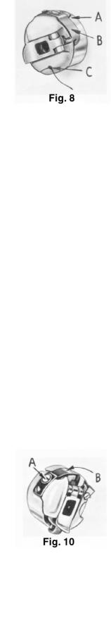
THREADING THE BOBBIN CASE (CONT.)
Place the bobbin in the bobbin case. In one continuous motion, with thumb and forefinger of right hand, draw the bobbin thread through diagonal slot in bobbin case (A, Fig. 8) under the tension spring (B) and into self threading slot (C) on case. Mote direction of the rotation of the bobbin as the end of the thread is pulled when looking at the bobbin case from the back. The bobbin should rotate counterclockwise.
REPLACING THE BOBBIN CASE
|
|
|
|
Have the needle bar at tis highest position, allow about two and one |
half inches of |
|||||
|
|
|
|
thread to |
hang |
free. |
The bobbin case latch should be opened with |
the |
left hand, |
|
and |
by |
reaching |
under |
the |
throat |
plate |
and through the bed plate extension, it should be placed |
part way |
||
into |
the |
sewing |
hook. |
the |
latch |
should |
then |
be released and bobbin case into position. |
|
|
INSERTING THE NEEDLE
Insert the needle into the needle bar as far as it will go, with the spot (sometimes called scarf) towards the right, facing the handwheel. Tighten the nut securely.
The cross hole in the needle bar, about 1/4 inch from the end (A, Fig. 9), is to show the operator when the needle has been inserted as far as it will go, and to provide a means for cleaning the accumulated lint from needle hole so the needle will seat properly.
THREADING THE NEEDLE
Threading diagram (Fig. 3) shows the places where the needle thread passes. Please note that the needle thread passes through the needle eye from left to right.
PREPARATION FOR SEWING
With your left hand, hold the end of the needle thread, leaving it slack, and turn the handwheel in operating direction until the needle moves down and up again to its highest position. Pull up the needle thread and the bobbin thread will come up with it, through the needle hole in the throat plate. Draw both threads under the presser foot.
TENSIONS
A perfect stitch is one in which the needle thread and bobbin thread are locked together in the center of the material being sewn. A stitch of this kind is secured by regulating the tensions on both threads.
BOBBIN THREAD TENSION
The tension on the bobbin case is applied by means of a set screw (A, Fig. 10) which regulates the tension spring (B). The tension on the spring is correct when it is just sufficient to hold the bobbin case and bobbin suspended by the bobbin thread. The thread should not be
in the eyelet for this adjustment check.
12
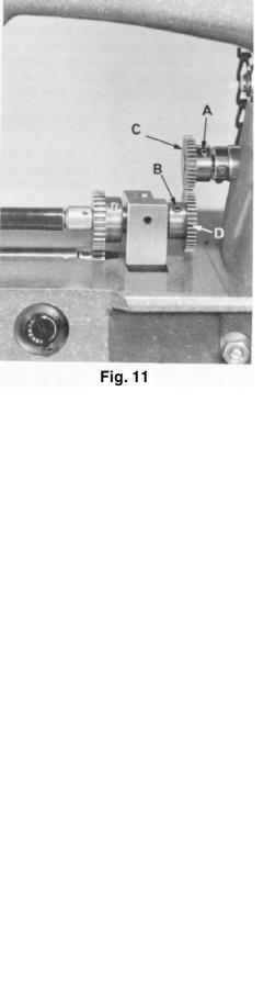
BOBBIN THREAD TENSION (CONT.)
Remove the bobbin case from its holder and turn set screw in spring in a clockwise direction to apply more tension or counterclockwise to release tension.
When the bobbin thread tension is correct, it rarely becomes necessary to make any changes as varying the needle thread tension will usually attain a good stitch.
NEEDLE THREAD TENSION
The needle thread tension is varied by turning the tension regulating nut (G, Fig. 3). Turning the nut in a clockwise direction increases the tension, while counterclockwise decreases it. This should not be done when the presser foot is in its raised position, but is generally done while the machine is sewing on a piece of scrap material.
CHANGING THE STITCH LENGTH
Unless otherwise specified machine Styles 63900AM, AML and AT will |
|
||
be equipped with upper feed regulator gear No. 63949-39 and |
|
||
lower feed regulator gear No. 63949-41 to produce 9 stitches per |
|
||
inch (S.P.I.), while Styles 63900AW, and AAE will be equipped with |
|
||
upper feed regulator gear No. 63949-37 and lower feed regulator |
|
||
gear No. 63949-43 to produce 10 S.P.I. |
Other |
gears are available |
and may be ordered separately. Refer |
to "Gear Chart" below for the gears necessary |
to produce S.P.I. other than previously described. |
||
|
GEAR CHART |
|
|
S.P.I. |
UPPER GEAR |
LOWER GEAR |
|
6 |
63949-47 |
63949-33 |
|
7 |
63949-44 |
63949-36 |
|
8 |
63949-41 |
63949-39 |
|
9 |
63949-39 |
63949-41 |
|
10 |
63949-37 |
63949-43 |
|
11 |
63949-36 |
63949-44 |
|
12 |
63949-33 |
63949-47 |
|
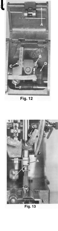
To remove feed regulators gears, first remove feed drive gear cover located under arm of machine. Now loosen screws (A and B Fig. 11) and slide gears (C and D) off their respective shafts. Replace with gears for desired stitch length. After new gears have been installed be sure to reset needle feed stitch length to agree with the continuous turning roller feed.
13
TIMING THE NEEDLE FEED WITH THE CONTINUOUS TURNING ROLLER FEED
Open top cover (A, Fig. 12) in the head of the machine and loosen needle frame drive segment locking nut (B). Set connection stud (C) to point of maximum number of stitches per inch of needle feed. This would locate the connecting arm at letter "S".
Loosen two set screws on the needle frame drive eccentric (D). Rotate the handwheel until the needle bar is at the bottom of its stroke. Rotate the eccentric only, until the timing line (2) on the connecting arm and the eccentric hub coincide. Tighten all screws, on every thick seams that cause thread breakage advance needle feed timing slightly.
Rotate handwheel until the needle bar is at bottom of its stroke. The needle bar should be vertical. If it is not, loosen clamp screw (F) and move needle bar frame forward and backward until bar is vertical. Tighten screw, making sure allside play is removed from between the needle bar frame and the segment.
To set needle feed with roller feed loosen needle frame drive segment locking nut. Set connection toward higher designated letter on segment for approximate setting. Vary the needle travel so as to obtain the least amount of needle deflection when the needle enters or leaves the thickest section to be sewn.
PRESSURE ON MATERIAL
The presser spring (A, Fig. 17) should exert only enough pressure on the feed rollers to make the work feed uniformly. To increase the pressure on the preser foot, turn presser spring regulator (B, Fig. 17) in a clockwise direction.
Turning the regulator counterclockwise decreases the pressure.
SETTING THE NEEDLE BAR TO HEIGHT
The three lines engraved on the needle bar are used in setting needle bar to height, and are referred to as TIMING LINES.
Th middle and lower lines are used for Styles 63900M, T, and W. For 63900AM, AML, AAE, AT and AW the upper and middle lines are used.
When the needle bar is at its lowest position the upper timing line (B, Fig. 13) should be EVEN with the lower edge of the lower needle bar frame
(A).
To change the position |
of the needle bar, turn handwheel until the bar |
is at its lowest position. |
Then, loosen the clamp screw (C) and move the |
bar to the proper timing line. Keeping the needle bar line at its lowest position, tighten the screw securely.
14

TIMING THE HOOK
Remove throat plate. Loosen three set screws (A) in the hook, and |
||||
hold the hook and the bobbin case holder in such a position as to |
||||
prevent interference with the needle. Turn handwheel in operating |
||||
direction until the needle bar |
is at its lowest position, and continue |
|||
to turn the handwheel until the needle is ascending and the middle |
||||
timing make (Fig. 13) used in setting the needle bar is even with the |
||||
lower edge of the needle bar frame (A). |
|
|
|
|
Turn the hook on the shaft until the point of the hook is even with the |
||||
center of the needle and as close to the needle as possible without |
||||
deflecting it. A spacing of .003 to .005 inch between the needle and |
||||
the point of the hook is satisfactory. With the hook in this position, |
||||
tighten the set screw opposite the hook point securely. Then, |
||||
tighten the two remaining screws securely, and |
recheck |
the |
timing |
|
of the hook with the needle. |
At the hook timing |
position |
the |
top of |
the |
eye of the needle should be about 1/64 inch below the bottom |
of |
the hook point. |
Replace throat plate, allowing 1/32 inch clearance between the outside edge of projection and the inside edge of bobbin case recess.
NEEDLE GUARD INSTRUCTIONS
In the hook, at the Fig. 15) is found a
right side of the needle hole in bobbin case holder (B, needle guarding surface (A, Fig. 15).
The purpose of this guarding surface is to prevent the hook point (C) from coming in contact with needle (D) at loop-taking time, should the needle be deflected toward the hook point. The needle guard will deflect the needle slightly when needle is at bottom of its vertical travel if the hook is properly timed. (At loop-taking time there should be little or no deflection of needle by the needle guard.)
For additional needle clearance, especially with use of larger needles, removal of some needle guarding surface may necessary.
Before metal removal from the guarding surface all related settings should be checked as follows:
1. See that the needle bar is set to correct height.
2.Check for proper hook timing.
3.Rotate the handwheel in operating direction by hand. Check for excessive needle deflection beyond what is
cited on preceding page as a desirable condition.
4. |
If needle deflection is |
excessive, follow |
steps (A) and (B) |
|
b e l o w . |
|
|
|
( A ) Remove bobbin |
case holder from |
hook. |
(B)Remove excess metal from the needle guarding surface. This may be done by using a diamond file
No. TT60 or fine emery cloth (#320), with one end secured to the bench, and rubbing the guarding surface back and forth until sufficient metal is removed. When metal is being removed from needle guarding surface, the bobbin case holder should be reinserted frequently and tested until proper needle guarding is obtained.
15

|
NEEDLE GUARD INSTRUCTIONS (CONT.) |
CAUTION! |
Damage to the hook point may result if too much metal is removed from the needle guarding |
|
surface. |
The bobbin case holder should be thoroughly cleaned before reassembly into the hook base.
When altering needle guarding surface, it is suggested that the hook NOT BE REMOVED or disturbed from its timed position.
The bobbin case holder only may be removed by removing gib screws and gib and pulling on bobbin case stem as the handwheel is rocked backward and forward slightly.
|
|
HOOK LUBRICATION |
CAUTION! |
Do not |
run the machine without the bobbin case in the |
|
hook as |
hook damage may result. |
With the bobbin case in hook, run machine for a full minute. Place a piece of white paper directly under the hook and continue running the machine. After about five seconds, remove the paper and a definite and distinct pattern of oil spots should be observed.
Should more or less oil be required, turn oil control adjusting shaft (H, Fig.
3), |
located on the front of the machine just blow the cloth |
plate |
surface, |
in |
direction of the change required. After a change in the |
hook |
oil flow, |
the machine should be run about one minute before checking for the desired oil flow.
PRESSER BAR GUIDE
When locating presser bar guide (C, Fig. 17) presser foot must rest directly against throat plate. Proper setting of guide is 5 3/64 inches between underside of presser bar guide and the top of throat plate (Fig. 17). To obtain this setting, remove pressure from the presser spring (A) and loosen set screw (D). Tap on presser foot to insure it is down against throat plate. Set guide to the 5 3/64 inch dimension, center foot by turning it so needle enters the middle of its slot and retighten screw (D). Apply pressure to top
feed roller by turning regulator (E) clockwise.
Set needle thread pull-up bracket (F) so that underside of wire is 4 5/8 inches above throat plate (Fig. 17).
PRESER BAR CONNECTION
Presser bar conection (G, Fig. 17) should be set about 1/16 inch below prese bar guide (C). Accomplish this by loosening lick nut (A, Fig. 16), and relocating stop screw (B) on lifter lever bell crank (C), located at the back of machine, under bed plate. turning stop screw to right or left, properly sets presser car connection. Tighten lock nut (A) to lock stop screw.
16
 Loading...