


VF-A5
Table of contents
 Loading...
TOSHIBA
E6580516
High-Performance Inverter
Instruction Manual
TOSVERT VF-A5
200V
400V
1. Make sure that this Instruction Manual is delivered to the end
user of the inverter unit.
2. Read this manual before installing or operating the inverter
unit, and store it in a safe place for reference.
0.4
0.75
--55kW
~75kW
NOTICE
TOSHIBA CORPORATION
© 1994
Ver. no-'

Safety Precautions
This inverter is for driving a 3-phase motor, and must not be used for other applications.
[I] Always observe the following items to prevent electrical shock.
1. Do not touch charged parts such as the terminal block while the CHARGE lamp is lit. A charge will still
be present in the electrolytic capacitors, and therefore, touching these areas may result in an electrical
shock. Always turn the inverter’s input power off before wiring the motor terminals. Walt at least five
minutes after the "CHARGE' lamp has gone out, and then confirm that the capacitors have fully
discharged by using a tester, etc., that can measure high-voltage DC.
2. Do not touch or insert a rod or any other item into the
inverter while power is applied (there are high voltage areas
on the PCB), as this may lead to electrical shock or inverter
damage.
(When operating with the cover removed, charged areas will
be exposed, so always install the unit inside a panel so that
it cannot be easily touched.)
Never attempt to modify the inverter unit.
3. Ground the unit’s G/E terminal and the motor. (Electric
shock may occur due to leakage currents.)
[n] Retry function
1. This inverter has a "retry function" that automatically resets the unit when a fault trip occurs. Observe the
following points when this function is selected.
Even if the inverter has fault tripped, take care to not get caught in the motor or equipment. When the
"retry function" is selected, the inverter will automatically start after the designated time. (Refer to page
78.)
Take special care when an overload trip occurs, as the "retry function" may activate after a delay of up
to 5min.
[m] Observe the following points to prevent fire.
->/7
Ijili
'I
1111
llll
L=y
Control section
(W/hen cover is removed)
/
High voltage area
1. Confirm the inverter’s rating nameplate, and connect a 3-phase input power source within the rated range
to the RA.1, S/L2, and TA- 3 power source terminals.
If an Incorrectly-rated power source is connected to the inverter, such as when a 400V power source is
connected to a 200V inverter, the inverter’s internal components may explode.
2. No fuse is contained in the inverter, so instail a suitable non-fuse breaker (MCCB) on the inverter’s input
power source.
(Refer to Table 5-1 on page 14 for Examples of selecting equipment for wiring.)
[IV] Refer to the following chapters for other precautions.
Chapter 1 Acceptance Inspection and Precautions
Chapter 2 Installation Precautions Page 2
Chapter 4 Cperation Precautions Page 5
Chapter 5 Wiring Precautions Page 9
Chapter 12 Maintenance and Inspection Page 102
....
Page 1

introduction
Thank you for purchasing the Toshiba High-Performance Inverter TOSVERT VF-A5'.
The *VF-A5" inverter has many various functions built in for use with a 3-phase induction motor. All Operations
of this unit are done via the easy-to-use keyboard-type operation panel. A blind function (Refer to page 50) that
dispiays only those functions required for operation, and an edit function (Refer to page 29) that automatically
collects parameters that differ from their defauit settings are used to make basic operation and setting easier.
Advanced control technology features (sensorless vector control, feedback control, current limit, retry, and stall
prevention functions) are built in, so that the inverter wiil not trip easily, and will provide unparaileied reliability.
Please read this manual thoroughly before use to properly understand the correct use of the outstanding
functions of the 'VF-A5'.
This manual should be stored by the user of the *VF-A5* for reference during maintenance and inspection.
Symbois used in this manual are as shown below. Understand them before reading this manual.
1. LED display character codes; Refer to page 123
2. To indicate a parameter display on the operation panel in this manual:
Example rWcT~t
To indicate a panel key:
Example ENTER key
The box
Note) The box
is not used when indicating parameter group names and parameter settings.
is not used when displaying parameters in tables.

Table of Contents
1. Acceptance Inspection and Precautions ...................................................... 1
2. Installation Precautions ................................................................................. 2
3. External View and Component Names
4. Operation Precautions .................................................................................... 5
5. Wiring Precautions
.........................................................................................
6. Standard Connections ................................................................................. 15
6.1 Standard Connection Example ............................................................................... 15
6.2 Terminal Functions ................................................................................................... 18
7. Operation and Adjustment ............................................................... 27
7.1 Operation Panel ........................................................................................................ 27
7.2 Basic Operation ...................................................................................................... 28
7.3 Operation Modes ................................................................................................. 32
7.3.1 Standard Monitor Mode ....................................................................... 32
7.3.2 Status Monitor Mode ............................................................................ 35
7.3.3 Settings Monitor Mode
7.3.4 JOG Run Mode
7.4 Operation Mode Selection ....................................................................................... 40
7.4.1 Operation Mode Changeover .................................................................. 40
7.4.2 Run/stop Command [ cnod in Cr.ut ] ............................................. 40
7.4.3 Frequency Command Source Setting Function
[ FnOd in Cr.ut ] 40
7.4.4 Parameter Setting Function [ pnod in Cr-.ufc ] ... 41
7.4.5 Standard Parameter Value Reset Function
[ I h HP I in Hr.ut ]
7.4.6 Selection of Stopping Method from the Panel
7.4.7 Fault Reset ................................................................................................. 44
.........................................................................................
8. Parameter Explanations ............................................................................... 45
1. c r.F V/f settings .......................................................................................... 45
V/f pattern ® ..................................................................................... 46
V/f pattern 0 ..................................................................................... 47
Acceleration/deceleration time settings
Acc/Dec patterns, Acc/Dec pattern adjustment,
Low/High .......................................................................................... 49
Blind function selection
Upper limit/lower limit frequencies
Reverse operation disable selection ............................................ 51
.......................................................
.............................................................................
.........................................................
..................................
.......................................
.................................................................
..............................................
42
43
3
9
36
39
48
50
51
-1 -

2. Cr.Pn Acc/dec #1 and #2 selection
.............................
.............. 52
Panel feedback control ................................................................ 53
Panel reset selection ................................................................... 53
Fundamental parameter switching............................................... 54
3. C t-.S t Input terminal selections 0 ............................................................ 55
Input terminal selections 0
.........................................
56
Output terminal selections 0 ................................................... 57
Output terminal selections 0 ........................................................ 58
Low speed, acceleration/deceleration
complete, speed reach output signals.......................................... 59
Input/output terminal response time selections .... 60
Commercial power/lNV switching ............................................... 61
Output terminal pulse frequency selection
RR input special function selection
........................................
.............................
62
62
4. Or.BC Run frequency control .................................................................. 63
Start-up frequency/End frequency................................................ 64
Jump frequencies........................................................................ 65
PWM carrier frequency ............................................................... 66
5. Cr-.SF Preset speed operation 0 .............................................................. 67
Preset speed operation 0
............................................................
68
Frequency priority selections ...................................................... 69
Jogging operation ....................................................................... 70
Frequency setting input signal characteristics ............................ 71
6. Cr-.Pr- Electronic thermal protection 0 ..................................................... 72
Electronic thermal protection 0
...................................................
73
DC injection braking settings 0 ............................................... 74
DC injection braking settings 0 .................................................... 76
Dynamic braking operation
Emergency stop
..........................................................................
........................................................
77
78
Retry function ............................................................................. 78
Regeneration power ride-through control
...................................
79
Auto-restart ................................................................................. 79
Trip function selections ............................................................... 80
Output short circuit detection selection ....................................... 80
Fault trip saving .......................................................................... 81
7. Cr.Pt Pattern run 0................................................................................. 82
Pattern run 0 ............................................................................... 83
- II -

8. Cr.ufc Panel operation permission
Industrial application parameters selection
.........................................................
...........................
84
85
Standard setting mode selection ................................................ 85
Command/frequency mode selections ....................................... 86'
Status monitor display selections
Blind function selection
.............................................................
..............................................
87
87
Units settings ............................................................................. 88
9. Cr-.on Meter adjustment parameters ............................................................ 89
9. Device Specifications ............................................................................................. 90
9.1 Model and Standard Specifications..................................................................... 90
9.2 External Dimensions........................................................................................... 93
10. Options ..................................................................................................................... 95
11. Error Displays and Troubleshooting
.....................................................................
97
11.1 Inverter Trip Causes and Remedies .................................................................. 97
11.2 Other Fault Troubleshooting
...........................................................................
101
12. Maintenance and Inspection ................................................................................ 102
12.1 Preventive Maintenance and Periodic Inspection
12.2 Component Replacement
................................................................................
.............................................
102
103
13. Storage .................................................................................................................... 104
14. Warranty .................................................................................................................. 104
Appendix
Appendix Table 1. Parameter list ............................................................................. 105
Appendix Table 2. List of trips ................................................................................. 121
Appendix Figure 1. Input terminal information ......................................................... 122
Appendix Figure 2. Output terminal information ...................................................... 122
Appendix Figure 3. Character codes ....................................................................... 123
Appendix Table 3. Standard default settings per inverter capacity ... 124
Appendix Table 4. Industrial application parameters
..................................................
125
Appendix Table 5. Changed settings memo ............................................................ 142
- Ill

1. Acceptance Inspection and Precautions
(1) Confirm that the unit has not been damaged during shipment.
(2) Confirm that the model noted on the rating nameplate is as ordered.
(3) Whpn storing the unit temporarily after purchase, store it in dust-free, well-ventilated location.
(4) Special care is taken during product manufacturing, packaging, and shipment. If any problems are
discovered, however, please contact your dealer immediately.
Details of rating nameplate
Applicable —
power source
Capacity —
Rated output
voltage
Details of model No.
SOURCE 200-220V-50HZ
CAPACITY 6. 5 kVA
LOT NO. i
0UtSS4«91PC 3 MADE IN JAPAN
Type
r
------------V
A.
K
TRANSISTOR INVERTER
TYPE-FORM VFA5- 2037 P
FREQUENCY 0. l~80Hz
200<-230V-eOife
( 0. Ol-iOO) Hz
CURRENT 16. 5 A
VOLTS 200-23OV
r----------------------
AC MOTOR 3. 7 kW MAX.
--------------------------------------- ., I
TOSHIBA CORPORATION
Model No.
Model
n
2
5
O
3
p Y
T
J
----------------
11 I
Option PCB
and special
codes
A
2 2
Inverter model
<
-----
Rated output frequency
<
-----
Rated output current
<— Applicable motor capacity
,
Model name
TOSVERT
VF-A5 series
A: General pur
pose highperformance
Input voMage
2; 200V-230V
4: 380V-460V
8: DC power source
input
(200V class output)
9: DC power source
input
(400V class output)
Standard
motor
capacity
0.4kW : 004
0.75kW; OOr
1.5kW : 015
2.2kW : 022
3.7kW : 037
5.5kW ; 055
7.5kW : 075
IlkW : 110
15kW : 150
18.5kW: 185
22kW : 220
30kW :300
37kW :370
45kW : 450
55kW : 550
75kW ; 750
Additional
functions
E: Fully enclosed
F: External
heatsink
N: GTR7
modification
Y: Other
(nonstandard)
None: Standard
Operation
panel
P: Installed
B; Not installed
UL-listed;
UP, UB
Option PCB and special specification codes
AOD: Special specification code (OD are numbers)
M: 12-bit binary input PCB 4526A installed
Q: Expansion terminal block PCB 4514A installed
R: Expansion terminal block PCB 4514B installed
S: Expansion terminal block PCB 4514C installed
T: Expansion terminal block PCB 4514D installed
J: Expansion terminal block PCB 4515A installed
K: Expansion terminal block PCB 4515B installed
D: Expansion terminal block PCB 4515C installed
V: RS485 communication PCB installed
W: TOSLINE-FIO communication PCB installed
X; TOSLINE-S20 communication PCB installed
- 1 -
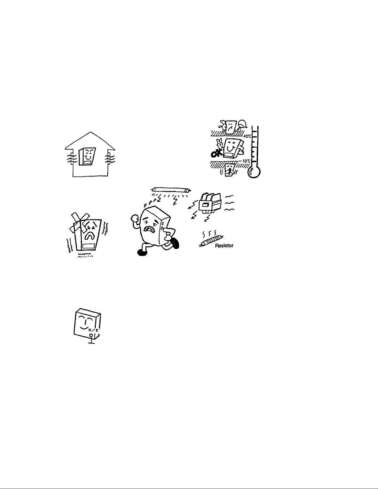
2. installation Precautions
This inverter is an electronic control unit. Take special care concerning the installation environment.
Confirm that the input power is within ±10% of the rated value. If the input power voltage range
tolerances are exceeded during use, the protective circuits may function or the inverter may be
damaged.
Avoid instaliation in hot and humid locations,
where condensation or freezing may occur, or
where water, dust, or metal chips may come into
contact with the inverter.
Install in a location
free of corrosive gases
or cutting fluids, etc.
Do not install the unit
in locations that
experience large
vibrations.
Ground the G/E
terminal to prevent
electrical shock and
Attach the unit to a non-combustible material such as a metal panel. To
ensure adequate ventilation, maintain the following installation spaces, and
always install the unit vertically in the longitudinal direction. When instailing
malfunction due to
noise.
ua/iL
10cm or more
5cm or more
5cm or more
ri
10cm or more
7777777 ‘
Use the unit within an ambient temperature of
-10 to 40°C.
Because the inverter radiates
heat, when installing in a
panel take special care
concerning ventilation and
panel space. Removal of
the cover is recommended
when using in a panel to
ensure maximum longevity
and reliability.
The inverter may malfunction if the
following types of devices are
installed nearby, so use proper
precautions.
• Solenoids ■
• Brakes
• Electromagnetio contactors
- Ruorescent iights
> Resistors
---------
- Install a surge killer
on the exciting coil.
Keep away from the inverter
multiple inverters in a row, leave a clearance of
at least 10cm between each unit. This clearance
can be reduced depending on the environment
or by adding fans.
g
(For 37kW and larger units, leave a clearance of
at least 20cm above and below the inverter to
allow for fan replacement and wire bending
space.)
Contact the Engineering Department for further
details.
Inverter life depends greatly on the ambient temperature. Make sure
that the ambient temperature of the installation location does not exceed the
maximum ambient temperature rating (40°C). ^
Measure the temperature at the positions shown in the diagram on the right,
and confirm that it is less than the maximum ambient temperature rating
(40°C). (50°C or less when the cover is removed.)
22kW and larger units can be used up to an ambient temperature of 50°C.
(Do not remove the cover from 22kW and larger units.)
* Always install the inverter in the longitudinal direction on a vertical surface.
- 2
Sett
Measurement position
Measurement position
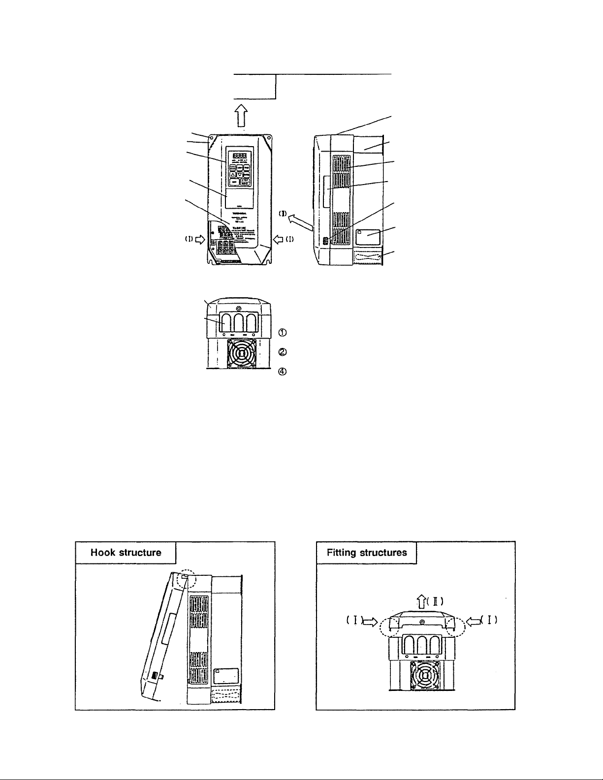
3. External View and Component Names
3.1 Component Explanation (I)
0 Cooling air exhaust port
® Mounting hole (4 holes)
® Mounting bracket
® Operating panel
® ROM interface window
(semi-transparent)
® Front cover warnings
@ Cover (plastic)
©) Wiring access plate: '
Always cut out the wiring
ports as necessary.
When using an 11kWor larger unit,
make slits in the rubber bushing
with nippers or a knife as
shown below.
© Upper caution sticker;
Always remove this sticker when the ambient
temperature is high.
® Ventilation slots:
A cover-up plate option is available for fully-sealed
applications.
_ \
Slit
Rubber
bushing
© Upper caution sticker
® Chassis (plastic)
© Ventilation slots
0 Optical cable access slot
for installation of optical
communication options.
© Finger clasp for
removing cover
O Rating nameplate
© Cooling fan
Operating panel: removable
Refer to section 3.3 Removal of operating panel.
ROM interface window: removable
Refer to section 3.3 Removal of ROM interface window.
Cover
Always read the cautions ® on the front of the cover and remove
the cover when wiring.
Refer to section 3.2 Removal of cover.
H the ambient temperature of the inverter unit exceeds 40°C when
mounted in a panel, remove the cover. The unit can then be used
up to a temperature of 50°C.
3.2 Removal of Cover
1)
For 7.5kW and smaller... Place your fingers on the finger clasps for removing the cover shown In the 3.1 Component Explanation
(I) drawing. Apply force in the direction of the arrows (1), and pull the cover up in the direction of arrow
(n). The cover will come off.
For 11~18kW... Remove the two screws on the cover wiring iniet, and then remove the cover like the 7.5kW models.
For 22kW and larger... Wait for the "CHARGE* lamp on the cover (sheet metal) to go out. Then remove the four screws holding
the cover (six screws for 37kW and larger), and the cover will come off.
- 3 -
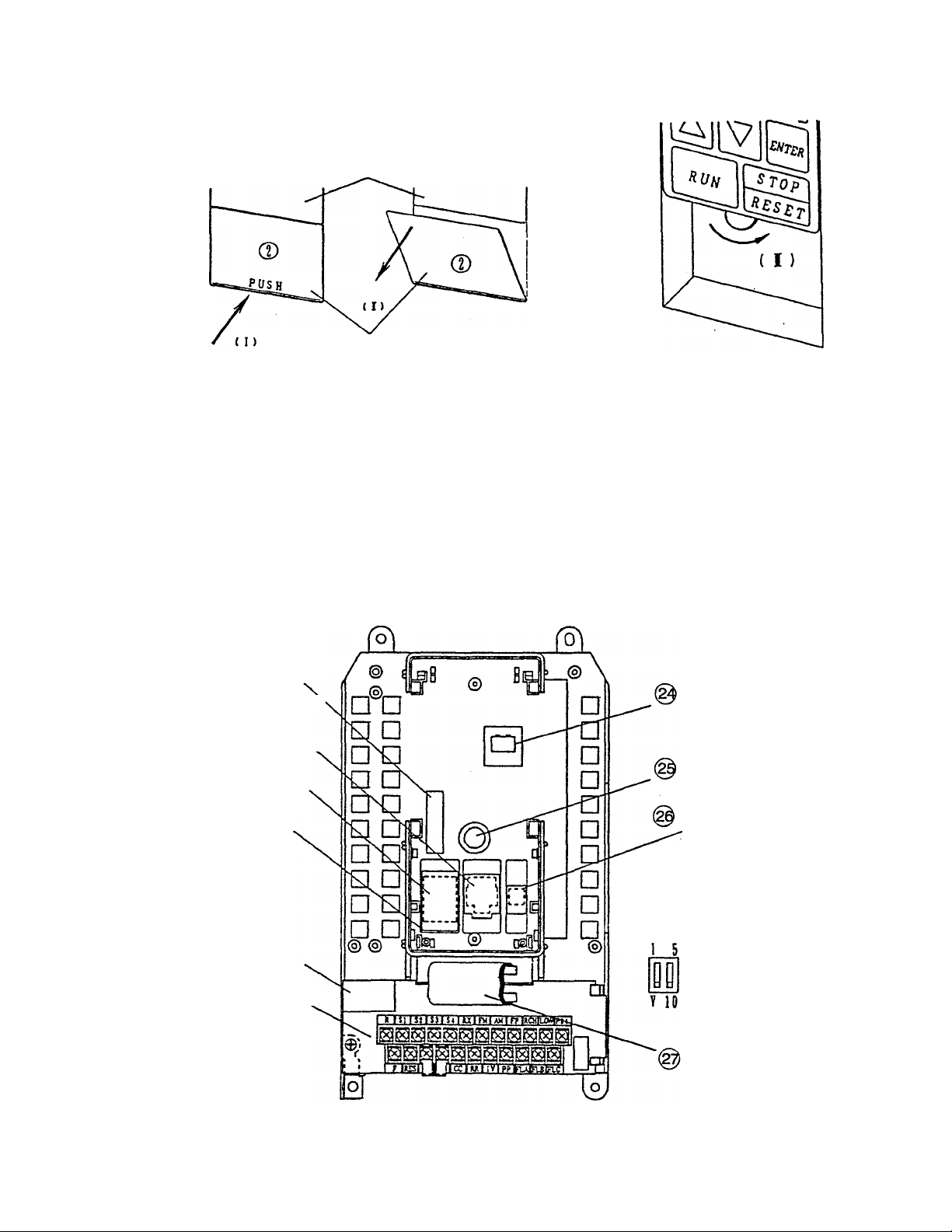
3.3 Removal of the ROM Interface
Window and Operation Panei
Operation panel
ROM interface window
(I) Press where the word PUSH is located.
I
The top of the window will open.
1
(n) Hold the top of the window, and
pull it out in the direction of
the arrow (II).
( iV )
(m) The operation panel attachment
screw can now be seen. Turn it
in the direction of the arrow
(HI) until it completely
loosens.
(TV) When the screw has
completely loosened, pull the
operation panel out in the direction
of the arrow (TV).
3.4 Component Explanation (II)
@ Option connector
(40-pin)
^ RS232C communicatioiY
connector
(Modular 6-pin)
@ Option ROM socket
ROM cover
Option connector
(20-pin)
Control terminal block
Operation panel
connector
Operation panel
attachment stud
Changeover switch for
frequency setting
signal inputs
IV terminal l/V changeover switch
RX terminal 10V/5V changeover switch
- 4 -
Flat cable
(for control terminal block)

4. Operation Precautions
Observe the following points when using the VF-A5 inverter
4.1 Cautions Regarding Motor
Comparison with com
mercial power source
operation:
Running at low-speeds:
Adjustment of overload
protection level:
Running at speeds
exceeding 60Hz:
The VF-A5 inverter uses a sinusoidal-wave PWM method, but the
output voltage and output currertt will be distorted waveforms which
closely approximate sinusoidal waveforms, instead of complete
sinusoidal waveforms. In comparison to operating with the commercial
power source, the motor temperature rise, noise and vibration will
increase slightly.
When the inverter is used in combination with a general purpose
motor and run at low speeds, the motor’s cooling effect will decrease.
Therefore, the output load must be reduced to less than the rated
load. If the motor is to be run at the rated torque even at low speeds,
use a Toshiba 'VF motor* specially designed for use with inverters.
When used with a VF motor, the inverter’s overload protection level
must be adjusted. (Refer to pages 72, 73 for details.)
When using this inverter with a general purpose motor, the overload
protection of the VF-A5 is performed by use of an overioad detection
circuit (electronic thermal relay) that meets a general purpose motor’s
reduced load characteristics. The reference current value for this
electronic thermal relay is set to the inverter’s rated current value;
therefore, this may need adjustment depending on the motor.
When operating at a frequency that exceeds 60Hz, motor vibration
and noise wiil increase. Furthermore, this type of operation may be
limited by the motor’s mechanical strength and bearing construction,
so please contact the motor manufacturer for further information.
Load equipment lubrication
method:
Ultra-light loads and lowinertia loads:
Measures for instability
phenomena:
When driving an oil-lubricated speed reduction gear or geared motor,
the lubrication may deteriorate at low-speeds, so contact the speed
reduction gear manufacturer for information on usable variable-speed
areas.
Instability phenomena, such as abnormal vibration or overcurrent
trips, may occur when operating with an ultra-light load at a load ratio
of 5% or less, or with a load having an extremely small moment of
inertia In these cases, lower the carrier frequency. (Refer to page 66)
Instability phenomena may also occur when using the inverter with the
following types of motors or loads, so always confirm applicability
before use.
(1) Combination with motor exceeding recommended applicable
motor rating.
(2) Combination with special motors such as explosion-proof motors.
(3) Combination with special loads having severe rotational
fluctuations, such as piston-type movements.
- 5 -

Braking during power off:
The inverter will enter the coast-stop state when the power source is
turned off. The motor will therefore not stop immediately. To stop the
motor immediately, install an auxiliary brake unit. Dynamic braking
units and mechanical braking units are available, so select one that
suits your specific appiication.
Loads that generate a
negative torque:
Motors with brakes:
The overvoltage protection or overcurrent protection may function and
trip the inverter when used with loads that generate a negative torque,
in this case, a braking resistor that meets the load condition must be
instalied.
If a motor with a brake is directly connected to the inverter, the
voltage when the motor is started will be low, which may result in the
brake not being released. In this case, separately wire the brake
circuit and motor main circuit. In addition, there is a delay in the time
to when the inverter output stops if the inverter’s ST to CC control
terminal connection is released, so use of the circuit configuration in
Fig. 4-1 is recommended.
In Fig. (a), the brake power is turned ON and OFF via MC2 and MC3.
If a circuit configuration as shown in the drawing is not used, a bound
current may flow during braking and may cause an overcurrent trip.
The brake power can also be turned ON and OFF using the low-
speed signal LOW as shown in Fig. (b).
(Non-excited brake)
Fig.4.1 Circuit configuration for motor with brake
In some cases, such as in hoist applications, turning the brake ON and
OFF by using low-speed detection (LOW terminal function) may be better,
so contact your dealer for further details.
4.2 Cautions Regarding the inverter
Inverter’s overcurrent
protection:
Overcurrent protection is used as the VF-A5 inverter’s protection
function, and the current setting level is set to match the largest
applicable motor. Therefore, when operating a motor that is smaller
than the inverter capacity, the overcurrent level and electronic thermal
protection parameters must be readjusted. (Refer to pages 72, 73.)
Running with light loads:
Operating a large capacity motor with a light load using a small
capacity (kVA) inverter must be avoided. The output peak current will
increase due to the current ripple, and overcurrent trips may
frequently occur.
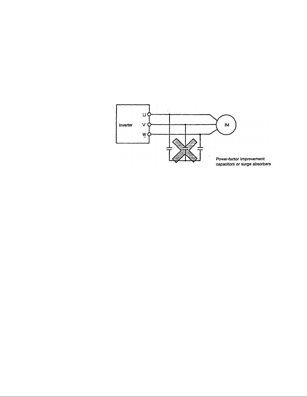
Power-factor improvement
capacitors;
Use with voltage sources
other than the rated voltage:
Protection device for
lightning surges:
Power-factor improvement capacitors must not be installed on the
inverter’s output. When operating a motor with power-factor
improvement capacitors installed, remove the capacitors, or the
inverter may fault trip or the capacitors may be damaged.
Use with voltage sources other than the rated voltage is not possible.
If necessary, use a transformer, etc., to increase or decrease the
source voltage to the rated voltage.
A DSA (lightning surge absorber) is used for protection in the unit. If a
surge voltage exceeding 2600 to 3600V peak is applied, the device
will light like a glowing electrical discharge. This will cause no
problems if the condition does not continue for an extended period of
time.
(Refer to Fig. 6-2-1 Fig. ® on page 21.)
7 -
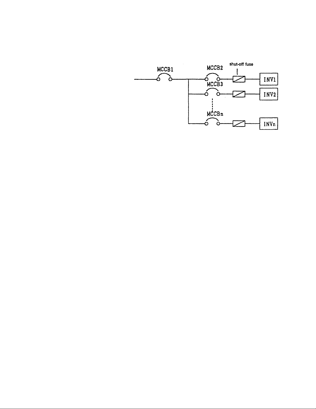
Use of multiple inverter
units:
Observe the following points when using multiple inverter units on the
same power source line.
High-speed
As Shown above, there is no fuse installed in the inverter’s main
circuit, if a short circuit fault occurs in the inverter, not only MCCB2
will trip, but the main breaker MCCB1 may also trip.
Select the shut-off characteristics of MCCB1 and MCCB2 so that a
selective shutdown can be executed and only MCCB2 trips. If the
optimum characteristics cannot be selected, install a high-speed shut
off fuse after MCCB2. (Refer to page 14 for MCCB selection.)
4.3 Inverter Disposal Precautions
Observe the following points when disposing of the inverter.
Explosions from
incineration:
Gasses from plastics:
Disposal method:
Placing the inverter in an incinerator may be dangerous, as the
electrolytic fluid used in the electrolytic capacitors may expand and
explode.
The plastic used for the cover, etc., may generate poisonous gases
when incinerated.
Commission the disposal of the inverter to a specialist.
- ft -

5. Wiring Precautions
5.1 Connection to Main Circuit (Refer to page 11, Fig. 5.1.)
Observe the following precautions when making connections to the inverter.
Confirmation of power OFF:
Electrical shock preventionconfirmation of charge
dissipation:
Confirmation of main circuit
connections:
Separation of power source
and motor wiring:
Separation of control and
main power supplies:
Always turn the primary power distribution panel switch OFF, and
confirm with a tester that a voltage is not present before beginning
wiring to the inverter.
Before changing the wiring, wait at least five minutes after the
•CHARGE“ lamp inside the inverter has gone out, and then confirm
that the capacitors have fully discharged by using a tester, etc., that
can measure high-voltage DC. The internal electrolytic capacitors are
charged, and there is a danger of electrical shock If the charged
areas are touched while the "CHARGE' lamp is on. Do not touch the
terminal block or remove the upper cover while the lamp is lit
The inverter will be damaged If the input power source is applied to
the motor terminals (U/T1, V/T2, W/T3). Always confirm the wiring for
the power source terminals (R/L1, S/L2, T/L3) and motor terminals
(U/T1, V/T2, W/T3) before turning the power on.
To prevent problems due to radio-frequency noise, etc., do not bundle
the wiring to the input power terminals (R/L1, S/L2, T/L3) and the
motor terminals (U/T1, V/T2, VJfTS) together.
In order to maintain the control power supply to display faults or to
operate the communication options while the main circuit power is
shut down, remove the two shorting bars (between R/L1-R0, S/L2-S0)
on the control power supply terminal block. Connect the control
power to a power source that is separate from the main circuit supply.
5.2 Connection of Control Signals
Observe the following points when making control signal connections.
Rating of relay contacts:
Power wiring for control
circuit:
Control wiring wire sizes:
Isolation from main circuit:
Use a relay intended for use with micro-current (min. applicable load
rating less than 4mA-24V.), and install a surge killer on the relay’s
exciting coil.
Use shielded wiring or twisted-pair wiring for the control circuit, and
separate the wiring from the main circuit wiring.
The following wiring sizes for the control circuit are recommended.
Frequency setting signal input, frequency meter, ammeter: shielded
wire that is 0.3mm® or larger
Other signals: Vinyl-insulated wire that is 0.75mm® or larger
All control terminals other than FLA, FLB and FLC are connected to
Internal electronic circuits, so input signals must always be electrically
isolated from the main circuit.
9-

Ratings of connected
meters:
Connect a full-scale 1 mAdc DC ammeter or full-scale 7.5Vdc-1 mA DC
voltmeter to the control terminals.
Rating of FL signal contacts:
External use of control
power:
Open collector outputs:
Frequency-setting
potentiometer:
5.3 Other Precautions
Use of crimp-on terminal
lugs:
The contact rating of the protection operation detection relay (FL) is
250Vac (cos0=O.4) 30Vdc-1A.
A max. of 24Vdc-100mA can be used from the P24 control power
terminal to drive external relays.
The RCH and LOW control terminals are open-collector outputs, and
can output a max. 24Vdc-50mA. Use of a 24Vdc OMRON MY1 relay
(RY) is recommended.
Always install a diode (200V-1A class)
for surge absorption. Take special note
of the diode polarity to avoid incorrect
application.
Use a potentiometer rated at 1k to 10kO-1/4W for the frequency
setting Input signal.
The clearance between terminals on the inverter main circuit terminal
block is small, so use sleeved crimp-on terminal lugs for all main
circuit terminals. Take special care during connection so that the
terminal lugs do not make contact with neighboring terminal lugs.
P2<
RCH
Grounding terminal:
Built-in braking resistor
Internally-connected (E)
terminal:
The main circuit wiring is shown in Fig. 5.1.
(For 3.7kW or less, not showing control power terminals RO, SO)
Always ground the G/E grounding terminal with a wire that is 3.5mm®
or larger.
For inverter capacities that are 3.7kW or less, a built-in braking
resistor is connected between the main circuit terminals (PA1) and
(PB1), providing dynamic braking as a standard feature.
The (E) terminal is for internal connections, so do not remove
connections from it or make any external connections to it.
-10 -
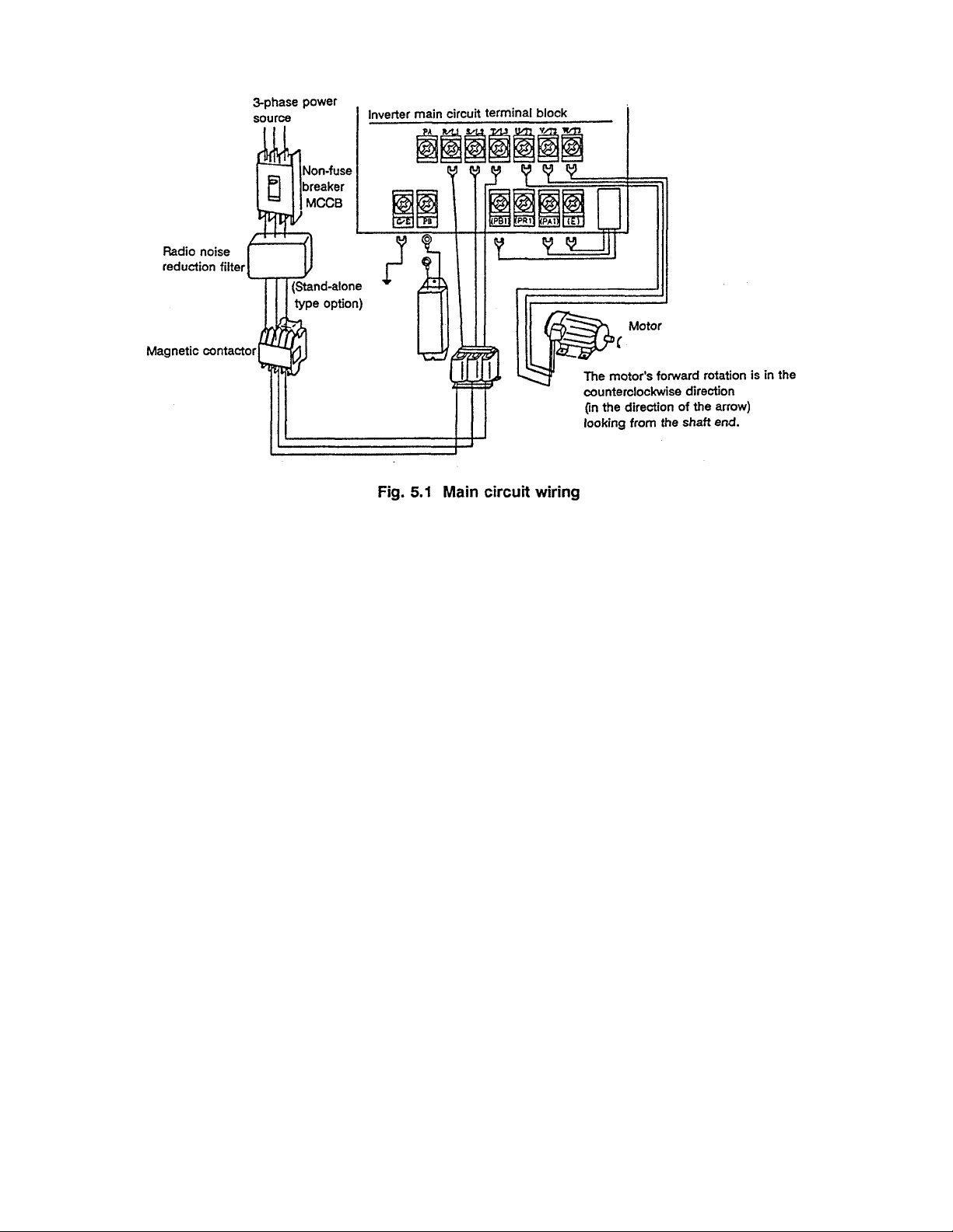
Note) A DC reactor (stand-alone type option) can be installed on 5.5kW and larger units. (Refer to the
function of main circuit terminals PO and PA on page 18.)
Installation of non-fuse breaker
(1) Install a non-fuse breaker (MCCB) for wiring protection on the input power source side.
(2) Avoid frequent starting/stopping by turning the non-fuse breaker ON and OFF.
(3) Start and stop by turning terminals F to CC (or R to CC) ON and OFF.
Installation of primary magnetic contactor
(Refer to page 14; Examples of selecting equipment for wiring.)
(1) When using an external braking resistor, install a magnetic contactor (MC) or non-fuse breaker with
trip coil (MCCB) on the inverter's power supply input side for protection. Make sure that the power
circuit can be opened with the built-in fault detection relay (FL).
(2) The VF-A5 has a built-in fault detection relay (FL). Connect the contacts of this relay to the primary side
magnetic contactor (MC) operation terminals, so that the MC can be opened when the inverter’s
protection circuit functions.
The fault detection relay (FL) contacts (250VAC-1A cos0=O.4) can be directly connected on 200V
systems. When using a 400V system, a transformer must be used to create 200V or less for the FL
sequence.
If the MC exciting current exceeds the FL contact rating, install another relay step.
(3) Turn terminal F (or R) to CC ON and OFF to frequently start and stop. Due to repeated inrush currents
when the power is turned on, the life of the inverter will be shortened when the primary magnetic
contactor is used to start and stop, so do not use this method to start and stop frequently.
(4) Install a surge killer on the magnetic contactor (MC) exciting coil.
-11
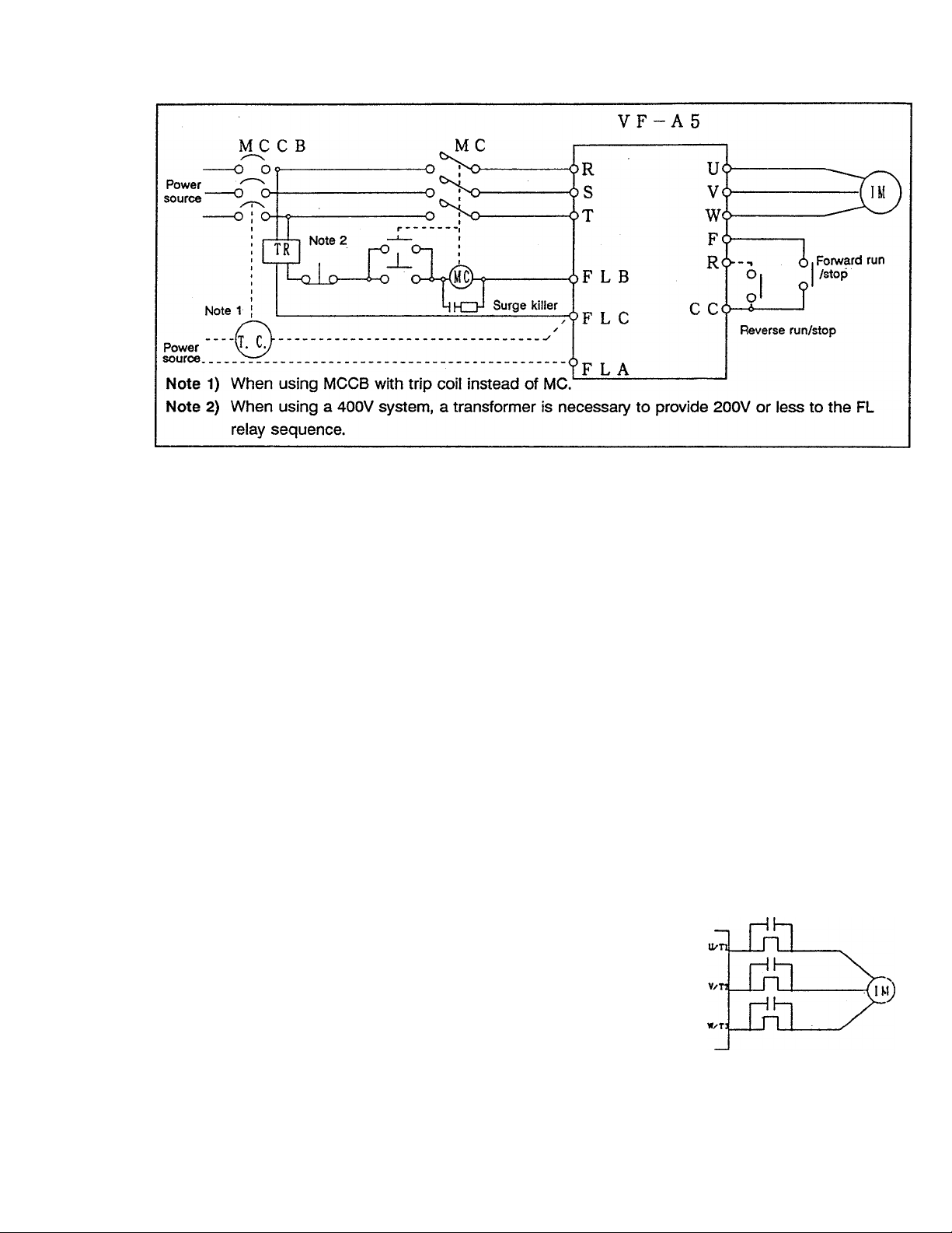
Fig. 5.2 Wiring example using a magnetic contactor
installation restrictions of secondary-side magnetic contactors
(1) As a rule, if a magnetic contactor is installed between the inverter and motor, do not turn it ON/OFF
while running. (If the secondary-side contactor is turned ON and OFF while running, a large current
may flow in the inverter, causing inverter damage and failure.)
(2) A magnetic contactor may be installed to change the motor or to change to the commercial power
source when the inverter is stopped. Always use an interlock with the magnetic contactor in this
situation so that the commercial power supply is not applied to the inverter’s output terminals.
Installation of overload relay (thermal relay)
(Refer to page 14; Examples of selecting equipment for wiring.)
(1) The VF-A5 has a built-in overload protection function that uses an electronic thermal relay. However,
in the following cases, the thermal relay operation level must be adjusted or an overload relay matching
the motor’s characteristics must be installed between the inverter and motor.
0When using a motor having a rated current value different from a Toshiba general-purpose motor.
(Adjust the electronic thermal level)
©When running a single motor with an output less than the specified standard applicable motor, or
when running several motor simultaneously (An overload relay must be installed on each motor.)
Note) If the motor cables for a 400V class inverter are long, the thermal
relay may malfunction. In this case, lower the carrier frequency (refer
to adjustment parameters on page 66), or install a 0.1/r to O.SpF-
1000V film capacitor between the input/output terminals of each
phase’s thermal relay.
< Example > When using external thermal relays, the inverter can be externally fault-tripped and
immediately stopped by using the following method (Fig. 5.3).
12

Note) In this case, ensure that S4 is set to 'Emergency
stop function", by setting | /h H [in
0 r. 5 h to ID.
If the Th-Ry functions, the inverter will display
• E ', and fault trip.
* Other unused terminals can also be used instead of the S4
terminal.
Fig. 5.3 Wiring example using external thermal relays
C r. 51 etc., indicate the LED display on the operation panel. (Refer to Appendix 3, Character
codes, on page 123. The boxed items indicate a parameter or panel operation key.
When using the VF-A5 to drive a Toshiba VF motor*, designed exclusively for constant torque/inverter-
(2)
driven applications, set the electronic thermal protection characteristics for a VF motor.
(Refer to pages 72, 73, Electronic Thermal Protection.)
For protection measures, use of a motor with an imbedded-type thermal relay in the motor coil is
(3)
recommended when running a motor at low speeds.
Restrictions on the installation of power-factor improvement capacitors (both input/output)
Do not install power-factor improvement capacitors on the input or output sides of the inverter. Large
currents containing high frequency elements may flow to the capacitors and adversely affect them.
Capacitors on the output side may cause the inverter to overcurrent trip. Install an input reactor or De
link reactor (optional) for power-factor improvement.
Countermeasures against radio wave interference
The inverter may cause radio wave interference to audio equipment, etc., used near the inverter. In this
case, install a radio noise reduction filter (optional) on the inverter’s power source side, or shield the
cables to the motor with a conduit to reduce the interference. Contact your dealer for further details.
Cautions concerning ground faults
Verify that there are no incorrect connections between the motor and inverter and that there are no
short circuits in the motor before beginning operation. Do not ground the neutral point of a starconnected motor.
Installation of an input reactor
An input reactor can be used to improve the input power-factor, to suppress high harmonic elements,
and to miminize the risk of damage to the inverter that may be caused by sudden power fluctuations.
Always install an input reactor when connecting the inverter to the following types of systems.
(1) When power source capacity is SOOkVA or more, and when power source capacity is greater than
the inverter capacity by a factor of 10 times or more.
When connecting the inverter to the same power system as thyristor-commutated control
(2)
equipment.
When connecting the inverter to the same power system as a distorted-wave generation source,
(3)
such as an arc furnace or thyristor-switched converter unit.
Leakage currents
Leakage currents may increase slightly depending on the connection method.
(1) When multiple inverters are connected to one ELCB, increase the ELCB current sensitivity value.
(2) Keep the wiring length between the inverter and motor as short as possible.
(3) Use an ELCB with high-harmonic suppression.
-13

Voltage
dass
200V
class
400V
class
Appncabfe
motor
m
0.4
0.75
1.5
2.2
3.7
5.5 -2055P
7.5 -2075P
11
15 -2150P
18.5 -2185P
22 -2220P
30 -2300P 200
37
45 -2450P
55 -2550P
75 -2750P
0.75
1.5 -4015P 10
2.2
3.7
5.5
7.5 -4075P
11
15 -4150P 60
18.5
22
30
37
45 -4450P 150
55
75
Inverter
Model
-2004P
-2007P 10
-2015P 15
-2022P
-2037P 30
-211 OP
-2370P
-4007P
-4022P 10
-4037P 15
-4055P
-4110P
-4185P 75
-4220P
-4300P
-4370P
-4550P
-4750P 225
Table 5.1: Examples of selecting equipment for wiring
Non-fuse breaker
(MCC8)
Rated
current
Toshiba
(A)
model
SS30
5
SS30
SS30
20 SS30
SS30 18
ESSO
50
EH100
60
EH100
100
125 EH225
EH225
125
EH225 93
150
EH225
EH225 180
225
EH400
250
EH400 220
250
500 SH600
SS30
5
SS30 9
SS30
SS30 9
SS30
30
30 SS30
ESSO 33 C35A
50
EH100 48
EH100 50
100 EH100
EH225 80 C80A
125
EH225 93
125
EH225 180 C180A 85
175 EH225
EH225
Magnetic
contactor (MC)
Toshiba
Rated
current
model
(Note 1)
(A)
C12A 2.3
12
12 C12A
12 C12A
12 C12A 9.3
C20A 15
35 C35A
50 C50A 28
65 C65A 43
C80A
80
93 C100A 70
C100A 85
180 C180A 108
C180A
220 C220A 162
C220A
300 C300A
9 C12A 2.3
C12A 3.6
9 C12A 5.0
C12A
17
C20A
17
C25A 15
C50A 28
C50A 35
50 C50A 43
C100A
180 C180A 108
220 C220A
Overload relay
Th-Ry
cunvnt value
_ w
{Reference
vfeue]
4.2
6.6
22
57
138
198
3.6
8
11
22
57
70
138
Toshiba
model
T11A
T11A
T11A
Til A
T20A
T35A
T35A
T65A
T65A
T80A
T125A
T125A
T150A
T180A
T220A
T400A
Til A
T11A
Til A
T11A
T20A
T20A
T35A
T35A
T35A
T65A
T65A
T80A
T125A
T125A
T150A
Surge killer
Model
(Note^
Toshiba
model SS-2
Marcon
Bectronics
RFM2E224KD
Model SS-2
Marcon
Bectronics
RFM2H104KD
(400V system)
(Note 6)
Wire size
Main
ciicuit
(mm^
(Notes)
Control
dfcuit
(mm^
(Note 4)
Dynamic
braking
(mm®)
2.0
2.0
2.0
2.0
3.5
0.75 or
larger
5.5
8.0
or
14
14
22
38
38
60
22
100
100
60
100
100x2
2.0
22
38
38
38
60
100
14
2.0
2.0
2.0
3.5
5.5
0.75 or
larger
2.0
3.5
8.0
22
or
(Note 1) When selecting a magnetic contactor (MC) with 2a auxiliary contacts and using the auxiliary contacts for the control circuit,
parallel the 2a contacts to improve contact reliability.
(Note 2) Install a surge killer on the magnetic contactor or relay exciting coil.
(Note 3) The wire sizes for the input side R, S, T and output side U, V, W are shown. These sizes apply only when the wiring length is
(Note 4) Use shielded wire.
(Note ^ Use a wire size 3.5mm® or more for the grounding wire.
(Note 6) 200V system: type SS-2 or Marcon Bectronics RFM2E224KD
less than 30m. Increase the wire sizes when the length exceeds 30m.
- 14 -
6. standard Connections
Refer to the operation selection expianation (7.4 Operation mode seiection, page 40), and parameter list
(page 105).
6.1 Standard Connection Example
Example 1 To set run frequency, forward/reverse run, and decelerated stop via the panel.
3-phase main circuit
power source
Operating frequency setting
In standard configuration, F)0 and SO
are connected with jumpers to the main
circuit terminals. (Only for 30kW and smaller)
(Refer to page 18.)
Setting
Parameter group Parameter
Gi-.Ut
C r-.U k
C no d (Command mode selection)
F nOd (Frequency setting mode
selection)
via the panel
These are jumpered at shipment.
Setting value
Reference page
Bci H №••
2orH Notes)
40
40
Note 1)
rrwod:
rrwj'B:
set to B ... Press RUN to start running,
set to H ... Press PANEUREMOTE , then
RUN
to start running.
* Refer to page 28 '7.2 Basic Operation* for the operation methods.
Note 2) I F n n rl I set to B ... The reference frequency can be set only from the operation panel.
Setting
Parameter group
Or-.ut
0 r.U k
C nod (Command mode selection)
F nod (Frequency setting mode
Parameter
Setting value Reference page
1 OT H Not»3)
B
selection)
40
40
twice.Note 3) Emergency stop is possible from the panel by pressing STOP
I r n n H 1 set to / ... Running from operation panel is not possible.
I r n n r/1 set to M ... Press rPANELVREMOTE , and running is possible from the
operation panel by pressing RUN
15 -
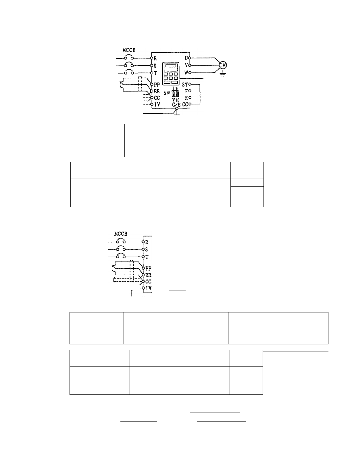
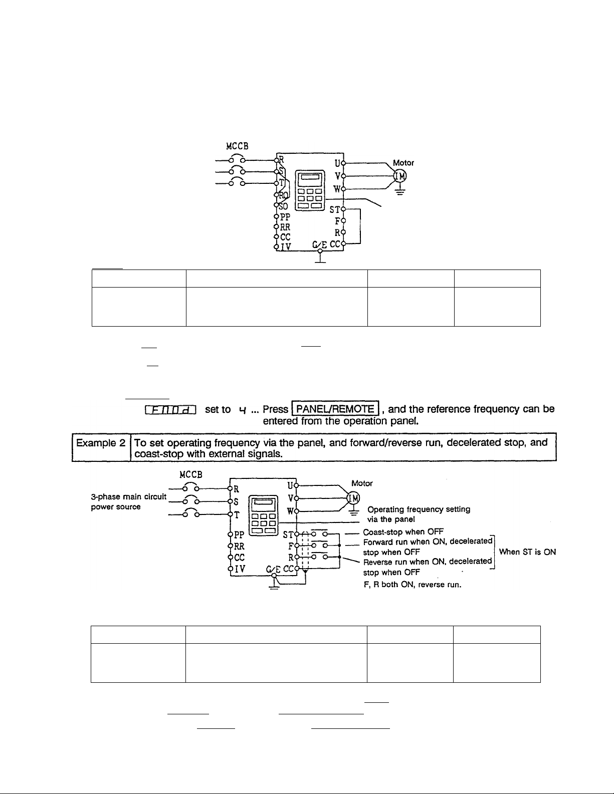
Example 3
To set operating frequency with external signals, and forward/reverse run and
decelerated stop with the panel.
__________
________
3-phase
main circuit
power source
0 Potentio
meter
@0~10Vdc
® 4~20mAdc Crirriy
0~10Vdc
Setting
Parameter group
Gr.Ub
Cr.Ut Fnod (Frequency setting mode
External operating
frequency signal
® Potentiometer
0 0~10Vdc
® 4~20mAdc
0~10Vdc
Example 4
Motor
Operating via the panel
or T
The switches are under the ROM
interface window. (Refer to page 4.)
Parameter
E no d (Command mode selection)
Setting value
1
Reference page
40
40
selection)
Cr.5F F[ 1 Setting value
Switch
SW
1
!
d
E
V side
1 side
V side
Note 5) Refer to page 69.
To set operating frequency, forward/reverse run, decelerated stop, and coast-stop via
external signals.
3-phase
main circuit
power source
0 Potentio
meter
@0~10Vdc
0 4~20mAdcCrrrrryir
I s
sw|m
VIO
G/ECC<^
Setting
Parameter group
Gr-.Uk
Er.Ub
E no d (Command mode selection)
F n Dd (Frequency setting mode
Parameter
selection)
External operating
frequency signal
Cr.5F FCI Setting value
0 Potentiometer
© 0~10Vdc
© 4~20mAdc E
0~10Vdc
STy-fA-o
FQ-i-fö”
R64-4-0
/
1
E
Motor
Coast-stop when OFF
Forward run when ON, decelerated-
stop when OFF
Reverse run when ON, decelerated
stop when OFF
F, R both ON, reverse run
Setting value
/ 0 r 4 Note 3)
/ 0 r 4 Note 4)
Switch
V side
1 side
V side
Note 5) Refer to page 69.
When
ST is ON
Reference page
40
40
Note 4) Emergency stop is possible from the panel by pressing STOP | twice.
I F n D dl set to / ... The reference frequency can only be input from the terminal block.
1 F n Dd 1 set to 4 - Press | PANELVREMOTE |, and the reference frequency can be
entered from the operation panel.
16
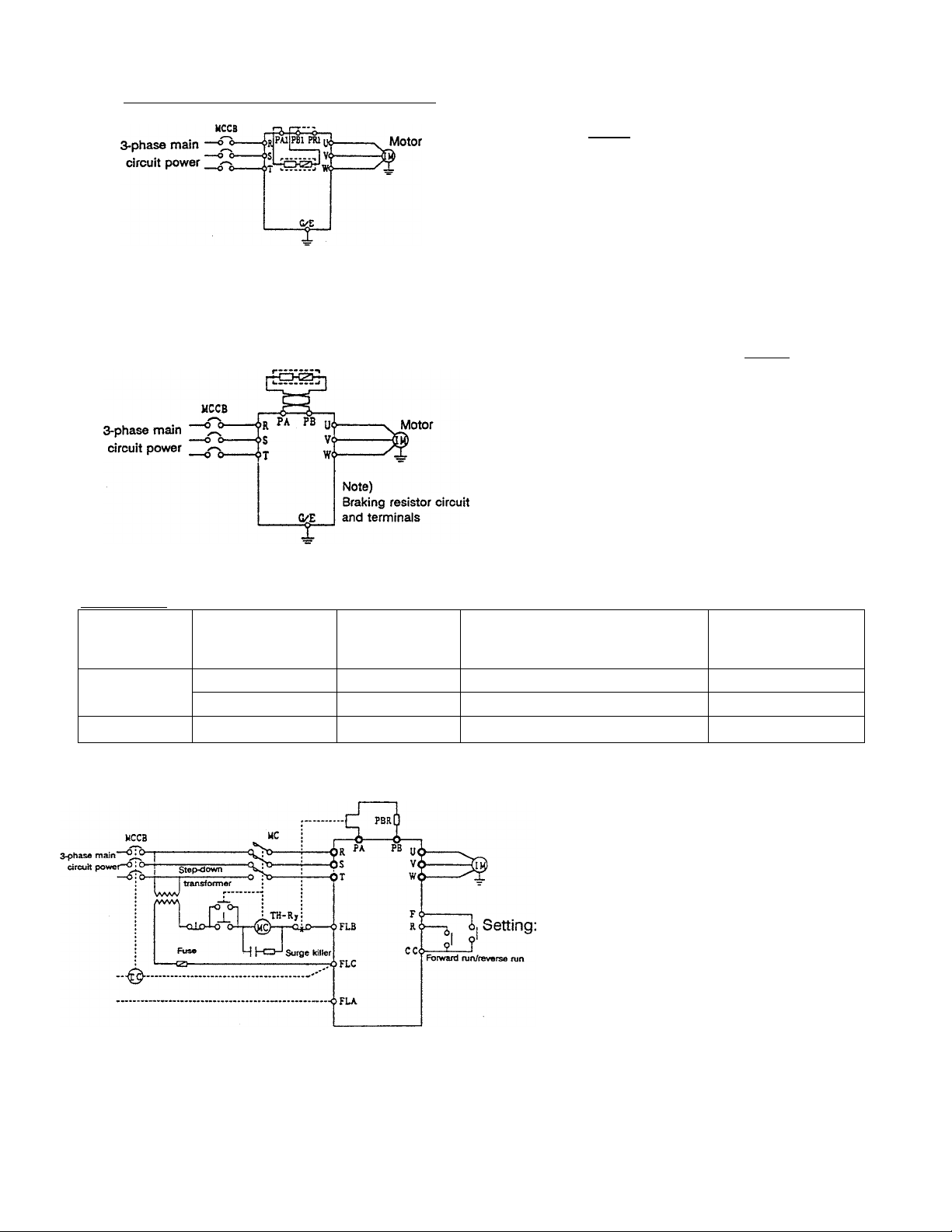
Example 5 When using built-in braking resistor
(Note) Move PR1 wiring to PB1
Example 6 When connecting a braking resistor (optional)
Note) Select a braking resistor that is higher than the min. tolerable resistance value (refer to page 95). For
22kW and larger units, the separate GTR7 (dynamic braking circuit) option is required,
a) When using an optional braking resistor with temperature fuse
Braking resistor
Setting: Set I Pbi in parameter group Cr.Pr
Setting: for 5.5kW and larger units, set I P b I in
(For 3.7kW and smaller units)
(dynamic braking selection) to 5 (dynamic
braking with overload detection).
The built-in braking resistor is connected to the
PB1 terminal (refer to page 23) at shipment.
parameter group ür.P r (dynamic braking
selection) to S (dynamic braking with overload
detection).
When using the built-in braking resistor with 3.7kW and smaller units, avoid the use of an external braking
resistor. However, parallel connection is possible in the following combinations. (For max. braking rate
applications)
Buift-in braking
resistor
200V systems 2.2kW and smaller
3.7kW
400V systems
When using an optional braking resistor without temperature fuse
b)
3.7kW and smaller 150n
70n
40n
Minimum external resistor
value that can be used with the
built-in braking resistor
70n 3sn
40n 20n
150n
TH-Ry is used as a fire prevention fail-safe.
DBR overload and overcurrent protection
functions are incorporated in the inverter
for protection of the braking resistor, but
TH-Ry operates if those protective
functions are not possible. Select TH-Ry
according to the DBR power rating.
(dynamic braking selection) to 2 (dynamic
braking with overload detection), and set the
braking resistor capacity and resistance value.
(Refer to I Pbc I | PbCP I on page 77.)
Min. total braking
resistance value
75Í1
Note) The step-down transformer does not need to be installed for 200V class inverters.
-17 -

6.2 Terminal Functions
Table 6.2.1: Main circuit terminal functions for 3.7kW and smaller units
Main circuit terminal functions for 3.7kW and smaller units are as shown below. The internal circuit
Terminal symbol
G/E
R/L1, S/L2, T/L3
U/T1, V/T2, W/T3
PA, PB
Terminal for external grounding.
Connect to properly-rated power source.
Connect to motor (3-phase induction motor).
When built-in braking resistor is insufficient, connect to external braking
resistor (optional).
Change the settings related to dynamic braking resistor protection.
PC
Minus potential terminal for internal DC circuit
A DC power source can be input between this terminal and the PA
terminal (plus potential).
RO, SO
Control circuit power is input via the shorting bars on the terminal block
(RA-1-R0, S/L2-S0). When using a separate power supply for the control
power, remove the shorting bars before connecting the power supply.
(PR1), (PB1)
Connected to the built-in braking resistor. When not using the built-in
braking resistor, change the wiring from (PB1) to (PR1)i and then
change the settings of the dynamic braking resistor operation
parameters.
(PAD This is an internal connection, so do not remove wires from it or
connect external wires to it. It is connected to the built-in braking
resistor.
(E)
This is for internal connections, so do not remove or connect external
wires. This is wired to the inverter chassis.
Terminal function
Internal
circuit
diagram
A
A
B
Cl
Cl
D1
C1
Cl
A
Table 6.2.2: Main circuit terminal functions for 5.5kW and larger units
Main circuit terminal functions for 5.5kW and larger units are as shown below. The internal circuit
diagrams for each terminal are shown on page 21.
Terminal symbol Terminal function
diagram
G/E Terminal for external grounding.
R/L1, S/L2, T/L3 Connect to properly-rated power source.
U/T1, V/T2, W/T3
PA, PB
Connector to motor (3-phase induction motor).
Connect to the braking resistor (optional) and then set the dynamic
C2,C3,C4
braking resistor operation parameters.
PC
Minus potential terminal for internal DC main circuit.
C2,C3,C4
A DC power source can be input between this terminal and the PA
terminal (plus potentiaO.
PC, PA
Terminals for connecting a DC-link reactor (DCL) (standalone type).
C2,C3,C4
This is short circuited with a shorting bar at shipment.
RO, SO
Control circuit power is input via the shorting bars on the main circuit
terminal block (R0-R/L1, S0-S/L2). When using a separate power supply
for control power, remove the shorting bars before connecting the
power supply.
On 37kW and larger units, these terminals are not connected to the
main circuit terminals at shipment, so connect a power supply for the
control circuit.
R20, S20
Power supply output terminals (190 to 220V - 50Hz, 190 to 230V 60Hz) for operation circuits. Only installed on 400V-class 37kW and
larger units (10VA).
Internal
circuit
A
A
B
D1, D2
D2
-18-

Table 6.2.3. Control circuit terminal functions
Control circuit terminal functions are as shown below. The internal circuit diagrams for each terminal
are shown on page 22.
Internal
Terminal symbol
Terminal function
diagram
FLA, FLB, FLC
These are the multifunction programmable relay contact outputs (refer
to page 12). The contact ratings are 250Vac-2A (COS0=1), 30Vdc-1A,
250Vac-1A (COS0=O.4).
The standard function setting detects when the inverter protection
functions have operated.
When a protection function activates, FLA-FLC will close, and FLB-FLC
will open.
P24
RCH
24Vdc power output. (Max. 100mA)
This is a multifunction programmable open-collector output (refer to
page 57). (Max. SOmAdc)
The standard function setting activates this signal when completion of
deceleration or acceleration is detected.
circuit
E
F
G
LOW This is a multifunction programmable open collector output (refer to
page 57). (Max. 50mAdc)
The standard function setting activates this signal when a low speed is
detected.
FP
This is a dedicated open-collector output. (Max. 50mAdc). Pulses that
are 48-, 96- or 360-times the output frequency are output according to
parameter settings.
The standard setting is for 48-times the output frequency.
FM This is a multifunction programmable analog output (refer to page 89.)
The standard setting is the pre-compensation reference frequency.
When connecting a meter, use a ImAdc full-scale ammeter or 7.5Vdc-
1mA full-scale voltmeter.
AM This is a multifunction programmable analog output (refer to page 89.)
The standard setting is the output current. When connecting a meter,
use a ImAdc full-scale ammeter or 7.5Vdc-1mA full-scale voltmeter.
PP This is the power supply for reference frequency setting. (lOVdc)
Connect a 3kft potentiometer (a 1 to lOkQ potentiometer may also be
used).
RR This is a multifunction programmable analog input.
The standard setting is a 0 to lOVdc input corresponding to a 0 to
80Hz frequency setting.
IV
This is a multifunction programmable analog input. Change between 0
to lOVdc (SW at V side) or 4 (0) to 20mAdc (SW at 1 side) via SW,
located under the ROM interface window. The standard setting is a 0 to
lOVdc input conresponding to a 0 to 80Hz frequency setting with the
switch at the V side.
G
H
1
1
J
K
L
RX
Tills is a multifunction programmable +!- analog input. Change
between 0 and ±lOVdc (SW at 10V side) or 0 to ±5Vdc (SW at 5V
side) via SW, located under the ROM interface window. The standard
setting is a 0 to ±10Vdc input corresponding to a 0 to 80Hz
forward/reverse frequency setting with the switch at the 10V side.
CC This is the control circuit common terminal. N
-19-
M

Terminal symbol
ST
Terminal function
The standard setting is ‘run ready' with a short circuit between STCC. The motor will coast-stop when opened. This can also be
used for interlocks. (Run ready/ coast-stop terminal)
Internal
circuit
diagram
0
F The standard setting is forward run with a short circuit between F-
R
SI
S2
S3
S4
RES
■ 3
Q.
CC, and decelerated stop when opened. (ST-CC in ON condition)
C
*—•
0
The standard setting is reverse run with a short circuit between R-
ro
CC, and decelerated stop when opened. (ST-CC in ON condition)
c
0
The motor will reverse run when both F-CC and R-CC are short
0
CD
circuited.
JD
CO
The standard setting is preset speed run with a short circuit
e
E
between S1-CC.
CO
O)
The standard setting is preset speed run with a short circuit
0
between S2-CC.
Q.
c
0
The standard setting is preset speed run with a short circuit
0
between S3-CC.
c
3
The standard setting is preset speed run with a short circuit
D
between S4-CC.
The standard setting is that the hold during operation of the
inverter protection functions is reset with a short circuit between
RES-CC.
Even if RES-CC Is short circuited while the inverter is operating
normally, the reset function will not activate.
0
0
0
0
0
0
0
-20-
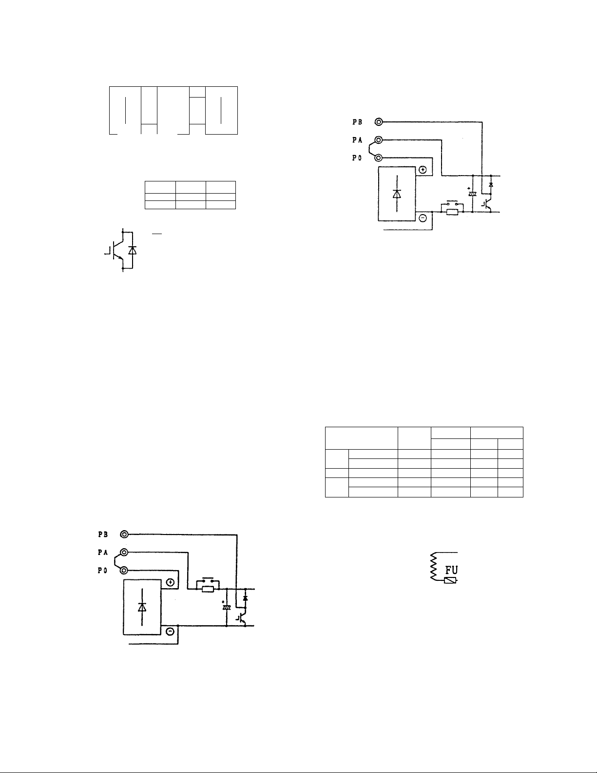
Fig. 6.2.1 Input/output internal circuits (1/2)
Sym
bol
Internal circuit diagram
E/UM
S/lit
T/l><
c/e 0“
Varistor
r
4
MOV
Lightning
L surge
Ad. A absorber
O-
SOOV «yearn •470V aooov
400V tyeam
-tV\ ■
Current detection
circuit
Bultt-in braking r-'*———•
resistor
3.7)Wand smaller
(Ptn
lO-
tfAl)
(Pin ■
"O-
HZ3
PA e-
PB O-
Capacitor
1
T
WrtearMOV
woâageiaang
■AV
‘^fuse
©
2 \
DSAnead
1000V 9000V
tA—@ W/T3
Temperature
U/Tl
V/T2
Sym
bol
Internal circuit diagram
11~18.5kW
PC (§>
22kW and larger
PB (§>—
PA J®
PO t®
PC ®-
„ RlOO
RO®
----
S 0®
-----
-------
--------
<=h-
©
-cm
0
C Bectrolytic capacitor
5.5, 7.5kW
PC ©■
tz
©
InvrtBf cepedty
‘Z/XN
7-5kWand smaller
system
aOkW and smaller
20GV 37kW and larger 60VA lOA-ISmS 33n 200|lF
7JSkWand emaJler
4CeN
system
dOtW and smaller QOVA
400V systam 37-75kW
Max. poDver
Peakinruah Component vatuea
capady
50VA
max. input
50VA
aOA-SmS
SCf^A 20A-7mS lea 220pF
2QA-3mS 320 50|iF
a0A-7mS 32Û IIOpF
RICO
16a lOOpF
c
^ 460:230 150VA
RO©
------=----
S0(§h
R20(§)-
S20©-
-21 -
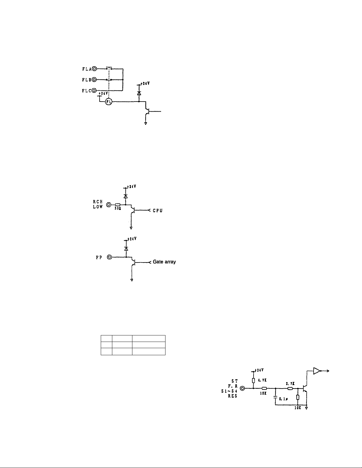
Fig. 6.2.1 Input/output internal circuits (2/2)
Sym
bol
e
©
©
Internal circuit diagram
_a»v
_ t. la T
P2 < ®
----------<z------Fuse resistor
*
< CPU
Sym
bol
©
о
internal circuit diagram
Analog input
(0~10Vdo)
18k
RR ©-
Note 1) Ф
-o-
0. 1a
CC ®------
Analog input
O-'IOVdc, 0~20mAdc)
18k
IY©b
Note 1)
-cu-
hoos
CC ©
------
Cb-IOVdo (switch at V side)
4~20mAdc (swKch at I side)
-F/-Analog input +5V
(o~+/-iovac. (K+/-5Yac)
RX <§>—
Note 1)
CC @—
------
0~6Vdc (switch at 5 side)
0—10Vdc (switch at 10 side)
Voltage converter clrcuft^ ^
Ik 33k 33k
CD- -Oj-CD—
0. iM
+ 5V
2^
A/D converter
SVmax
ll5k 2Í
+ 5V
2^
A/D converter
SVmax
5k 2i
A/D converter
2.5V±2.5V
Analog output
(D
Ф
cc ©—
4.7k
0. u
AM
PM lOOmS
PP ®-
= T
Response
3mS
Low-pass
filter
circuit
1/1024 or better
OOQ
5. lVx2
-< CPU
Resolution
1/256
©
Contact inputs
CC
@-
C/l@-
j.
Grounding
capacitor
22piF
CPU
■jü. lA
CC ©
------
1
Note 1) A capacitor is installed on the analog input terminals (RR, RX, IV), so if an output such as an
operational amplifier is directly connected to these terminals, instability may result. Always pass signals
of this type to these terminals through a lOOft to Ikfi resistor.
-22
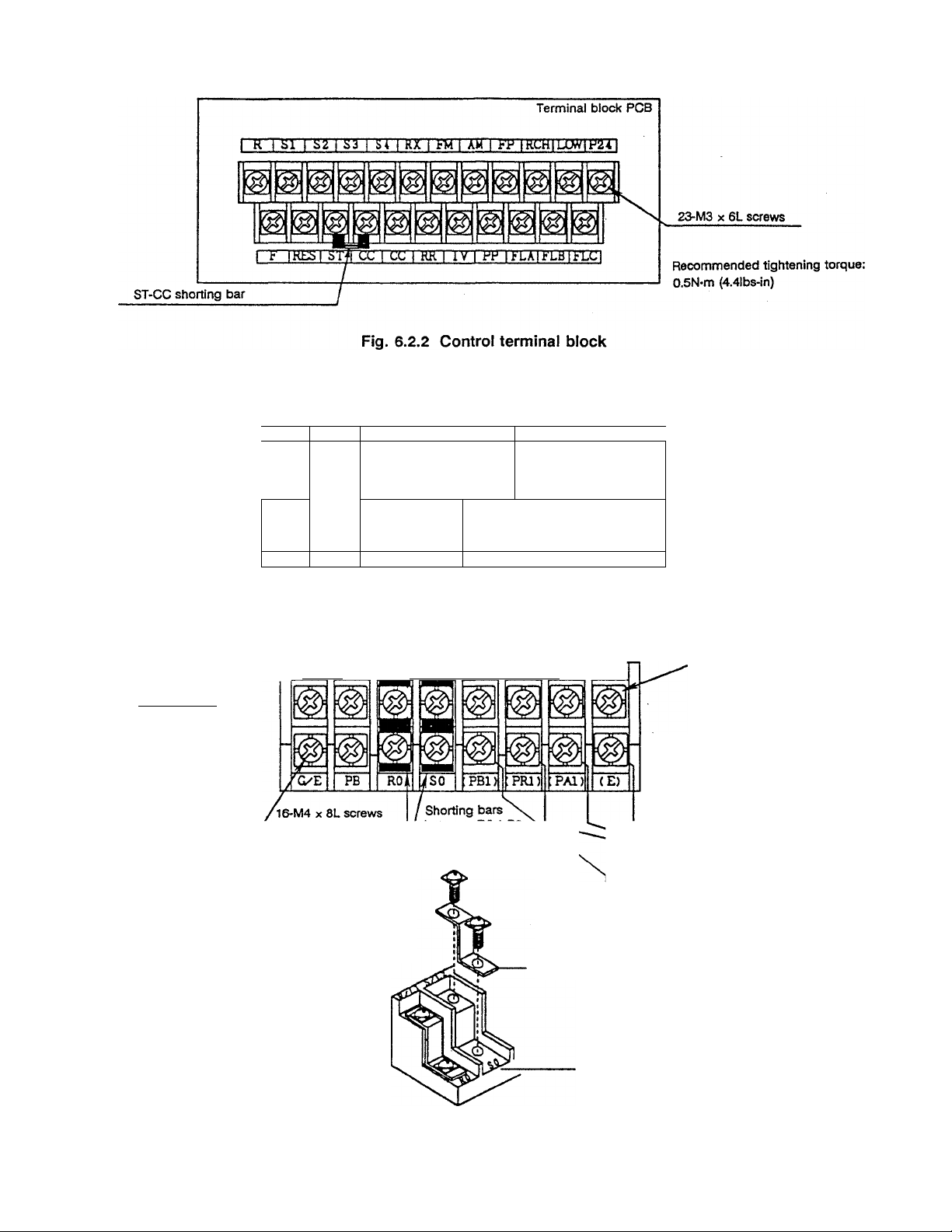
Terminal block cover
FA
R/Ll S/L2 T/L3
U/Tl V/T2 W/T3
Terminal block
CHARGE
o
Charge lamp
(Lights when there is
a charge on the main
circuit capacitors)
3.7kW and smaller units
Removal of shorting bars
Remove the two terminal screws
as shown on the right, and remove
the shorting bar
'e
©
C/E FB
©
POWER SUPPLY
EXT.
RESISTOR
PC PA R/Ll S/L2 TyL3 U/’TL V/T2 W^T3
CONTROL
R SLTPLY
RO SO
MOTOR
INTERNAL RESISTOR
ON , OFF
( PBl)
1 ( PRl) (PAD { E)
Shorting bar
With terminal cover
Recommended tightening torque:
1.2N*m (lllbs-in)
Connected to inverter chassis
Sc-v Connecte
Wired to built-in braking resistor.
When using the buiit-in braking
resistor, change the wiring from
(PR1) to (PB1).
When connecting a separate power
supply to the RO and SO terminals,
always remove the shorting bars,
or the inverter may be damaged.
Fig. 6.2.3 Main circuit terminal block (3.7kW and smaller units)
Terminal block
- 23 -
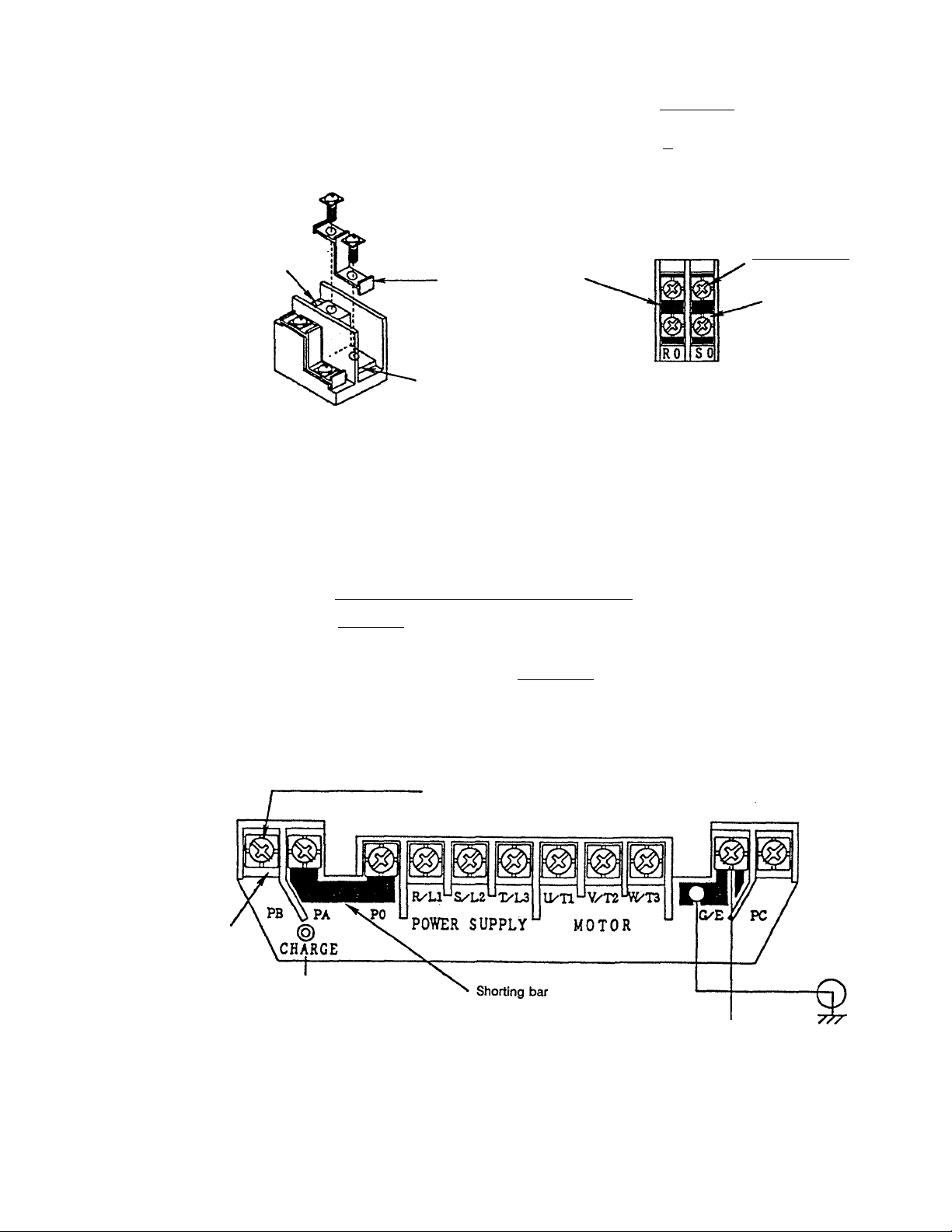
5.5kW and larger units
Removal ot RO and SO terminal
shorting bars
Remove the two terminal screws as
shown below, and remove the
shorting bar.
RO, SO terminal block
for external wiring
Terminal block cover
Terminal block cover
^VftRNI^G]
• ttoMtan
t« Hift éfi to
tto to«rt№
ia.toetwnwL
Terminal block
Shorting bar
Connected to the main circuit
terminals. Do not connect
external wiring to the lower
terminals.
Shorting bar
CON-mOL POWER SUPPLY
200V CLASS
Note) 400V systems are indicated as ’400V CLASS“.
Fig. 6.2.4 Control power terminal block (S.SkW to 30kW units)
4-M4 X 8L screws
With terminal cover
Recommended
tightening torque;
1.2N-m (lllbsH'n)
Terminal block
With terminal cover
r
PB ^ PO ^2 ^3, ^2 % %
200V class!POWER SUPPLY MOTOR © ^
Note) 400V systems are indicated as 1400V CLASS
4-M5 X 10L screvtrs
Charge lamp
(Lights when there is
a charge on the main
circuit capacitors)
Recommended tightening torque
2.4N-m (21lbs-in)
Ground
Connected to
inverter chassis
Fig. 6.2.5 Main circuit terminal block (S.SkW to 7.5kW units)
24
Loading...