


VF-SX
Table of contents
 Loading...
TOSHIBA
E6580496 0
ULTRA-COMPACT
DIGITAL INVERTER
VF-SX
OPERATION MANUAL
JUNE, 1993

TOSHIBA
TOSHIBA VF-SX INVERTER
OPERATION MANUAL
TABLE OF CONTENTS
INTRODUCTION ............................................................ I-l
CHAPTER 1 Inspection Procedure Upon Receipt
...........................
I-I
CHAPTER 2 Proper Environment for Installation
.........................
2-1
CHAPTER 3 External Views and Connection Diagrams
......................
3-1
3.1 External Views.................................................3-2
3.2 Connection Diagrams .......................................... 3-4
CHAPTER 4 Application Precautions
.......................................
4-1
CHAPTER 5 Wiring Guidelines and Warnings
..............................
5-1
5.1 Inverter Wiring................................................5-2
5.2 Installation of a Molded Case Circuit Breaker (HCCB)
........
5-4
5.3 Installation of a Primary Magnetic Contactor (HC)
............
5-5
5.4 Installation of an Output Magnetic Contactor (MC)
............
5-5
5.5 Installation of an External Overload Relay
..................
5-6
5.6 Installation of an Input Reactor...............................5-6
5.7 Incorrect Wiring and Incorrect External Components
..........
5-6
5.8 Basic Wiring Recommendations ................................. 5-7
Chapter 6 Standard Connections ........................................ 6-1
6.1 Examples of Standard Wiring .................................. 6-2
6.2 Terminal Functions ........................................... 6-7
Chapter 7 Parameter Groups
..............................................
7-1
7.1 Definitions of SX Drive Group Parameters
....................
7-2
7.2 Parameter Group Tables
.......................................
7-3
Chapter 8 Basic Operation Theory
........................................
8-1
8.1 Operation of the Touchpad Control Panel
.....................
8-2
8.2 Display Modes.................................................. 8-4
8.2.1 Drive Mode................................................... 8-5
8.2.2 Monitor Mode
.................................................
8-8
8.2.3 Programming Mode............................................8-10
8.2.4 Jogging Mode from the Touchpad..............................8-11
8.3 PANEL/REHOTE Control ........................................ 8-12
8.4 Selection of Stopping Method from the Touchpad
...............
8-12
8.5 Starting the Drive from the Touchpad
..........................
8-14
8.6 Changing Frequency from the Touchpad
..........................
8-16
8.7 Error Reset................................................... 8-17
8.8 Warning Displays
............................................
8-18
8.9 Fault Relay Information ..................................... 8-19

CHAPTER 9 Fundamental Operation Parameters and Functions [GC~ .F] . 9-1
9.1 Setting of Voltage and Frequency Characteristics
............
9-4
9.1.1 Maximum Frequency [fH]
.....................................
9-4
9.1.2 Base Frequency [UL]
.........................................
9-5
9.1.3 Torque Boost [Ub]
...........................................
9-7
9.1.4 V/f Patterns [P t].........................................9-8
9.2 Upper Limit Frequency and Lower Limit Frequency [U L ,L L] 9-9
9.3 Forward and Reverse Run [f,rj
......................
.........
9-10
9.3.1 Operation from the Touchpad ............................... 9-10
9.3.2 Operation Using External Signals
.........................
9-11
9.4 Acceleration and Deceleration
...............................
9-14
9.4.1 Acceleration and Deceleration Time [R C C I },
[dèe / ], [R C C d], [d E C c]..............9-14
9.4.2 Acceleration/Deceleration Pattern [Pt / ], [Pt P] . . 9-15
9.4.3 Selection of Acceleration/Deceleration 1 and 2
[Rd^], [Rd^F]
.......................................
9-17
9.5 Setting of Standard Parameter Groups [ t ^ P]
............
9-19
Chapter 10 Terminal Selection Parameters [GC.S t]
...............
10-1
10.1 Command Mode Selection [ cnodi
.........................
10-2
10.2 Frequency Setting Commands [P fl R d]
...................
10-3
10.3 Parameter Setting Disable Function [PR 0 d]
.............
10-3
10.3.1 Security Considerations and Parameter [PR Od] .... 10-4
10.4 Input Terminal Selection [ I t b]
......................
10-4
10.5 Output Terminal Selection [Otb]
.......................
10-6
10.6 Low Speed Signal Output and Speed Reached Signal Output
[LF], [LFHL], [FrCH], [CCH], irrCH] , 10-7
10.6.1 Low Speed Signal Output Frequency [ i. F] and Speed
Reached Logic Signal [ LFHL]
...................
.........
10-7
10.6.2 Speed Reached Signal Output irCH]
.................
. . . 10-7
10.7 Frequency Setting via Remote Control Signals
..............
10-9
10.7.1 Types of Frequency Setting Signals
.....................
10-10
10.7.2 RR Terminal Input Priority C C ], [ I U I O] . . 10-12
10.8 Frequency Setting Signals [P / ], [F*“P I ] and
[PP], [P —PP]
......................... ....................
10-12
10.9 Jogging Run via Remote Control [ tJ 0 0], [d SEP] 10-14
10.10 Multiple Speed Run [ST.D], [StI — StI] . . 10-17
^_____________________TOSHIBA
______________________

Chapter 11 Protection Parameters [ Gr.Pn
....................
.... 11-1
11.1 Regenerative Discharge Braking Selection [P b] and
Overvoltage Limiting Action Selection [OP 5 b]
.............
11-2
11.2 DC Injection Braking Start-up Frequency [dbF],
DC Injection Braking Voltage [ dbU] t and DC Injection
Braking Time [d b b]..................... .............11-4
11.3 Emergency Stop [EScP]
.....................................
11-6
11.3.1 Emergency Stop from the Touchpad...........................11-6
11.3.2 Emergency Stop Using Remote Control Signals
.............
11-7
11.3.3 Emergency DC Injection Braking Stop Control Time
[fdbfc] ................................................11-8
11.4 Retry [T try]
.............................................
11-8
11.5 Power Control Function [UuC]........................... 11-10
11.6 Electronic Thermal Protective Level [b Hf~] 11-11
11.7 Stall Prevention Function Activation Level [5 fc /.] ... 11-11
11.8 Electronic Thermal Protection Characteristic Selection
[0 L il]
.............................................
11-11
11.9 Retention of Trip [t^CL]
................................
11-11
Chapter 12 Control and Communication Parameters [ 0 f. C C ] 12-1
12.1 Differences Between Startup Frequency and Operation Starting
Frequency....................................................12-2
12.2.1 Start-Up Frequency [F~5t]
.............................
12-3
12.2.2 Operation Starting Frequency [ Frurt]
......................
12-4
12.2.3 Operation Starting Frequency Hysteresis [ FHdS] . . . 12-4
12.3 Jump Frequency and Jump Bandwidths [ F J.H],
[ F J / ] and [ b F <J / ], [ F J d ] and [ b F J (? ].
[ F J 3 ] and [ b F J 3 ] 12-5
12.4 PWM Carrier Frequency [CF] and
Motor Tone Selection [CF5]
.................................
12-6
12.5 Output Voltage Adjustment rPOUb] and Power Voltage
Compensation Function [ ppddi .......................... 12-6
12.6 Automatic Torque Boost [ Rub]
.........................
12-8
12.7 Slip Frequency Compensation [5FC]
.................
12-10
______________________TOSHIBA
_____________________
3

TOSHIBA
Chapter 13 Meter Adjustment Parameters [ Gr.RH] ............. . . . . 13-1
13.1 Meter Connections [FnRfl] .
.
........................ 13-2
13.1.1 Connection of a Frequency Meter [F fl]
..............
13-2
13.1.2 Connection of an Ammeter [R /7]
..........................
13-3
13.2 Frequency Setting Signal [rr—b], [rr—C]
................
13-5
13.3 Universal Unit Multiplication Factor [d 5 P (?]
............
13-7
Chapter 14 General Drive Specifications
..........................
14-1
14.1 Drive Specifications ....................................... 14-2
14.2 External Dimensions ........................................ 14-4
Chapter 15 Options.......................................................15-1
15.1 Input Reactor
..............................................
15-2
15.2 Radio Noise Reduction Filter
..............................
15-2
15.3 Braking Resistor ........................................... 15-2
15.4 Connection Cable ........................................... 15-2
Chapter 16 Error Displays, Explanations, and Remedies
..................
15-1
16.1 Inverter Trip Causes and Remedies
.........................
16-2
16.2 Other Errors and Remedies
...................................
16-4
Chapter 17 Maintenance and Inspection ................................... 17-1
Chanter 18 Storage and Warranty ....................................... 18-1
18.1 Storage..................................................’ ] 18_2
18.2 Warranty...................................................] 18-2
Appendix....................................................... H-1
APPENDIX 1 — TABLE OF TRIP CODES AND WARNING CODES
............
! ! A-2
APPENDIX 2 ~ INPUT TERMINAL INFORMATION AND OUTPUT TERMINAL
INFORMATION
.................................................
A-3
APPENDIX 3 — LEO ALPHANUMERIC CROSS REFERENCE
.....................
A-4

TOSHIBA
i-i
IHTRODUCTIOH
Thank you for purchasing the Toshiba Compact Inverter "TOSVERT VF-SX".
The VF-SX variable speed drive Is a high performance Inverter that has numerous
built-in functions, making It suitable for many applications. This Inverter Is
very easy to program and operate. All instructions are entered via the membrane
keyboard panel (the "touchpad"). The latest technology and features, including
current limit, auto-restart, dynamic braking, and stall prevention are Included.
This product offers flexible operation for numerous applications, and helps
prevent nuisance tripping, even for difficult loads and applications.
Please thoroughly review this manual before attempting use of the VF-SX drive,
so that the features of this drive can be properly applied for each unique
applIcatlon.
Please keep this manual for future reference, operation, and maintenance of the
VF-SX drive.
Always ground the Inverter in accordance with Article 250 of the National
Electrical Code or Section 10 of the Canadian Electrical Code, Part I. The
grounding conductor should be sized In accordance with NEC Table 250-95 or CEC,
Part I, Table 16.
See Chapter 6 for simplified power and control wiring instructions and
recommendations.


TOSHIBA
1-1
CHAPTER 1 Inspection Procedure Upon Receipt

1-2
TOSHIBA
1. Inspect the Toshiba Model VF-SX variable speed drive. Confirm that no
parts have been damaged during transit.
2. Confirm that the model number inscribed on the nameplate is the same as
that ordered.
3. If the inverter will not be placed in service immediately upon receipt,
store the device in a dust free environment. Be sure the room is
ventilated with cool, dry air. Store this device in its original packing
material whenever possible.
4. Every reasonable precaution is taken during the production, packaging, and
shipping of this device to prevent damage to the unit before installation.
If there is any damage upon receipt, contact the dealer and the freight
company immediately.

TOSHIBA
2-1
CHAPTER 2 Proper Environment for Installation

2-2
TOSHIBA
The VF-SX inverter Is a solid state device. Use caution to install the device
in the proper environment, as instructed in the general recommendations shown
below. See Chapter 14 for detailed specifications of the proper operating
environment.
1. Confirm that the input power supply is within +/- 10% of the nominal
voltage. The protective circuit will activate and trip if the permissible
input voltage range is exceeded. Extreme voltage conditions may damage
the inverter.
2. Do not install the inverter in places where high temperature or humidity
are present. Do not install in dusty environments, or environments
contaminated with metal particles or metallic powder.
3. Do not mount the inverter on any device subject to intense vibration.
4. Operate the inverter only in an environment between -10 deg C to 40 deg C.
The inverter generates heat when operating. When it is installed on a
subpanel or backplate be sure there is adequate ventilation on all sides
of the inverter, including the back of the inverter where the heat sinks
are located. In high ambient temperatures it may be necessary to remove
the stick-on seal on the top of the inverter to allow more ventilation
through the Inverter.
Certain electrical equipment, if installed too near the inverter, may
cause malfunctions. Examples of this type of equipment can include:
If a magnetic contactor is installed near the inverter install a
urge suppression device across the coil of the contactor to prevent
surging magnetic fields from interfering with the operation of the
inverter.
Do not install the inverter near fluorescent lighting.
Keep other heat generating electrical equipment, such as resistors
or heaters, away from the inverter.
5.
6.
7.
8.
A.
B.
C.
Always properly ground the inverter chassis to prevent electrical noise
and nuisance tripping. Proper earth ground should not exceed 100 ohms.
Install the inverter ONLY on incombustible subpanels, such as a metal
subpanel. If the inverter is installed on a heat insulating subpanel then
mount the inverter on a metal subpanel first, and attach this assembly to
the insulated subpanel.
Always have at least 10 centimeters free space above and below the
inverter. Always have at least 5 centimeters free space on EACH side of
the inverter. If more than one inverter is mounted in a row, leave at
least 10 centimeters between each drive, from side to side. If fans are
installed in the enclosure or near the drives this space requirement may
be reduced. Consult the Toshiba factory for details.

TOSHIBA
3-1
CHAPTER 3 External Views and Connection Diagrams
3-2
TOSHIBA
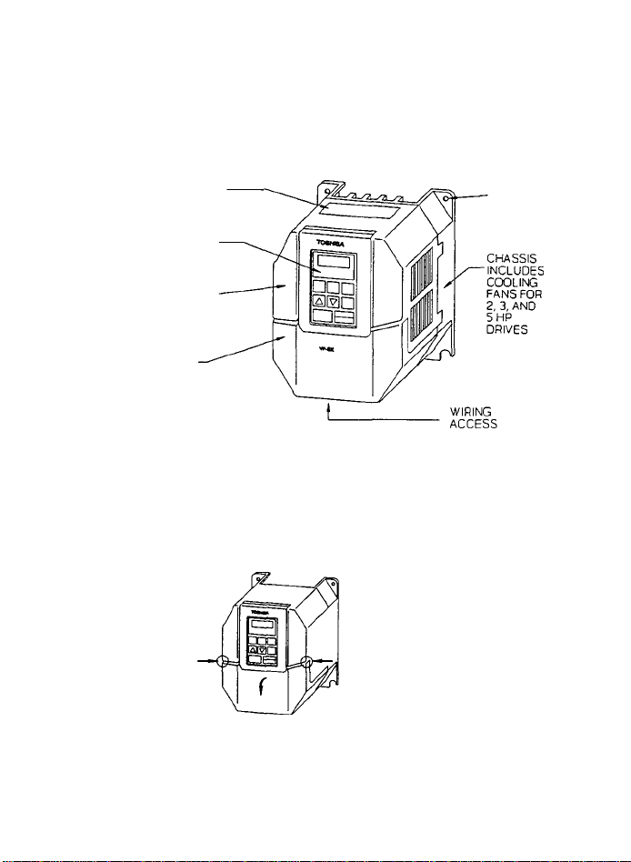
3.1 External Views
REMOVE THIS SEAL
WHEN USING THE
INVERTER IN A HOT
PLACE
TOUCHPAD CAN
BE REMOVED
UPPER COVER
DOES NOT NEED
TO BE REMOVED
UNLESS THE
EXTERNAL SIGNAL
SELECTION
JUMPERS ARE
CHANGED
LOWER COVER MUST
BE REMOVED WHEN
THE TOUCHPAD IS
REMOVED OR WHEN
WIRING IS
CONNECTED TO THE
TERMINALS
FOUR
INSTALLATION
HOLES
PRESS THE LOWER COVER
ON BOTH SIDES (AS
SHOWN) SWULTANEOUSLY.
PULL THE COVER FORWARD,
TO INSTALL THE COVER,
insert the COVER CLASPS
IN THE BOTTOM HOLES,
ROTATE THE TOP OF THE
LOWER COVER BACK INTO
POSTITON, AND GENTLY
PRESS UPPER CLASPS INTO
PLACE

TOSHIBA
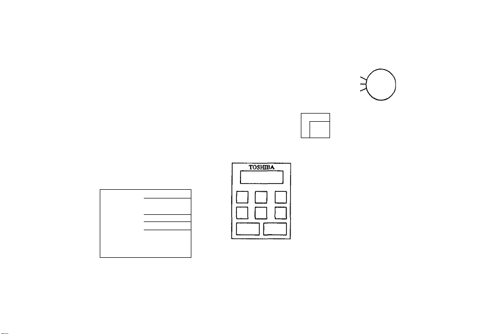
3-3
CONTROL CIRCUIT
TERMINAL BLOCKS
MAIN CIRCUIT
TERMINAL BLOCKS
THESE terminal
BLOCKS ARE FOR
INPUT, OUTPUT,
GROUND, AND
OPTIONAL BRAKING
RESISTOR
CONNECTIONS
LOWER COVER INLET
CONNECTOR FOR
TOUCHPAD OR
TOUCHPAD EXTENSION
CABLE
SCREW HOLD FOR
TOUCHPAD
TO REMOVE UPPER
COVER, INSERT A
BLADE SCREWDRIVER
UNDER 4 CLASPS
AND LIFT GENTLY
CHARGE I AMP
DO NOT CHANGE WIRING
OR REMOVE UPPER
COVER WHEN LIT
SINGLE PHASE
MCCB
POWER » ►
SUPPLY ^
SmOLE PHASE * ^
2Ù0.230VAC, 50/60HZ
RESET
FORWARD
REVERSE'
: : ¿‘ÎNTÊWloâC
.......
....
■
MULTI- / : 1 f ■■■■
FUNCTION T
T
.............
........
SIGNAL \ ! ■...............
INPUT ^ ‘
..........................
ANALOG INPUT
. \AUtO :
^
AUTO +
REFERENCE
] i
D
PA PB
VF-SX
RST
F
R
ST
cc
SSl
JOG/SS2
BX/SS3
AD2
PP
RR
CC
T1(U),
T2(V),
T3(W)
FLA
FAULT
FLB
' FLC
FM/AM.
CC
P24
LOW/LL
RCIVUL,
GND(E)
M
FAULT SIGNAL
OUTPUT
FREQUENY/CURRENT
r*‘™X"*:i.SipNAL
I \SCAl£r
• ; 1mA
+24VÒC
T MULTI- FUNCTION
i SIGNAL OUTPUT
w
N»
O
O
CD
n
D»
la
"t
A>
B
(/)
CO
MAX
TOTAL
♦DBR NOT AVAILABLE ON SINGLE PHASE 1/8, 1/4HP UNITS.

THREE PHASE
MCCB
DBR*
POWER
--------------
SUPPLY
--------------
THRBBPHÂSB ’ *
200 - 230VAC, 5(V60Hz
RESET
* FORWi^
i « RÌBvSiSÈ''
! isINTERLOCK
....
MULTI- / ; ± -
FUNCTION f ;
SIGNAL \ '
..........
INPUT ^
................
..............
ANALOG INPUT
;vAUTO
ÌìjìanrTv;;],
iAUTO
¡REFERENCE
-.JÎÏ7
+ .¡.j..
L1(R)
U(S)
L3CD
RST
F
R
ST
cc
SSI
JOG/SS2
EX/SS3
AD2
PP
- RR
; CC
}■ IV
PA PB xi(U)
T2(V)
T3(W)
FLA
VF-SX
FAULT
RELAY.
■fi
FLB
FLC
FM/AM -
□ □ □
□ □ □
cc
P24
LOW/LL
RCHAJL
GND{E)
7T
M
FAULT SIGNAL
OUTPUT
FREQUENY/CURRENT
-■‘•FtnX—
: ¡SCALE/'
I ;AT
: MmA
i +24Vdc
..
f-
...
MAX
TOTAL
MULTI- FUNCTION
SIGNAL OUTPUT
*DBR NOT AVAILABLE ON THREE PHASE 1/8, I/4HP UNITS.
O
C/3
s
5
>


TOSHIBA
4-1
CHAPTER 4 Application Precautions

4-2
TOSHIBA
1. If the drive is very lightly loaded (approximately 5*) or if the inertia
of the driven load is very small, the drive may become unstable. The
result could be abnormal vibration or overcurrent trip. If this condition
persists lower the PWM carrier frequency (parameter [C F]). See Chapter
12 for instructions.
2. Unstable results may occur if:
A. The output rating of the drive is less than the output rating of the
motor.
B. The drive is used with a motor with special ratings, such as an
explosion proof motor, or a motor specially built for high inertia
applications.
C. The drive is used with a pulsing load, such as a load requiring
repeated piston type operation.
3. The motor will coast to stop if the power is lost. If an immediate stop
or very quick deceleration of the motor is required use an auxiliary brake
device. Select the appropriate stopping method as described in Chapter 11
for an emergency stop.
4. GROUNDING
The inverter should be grounded in accordance with Article 250 of the
National Electrical Code or Section 10 of the Canadian Electrical Code,
Part I. The grounding conductor should be sized in accordance with NEC
Table 250-95 or CEC, Part I, Table 16.

TOSHIBA
5-1
CHAPTER 5 Wiring Guidelines and Precautions

5-2
TOSHIBA
This chapter of the manual discusses some of the basic wiring configurations and
external devices commonly associated with the installation and application of
variable speed drives. Local codes, specifications, requirements, and operating
conditions may require the addition of other devices or modifications to the
following basic recommendations.
5.1 Inverter Wiring
(Refer to Figure 5.1 and 5.2)
1. It can be difficult to remove the upper cover after wiring, so change the
jumper selectors J1 or J2 on the internal PC board for "external signal
selection" before wiring the inverter. See Chapter 6 for the approximate
location of jumpers J1 and J2 inside the drive.
When a signal between 0 to 5V is used as frequency signal, switching the
jumper is necessary. Refer to Chapter 10, Table 10-9 for details.
2. Always turn the main line power OFF and confirm that there is no voltage
present with a testing tool before connecting power, motor leads, or
control wires.
3. WTOJIN^ Wait until the "CHARGE" lamp has turned off before working on
the drive. An internal capacitor stores electrical charge in the inverter
and electrocution may result due to inadvertent contact with this
capacitor. Do not touch the terminals or remove the cover while the
"CHARGE" lamp is on. This indicator is located in the lower right-hand
side of the drive near the terminal blocks, and it is a brightly lit red
LED when the drive is fully charged.
4. WARNING: Do not wire input power to the output terminals (U, V, W) of the
drive, this will damage the drive. Before energizing, confirm that motor
leads are attached to terminals U, V, and W and that the main power leads
are attached to terminals R, S, and T.
5. Exercise caution when wiring the control signals, as shown.
A. Install a surge suppressor on any electromagnetic coil on any
contactor wired to the drive. This includes line and load side
contactors.
B. Use shielded wire or twisted pair wire for control circuit wiring.
Keep this wire isolated from power wire.
C. Always isolate the input control signals from the main power wiring.
This restriction applies to all control terminals except FLA, FLB,
and FLC.
6. Wire sizes:
A. For wire to an ammeter, wire to a frequency meter, and wire carrying
input speed reference signals, use at least 16 gauge shielded wire.
B. For all other control wiring, use at least 12 gauge PVC coated wire.

TOSHIBA
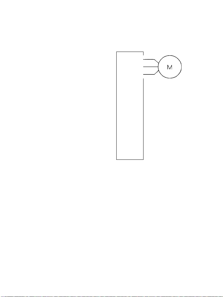
, 5-3
Inverter Main Circuit Terminal Block
Figure 5.1 Main Circuit Wiring
5-4
TOSHIBA
MCCB
MC
—oln
---
L_o o
----
—
/^jr^MCCB-Trip Coil
R
U
s
V
T
W
F
FLB
R
FLC
CC
FLA
Forward
Run/Stop
h
Reverse
Run/Stop
Figure 5.2 Simplified Power and Control Wiring
5.2 Installation of a Molded Case Circuit Breaker (MCCB)
1. Install a molded case circuit breaker (HCCB) on the line side of the drive
for protection of the incoming power wiring only.
2. Turn the drive ON and OFF via control devices or the touchpad whenever
possible, and not by manual operation of the HCCB or MC. Use the control
terminals F. R, and CC to receive control signals from the appropriate remote
control devices.

TOSHIBA
5-5
5.3 Installation of a Primary Magnetic Contactor (MC)
1. Install a magnetic contactor (HC) on the line side of the inverter to prevent
restart after either a loss of power, a trip of an external overload relay, or
an operation of the internal drive protective device.
2. The VF-SX has an internal fault detection relay. The HC can be opened when
the inverter protective circuit operates by connecting this contact point to the
primary MC operation circuit.
3. The inverter can be used without an HC. In this case use a shunt trip style
main breaker (MCCB) and open the main circuit by tripping the breaker when the
inverter protective circuitry operates.
4. When using a braking resistor with an overload relay, install an HC or an
MCCB with shunt trip on the line side of the inverter. Connect these devices so
that the power circuit will open when the internal fault detection relay (Ft) or
externally installed overload relay operates. Emergency stop is also possible
by connecting the overload relay contact point between the terminals of SS3 (EX)
and CC of the inverter. See Chapter 11 for details of the Emergency Stop
parameter.
5. Use control signals on terminals F, R, and CC for frequent starting and
stopping. Avoid turning the inverter on and off with the primary HC.
6. Always install a surge suppressor across any contactor coil.
5.4 Installation of an Output Magnetic Contactor (MC)
1. Avoid starting and stopping the motor with an output contactor (HC) installed
between the inverter and the motor. Excessive surge currents could damage the
output devices of the drive. Use control signals on terminals F, R, and CC
instead.
2. For Bypass Operation; Be sure the motor has stopped and the drive is OFF
before turning on the bypass contactor to run the motor directly from line power.
Use an external timer, PLC, or similar device as required. Always make sure that
the bypass contactor does not allow voltage to backfeed into the inverter output
terminals.

5-6
TOSHIBA
5.5 Installation of an External Overload Relay
1. An electronic overload relay is standard on the VF-SX drive. However, for
the following applications Toshiba recomtnends Installing an overload relay that
coordinates with the internal solid state relay and the motor connected to the
drive. Connect the external relay between the drive and the motor.
A. When using a motor with non-standard current ratings, or the motor
ratings are not comparable to standard duty motors.
B. When operating a single motor smaller than the rating of the drive.
C. When operating several motors simultaneously from the drive. In this
case Install an overload relay on EACH motor.
2. When applying the VF-SX drive to a constant torque load, change the
electronic overload characteristics, or Install a separate overload relay. See
Chapter 11, Parameter [ bHrj.
3. When a motor continuously runs at low speeds it is recommended to use a motor
with an Internal overload relay, for additional protection.
5.6 Installation of an input Reactor
An input reactor Is used to suppress high frequency elements and sudden changes
In power fluctuations. Install an Input reactor when the Inverter Is connected
to electrical systems with the any of the following characteristics:
1. When the power capacity Is 200 KVA or more and the power capacity is
10 times or more than the Inverter capacity.
2. When the Inverter Is connected to the same system as a thyristor
commutation type controller.
3. When the inverter Is wired to an electrical system which also
contains a distortion source such as an arc furnace or a large
capacity inverter.
5.7 Incorrect Wiring and Incorrect External Components
WARHINS:
DO NOT INSTALL A POWER FACTOR IHPROVEHENT CAPACITOR ON THE INVERTER INPUT OR
OUTPUT. Current and voltage surges associated with the use of power factor
capacitors can damage the drive components.
If power factor correction is required add an optional input line reactor to
correct power factor.
TOSHIBA
5-7
Radio Freouencv Interference
During operation of the drive there may be noise generated by the drive in the
frequency range associated with radio transmission signals. This noise may
adversely affect sensitive electronic equipment near the drive. If this
condition persists install a RF/EMI (Radio Frequency or Electromagnetic
Interference) filter on the input to the drive. Shield the motor leads in
metallic conduit. These steps will reduce radio frequency interference.
Contact Toshiba for details, or see Chapter 15.
WARWIH6:
Do not operate or energize the inverter before checking between the motor and the
inverter for mis-wiring or short circuits in the motor. Do not operate the drive
if the motor is shorted. Do not ground the neutral point of the motor star
winding.
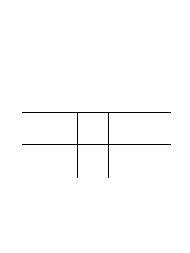
5.8 Basic Wiring Recommendations
TABLE 5-1: BASIC WIRING RECOHMENOATIONS
DRIVE MODEL VFSX- 2001UP
2002UP 2004UP
2007UP
2015UP1
2022UP12037UP1 1
KW RATING 0.1 0.2
0.4 0.75
1.5
2.2 3.7 1
HP RATING
1/8 1/4
1/2
1 2
3 5 j
MCCB SIZE 5 A
5 A 5 A 10 A
15 A 20 A
30 A 1
HC AMPS (1) 12 A
12 A 12 A
12 A 12 A
12 A
18 A 1
OL RELAY RATING 0.7 A
1.3 A 2.3 A
4.2 A
6.6 A
9.3 A 15 A 1
POWER WIRE SIZE 12 GA
12 GA
12 GA
12 GA 12 GA
12 GA 10 GA 1
CONTROL WIRE SIZE 18 GA
18 GA
18 GA 18 GA
18 GA
18 GA 18 GA 1
WIRE SIZE FOR
REGENERATIVE
BRAKING RESISTOR
N/A N/A 14 GA
14 GA
12 GA 12 GA 12 GA 1
NOTES:
1.
2.
3.
4.
Always use a surge suppression device on the coil of the MC contactor.
Use shielded cable on control circuits. See Figure 5.2.
Use 10 gauge wire or larger for ground circuit.
Power wire sizes in table above are minimum size. For cable lengths over
100 feet, or where voltage drops may cause application problems, larger
wire may be required.


TOSHIBA
6-1
Chapter 6 Standard Connections
6-2
TOSHIBA
The items printed in Italics in this chapter are Paraaeter names.
Refer to Chapter 7 for a list of all parameter names and Chapters 8 through 13
for instructions to set or adjust the parameters.
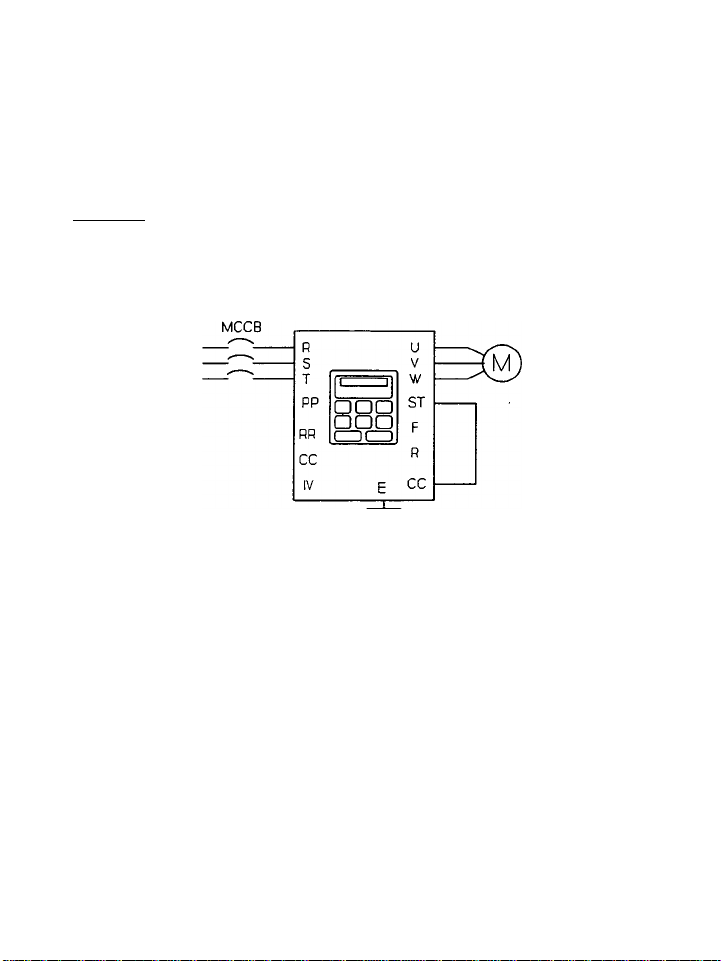
6.1 Examples of Standard Wiring
Example 1: To set the operation frequencies, and conduct forward/reverse run
and/or decelerating stop from the touchpad.
5X DRIVE
Figure 6.1
Setting: In the parameter group [Ci~. 5 t ] the Coaaand Mode Selection is set
to 3 (control terminal or touchpad input). Also, in the same parameter group,
the Frequency Setting Mode Selection is set to 3 (control terminal or touchpad
input). All Model VF-SX drives are shipped with these settings as the factory
default settings.
In Figure 6.1 above:
1. Incoming power is 200-230 volts, three phase, 50 or 60 Hz.
2. A factory installed jumper is present between terminals ST and CC.
3. All drive operation is from the touchpad control panel.
TOSHIBA
6-3
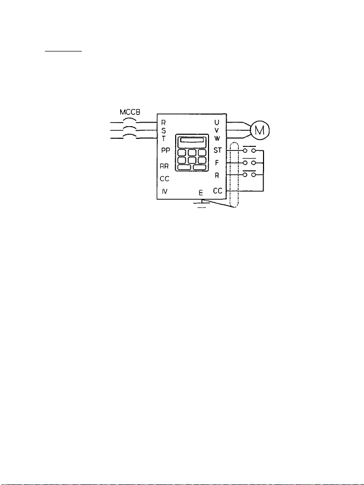
Example 2: To set the operation frequencies from the touchpad, and conduct
forward/reverse run, decelerating stop, and/or coast!ng-to-stop with external
signals.
5X DRIVE
Figure 6.2
Setting; In the parameter group [0 l~. 5 t ] the Command Mode Selection is set
to 3 (control terminal or touchpad input). Also, in the same parameter group
the Frequency Setting Mode Selection is set to 2 (only touchpad input valid).
In Figure 6.2 above:
1.
2.
3.
4.
Incoming power is 200-230 volts, three phase, 50 or 60 Hz.
When the ST-CC contact is open the drive will "Coast-to-Stop".
When the ST-CC contact is closed, and the F-CC contact is closed the
drive will run "Forward". If the F-CC contact is opened the drive
will decelerate stop.
When the ST-CC contact is closed, and the R-CC contact is closed the
drive will run "Reverse". If the R-CC contact is opened the drive
will decelerate stop.
Loading...