


6 F 3 B 0 3 6 0
TOSLINE-S20
Active Star Coupler(ASC25)
Instruction Manual
REQUIREMENTS
∙Keep this instruction manual where it can be easily referred to by users and those responsible for the equipment.
∙Read this instruction manual carefully before using the equipment.
∙After this instruction manual has been read, keep it beside the equipment.
Sep

TOSLINE-S20 Active Star Coupler (ASC25) Instruction Manual |
6F3B0360 |
|
|
Table of Contents |
|
1. |
Introduction ............................................................................................................... |
3 |
|
2. |
Overview ................................................................................................................... |
5 |
|
3. |
System Configurations.............................................................................................. |
7 |
|
4. |
Outline of Functions .................................................................................................. |
9 |
|
5. |
Specifications .......................................................................................................... |
11 |
|
6. |
Hardware................................................................................................................. |
13 |
|
|
6.1 |
Product construction................................................................................... |
13 |
|
6.2 |
External dimensions ................................................................................... |
13 |
|
6.3 |
Component identification ............................................................................ |
14 |
|
6.4 |
Function setting switch ............................................................................... |
15 |
|
6.5 |
LED display................................................................................................. |
17 |
|
6.6 |
Optical connector........................................................................................ |
18 |
|
6.7 |
Terminal block............................................................................................. |
19 |
|
6.8 |
Fuse holder ................................................................................................. |
20 |
7. |
Start up and Power down methods......................................................................... |
21 |
|
|
7.1 |
Start up method .......................................................................................... |
21 |
|
7.2 |
Power down method ................................................................................... |
21 |
8. |
Precautions on using Active Star Coupler .............................................................. |
23 |
|
9. |
Installation and Wiring............................................................................................. |
25 |
|
|
9.1 |
Method for mounting the main unit............................................................. |
25 |
|
9.2 |
Connection of optical fiber cables (cords) .................................................. |
27 |
|
9.3 |
Optical parts................................................................................................ |
28 |
|
9.4 |
Precautions on handling optical fiber and optical connector...................... |
30 |
|
9.5 |
Method of optical connector assembly....................................................... |
32 |
|
9.6 |
Procedure of design for laying optical fiber cables .................................... |
36 |
TOSLINE S20 |
1 |

9.7 |
Precautions on ordering cables/cords |
........................................................38 |
9.8 |
Precautions on laying cables...................................................................... |
39 |
2 |
ASC25 Instruction Manual |

TOSLINE-S20 Active Star Coupler (ASC25) Instruction Manual |
6F3B0360 |
1.Introduction
The brochure is an instruction manual for Active Star Coupler (ASC25) which is a modified version of general use Active Star Coupler (ASC22). The Active Star Coupler (ASC25) is specially designed to connect TOSLINE-S20 data communication network with a station provided with F07 Type Optical Connector, such as TOSVERT-μ/S250W/W Drive Station.
Instruciton manuals for other TOSLINE-S20 components are listed below. System designers, device designers, and maintenance personnel using a TOSLINE-S20 network should refer to these manuals for information about how these components can be used in a TOSLINES20 network.
∙ |
T2/T3 stations |
6F3B0354 |
∙ SIF (Serial Interface) station |
6F3B0352 |
|
∙ |
VME Bus station |
6F3B0353 |
∙ |
Loader software S-LS |
6F3B0351 |
∙ |
PLC-5 station |
6F3B0355 |
∙ Loader software S-LS (for windows) |
6F3B0357 |
|
TOSLINE S20 |
3 |

4 |
ASC25 Instruction Manual |
TOSLINE-S20 Active Star Coupler (ASC25) Instruction Manual |
6F3B0360 |
2.Overview
The Active Star Coupler is used for distributing fiber optic signals in a TOSLINE-S20 network.
The TOSLINE-S20 is a Bus-style transmission system. If the power is off in one of the stations on this bus, communication is not possible before or after that station.
To prevent this from happening, an Active Star Coupler can be used.
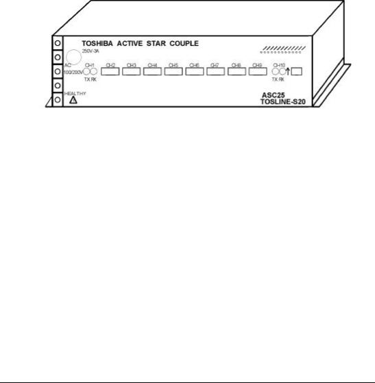
If the Active Star Coupler is used, a station that is off will have no effect on the rest of the transmission system. The Optical Connector Board of the Active Star Coupler has ten ports (CH1 through CH10), in which CH1 and CH10 adopt FC Type connector same to the general version of Active Star Coupler (ASC22). Other ports, CH2 through CH9, adopt the JIS-F07 Type connectors which are mounted to TOSVERT-μ/S250W/W drive station, etc.
Appearance of the Active Star Coupler is shown below.
Figure 2.1
TOSLINE S20 |
5 |

6 |
ASC25 Instruction Manual |

TOSLINE-S20 Active Star Coupler (ASC25) Instruction Manual |
6F3B0360 |
3.System Configurations
Adoption of the Active Star Coupler provides a system configuration illustrated below.
(1)Basic configuration
The maximum applicable number of F01 (FC) Type connector stations is two.
The maximum applicable number of F07 Type connector stations is eight.
F01: F01 (FC) Type station
F07: F07 Type station
Figure 3.1
(2)Active Star Coupler daisy-shain connection
The maximum applicable number of ASCs in daisychain connection is nine.
Figure 3.2
TOSLINE S20 |
7 |

8 |
ASC25 Instruction Manual |
TOSLINE-S20 Active Star Coupler (ASC25) Instruction Manual |
6F3B0360 |
4.Outline of Functions
(1)Basic functions
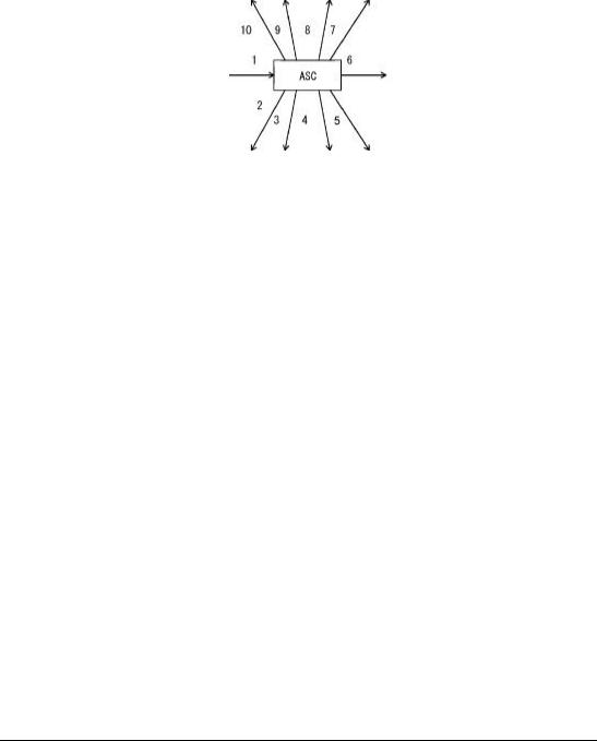
When the Active Star Coupler receives a signal from one channel among ten of them, it
tramsmits this signal (unchanged) from its remaining nine ports.
The drawing given below illustrates the case that data input from Port 1, and the data are output from ports 2 through 10.
Data entered from Port 1
Data generated to Ports 2 through 10
Figure 4.1
(2)Function of preventive measures to single-wire breaking
The function is effective to CH1 and CH10. Able/Disable of the function is selected by a
switch.
In the case that the function is brought into "Able" mode, the transmission on TX side is stopped about 400 ms after the detection of wire breaking at RX side.
* On using the function, refer to 8.(1) "Precautions on the Preventive Measures to Single-Wire Breaking".
(3)Function of status display
Since the conditions of power source and of transmission are confirmed by the turning ON/OFF of the respective LEDs, the function is useful in case of accident occurrence.
For detail of the display, refer to 6.5 "LED Display".
(4)Function of optical level identification
Manipulation of switch makes the optical module output continuously illuminate. The
function is useful to check the optical level at terminals during the cable laying work. For detail of the switch setting, refer to "6.4 Function setting switches".
(5)Function of automatic test operation
The function is used in quality control in the production and test processes. During normal operation, turn the switch to "OFF" position.
For detail of switch setting, refer to "6.4 Function setting switches".
TOSLINE S20 |
9 |
10 |
ASC25 Instruction Manual |

TOSLINE-S20 Active Star Coupler (ASC25) Instruction Manual |
6F3B0360 |
5.Specifications
The section describes the specifications of the Active Star Coupler.
(1)General specifications
General specifications of Active Star Coupler are given below.
|
Item |
Specification |
||
|
Voltage |
Rating |
100/110 V AC, 50/60 Hz |
|
|
|
|
200/220 V AC, 50/60 Hz |
|
|
|
Fluctuation range |
85 to 132 V AC, 47 to 66 Hz |
|
Power |
|
|
170 to 250 V AC, 47 to 66 Hz |
|
Supply |
Power consumption |
about 10 VA |
||
|
Retentive power interruption |
Resuming to normal operation within 10 ms |
||
|
Insulation rating |
1500 V AC for 1 minute |
||
|
Fuse rating |
250V-3A |
||
|
Tempe- |
Operating |
0 to +55°C (unit ambient temperature) |
|
|
rature |
temperature |
|
|
|
|
Storage |
−20 to +75°C (unit ambient temperature) |
|
|
|
temperature |
|
|
Environ- |
Humidity |
20 to 90% RH, no condensation |
||
ment |
Vibration |
Conforming to JIS C0911 |
||
|
|
|
∙ Power OFF, Frequency 16.7 Hz, Displacement 3 mm |
|
|
Atmosphere |
Free from corrosive gas |
||
|
Dust |
Not more than 1 mg/m3 |
||
|
Ground |
Grounding resistance 100Ω or less |
||
External dimensions |
390 (W) × 200 (D) × 70 (H) mm |
|||
Weight |
|
|
approximately 3.0 kg |
|
Cooling |
|
|
Natural air cooling |
|
Installation position |
Horizontal (unacceptable of upside down or vertical |
|||
position) |
||||
|
|
|
||
|
|
|
Table 5.1 |
|
TOSLINE S20 |
11 |

(2)Functional specifications
The functional specifications of the Active Star Coupler are listed below.
Item |
|
|
|
Description |
|
|
|
|
|
|
|
Number of connectable |
Max. 10 |
|
|
|
|
stations |
|
|
|
|
|
|
for FC Type |
Silica glass optical fiber cable (JIS C6820) |
|||
Applied optical fiber |
connector |
GI 50/125 μm (core dia./clad dia.) |
|||
for F07 Type |
H-PCF (hard clad silica glass core fiber) cable |
||||
|
|||||
|
connector |
SI Model 200/230μm (core dia./clad dia.) |
|||
|
Station to Star Coupler |
: Max. 1 km |
|||
Transmission distance |
Star Coupler to Star Coupler : Max. 1 km |
||||
|
Total system |
|
|
: Max. 10 km |
|
Number of daisy-chain |
Max. 9 |
|
|
|
|
connection of Star |
|
|
|
|
|
Couplers |
|
|
|
|
|
Connectable apparatus |
TOSLINE-S20 fiber optic network stations. |
||||
|
"ON" during normal operation |
||||
HEALTHY contact (Relay |
Contact rating |
|
|
|
|
Voltage: 250 V AC |
Current: max. 1 A |
||||
contact) |
Voltage: 24 V DC |
Current: max. 1 A |
|||
|
|||||
|
Voltage: 5 V AC/DC |
Current: min. 10 mA |
|||
Table 5.2
12 |
ASC25 Instruction Manual |
 Loading...