


 Loading...
E6581738
TOSVERT VF-MB1/S15
PROFIBUS-DP Option Function Manual
PDP003Z
NOTICE
1.Read this manual before installing or operating. Keep this instruction manual on hand of the end user, and make use of this manual in maintenance and inspection.
2.All information contained in this manual will be changed without notice. Please contact your Toshiba distributor to confirm the latest information.

|
|
|
E6581738 |
|
|
||
Contents |
|
||
1. |
Introduction .............................................................................................................................................. |
1 |
|
2. |
Connection Information............................................................................................................................ |
6 |
|
|
2.1. |
Exterior features ........................................................................................................................... |
6 |
|
2.2. |
Status indicator ............................................................................................................................ |
7 |
|
2.3. |
VF - MB1/S15 Communication parameters ................................................................................... |
8 |
3. |
Profile |
....................................................................................................................................................... |
9 |
|
3.1. ...................................................................................................................................... |
Telegram |
9 |
|
3.2. ............................................................................................................STW Control Word Data |
10 |
|
|
3.3. ..............................................................................................................ZSW Status Word Data |
11 |
|
|
3.4. ............................................................................................................................ |
State Machine |
13 |
|
3.5. ........................................................................................Access to the PROFIBUS parameter |
15 |
|
|
3.6. .................................................................................................... |
PROFIBUS parameter (PNU) |
16 |
|
3.7. ............................................................................................Access to VF-MB1/S15 parameter |
18 |
|
4. |
Vendor ..............................................................................................................................Spec. Profile |
20 |
|
|
4.1. ................................................................................................................................. |
How to use |
21 |
|
4.2. ............................................................................The overview of the VF-MB1/S15 parameter |
22 |
|
5. |
Diagnostic .............................................................................................................................................. |
29 |
|
6. |
DP-V1 .......................................................................................................................................function |
30 |
|
|
6.1. .............................................................................Example1. Read the PROFIdrive parameter |
31 |
|
|
6.2. ........................................................................Example 2. Change the PROFIdrive parameter |
32 |
|
|
6.3. ..........................................................................Example 3. Read the VF-MB1/S15 parameter |
33 |
|
|
6.4. ......................................................................Example 4. Change the VF-MB1/S15 parameter |
34 |
|
7. |
PROFIBUS ....................................................................................................Local/Remote Operation |
35 |
|
8. |
GSD file.................................................................................................................................................. |
35 |
|
9. |
Appendix................................................................................................................................................ |
36 |
|

E6581738
1. Introduction
Thank you for purchasing the PROFIBUS-DP option “PDP003Z” for the VF-MB1/S15. Before using the PROFIBUS-DP option, please familiarize yourself with the product and be sure to thoroughly read the instructions and precautions contained in this manual. This option needs the option adaptor to connect VF-S15 which type form is SBP009Z. Please match here and buy it when SBP009Z is not at hand yet.
In addition, please make sure that this manual and “Installation Manual” is delivered to the customer, and keep this function manual in a safe place for future reference or drive/interface inspection.
This manual describes the supported functions for the “PDP003Z”.
In conjunction with this manual, the following manuals are supplied by Toshiba, and they are essential both for ensuring a safe, reliable system installation as well as for realizing the full potential of the “PDP003Z”:
- TOSVERT VF-MB1 Instruction Manual................................................ |
E6581697 |
- TOSVERT VF-S15 Instruction Manual................................................. |
E6581611 |
- TOSVERT VF-MB1/S15 communication option Precautions Manual· E6581739
- 1 -
E6581738
Safety precautions
On the drive and in its instruction manual, important information is contained for preventing injuries to users and damages to assets and for proper use of the device. Read the instruction manual attached to VF-MB1/S15 along with this instruction manual for completely understanding the safety precautions and adhere to the contents of these manuals.
Explanation of markings
Marking |
Meaning of marking |
Warning |
Indicates that errors in operation may lead to death or serious injury. |
|
Indicates that errors in operation may lead to injury (*1) to people or that these errors Caution may cause damage to physical property. (*2)
(*1) Such things as injury, burns or shock that will not require hospitalization or long periods of outpatient treatment.
(*2) Physical property damage refers to wide-ranging damage to assets and materials.
Meaning of marking
Indicates prohibition (Don't do it).
What is prohibited will be described in or near the symbol in either text or picture form.
Indicates something mandatory (must be done).
What is mandatory will be described in or near the symbol in either text or picture form.
Indicates warning.
What is warned will be described in or near the symbol in either text or picture form. Indicates caution.
What the caution should be applied to will be described in or near the symbol in either text or picture form.
- 2 -
E6581738
■ General Operation
|
|
|
Warning |
|
|
|
▼ Never disassemble, modify or repair. |
|
|
|
|
|
|
|
Doing so could result in electric shock, fire and injury. For repairs, call your sales |
|
|
|
|
|
|
|
|
Disassembly |
|||
prohibited |
agency. |
||
|
|
|
▼ Do not attach this option to any drive other than the VFMB1/S15. |
Prohibited |
Doing so could result in electric shock or fire. |
||
|
|||
▼When the drive is energized, never detach the this option from the VFMB1/S15. Doing so could result in electric shock.
▼Don't place or insert any kind of object into the PDP003Z (electrical wire cuttings, rods, wires).
Doing so could result in electric shock or fire.
▼Do not allow water or any other fluid to come in contact with the PDP003Z. Doing so could result in electric shock or fire.
▼ Turn off the VFMB1/S15 when installing and wiring this option.
Mandatory ▼ If the drive begins to emit smoke or an unusual odor, or unusual sounds, immediately turn power off.
If the equipment is continued in operation in such a state, the result may be fire. Call your local sales agency for repairs.
■ Transportation & installation
 Warning
|
▼ Do not operate the drive if it is damaged or any component is missing. |
Prohibited |
Doing so could result in electric shock or fire. Call your local sales agency for repairs. |
|
▼Do not place any inflammable substances near the VFMB1/S15 drive. If an accident occurs in which flame is emitted, this could lead to fire.
▼Do not install in any location where the drive could come into contact with water or other fluids.
Doing so could result in electric shock or fire.
▼When installing this option, be careful not to touch the leads from parts on the reverse side of its circuit board.
Doing so could result in injury.
|
▼ Operate under the environmental conditions prescribed in the instruction manual. |
Mandatory |
Operations under any other conditions may result in malfunction. |
|
- 3 -
E6581738
■ Wiring
 Warning
|
▼ Shut off power when installing and wiring this option. |
|
Mandatory |
Wait at least 15 minutes and check to make sure that the charge lamp (VFMB1/S15) is |
|
no longer lit. |
||
|
▼Electrical construction work must be done by a qualified expert.
Installation or connection of input power by someone who does not have that expert knowledge may result in fire or electric shock.
■ Operations
 Warning
|
▼ Do not touch switches when the hands are wet and do not try to clean the drive with a |
|
Prohibited |
damp cloth. |
|
Doing so could result in electric shock. |
||
|
▼Do not pull on any cable it self.
Doing so could result in damage or malfunction.
■Cautions for the communication
 Warning
|
▼ Do not set the value that exceeds an effective range as data. |
|
Prohibited |
The motor may suddenly restart or stop and that could result in injury. |
|
|
||
|
|
|
|
▼ Check PROFIBUS state (using below status word bit) when the option unit is |
|
Mandatory |
deactivated by an unusual event such as an operating error, power outage, failure, etc. |
|
- ZSW Status Word Bit 3 (Fault), Bt 7 (Warning) |
||
|
||
|
(The communication error occurs when "1" as value or this value cannot be read.) |
|
|
Deactivated option unit may cause an accident, if the PROFIBUS state is not checked. |
▼Make sure that the operation signals are STOP before clearing the drive’s fault. The motor may suddenly start and that may result in injuries.
■ Disposal
 Caution
|
▼ For safety's sake, do not dispose of the disused drive yourself but ask an industrial |
|
Mandatory |
waste disposal agent (*). |
|
If the collection, transport and disposal of industrial waste is done by someone who is |
||
|
||
|
not licensed for that job, it is a punishable violation of the law. (Laws in regard to |
|
|
cleaning and processing of waste materials) |
|
|
(*) Persons who specialize in the processing of waste and known as “industrial waste |
|
|
product collectors and transporters” or “industrial waste disposal persons.” |
- 4 -

E6581738
Notes on use
Notes
▼Do not install the drive where the temperature or the humidity will change rapidly.
▼Keep a distance of 20cm or more between the drive 's power cable and the data transmission cable.
Or the drive might malfunction because of noise.
▼Insert a magnetic contactor or similar device between the drive and the power supply to ensure that power is turned off if an emergency stop command is entered through the network.
- 5 -

E6581738
2. Connection Information
This option allows the VF-MB1/S15 drive to be communicated with the cyclic command transmission and monitoring of the original profile ("Vendor spec.", refer to Section 4) of our company other than application profile "Profile for Variable Speed Drives PROFIdrive (3.072), refer to Section 3" which PROFIBUS defines.
When you use VF-MB1, the shielding is connected to the drive ground. When you use VF-S15, the shielding is connected to the grounding terminal of option adapter.
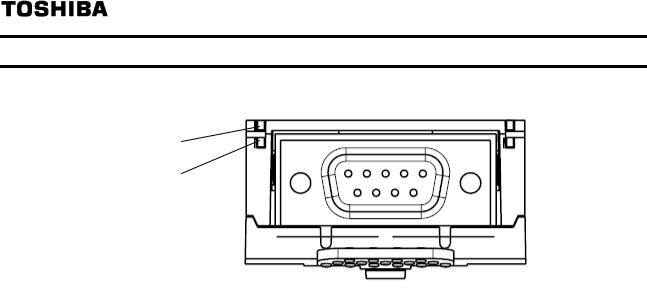
2.1. Exterior features
Status LED indicator (Refer to Section 2.2)
Release Tab
PROFIBUS connector (D-Sub 9pin)
To align VF-MB1/S15 side-by-side horizontally, "Vertical" type PROFIBUS connector is necessary.
- 6 -
E6581738
2.2. Status indicator
The PDP003Z has two LEDs, ST (status) and DX (data exchange) to indicate the statuses of PROFIBUS-DP and the PDP003Z itself.
ST (status)
DX (data Exchange)
ST (Status): Red LED
LED |
Meanings |
|
Off |
No diagnostics present |
|
|
8 Hz (Blinking 4 times/1sec.): |
|
|
Waiting for parameterization or configuration |
|
Flashes |
2 Hz (Blinking 1 times/1sec.): |
|
|
PDP003Z station address is "126". |
|
|
(Refer to 2.3 section .) |
|
Lights |
DP status error |
|
* For example, a station address is not setcorrectly. |
||
|
DX (Data exchange): Green LED.
Indicates the status of the PROFIBUS network.
It lights when the PDP003Z is on-line and data exchange is possible.
- 7 -

E6581738
2.3. VF-MB1/S15 Communication parameters
In a network, VF-MB1/S15 (PDP003Z) serves as a PROFIBUS slave device. PDP003Z configuration is set by the following parameters.
Parameter |
Function |
Adjustment range |
Default |
|
setting |
||||
|
|
|
||
c150 |
PDP003Z |
2 to 126 |
126 |
|
|
Station address |
The station address "126" cannot exchange data. |
|
|
c151 |
PDP003Z |
0: 12 Mbit/s |
- |
|
|
Baud rate Monitor |
1: 6 Mbit/s |
|
|
|
|
2: 3 Mbit/s |
|
|
|
|
3: 1.5 Mbit/s |
|
|
|
|
4: 500 kbit/s |
|
|
|
|
5: 187.5 kbit/s |
|
|
|
|
6: 93.75 kbit/s |
|
|
|
|
7: 19.2 kbit/s |
|
|
|
|
8: 9.6 kbit/s |
|
|
c152 |
PDP003Z |
0 Telegram 1 (PROFIdrive) |
- |
|
|
Profile Monitor |
1 Telegram 100 (Vender Spec. 1) |
|
|
|
|
2 Telegram 101 (Vender Spec. 2) |
|
|
|
|
3 Telegram 102 (Vender Spec. 3) |
|
|
c154 |
JOG1 Frequency |
0.0 to 20.0Hz |
5.0Hz |
|
|
(STW.8) |
|
|
|
c155 |
JOG2 Frequency |
0.0 to 20.0Hz |
5.0Hz |
|
|
(STW.9) |
|
|
|
c156 |
Tmax |
0.1 to 60.0s |
10.0s |
|
|
(ZSW.8) |
|
|
|
c157 |
Tolerance |
0.1 to 99.0% |
50.0% |
|
|
(ZSW.8) |
|
|
|
c100 |
Communication error |
0.0 to 100.0 sec |
0.0 |
|
|
detection delay time |
|
|
|
c101 |
Drive operation at the |
0: Stop and Communication release * |
4 |
|
|
communications |
(follows cmod and fmod setting) |
|
|
|
loss action |
1: None |
|
|
|
(Network wire breaks) |
2: Deceleration stop |
|
|
|
|
3: Coast stop |
|
|
|
|
4: Emergency stop |
|
|
|
|
5: Preset speed operation command |
|
|
|
|
(Operating at the preset speed operation frequency |
|
|
|
|
set with c102) |
|
|
c102 |
Preset speed |
0: None |
0 |
|
|
operation selection |
1 to 15: Preset speed (sr1 - sr7, f287 - f295) |
|
|
c103 ** |
Communication |
0: Disconnection detection |
1 |
|
|
time-out condition |
1: When communication mode enable (Both cmod |
|
|
|
selection |
and fmod are set CANopen or COM option) |
|
|
|
|
2: 1+Driving operation |
|
|
f899 |
Network option |
0: None |
0 |
|
|
reset setting |
1: Resetting the PDP003Z and the drive |
|
|
fd67 |
PDP003Z versioon |
PDP003Z firmware version |
- |
|
|
|
(ex. 0x1101 means "V1.01") |
|
*Do not set at VF-MB1 V1.00.
**It is necessary to enable "Watchdog" function with the configurator.
***When the parameters are changed or to reset err8, the power must be cycled (or set f899 to 1). After reset, the parameter changes become effective.
Set 1 to f899 by the PROFIBUS communication might not be able to be set.
****When fmod or cmod is set to “Communication option”, VF-MB1/S15 drives without Net Reference (STW Bit 13) or Net Control (STW Bit 12) at PROFIdrive.
Please note that drive keeps driving when the communication is lost if 1 (None) is set to Caution the parameter c101 (Drive operation at the communications loss action).
- 8 -
E6581738
3. Profile
3.1. Telegram
Telegram of PDP003Z is set up by the configurator.
The figures below show the Telegrams and configurations that the PDP003Z supports.
|
|
PKW |
|
|
PZD |
|
|
|
|
PZD1 |
PZD2 |
|
|
PKE |
IND |
PWE |
STW |
HSW PZD3 PZD4 PZD5 PZD6 |
|
|
|
|
|
ZSW |
HIW |
|
|
|
|
|
|
|
|
|
Telegram 1: PROFIdrive (PPO TYPE 3, 2PZD)
Telegram 100: Vendor Spec. (PPO TYPE 1, 4PKW / 2PZD)
Telegram 101: Vendor Spec. (PPO TYPE 2, 4PKW / 6PZD)
Telegram 102: Vendor Spec. (PPO TYPE 4, 6 ZD)
PKW: |
Parameter ID/value |
PZD: |
Process Data, cyclically transferred |
PKE: |
Parameter ID (1st and 2nd octet) |
IND: |
Sub-index (3rd octet), 4th octet is reserved |
PWE: |
Parameter value (5th until 8th octet) |
STW: |
Control word |
HSW: |
Main setpoint |
ZSW: |
Status word |
HIW: |
Main actual value |
*There are some by which a high byte / low byte is conversely treated depending on a master.
- 9 -

3.2. STW Control Word Data
PDP003Z supports only speed control mode.
Bit |
Value |
Name |
Note |
|
|
|
|
|
|
0 |
1 |
ON |
“Switched on” condition |
|
0 |
OFF |
Normal stop. |
||
|
||||
|
|
|
|
|
1 |
1 |
No Coast Stop |
All "Coast Stop (OFF2)" commands are withdrawn |
|
0 |
Coast Stop (OFF 2) |
Coast stop. |
||
|
||||
|
|
|
|
|
2 |
1 |
No Quick Stop |
All "Quick Stop (OFF3)" commands are withdrawn. |
|
0 |
Quick Stop (OFF 3) |
Quick Stop |
||
|
||||
|
|
|
|
|
3 |
1 |
Enable Operation |
The drive then runs-up to the setpoint. |
|
0 |
Disable Operation |
Normal stop. |
||
|
||||
|
|
|
|
|
4 |
1 |
Enable Ramp Generator |
- |
|
0 |
Reset Ramp Generator |
Output of the RFG is set to 0. |
||
|
||||
|
|
|
|
|
5 |
1 |
Unfreeze Ramp Generator |
- |
|
0 |
Freeze Ramp Generator |
Freeze the actual setpoint entered by the RFG *. |
||
|
||||
|
|
|
|
|
6 |
1 |
Enable Setpoint |
The value selected at the input of the RFG is switched-in. |
|
0 |
Disable Setpoint |
The value selected at the input of the RFG is set to 0. |
||
|
||||
|
|
|
|
|
7 |
1 |
Fault Acknowledge |
Fault reset (0 -> 1) |
|
0 |
No meaning |
- |
||
|
||||
|
|
|
|
|
8 |
1 |
JOG 1 ON ** |
VF-MB1/S15 drives with JOG 1 speed 1 (c154). |
|
0 |
JOG 1 OFF |
Jogging stop, if "JOG 1" was previously ON. Stop drive |
||
|
||||
|
according to VF-MB1/S15 setting parameter. |
|||
|
|
|
||
9 |
1 |
JOG 2 ON ** |
VF-MB1/S15 drives with JOG 2 speed 2 (c155). |
|
0 |
JOG 2 OFF |
Jogging stop, if "JOG 2" was previously ON. Stop |
||
|
||||
|
according to VF-MB1/S15 setting parameter. |
|||
|
|
|
||
10 |
1 |
Control By PLC |
The control word and main setpoint are activated. |
|
0 |
No Control By PLC |
The control word and main setpoint are inactivated. |
||
|
||||
|
|
|
|
|
11 |
--- |
Device-specification |
(Reserved.) |
|
|
|
|
|
|
12 |
1 |
Net Control |
PDP003Z control is enabled. |
|
|
|
|
||
|
0 |
Local Control |
PDP003Z control is disabled. |
|
|
|
|
|
|
13 |
1 |
Net Reference |
PDP003Z reference is enabled. |
|
0 |
Local Reference |
PDP003Z reference is disabled. |
||
|
||||
|
|
|
|
|
14 |
--- |
Device-specification |
(Reserved.) |
|
|
|
|
|
|
15 |
--- |
Device-specification |
(Reserved.) |
|
|
|
|
|
*RFG: Ramp Function Generator
**Operation is enabled, drive is in standstill and STW1 bit 4, 5, 6 = 0.
-10 -
Loading...