


6 F 3 B 0 3 6 4
DeviceNet Module DN211 for
PROSEC - T2/T2E/T2N
Instruction Manual
(Appendix3 DN211A)
REQUIREMENTS
∙Read this instruction manual carefully before operating.
∙Keep the manual aside to use when necessary.
∙Pack the manual with the DN211 when transferring or reselling.
January, 2001
© 2001 Toshiba Corporation
All rights reserved
UM-TS02***E16

6 F 3 B 0 3 6 4
© Copyright 1998 by Toshiba Corporation Tokyo, Japan
Toshiba Corporation reserves the right to make changes and improvements to this publication and/or related products at any time without notice. No obligation shall be incurred, except as noted in this publication.
This publication is copyrighted and contains proprietary material. No part of this book may be reproduced, stored in a retrieval system, or transmitted in any form or by any means — electrical, mechanical, by photocopying, recording, or otherwise — without obtaining prior written permission from Toshiba.
Important Information
Misuse of this equipment can result in property damage or human injury. Because controlled system applications vary widely, you should satisfy yourself as to the acceptabillity of this equipment for your intended purpose. In no event will Toshiba Corporation be responsible or liable for either indirect or consequential damage or injury that may result from the use of this equipment.
No patent liability is assumed by Toshiba Corporation with respect to the use of information, illustration, circuits equipment, of application examples in this publication.
¾ 1 ¾

6 F 3 B 0 3 6 4
Safety Precautions
Thank you for purchasing Toshiba's DeviceNet module (DN211) for programmable controllers PROSEC-T2 series (T2/T2E/T2N). This instruction manual describes the handling, precautions and operation of the DN211.
Be sure to carefully read this manual and all of other related documents to learn the safety precautions, notes, and knowledge about the DN211 before its installation, operation, or inspection. This will allow you to operate your DN211 comfortably.
Important Information
1. Toshiba's DN211 is designed and manufactured for use with general industrial equipment(manufacture line control devices, machine tools, etc.); it is not intended for use with equipment and systems which will endanger people's life during operation.
Contact the Toshiba dealer in advance when you are going to use your DN211 for special applications such as transport vehicles(train, etc.), medical equipment, aerospace equipment, nuclear power control equipment, underwater relay equipment, or other similar applications.
2.Toshiba's DN211 is manufactured under strict quality control. However, be sure to install safety systems to minimize the effect of a possible accident before you apply your DN211 to the equipment which will endanger people's life or cause serious damage on the surroundings if the DN211 should break down.
3.Toshiba's DN211 is meant for those who have general knowledge of handling control equipment, especially the knowledge about installation, wiring, operation, and maintenance of the DN211. Incorrect handling of the DN211 can cause electric shock, fire, failure, or/and malfunction. Therefore, don't engage in the installation, wiring, operation, or maintenance of the DN211 if your knowledge including electrical knowledge is not enough to handle control equipment. Instead, ask the qualified person to do such work.
4.This instruction manual and accompanying documents are meant for those who have general knowledge about the programmable controller and how to handle control equipment. If you have any questions on the content of this manual, don't hesitate to contact the Toshiba dealer.
¾ 2 ¾
6 F 3 B 0 3 6 4
Safety Precautions (continued)
[Warning indication]
This instruction manual has the following important indications and symbols to prevent bodily injury and property damage during operation. Be familiar with these safety indications to follow during operation. After reading the text, keep the manual aside to consult when necessary.
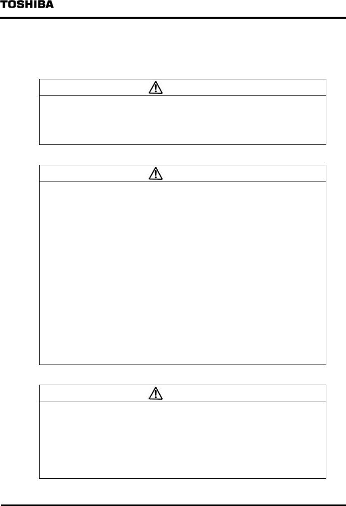
Description of Safety Signs
Indication |
Meaning |
|
|
DANGER |
Indicates misuse of the handling could cause a |
fatal accident or serious injury. |
|
|
|
CAUTION |
Indicates misuse of the handling could cause |
injury or material damage. |
|
|
|
Injury means a hurt, burn, or electric shock, which requires neither hospitalization nor long-term medical treatment by visits. Some of the CAUTION items, however, could bring about grave consequences depending on the situation. So be sure to always follow the CAUTION instructions.
¾ 3 ¾
6 F 3 B 0 3 6 4
Safety Precautions (continued)
∙ Precaution for operation
DANGER
1.Configure an emergency-stop circuit, interlock circuit, and/or other similar safety circuits outside the PC and DN211.
If the PC or DN211 gets failed or malfunctioned, it can cause an accident which will lead to bodily injury and/or mechanical damage.
T2/T2E/T2N User’s Manuals 3. Preparation for Operation (hardware)
CAUTION
2. Secure the safe environment before executing program modification, forcible output,
RUN, or HALT instruction during operation. An operational mistake can cause mechanical damage or accident.
T2/T2E/T2N User’s Manuals 3. Preparation for Operation (hardware)
∙ DIP switch for setting the operating mode/communication rate
CAUTION
1.Set and keep "OSEN" on the DIP switch to OFF. Setting it to ON can get failed or malfunctioned.
2.When you set "BUSOFF" on the DIP switch to OFF, transmission will restart automatically even when busoff occurs. Unless the cause of the DN211's busoff (cause of communication error) is solved, however, busoff may get repeated.
3.When you set both of communication rate DR0 and DR1 to ON and turn on the power of the T2/T2E/T2N, "Communication Rate Setting Failed" will appear with the following indications:
∙The "MS" LED is blinking red.
∙"F7" and the local station node address are being displayed alternately on the 7-segment LED.
To clear these indications, set DR0 and DR1 correctly and, issue a reset request or turn OFF and ON the power.
4.Set the communication rates of your nodes being connected to the network, to the same communication rate. Setting different communication rates on your different nodes will cause slave devices or the DN211 to get malfunctioned, resulting in no communication started.
Read the relevant manuals and descriptions to set the communication rate of your slave devices.
5.Don't change over the communication rates while your T2/T2E/T2N is rising just after the turning on power. In particular, never change the communication rate while communicating with slave devices. Failing to do so will cause "Communication Rate Setting Failed" to appear.
To clear this indication, set the DIP switch to the correct setting and, issue a reset request or turn OFF and ON the power.
3.2.1 DIP Switch for Setting the Operation Mode/Communication Rate
¾ 4 ¾
6 F 3 B 0 3 6 4
Safety Precautions (continued)
∙ Rotary switch for setting the node address
CAUTION
1.When you set a value within 64 to 99 to the node address of your DN211 and turn ON the power of your T2/T2E/T2N, "Node Address Setting Failed" will appear with the following indications:
∙The "MS" LED is blinking red.
∙"F6" and the local station node address are being displayed alternately on the 7-segment LED.
To clear these indications, set the correct value to the node address and, issue a reset request or turn OFF and ON the power.
2. If your DN211 node address has the same value with another node and when the DN211 comes into run state, "Node Address Duplicated" will appear with the following indications:
∙The "MS" LED is lighting red and/or the "NS" LED is lighting red.
∙"70" and the local station node address are being displayed alternately on the 7-segment LED.
To clear these indications, set the correct value to the node address and, issue a reset request or turn OFF and ON the power.
3.2.2 Rotary Switch for Node Address Setting
∙ Mounting in the base unit
CAUTION
1.Since the DN211 is designed for Toshiba's T2 series, be sure to mount your DN211 in the base unit, instead of using it in stand-alone; don't use it for other applications. Unauthorized applications can cause electric shock, bodily injury, and/or mechanical malfunction.
2.Be sure to turn OFF the power (on the T2 side and network side) before attaching or detaching the DN211 and/or the terminal block. Failing to do so will cause electric shock, malfunction, and/or failure.
3.Keep the DN211 free from foreign matter such as electric-wire waste. Failing to do so could cause fire, failure, and/or malfunction.
4.Check the connectors, cables, and base unit of the DN211, for their firm connection and mounting using stoppers and screws. Note loose connection or mounting can be shaky or easily disconnected off, resulting in failure or malfunction of the DN211.
3.3Mounting in the Base Unit
¾ 5 ¾

6 F 3 B 0 3 6 4
Safety Precautions (continued)
∙ Connection with the network
CAUTION
1.Don't engage in attaching or detaching the DeviceNet cable with the network side connector during network operation. Failing to do so can cause reverse connection or short circuit of the network power, resulting in no communication with other nodes.
2.When you connect the DeviceNet cable with the network side connector, be sure not to make the wrong connection. Failing to do so can cause short circuit of the network power, resulting in no communication with other nodes.
3.Neither attach nor detach the network side connector with the device side connector on the DN211 front panel while T2/T2E/T2N is rising just after the power is turned ON. Failing to do so can cause the DN211 to fail or malfunction.
4.Attaching the opposite end of the network side connector with/from the device side connector is not possible because of the specific form. Trying connecting the wrong end by excessive force can damage both the network side connector and the device side connector.
5.Be sure not to wire the cable in too tightly stretched state or in bent state. Also, don't put heavy stuff on the cable. Otherwise, the cable could break.
6.Ask the qualified expert for the installation work of the DeviceNet cables because it requires sufficient safety and noise-suppression measures. Refer to DeviceNet Volume I, Release 1.3, for the standard installation.
3.4Connection with the Network
¾ 6 ¾

6 F 3 B 0 3 6 4
Safety Precautions (continued)
∙ Turning ON/OFF the power of master/slave and the network
CAUTION
1.Be sure to turn ON the network power before turning ON the power of the DeviceNet devices.
Some nodes of the slave devices use the network power as the operation power while other slave devices indicate an error when their work power is not supplied. Therefore, be sure to switch ON the network power. Also note unless the network power is switched ON, your DN211 cannot start communication with slave devices.
2.Be sure the network power is supplied to all the nodes being connected with the network. The node to which no network power is supplied could cause communication obstacle to other nodes.
3.Make sure the power of all slave devices is switched ON before the DN211 begins communication. When the DN211 begins communication while the power of a slave device is not switched ON, the DN211 will display an error message of no response from that device.
4.While network communications are operating, don’t shut OFF the network power. Failing to do so will cause the entire network communications to stop and, one of the nodes become busoff state.
5.Switch OFF the T2/T2E/T2N side power at last after the DN211 begins communications. This helps the master device (DN211) to be recognized from the network and prevents slave devices from malfunctioning.
3.5The Network Power/Grounding
¾ 7 ¾
6 F 3 B 0 3 6 4
Safety Precautions (continued)
Relating to the following sections:
∙How to handle your DN211 (software)
∙Examples of DN211 applications
∙RAS information
CAUTION
1.Chapter 4 describes the subjects necessary for using diverse functions of the DN211 from the T2/T2E/T2N. Chapter 5 describes, based on the subjects explained in Chapter 4, setting the DN211 parameters, activating transmission, inputting/outputting data with slave devices, and the procedure for reading RAS information including event history, and sample programs.
Write programs after understanding the contents. As sample programs are basic, you need to examine your programs from beginning to end before applying them to actual systems.
4.How to Handle Your DN211 (software)
5.Examples of DN211 Applications
6.RAS Information (except RAS area on communication memory)
∙Allocation of slave device data to input/output data area
CAUTION
1.When a slave device has odd transmission/reception bytes in size, the actual size plus 1 byte are allocated to the DN211 input/output area.
2.When you add a new slave device, enter a new value larger than the node addresses of the present slave devices. For Figure 4.8, enter a value larger than "41" for the node address of a new slave. If the node address of a new slave device is set to "18", allocating data area of node addresses 20/30/40 will be shifted.
3.Don't change the input/output data size for slave devices (FLEX-I/O, etc.) which are flexible in data allocation size. If changed, the slave devices with a node address larger than that of the slave device changed data size will be shifted in their data allocation.
4.4Allocating Slave Device Data to the Input/Output Data Area
∙Operating mode of the T2/T2E/T2N and the DN211
CAUTION
1.If the T2/T2E/T2N turns into HALT/ERROR mode, the DN211 in run mode becomes standby mode.
4.6.1DN211 Operation Mode
5. Examples of DN211 Applications
¾ 8 ¾
6 F 3 B 0 3 6 4
Safety Precautions (continued)
∙ Action when your DN211 is reset
CAUTION
1.Neither issue a request from the T2/T2E/T2N to DN211 while the DN211 is being reset nor execute data input/output. Otherwise, the instruction requested will be completed abnormal (error of station mode abnormal), or the module self-check will fail turning into down mode.
[4.6.2 Reset Request]
∙ Setting slave device parameters
CAUTION
1.The parameter setting request (slave device) sets the parameters of slave devices on to the non-volatile memory in the DN211. As long as the slave devices configuration is unchanged, you don’t need to execute this request every time when the power is switched ON. In addition, when the parameters of the slave device requested and the parameters of the slave device in the non-volatile memory are same, this setting request is not executed.
2.When the slave devices configuration needs to be changed, delete the salve devices parameters using a reset request before setting new slave devices parameters.
3.The number of times available for setting slave devices parameters in the nonvolatile memory of the DN211 is 300 times.
4.The DN211 has the following restriction for transmitting "0 byte" to a slave device from the DN211.
∙When a slave device comes into no communication state with the DN211 due to some reason (for example, the power of the slave device is OFF; the connector is disconnected, etc.), the DN211 cannot recognize the slave device is abnormal.
Even after the cause of the failed communications is solved, the DN211 and the slave device cannot communicate with each other.
Note: The above restriction of the present DN211 will be solved by a version-up of the internal software.
4.6.4 Parameter Setting Request (slave device)
∙ Installation environment and mounting in the base unit
CAUTION
1.Apply the environment specified in the User’s Manual of the T2/T2E/T2N.
When using your DN211 in the environment other than specified, the DN211 can cause electric shock, fire, failure, and/or malfunction.
2.Mount your DN211 in the way specified in the User’s Manual of the T2/T2E/T2N.
If mounted in the direction other than specified or if mounted incorrectly, the DN211 could fall off, or cause fire, failure, and/or malfunction.
8.1Installation Environment and Mounting in the Base Unit
¾9 ¾
6 F 3 B 0 3 6 4
Safety Precautions (continued)
∙ Mounting/removing the module
CAUTION
1.Since the DN211 is designed for the T2 series, be sure to attach it to the base unit. Don't use your DN211 in stand-alone state or to other applications.
Failing to do so could cause electric shock, injury, and/or failure.
2.Be sure to turn OFF the power before mounting, removing, wiring, or un-wiring the DN211. Failing to do so can cause electric shock, malfunction, and/or failure.
3.Keep your DN211 free from foreign matter such as electric-wire waste. Failing to do so could cause fire, failure, and/or malfunction.
4.Check the connectors and cables and the DN211 mount in the base unit, for their firm connections and mount using stoppers/screws. Loose connection and mounting becomes shaky and disconnected, resulting in failure or malfunction.
8.2Mounting/Removing the Module
∙Wiring the power and grounding
CAUTION
1.Be sure to turn OFF the power before wiring cables. Failing to do so could cause electric shock.
2.Use crimp-on connectors with sheath or cover the conducting part with tape when wiring your T2/T2E/T2N power module. Also, handle the terminal block cover correctly to avoid fall-off and damage when fixing. Be sure to fix the cover on the terminal block when completing the wiring. If the conducting part is exposed, you can have electric shock.
3.Be sure to have grounding. When not grounded, electric shock and/or malfunction can occur.
4.Make sure the wiring is correct when connecting the DeviceNet cables to the network side connector. The short circuit of the network power, etc. can fail communication with other nodes.
5.When you are going to detach or connect the network side connector to/from the device side connector on the DN211 front panel, don't engage yourself while the T2/T2E/T2N side power is rising. Failing to do so can cause the DN211 to fail or malfunction.
6.Attaching the opposite end of the network side connector with/from the device side connector is not possible because of the specific form. Trying connecting the wrong end by excessive force can damage both the network side connector and the device side connector.
7.Ask a qualified person to wire cables. Incorrect wiring can cause fire, failure, and/or electric shock.
8.3Power Unit Wiring/Grounding
¾ 10 ¾
6 F 3 B 0 3 6 4
Safety Precautions (continued)
∙ Basic caution in network Installation
CAUTION
1.Ask the qualified subcontractor for sufficient safety and noise-suppression measures when installing the DeviceNet cable.
Refer to DeviceNet Volume I, Release1.3, for the standard installation.
2.It is recommended to consign a subcontractor specialized in safety measures and standards.
3.Avoid the network components of the DeviceNet cable from being installed in a noisy environment. When installing, be sure to furnish noise-suppression measures as described in the following section.
8.4Network Installation
∙Maintenance
CAUTION
1.Be sure to turn OFF the power mounting or removing the module, terminal block, and cable. Failing to do so can cause electric shock, malfunction, and/or failure.
2.Carry out daily check, periodical check, and cleaning to keep the system in normal condition.
3.If your DN211 does not operate normally, refer to "7. Troubleshooting" to identify the cause of the trouble.
Contact a Toshiba's branch office (or dealer) or service agency for returning your DN211 for repair when failed. Operation and safety of your DN211 can be guaranteed only when repaired by Toshiba or a Toshiba's authorized service agency.
4.Neither try to disassemble nor modify the hardware of the module. Similarly, don't modify the software by any means. Failing to do so could cause fire, electric shock, and/or injury due to failure or malfunctioning.
5.Make sure you are safe when measuring the voltage on the connector of the module. Failing to do so could cause electric shock.
6.Stop the network and turn OFF the T2/T2E/T2N side power before replacing the module.
Failing to do so could cause electric shock, malfunction, and/or failure.
7.Don't use your DN211 in abnormal condition such as smoking or nasty smelling. Failing to do so could cause fire, electric shock, and/or failure.
If such an abnormal condition happens, turn OFF all the power supplies immediately and contact a Toshiba branch office (or dealer) or authorized service agency.
Since it is very dangerous, don't engage yourself in modifying or repairing your
DN211 by any means.
Appendix (maintenance)
¾ 11 ¾

6 F 3 B 0 3 6 4
Usage Recommendations
This section puts together the knowledge and handling manners necessary for correct operation. Read the section carefully and be familiar with equipment knowledge, safety information, and notes.
∙ Network cnfiguration
Usage Recommendation
1.Don't make a network configuration whose extended trunk line and drop lines have no node being connected.
2.Don't attach a terminal resistor to the node. It could cause communication error.
3.Attach a terminal resistor to both ends of the trunk line; don't attach a terminal resistor on the end of a drop line. Attach only to both ends of the trunk line.
1.2Network Configuration of the DeviceNet
∙Switch setting
Usage Recommendation
1.Use a small minus screwdriver for changing the value of the DIP switch.
3.2.1DIP Switch for Setting the Operation Mode/Communication Rate
Usage Recommendation
1.Use a small minus screwdriver for changing values of the rotary switch.
3.2.2Rotary Switch for Node Address Setting
∙Connecting your DN211 with the network side connector
Usage Recommendation
1.Loosen the cable fixing screws on the connector before inserting a cable into the network side connector. The cable cannot be fixed when the screws are kept tightened.
2.Colors corresponding to cable colors are printed by the device side connector of the DN211. Match the cable colors with the printed colors to have correct wiring.
3.The DN211 and the DN311 (DeviceNet module for T3/T3H) have different directions for attaching the network side connector.
4.DeviceNet cable, power tap, and device tap (connecting the trunk line with drop lines) are necessary when constructing a system using a DeviceNet. Refer to "3.6 The Network Components" for detail.
Some of the network components must be prepared by the user.
5.When you use the network side connector that has the upper and lower rows with holes for cables (at the left-side Figure 3.5), the connector protrudes from the leftside DN211 about 5mm. When you attach or detach the left-side module of DN211, you must detach the connector from DN211.
3.4.2Connecting Network Side Connector to the DN211
¾12 ¾

6 F 3 B 0 3 6 4
Usage Recommendations (continued)
∙ Network power configuration
Usage Recommendation
1.Consider not only current capacity of the trunk line but also current capacity of drop lines when you install a node on a drop line.
2.In particular, when you are connecting nodes in daisy chain on a drop line, be careful not to have insufficient current capacity.
3.Use a network power whose capacity is much larger than the total current consumption necessary for the network.
3.5.2How to Configure Network Power Units
∙Network power unit
Usage Recommendation
1.Use a network power whose capacity is much larger than the total current consumption necessary for the network.
3.5.3The Network Power Unit(24Vdc)
∙Registering your DN211 module
Usage Recommendation
1.When your DN211 is going to be I/O registered in the T2/T2E/T2N, leave blank for the slot where the DN211 is installed.
After automatic allocation is performed, the DN211-installed slot is left blank.
4.How to Handle Your DN211 (software)
∙Node address of your DN211
Usage Recommendation
1.Set the node address of your DN211 to a value smaller than the node addresses of slave devices(because of the feature of CAN currently used in the DeviceNet).
4.6.3Parameter Setting Request (local node)
∙How to solve overrun errors
Usage Recommendation
1.Reduce the network communication speed when an overrun error occurs (500 kbps -> 250 kbps -> 125 kbps).
7.Troubleshooting (Data Communication with Slave Devices)
¾ 13 ¾

6 F 3 B 0 3 6 4
About This Manual
Thank you for purchasing Toshiba's programmable controller PROSEC-T2 series (T2/T2E/T2N).
This manual describes the specification, handing manners, and sample programs of the DeviceNet module (called as the "DN211") used for PROSEC-T2 series. Read this manual to handle and operate your DN211 correctly.
This manual consists of the following chapters:
Chapter 1: Overview of the DeviceNet Module
Outlines functions of the DN211, specification, and application systems, etc. Read this chapter to know basic performances of the DN211.
Chapter 2: Names and Functions of DN211 Parts
Describes the names and functions of DN211 parts. Read this chapter carefully since important information, required for hardware settings in the next chapter, is included in this chapter.
Chapter 3: Preparation for Operation (hardware)
Describes the hardware preparation and setting necessary for your DN211 operation.
Chapter 4: How to Handle Your DN211 (software)
Explains accessing the DN211 from the T2/T2E/T2N and software settings.
Chapter 5: Examples of DN211 Applications
Describes sample programs of handling the DN/211 explained in Chapter 4.
Chapter 6: RAS Information (except RAS area on communication memory)
Describes the formats and contents of RAS information on the DN211 (except for RAS area on communication memory).
Chapter 7: Troubleshooting
Explains possible causes and solutions when your DN211 malfunctions.
Chapter 8: Installation/Wiring Work
Explains how to install your DN211 and T2/T2E/T2N, how to wire transmission cables, and how to arrange other preparation work.
Appendix
Describes the maintenance and check items and the execution time of READ/WRITE instructions of the T2/T2E/T2N.
¾ 14 ¾

6 F 3 B 0 3 6 4
In addition to this instruction manual, the following descriptions about the T2/T2E/T2N, instruction words, programmer, and computer link procedure transmission are also prepared for your reading.
∙T2 User’s Manual Basic Hardware and Function (UM-TS02***-E001) Describes hardware (basic unit, basic I/O) and the main unit functions of the T2.
∙T2E User’s Manual Basic Hardware and Function (UM-TS02E**-E001) Describes hardware (basic unit, basic I/O) and the main unit function of the T2E.
∙T2E User’s Manual Enhanced Communication Function(UM-TS02E**-E003) Describes the functions and how to handle the optional communication card for the T2E.
∙T2N User’s Manual Basic Hardware and Function (UM-TS02N**-E001) Describes hardware (basic unit, basic I/O) and the main unit functions of the T2E.
∙Instruction Manual TOSLINE-S20LP T2N/T3H Stations (6F3B0356)
Describes the system configuration of the T2N built-in data link system "TOSLINE-S20LP" and its device configuration, and the functions, performances, and handling of "TOSLINES20LP."
∙Built-in Ethernet Module for T2N (PU235N/245N) Instruction Manual (6F3B0362) Describes the Ethernet built-in T2N and the handling.
∙T-Series Instruction Set (UM-TS03***-E004)
Explains a detailed specification of instruction words about the ladder diagram and SFC programming languages, which are supported by Toshiba's T-series.
∙T-Series Computer Link Operation Manual (UM-TS03***-E008)
Describes the specification and operating manners for the computer link function built in Toshiba's T-series CPU.
Registered Trademarks:
nDeviceNet is a registered trademark of ODVA (Open DeviceNet Vendor Association).
nPowerTap, T-Port Tap, DeviceBox Tap, and FLEX I/0 are registered trademarks of RockWell Automation Co., Ltd.
nCOMBICON is a registered trademark of Phoenix Contact Corporation.
¾ 15 ¾

6 F 3 B 0 3 6 4
Contents |
|
|
1. Overview of The DeviceNet Module .................................................................. |
19 |
|
1.1 |
Features and System Configuration Examples of the DeviceNet Module (DN211)19 |
|
1.2 |
Network Configuration of DeviceNet .................................................................. |
21 |
|
1.2.1 The Network Configuration ....................................................................... |
21 |
|
1.2.2 Trunk Line/Drop Line and Maximum Cable Length................................... |
22 |
|
1.2.3 The Terminal Resistor .............................................................................. |
24 |
1.3 |
Conformity Specification and Trademarks......................................................... |
25 |
1.4 |
The Basic Functions........................................................................................... |
26 |
|
1.4.1 The Polling Instruction/Response Mode ................................................... |
26 |
|
1.4.2 The Bit Strobe Instruction/Response Mode .............................................. |
27 |
|
1.4.3 Synchronization/Asynchronous Mode and Data Update Cycle ................. |
28 |
1.5 |
The DN211 Specification .................................................................................... |
30 |
|
1.5.1 The Function Specification ....................................................................... |
30 |
|
1.5.2 Number of Mounting Modules ................................................................... |
31 |
2. Names and Functions of DN211 Parts ............................................................. |
33 |
|
2.1 |
Outer Dimensions and Sizes.............................................................................. |
33 |
2.2 |
Names of DN211 Parts ........................................................................................ |
34 |
2.3 Functions of DN211 Parts.................................................................................... |
36 |
|
3. Preparation for Operation (hardware)............................................................... |
38 |
|
3.1 |
DN211 Setting Flowchart (hardware).................................................................. |
38 |
3.2 |
Switch Setting.................................................................................................... |
39 |
|
3.2.1 DIP Switch for Setting the Operation Mode/Communication Rate ............. |
39 |
|
3.2.2 Rotary Switch for Node Address Setting ................................................... |
41 |
3.3 |
Mounting in the Base Unit.................................................................................. |
42 |
3.4 |
Connection with the Network ............................................................................. |
43 |
|
3.4.1 Connecting DeviceNet Cables to Network Side Connectors ..................... |
44 |
|
3.4.2 Connecting the Network Side Connector to the DN211 ............................ |
45 |
3.5 |
The Network Power/Grounding.......................................................................... |
47 |
|
3.5.1 The Network Power Mechanism................................................................ |
47 |
|
3.5.2 How to Configure Network Power Units ..................................................... |
48 |
|
3.5.3 The Network Power Unit (24 Vdc) ............................................................. |
54 |
|
3.5.4 The Network Grounding ........................................................................... |
55 |
|
3.5.5 Procedure for Switching-ON/Shutting-OFF the Power .............................. |
56 |
3.6 |
The Network Components................................................................................. |
57 |
4. How to Handle Your DN211 (software)............................................................. |
60 |
|
4.1 |
Configuration of the DN211 Communication Memory......................................... |
61 |
4.2 |
The Input/Output Data Area................................................................................ |
62 |
4.3 |
The RAS Information Area ................................................................................. |
66 |
¾ 16 ¾

|
|
6 F 3 B 0 3 6 4 |
4.4 |
Allocating Slave Device Data to the Input/Output Data Area.............................. |
75 |
4.5 The Semaphore Area......................................................................................... |
76 |
|
4.6 Requests to the DN211........................................................................................ |
79 |
|
|
4.6.1 The DN211 Operation Modes................................................................... |
80 |
|
4.6.2 Reset Request ......................................................................................... |
81 |
|
4.6.3 Parameter Setting Request (local node) .................................................. |
82 |
|
4.6.4 Parameter Setting Request (slave device) ............................................... |
85 |
|
4.6.5 Operation Mode Control Request............................................................. |
88 |
|
4.6.6 RAS Information Read Request................................................................ |
89 |
|
4.6.7 Time Setting Request ............................................................................... |
90 |
4.7 |
Completion Status.............................................................................................. |
91 |
5. Example of DN211 Applications......................................................................... |
92 |
|
5.1 |
The DN211 Operation Order ............................................................................... |
92 |
5.2 |
Module Setting Procedure ................................................................................. |
93 |
|
5.2.1 Accessing the DN211 in Module Setting ................................................... |
94 |
|
5.2.2 Configuration of a Module Setting Sample Program................................. |
96 |
|
5.2.3 Reset Request ......................................................................................... |
97 |
|
5.2.4 Parameter Setting Request (local node) .................................................. |
99 |
|
5.2.5 Parameter Setting Request (slave device) ............................................. |
100 |
|
5.2.6 Operation Mode Control Request........................................................... |
106 |
|
5.2.7 RAS Information Read ............................................................................ |
111 |
|
5.2.8 Time Setting Request ............................................................................. |
114 |
5.3 |
Slave Data Input/Output ................................................................................... |
116 |
|
5.3.1 Slave Device Check ............................................................................... |
116 |
|
5.3.2 Asynchronous Mode Data Input/Output.................................................. |
117 |
|
5.3.3 Synchronous Mode Data Input/Output ................................................... |
122 |
6. RAS Information (except RAS area on communication memory) |
.......... 129 |
|
6.1 Module Status / Network Status LED (MS/NS)................................................... |
130 |
|
6.2 |
Indications of the 7-Segment LED.................................................................... |
131 |
6.3 |
RAS Information Reading Data ........................................................................ |
133 |
|
6.3.1 The RAS Counter ................................................................................... |
133 |
|
6.3.2 Event History .......................................................................................... |
136 |
|
6.3.3 Execution Node Information .................................................................... |
139 |
7. Troubleshooting.................................................................................................. |
141 |
|
7.1 When Starting up the Module .......................................................................... |
141 |
|
7.2 |
Reset Request (scan list clear).......................................................................... |
142 |
7.3 |
When the Module Doesn't Become Run Mode ................................................. |
143 |
7.4 Data Communication with Slave Devices......................................................... |
146 |
|
¾ 17 ¾

6 F 3 B 0 3 6 4
8. Installation/Wiring Work..................................................................................... |
148 |
|
8.1 |
Installation Environment and Mounting in the Base Unit.................................. |
148 |
8.2 |
Mounting/Removing the Module ...................................................................... |
148 |
8.3 |
Power Unit Wiring/Grounding .......................................................................... |
149 |
|
8.3.1 Power Unit Wiring ................................................................................... |
149 |
|
8.3.2 Grounding .............................................................................................. |
149 |
8.4 |
Network Installation ......................................................................................... |
150 |
|
8.4.1 Installation Gists Outside the Board ....................................................... |
150 |
|
8.4.2 Installation Gists Inside the Board .......................................................... |
153 |
Appendix |
|
|
|
Appendix 1 Maintenance and Inspection...................................................... |
154 |
|
Appendix 2 READ/WRITE Instruction Execution Time .................................. |
156 |
|
Appendix 3 DN211A ..……….………………………………………………………... 157 |
|
¾ 18 ¾

6 F 3 B 0 3 6 4
1. Overview of the DeviceNet Module
1.1Features and System Configuration Examples of the DeviceNet Module (DN211)
This section describes the features and system configuration examples of the DeviceNet module (DN211) for the programmable controller PROSEC-T2 series (T2/T2E/T2N). The DN211 is an interface module for connecting the DeviceNet, which is a device level network for FA, to the PROSEC-T2 series.
Hereafter, the programmable controllers PROSEC T2, PROSEC-T2E, and PROSEC-T2N are respectively called the "T2", "T2E", and "T2N". Likewise, the DeviceNet module for the T2 series is also called the "DN211."
(1)Conformed with DeviceNet
DeviceNet is a standardized device level network for factory automation(FA), developed by RockWell Automation Co. in USA. A nonprofit organization, called ODVA (Open DeviceNet Vendor Association), is serving as the center for the maintenance/extension of the DeviceNet specification and for conformable products introduction.
The DN211, functioning as the master (parent station) device on a DeviceNet, performs data input/output between the master device and the DeviceNet slave (child station) devices, which are developed by different makers (vendors) in and outside Japan and conform with the DeviceNet, to interface such slave devices with the T2/T2E/T2N .
(2)Input/Output Data Size, Number of Slave Devices, communication Rate and Network Length
A DN211 allows a DeviceNet to have one network to be connected. The sizes of inputting and outputting data, allowed between a DN211 and slave devices are 128 words for input and 128 words for output (one word = 16 points).
Input data and output data, so far as each of them is within 128 words in total, can be exchanged data with up to 63 slave devices. (Since the amount of data outputted to a slave device and the amount of data inputted from a slave device vary depending on the slave device, check the slave device specification of data size).
The definition of input data and output data, dealt in this book, is shown in the following figures.
Output data : |
T2/T2E/T2N |
→ |
DN211 |
→ |
Slave device |
|
|
|
|
|
|
|
|
|
|
|
|
Input data : |
T2/T2E/T2N |
← |
DN211 |
← |
Slave device |
|
|
|
|
|
|
Figure 1.1 Definition of Output Data and Input Data
Three types of communication rates, namely 500 kbps, 250 kbps and 125 kbps are available. The maximum network length varies depending on the communication rate (l00 m for 500 kbps, 250 m for 250 kbps, and 500 m for 125 kbps).
The detail is explained in "1.2 Network Configuration of DeviceNet."
¾ 19 ¾
6 F 3 B 0 3 6 4
(3) Means of Inputting/Outputting Data
The DN211 supports "polling instruction/response" and "bit strobe instruction/response," both of which are specified in the DeviceNet specification as the means of inputting/outputting data to/from slave devices. The details of "polling instruction/response" and " bit strobe instruction/response" are explained in "1.4 The Basic Functions."
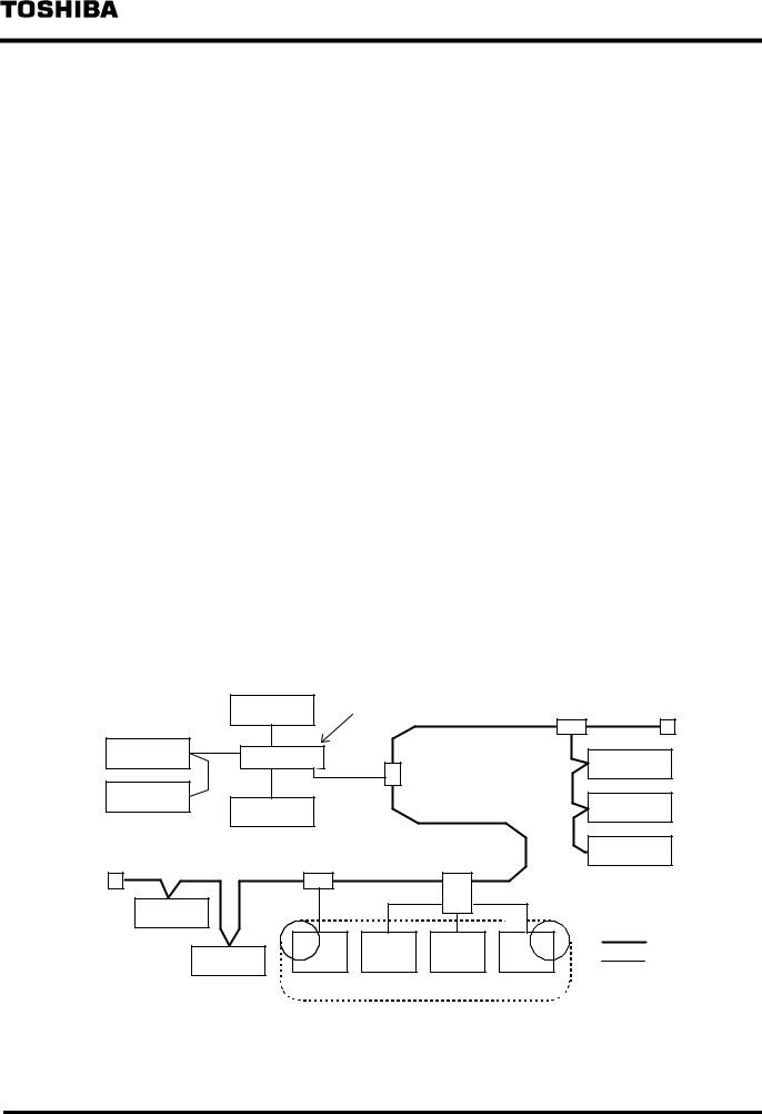
(4) Examples of the System Configuration
This section describes a typical system configuration using the DN211, which is mounted on the I/O slot of the T2/T2E/T2N. The DN211 allows the T2/T2E/T2N to exchange data with slave devices on the DeviceNet.
In the following example, the DN211 is connected with slave devices, such as input/output devices, sensor, and drive unit, which conforms with the DeviceNet specification. Moreover, a Toshiba's original control LAN (TOSLINE-S20) is used to connect the T2/T2E/T2N with a higher-rank controller.
A number of wiring combinations meeting the installation environment are available because the T branch topology and the multi-drop topology are combinable when wiring a DeviceNet.
High-rank computer
T2N: PROSEC − T2N
T2E: PROSEC − T2E
S20: TOSLINE − S20
|
|
|
|
|
|
|
|
|
|
|
|
|
|
|
|
|
|
|
|
|
|
|
|
|
|
|
|
Ethernet |
|
||||||
|
|
|
|
|
|
|
|
|
|
|
|
|
|
|
|
|
|
|
|
|
|
|
|
|
|
|
|
||||||||
|
|
|
|
|
|
|
|
|
|
|
|
|
|
|
|
|
|
|
|
|
|
|
|
|
|
|
|
||||||||
|
|
|
|
|
|
|
|
|
|
|
|
|
|
|
|
|
|
|
|
|
|
|
|
|
|
|
|
|
|
TOSLINE S20 |
|
||||
|
|
|
|
|
|
|
|
|
|
|
|
|
|
|
|
|
|
|
|
|
|
|
|
|
|
|
|
|
|
||||||
|
|
|
|
|
|
|
|
|
|
|
|
|
|
|
|
|
|
|
|
|
|
|
|
|
|
|
|
|
|
|
|
|
|
|
|
|
|
T |
S |
|
|
|
|
|
|
|
T |
|
|
|
|
D |
|
D |
|
|
|
|
|
|
|
|
|
|
|
||||||
|
|
2 |
2 |
|
|
|
|
|
2 |
|
|
|
|
N |
|
N |
|
|
|
|
|
|
|
|
|
|
|
||||||||
|
|
E |
0 |
|
|
|
|
|
|
|
N |
|
2 |
|
2 |
|
|
|
|
|
|
|
|
|
|
|
|
|
|||||||
|
|
|
|
|
|
|
|
|
|
|
|
|
|
|
1 |
|
1 |
|
|
|
|
|
|
|
|
|
|
|
|
|
|||||
|
|
|
|
|
|
|
|
|
|
|
|
|
|
|
1 |
|
1 |
|
|
|
|
|
|
|
|
|
|
|
|
|
|||||
|
|
|
|
|
|
|
|
|
|
|
|
|
|
|
|
|
|
|
|
|
|
|
|
|
DeviceNet |
|
|||||||||
|
|
|
|
|
|
|
|
|
|
|
|
|
|
|
|
|
|
|
|
|
|
|
|
|
|
||||||||||
|
|
|
|
|
|
|
DeviceNet |
|
|
|
|
|
|
|
|
|
|
|
|
|
|
|
|
|
|
|
|
|
|
||||||
|
|
|
|
|
|
|
|
|
|
|
|
|
|
|
|
|
|
|
|
|
|
|
|
|
|
|
|
|
|
|
|
|
|
|
|
|
|
|
|
|
|
|
|
|
|
|
|
|
|
|
|
|
|
|
|
|
|
|
|
|
|
|
|
|
|
|
|
|
|
|
|
|
|
|
|
|
|
|
|
|
|
|
|
|
|
|
|
|
|
|
|
|
|
|
|
|
|
|
|
|
|
|
|
|
|
|
|
|
|
|
|
|
|
|
|
|
|
|
|
|
|
|
|
|
|
|
|
|
|
|
|
|
|
|
|
|
|
|
|
|
|
|
|
|
|
|
|
|
|
|
|
|
|
|
|
|
|
|
|
|
|
|
|
|
|
|
|
|
|
|
|
|
|
|
|
|
|
|
|
|
|
|
|
|
|
|
|
|
|
|
|
|
|
|
|
|
|
Input/Output |
|
|
|
|
|
Input/Output |
|
|
|
|
|
|
|
|
|
|
|
|
|
|
device |
|
|
|
Input/Output |
||||
|
|
|
|
|
|
|
|
|
|
||||||||||||||
|
|
|
|
|
|
|
|
|
|
|
|
|
|
|
|
|
|
device |
|||||
device |
|
|
|
|
|
|
|
|
|
|
|
|
|
|
Sensor |
|
|
||||||
|
Sensor |
|
|
|
|
|
|
|
|
||||||||||||||
|
|
|
|
|
|
|
|
|
|
|
|
|
|||||||||||
|
|
|
|
|
|
|
|
|
|
|
|
|
|
|
|||||||||
|
|
|
|
|
|
|
|
|
|
|
|
|
|
|
|
|
|
|
|
|
|
|
|
|
|
|
|
|
|
|
|
|
|
|
|
|
|
|
|
|
|
|
|
|
|
|
|
|
|
|
|
|
|
|
|
|
|
|
Drive unit |
|
Drive unit |
|
|
|
|
||||||
|
|
|
|
|
|
|
|
|
|
|
|
|
|
|
|
||||||||
|
|
|
|
|
|
|
|
|
|
|
|
|
|
|
|
|
|
|
|
|
|||
Input/Output device |
|
|
|
|
Sensor |
|
|
|
|
||||||||||||||
|
|
|
|
|
|
|
|
|
|
|
|
|
|
|
|
|
|
|
|
|
|
||
|
|
|
|
|
|
|
|
|
|
|
|
|
|
|
|
|
|
|
|
|
|
|
|
Figure 1.2 Example of the System Configuration
¾ 20 ¾
6 F 3 B 0 3 6 4
1.2 Network Configuration of DeviceNet
This section describes the network configuration of the DeviceNet.
1.2.1The Network Configuration
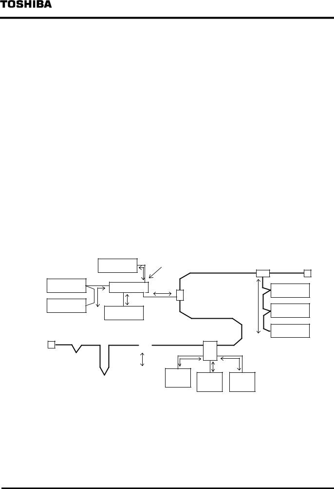
The network configuration of a DeviceNet consists of a trunk line and drop lines as shown in Figure 1.3.
(1)The Nodes
The nodes of the DeviceNet in Figure 1.3 have slave devices such as input/output devices, sensors, and drive units, and a master device such as the DN211, to exchange data with each other. One network can have up to 64 nodes and one master device. Physical arrangement of a master device and slave devices has no particular restrictions.
Each of the DeviceNet devices on a network has a unique number (NA: node address) to identify the node from the other nodes. The node address values must be within 0 to 63 in decimal scale, and the node addresses in the network must be different from the others.
(2)The Trunk Line
According to the DeviceNet specification, a trunk line is a cable which connects nodes located most distant. The trunk line can have nodes directly-connected with it (connection with no drop line). The length of the trunk line varies depending on the communication rate of the network. The both ends of the trunk line need a terminal resistor.
(3)The Drop Line
All the cables branched from taps on the trunk line fall on drop lines. The drop line has a maximum length of 6 meters (from tap to most distant node) regardless of the communication rate on the network (The total extension of drop lines varies depending on the communication rate on the network). A drop line can have one or more nodes connected. The following three types of node configurations are available, as shown in Figure 1.3.
a)Configuration of drop lines short from the tap/multiport tap
b)Configuration of multidrops on a drop line
c)Configuration of branches on a drop line (no branch configuration for the trunk line)
Branch configuration |
Node 45 |
Multiport tap |
|
Tap |
Terminal |
||
|
|
|
resistor |
||||
Node 35 |
|
|
|
|
|
|
Node 50 |
|
|
|
|
|
Tap |
|
|
|
|
|
|
|
|
|
|
Node 30 |
|
|
|
|
|
|
Node 55 |
|
|
Node 40 |
|
|
|
|
|
|
|
|
|
|
|
|
|
Terminal |
|
|
Tap |
|
Multiport tap |
|
Node 60 |
|
|
|
|
|
|||
resistor |
|
|
|
|
Multidrop |
||
|
|
|
|
|
|
||
|
|
|
|
|
|
|
|
|
|
|
|
|
|
|
configuration |
Node 0 |
|
|
|
|
|
|
|
|
|
|
Node |
Node |
Node |
Node |
Trunk line |
No drop line |
Node 5 |
10 |
15 |
20 |
25 |
Drop line |
|
Short drop line configuration
Figure 1.3 Example of DeviceNet Network Configuration
¾ 21 ¾
6 F 3 B 0 3 6 4
1.2.2Trunk Line/Drop Line and Maximum Cable Length
The DeviceNet specification stipulates the Thick Cable and the Thin Cable. For detail, see DeviceNet Volume I. Currently, cables conforming with the standards of the Thick Cable and Thin Cable are available in the commercial market. Buy ones which meet the configuration of your network (Details are explained in "3.6 The Network Components").
(1)The Trunk Line
The trunk line of a DeviceNet consists of a Thick Cable or a Thin Cable (their mixture is also possible). Since the Thin Cable is flexible compared with the Thick Cable, wiring the cable is easy. Conversely, the Thick Cable allows longer network cabling than the Thin Cable. A maximum of the trunk line length varies depending on the type of cable used and the communication rate on the network. For details, see "3 The Maximum Network Length."
(2)The Drop Line
The drop lines of a DeviceNet consists of Thin Cables. Table 1.1 lists the length of drop lines and the total length. A node on a drop line can be configured in a short drop line configuration/multidrops configuration/short brunch configuration. Figure 1.4 shows how to calculate the drop line length and the total length by different configurations.
Table 1.1 Maximum Drop Line Length
Communication |
Drop Line |
Total Extension by Network |
|
Rate |
|||
|
|
||
|
|
|
|
|
|
|
|
125 kbps |
|
156 meters |
|
250 kbps |
6 meters |
78 meters |
|
500 kbps |
|
39 meters |
|
|
|
|
Branch configuration |
Node 45 |
Multiport tap |
Tap |
Terminal |
|
resistor |
|||
|
|
g |
|
|
Node 35 |
Node 50 |
|
f |
||
i |
Tap |
|
h |
e |
|
Node 30 |
||
Node 55 |
||
Node 40 |
Terminal |
|
|
Tap |
|||||
resistor |
|
|
||||||
|
|
|
|
|
|
|
|
|
|
|
|
|
|
a |
|
|
|
|
Node 0 |
|
|
|
||||
|
|
|
|
|
|
|
|
|
|
|
|
|
|
|
|
|
|
|
|
|
|
|
|
Node |
||
|
|
|
|
|||||
|
|
|
Node 5 |
|
10 |
|
||
|
|
|
|
|
|
|
|
|
|
|
|
|
|
|
|
|
|
|
|
Multiport tap |
Node 60 |
|
|
Multidrop |
|
|
|
|
|
|
|
|
configuration |
|
b |
c |
d |
|
|
|
|
Node |
|
Node |
Node |
15 |
|
||
|
20 |
25 |
|
|
|
Short drop line configuration
Individual drop line length: a ≤ 6 m, b ≤ 6 m, c ≤ 6 m, and d ≤ 6 m (short drop line configuration) e ≤ 6 m (multi-drops configuration)
f + g ≤ 6 m, f + h ≤ 6 m, f + i ≤ 6 m (branch configuration) Total of drop lines extended : a + b + c + d + e + f + g + h + i
Figure 1.4 Example of Calculating the Drop Line Length
¾ 22 ¾
6 F 3 B 0 3 6 4
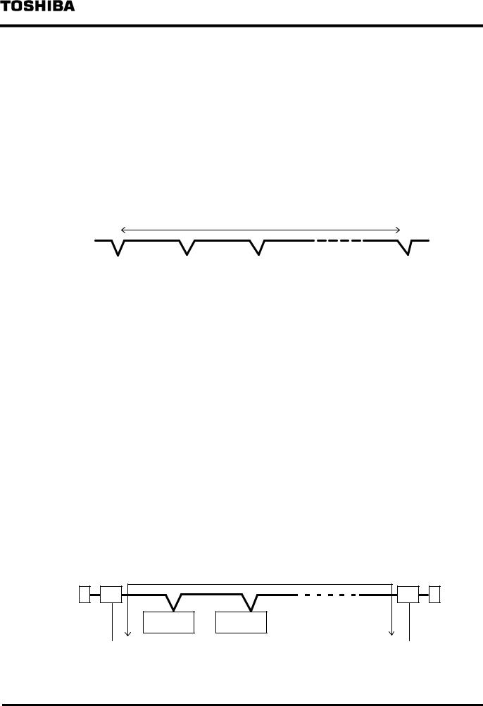
(3)The Maximum Cable Length
The distance between two nodes on the network cannot exceed the "Maximum cable length" specified in the DeviceNet specification. In Figure 1.4, the distance from node 0 to node 60 is not allowed to exceed the "Maximum cable length."
The "Maximum cable length" varies depending on the communication rate of the network and the type of the cable used for the trunk line .
a)Table 1.2 lists the maximum cable length for the case that the trunk line consists of a Thick Cable alone and no drop line is connected on it (that is, all nodes are connected on the trunk line), as shown in Figure 1.5. In this case, "maximum trunk line length between node 0 and node n" = "maximum cable length."
Moreover, when the "maximum trunk line length between node 0 and node n" = "maximum cable length," no new node can be attached outside node 0 and node n..
Terminal |
Distance between two nodes £ Maximum cable length |
Terminal |
||||||||||||||||||||||||
resistor |
|
|
|
|
|
|
|
|
|
|
|
|
|
|
|
|
|
|
|
resistor |
||||||
|
|
|
|
|
|
|
|
|
|
|
|
|
|
|
|
|
|
|
|
|
|
|
|
|
|
|
|
|
|
|
|
|
|
|
|
|
|
|
|
|
|
|
|
|
|
|
|
|
|
|
|
|
|
|
|
|
|
|
|
|
|
|
|
|
|
|
|
|
|
|
|
|
|
|
|
|
|
|
|
|
|
|
|
Node 0 |
|
Node 2 |
|
Node 3 |
|
∙ ∙ ∙ ∙ ∙ ∙ ∙ ∙ ∙ |
|
Node n |
|
|
|||||||||||||
|
|
|
|
|
|
|
|
|
|
|
|
|
|
|
|
|
|
|
|
|
|
|||||
|
|
|
|
|
|
|
|
|
|
|
|
|
|
|
|
|
|
|
|
|
|
|
|
|
|
|
Figure 1.5 Distance Between Two Nodes on a Network With No Drop Line
Table 1.2 Maximum Cable Length (Thick Cable/Thin Cable alone)
Communication |
Thick Cable |
Thin Cable alone |
|
Rate |
alone |
||
|
|||
|
|
|
|
|
|
|
|
125 kbps |
500 m |
100 m |
|
250 kbps |
250 m |
100 m |
|
500 kbps |
100 m |
100 m |
|
|
|
|
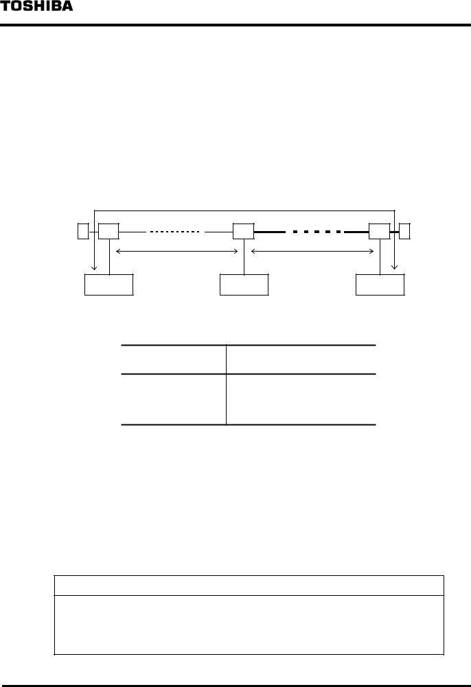
b)Figure 1.6 shows the maximum distance between two nodes in the case that a Thick Cable or Thin Cable alone is used for the trunk line and that drop lines are used.
Table 1.2. lists the maximum cable length. In this case, the "maximum trunk line length between two nodes" is as follows:
Maximum trunk line length between two nodes
=Maximum cable length (value in Table 1.2)
− Total length of drop lines for both ends nodes of trunk line
For Figure 1.6, the maximum trunk line length between node 0 and node n is equal to the maximum cable length (value in Table 1.2) minus total length of drop lines for node 0 and node n.
Terminal |
Distance between two nodes £ Maximum cable length |
Terminal |
resistor |
|
resistor |
Node 2 |
∙ |
∙ |
∙ |
∙ |
∙ |
∙ |
∙ |
∙ |
∙ |
Node 3 |
|
|
|
|
|
|
|
|
Node 0 |
|
Node n |
|
|
|
¾ 23 ¾

6 F 3 B 0 3 6 4
Figure 1.6 Distance Between Two Nodes on a Network with Drop Lines
¾ 24 ¾
6 F 3 B 0 3 6 4
c)Figure 1.7 shows the maximum distance between two nodes in the case that the trunk line consists of Thick Cable and Thin Cables and that drop lines are connected. Use the formulas in Table 1.3. for calculating the maximum cable length.
In this case, the "maximum trunk line length between two nodes" is represented in the following formula:
Maximum trunk line length between two nodes
=Maximum cable length (value in Table 1.3) − Total length of drop lines for the nodes at
both ends of trunk line
For Figure 1.7, the maximum trunk line length between node 0 and node n is equal to the maximum cable length (value in Table 1.3) minus the total length of the drop lines for node 0 and node n.
|
Distance between two nodes ≤ Maximum cable length |
|
||||||||||
Terminal |
|
|
|
|
|
|
|
|
|
|
|
Terminal |
resistor |
|
|
|
|
|
|
|
|
|
|
|
resistor |
|
|
|
|
L-thin |
|
|
|
|
|
L-thick |
|
|
Node 0 |
∙ |
∙ |
∙ |
∙ ∙ ∙ |
∙ |
∙ ∙ |
Node 3 |
∙ ∙ |
∙ |
∙ ∙ ∙ ∙ |
∙ ∙ |
Node n |
Figure 1.7 Distance Between Two Nodes on a Network with Drop Lines Table 1.3 Maximum Cable Length (Mixture of Thick Cable/Thin Cable)
Communication
Rate
125 kbps |
L-thick + 5 ´ L-thin £ 500 m |
250 kbps |
L-thick + 2.5 ´ L-thin £ 250 m |
500 kbps |
L-thick + L-thin £ 100 m |
L-thin: Length of trunk line using thin cable (m)
L-thick: Length of trunk line using thick cable (m)
1.2.3The Terminal Resistor
The DeviceNet needs a terminal resistor on both ends of the trunk line in order to reduce signal reflections and stabilize communications. The specifications of the terminal resistor are as follows:
∙121Ω
∙1% of the metal film
∙1/4 W
Terminal resistors conforming with the above specifications are available in the commercial market. See "3 .6 The Network Components."
Usage Recommendation
1.Don't make a network configuration whose extended trunk line and drop lines have no node being connected.
2.Don't attach a terminal resistor to the node. It could cause communication error.
3.Attach a terminal resistor to both ends of the trunk line; don't attach a terminal resistor on the
¾25 ¾

6 F 3 B 0 3 6 4
end of a drop line. Attach only to both ends of the trunk line.
¾ 26 ¾

6 F 3 B 0 3 6 4
1.3 Conformity Specification and Trademarks
DeviceNet is a standardized device level network for factory automation (FA), which is developed by RockWell Automation Co., Ltd. in USA. Currently, a nonprofit organization called ODVA (Open DeviceNet Vendor Association) is serving as the center for the maintenance and extensions of DeviceNet and introduction of conformable products.
The DeviceNet specification has Volume I: DeviceNet Communication Model and Protocol, and Volume II: DeviceNet Device Profiles and Object Library, in which the hardware and software specifications are defined.
The DeviceNet specification that the DN211 conforms with is found in Volume I, Release 1.3, and Volume II, Release 1.2.
Trademarks:
nDeviceNet is a registered trademark of ODVA (Open DeviceNet Vendor Association).
nPowerTap, T-Port Tap, DeviceBox Tap, and FLEX I/0 are registered trademarks of RockWell Automation Co., Ltd.
nCOMBICON is a registered trademark of Phoenix Contact Corporation.
¾ 27 ¾
6 F 3 B 0 3 6 4
1.4 The Basic Functions
This section describes the following two functions for communicating between the DN211 and slave devices.
1)Polling instruction/response mode
2)Bit strobe instruction/response mode
1.4.1The Polling Instruction/Response Mode
The polling instruction/response mode is used for exchanging an arbitrary size of data between the master device slave devices. The master device has information on slaves devices (items of scan list, such as node address, input/output data volume, etc.) on the network.
For polling instructions, based on such information, the master device outputs an arbitrary size of data to slave devices. Slave devices transmit response data (arbitrary data size) to a polling instruction to the master device (polling response).
It depends on the specification of a slave device how the slave device interprets the polling instruction and what data the slave device transmits as the polling response. For this communication function, it is prerequisite that the slave device supports the polling instruction/response mode. (Almost all the slave devices on the DeviceNet support this communication system).
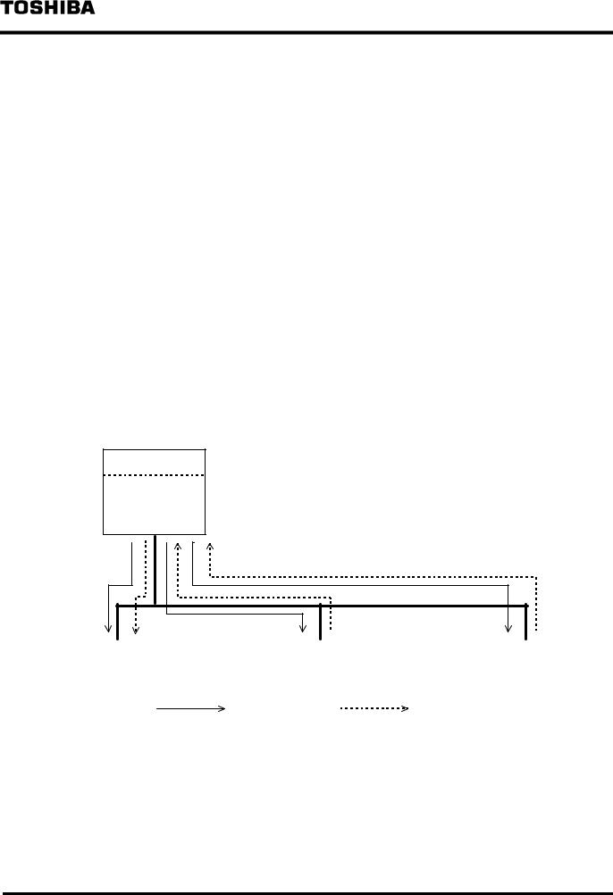
(1)The Polling Instruction
The example in Figure 1.8 indicates the DN211 is polling sensors, inputting sensor input information, and trying to send output control data to the actuator. How to write polling output data to the DN211 from the T2/T2E/T2N is found in "5. Communication with Slave Devices."
T2/T2E/T2N
Master
DN211
NA = 1
NA (Node Address):
Node identification number that individual DeviceNet devices have in the DeviceNet network. The values range from 0 to 63 in decimal scale.
In the DeviceNet network, the node addresses of the devices must be unique and different from each other.
Slave 1 |
|
Slave 3 |
|
Slave 5 |
Proximity sensor |
|
Optoelectronic sensor |
|
Actuator |
NA = 19 |
|
NA = 22 |
|
NA = 52 |
|
|
|
|
|
|
Polling instruction / |
Polling response |
||
Figure 1.8 Example of Polling Instruction/Response Mode
(2)The Polling Response
A slave device which received a polling instruction transmits an arbitrary size of response data to the master device. The content of response data varies depending on the specification of the slave device. The mechanism the T2/T2E/T2N reads polling response data from the DN211 is explained in"5. Communication with Slave Devices."
¾28 ¾
6 F 3 B 0 3 6 4
1.4.2The Bit Strobe Instruction/Response Mode
The bit strobe instruction/response mode is used for exchanging a small size of data between the master device slave devices. In the bit strobe instruction, based on the information obtained from the scan list, the master device broadcasts 1-bit output data to individual slave devices.
These individual devices transmit data (0-8 bytes) in response to the bit strobe instruction to the master device (bit strobe response).
It depends on the specification of a slave device how the salve device interprets a bit strobe instruction and what data the slave device transmits to the bit strobe response.
For this communication function, it is prerequisite that the slave device supports the bit strobe instruction/response mode.
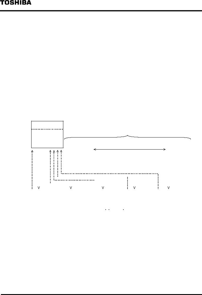
(1)The Bit Strobe Instruction
Broadcasts data to bit strobe instruction/response mode supporting slave devices on the network. The bit strobe instruction contains 64-bit output data, and each of the 64 bits is assigned to individual node addresses on the network (Figure 1. 9).
The example in Figure 1.9 indicates the DN211 is inputting sensor information by the bit strobe mode and trying to send output control data to the actuator. The way of writing output data in bit strobe from the T2/T2E/T2N to the DN211 is explained in "5. Communication with Salve Devices."
T2/T2E/T2N |
Bit strobe instruction data |
|
Master |
||
|
||
DN211 |
|
|
NA = 1 |
Bit number |
|
|
|
|
|
|
|
|
|
|
|
|
|
|
|
|
|
|
|
|
|
|
|
|
|
|
|
|
|
|
|
|
0 |
|
1 |
∙ ∙ ∙ ∙ |
19 |
|
20 |
21 |
22 |
23 |
24 |
∙ ∙ ∙ ∙ |
51 |
52 |
∙ ∙ ∙ ∙ |
63 |
||||||||
|
|
|
|
|
|
|
|
|
|
|
|
|
|
|
|
|
|
|
|
|
|
|
|
|
|
|
|
|
|
|
|
|
|
|
|
|
|
|
|
|
|
|
|
|
|
|
|
|
|
|
|
|
|
|
|
|
|
|
|
|
|
|
|
|
|
|
|
|
|
|
|
|
|
|
|
|
|
|
|
|
|
|
|
|
|
|
|
|
|
|
|
|
|
|
|
|
|
|
|
|
|
|
|
|
|
|
|
|
|
|
|
|
|
|
|
|
|
|
|
|
|
|
|
|
|
|
|
|
|
|
|
|
|
|
|
|
|
|
|
|
|
|
|
|
|
|
|
|
|
|
|
|
|
|
|
|
|
|
|
|
|
|
|
|
|
|
|
|
|
|
|
|
|
|
|
|
|
|
|
|
|
|
|
|
|
|
|
|
Slave 1 |
|
Slave 2 |
|
Slave 3 |
|
Slave 4 |
|
Slave 5 |
|
|
Photoelectric |
|
Photoelectric |
|
|||
Proximity sensor |
|
Proximity sensor |
|
|
|
Actuator |
||
|
|
sensor |
|
sensor |
|
|||
NA = 19 |
|
NA = 21 |
|
|
|
NA = 52 |
||
|
|
NA = 22 |
|
NA = 23 |
|
|||
|
|
|
|
|
|
|
 Bit strobe instruction /


 Bit strobe response
Figure 1.9 Example of the Bit Strobe Instruction/Response Mode
(2)The Bit Strobe Response
A slave device which received the bit strobe instruction transmits 0 to 8 byte response data to the master device. The contents of response data varies depending on the specification of the slave device. The way the T2/T2E/T2N reads bit-strobe response data from the DN211 is described in "5. Communication with Slave Devices."
¾ 29 ¾
 Loading...