


 Loading...
Toshiba Personal Computer
Satellite & Satellite Pro
Maintenance Manual
TOSHIBA CORPORATION
[CONFIDENTIAL]

Copyright
© 2009 by Toshiba Corporation. All rights reserved. Under the copyright laws, this manual cannot be reproduced in any form without the prior written permission of Toshiba. No patent liability is assumed with respect to the use of the information contained herein.
Toshiba Personal Computer Satellite & SatellitePro Maintenance Manual
First edition April. 2010
Disclaimer
The information presented in this manual has been reviewed and validated for accuracy. The included set of instructions and descriptions are accurate for the Satellite Series at the time of this manual's production. However, succeeding computers and manuals are subject to change without notice. Therefore, Toshiba assumes no liability for damages incurred directly or indirectly from errors, omissions, or discrepancies between any succeeding product and this manual.
Trademarks
IBM is a registered trademark, and OS/2 and PS/2 are trademarks of IBM Corporation. Microsoft, MS-DOS, Windows, DirectSound and DirectMusic are registered trademarks of Microsoft Corporation.
Intel and Pentium are registered trademarks, and SpeedStep is a trademark of Intel Corporation. Sound Blaster is a registered trademark of Creative Technology Ltd.
Centronics is a registered trademark of Centronics Data Computer Corporation. Photo CD is a trademark of Eastman Kodak.
All other properties are trademarks or registered trademarks of their respective holders.
ii |
[CONFIDENTIAL] Satellite L670/L675/ Pro L670/L675 Series Maintenance Manual |
Preface
This maintenance manual describes how to perform hardware service maintenance for the Toshiba Personal Computer Satellite, referred to as the Satellite Series in this manual.
The procedures described in this manual are intended to help service technicians isolate faulty Field Replaceable Units (FRUs) and replace them in the field.
SAFETY PRECAUTIONS
Four types of messages are used in this manual to bring important information to your attention. Each of these messages will be italicized and identified as shown below.
DANGER: “Danger” indicates the existence of a hazard that could result in death or serious bodily injury if the safety instruction is not observed.
WARNING: “Warning” indicates the existence of a hazard that could result in bodily injury if the safety instruction is not observed.
CAUTION: “Caution” indicates the existence of a hazard that could result in property damage if the safety instruction is not observed.
NOTE: “Note” contains general information that relates to your safe maintenance service.
Improper repair of the computer may result in safety hazards. Toshiba requires service technicians and authorized dealers or service providers to ensure the following safety precautions are adhered to strictly.
Be sure to fasten screws securely with the right screwdriver. If a screw is not fully fastened, it could come loose, creating a danger of a short circuit, which could cause overheating, smoke or fire.
If you replace the battery pack or RTC battery, be sure to use only the same model battery or an equivalent battery recommended by Toshiba. Installation of the wrong battery can cause the battery to explode.
Satellite L670/L675/ProL670/L675 Series Maintenance Manual |
[CONFIDENTIAL] |
iii |

The manual is divided into the following parts:
Chapter 1 Hardware Overview describes the Satellite Series system unit and each FRU.
Chapter 2 Troubleshooting Procedures explains how to diagnose and resolve FRU problems.
Chapter 3 Test and Diagnostics describes how to perform test and diagnostic operations for maintenance service.
Chapter 4 Replacement Procedures describes the removal and replacement of the FRUs.
Appendices The appendices describe the following:
Handling the LCD module
Board layout
Pin assignments
Keyboard scan/character codes
Key layout
Screw torque list
Reliability
Conventions
This manual uses the following formats to describe, identify, and highlight terms and operating procedures.
Acronyms
On the first appearance and whenever necessary for clarification, acronyms are enclosed in parentheses following their definition. For example:
Read Only Memory (ROM)
Keys
Keys are used in the text to describe many operations. The key top symbol as it appears on the keyboard is printed in boldface type.
Key operation
iv |
[CONFIDENTIAL] Satellite L670/L675/ Pro L670/L675 Series Maintenance Manual |

Some operations require you to simultaneously use two or more keys. We identify such operations by the key top symbols separated by a plus (+) sign. For example, Ctrl + Pause (Break) means you must hold down Ctrl and at the same time press Pause (Break). If three keys are used, hold down the first two and at the same time press the third.
User input
Text that you are instructed to type in is shown in the boldface type below:
DISKCOPY A: B:
The display
Text generated by the computer that appears on its display is presented in the typeface below:
Format complete
System transferred
Satellite L670/L675/ProL670/L675 Series Maintenance Manual |
[CONFIDENTIAL] |
v |

Table of Contents
Chapter 1 Hardware Overview |
|
|
1.1 |
Features............................................................................................................................. |
1-1 |
1.2 |
2.5-inch HDD ................................................................................................................. |
1-10 |
1.3 |
DVD Super Multi (+-R Double Layer) .......................................................................... |
1-11 |
1.4BD-Writer and BD-Combo drives……………………………………………………..1-12
1.5 |
Power Supply.................................................................................................................. |
1-13 |
|
1.6 |
Batteries .......................................................................................................................... |
1-15 |
|
|
1.6.1 |
Main Battery..................................................................................................... |
1-15 |
|
1.6.2 |
Battery Charging Control ................................................................................. |
1-15 |
|
1.6.3 |
RTC Battery...................................................................................................... |
1-16 |
Chapter 2 Troubleshooting Procedures |
|
|
2.1 |
Troubleshooting Introduction.............................................................................................. |
3 |
2.2 |
Troubleshooting Flowchart.................................................................................................. |
4 |
2.3 |
Power Supply Troubleshooting ........................................................................................... |
9 |
2.4 |
Display Troubleshooting ................................................................................................... |
14 |
2.5 |
Keyboard Troubleshooting ................................................................................................ |
17 |
2.6 |
External USB Devices Troubleshooting............................................................................ |
19 |
2.7 |
TouchPad Troubleshooting................................................................................................ |
21 |
2.8 |
Speaker Troubleshooting................................................................................................... |
23 |
2.9 |
Optical Drive Troubleshooting.......................................................................................... |
25 |
2.10 |
Modem Troubleshooting .................................................................................................. |
28 |
2.11 |
Wireless LAN Troubleshooting......................................................................................... |
30 |
2.12 |
Camera Troubleshooting ................................................................................................... |
32 |
2.13Bluetooth Troubleshooting…………………...…………………………….……….. 34
2.14Bridge Media slot Troubleshooting……………………………………………..…... 36
vi |
[CONFIDENTIAL] Satellite L670/L675/ Pro L670/L675 Series Maintenance Manual |

2.15HDD Troubleshooting………………………………………………………………..38
2.16CRT failure Troubleshooting ……………………………………………………….. 40
2.17HDMI Troubleshooting …………………………………………………………….. 42
2.18MIC Troubleshooting ………………………………………………………………. 44
2.19E-SATA Troubleshooting ………………………………………….……………….. 46
2.20LAN Troubleshooting………………………………………………………………...48
Figures |
|
|
|
Figure 2-1 |
Troubleshooting Flowchar(1/2) |
|
|
|
………………………………………………Fehler! Textmarke nicht definiert. |
||
Figure 2-1 Troubleshooting Flowchart (2/2) |
|
|
|
|
……………………………………………...Fehler! Textmarke nicht definiert. |
||
Figure 2-2 |
Power Supply Troubleshooting Process……………………………………….9 |
||
Figure 2-3 |
Display Troubleshooting Process ............. |
Fehler! Textmarke nicht definiert. |
|
Figure 2-4 |
Keyboard Troubleshooting Process ................................................................. |
|
17 |
Figure 2-5 |
External USB Device Troubleshooting Process |
..............................................19 |
|
Figure 2-6 |
TouchPad Troubleshooting Process................................................................. |
|
21 |
Figure 2-7 |
Speaker Troubleshooting Process.................................................................... |
|
23 |
Figure 2-8 |
Optical Drive Troubleshooting Process........................................................... |
|
25 |
Figure 2-9 |
Modem Troubleshooting Process………………………...…………………..28 |
||
Figure 2-10 |
Wireless LAN Troubleshooting Process………………………………...…...30 |
||
Figure 2-11 |
Camera Troubleshooting Process…………………………………………….32 |
||
Figure 2-12 |
Bluetooth Troubleshooting Process…..…………..………………….……….34 |
||
Figure 2-13 |
3 in 1 Card TroubleshootingProcess…………………………..…….………..36 |
||
Figure 2-14 |
HDD Troubleshooting Process…………………………….………………....38 |
||
Figure 2-15 |
CRT Failure Troubleshooting Process ………………………..……………...40 |
||
Figure 2-16 |
HDMI Troubleshooting Process …………………………………………......42 |
||
Figure 2-17 |
MIC Troubleshooting Process ………………………….……………….…...44 |
||
Figure 2-18 |
E-SATA Troubleshooting Process ……………………...….………………...46 |
||
Figure 2-19 |
LAN Troubleshooting Process …………………...…….………………….....48 |
||
Satellite L670/L675/ProL670/L675 Series Maintenance Manual |
[CONFIDENTIAL] |
vii |

Chapter 3 Tests and Diagnostics |
|
|
3.1 |
The Diagnostic Test.................................................... |
Fehler! Textmarke nicht definiert. |
3.2 |
Executing the Diagnostic Test .................................... |
Fehler! Textmarke nicht definiert. |
3.3 |
Display Configuration ................................................ |
Fehler! Textmarke nicht definiert. |
3.4 |
Audio Sound Test ................................................................................................................ |
8 |
3.5 |
Fan ON/OFF Test .............................................................................................................. |
11 |
3.6 |
Main Battery Charge Test.................................................................................................. |
13 |
3.7FDD Test........................................................................................................................…15
3.8 |
Memory Check .................................................................................................................. |
16 |
3.9 |
Keyboard Test.................................................................................................................... |
19 |
3.10 |
Mouse (Pad) Test............................................................................................................... |
21 |
3.11 |
LCD Pixels Mode Test ...................................................................................................... |
22 |
3.12 |
Magnetic Switch Test ........................................................................................................ |
23 |
3.13 |
LAN Test ........................................................................................................................... |
25 |
3.14 |
RTC Test............................................................................................................................ |
27 |
3.151st HDDTest ……………………………....……….…….……………....….……….......28
3.16Read DMI Test………………...….………………….………………...…..……….….....31
3.17Write DMI Test …………….…………………………..………....…....….………........32
3.18EEPROM Setting ………………………..………………………………………….…...34
3.19TOSHIBA Logo Setting…………………..…………………………………………...…..37
3.20 DYNABOOK Logo Setting.............................................................................................. |
39 |
Chapter 4 Replacement Procedures |
|
|
4.1 |
General........................................................................ |
Fehler! Textmarke nicht definiert. |
|
Safety Precautions....................................................... |
Fehler! Textmarke nicht definiert. |
|
Before You Begin ....................................................... |
Fehler! Textmarke nicht definiert. |
|
Disassembly Procedures.............................................. |
Fehler! Textmarke nicht definiert. |
viii |
[CONFIDENTIAL] Satellite L670/L675/ Pro L670/L675 Series Maintenance Manual |

|
Assembly Procedures .................................................. |
Fehler! Textmarke nicht definiert. |
|
Tools and Equipment .................................................. |
Fehler! Textmarke nicht definiert. |
|
Screw Tightening Torque............................................ |
Fehler! Textmarke nicht definiert. |
|
Colors of Screw Shanks .............................................. |
Fehler! Textmarke nicht definiert. |
|
Symbols of Screws on the Laptop Body ..................... |
Fehler! Textmarke nicht definiert. |
|
Symbol examples ........................................................ |
Fehler! Textmarke nicht definiert. |
4.2 |
Battery......................................................................... |
Fehler! Textmarke nicht definiert. |
|
Removing the Battery Pack......................................... |
Fehler! Textmarke nicht definiert. |
|
Installing the Battery Pack .......................................... |
Fehler! Textmarke nicht definiert. |
4.3 |
HDD............................................................................ |
Fehler! Textmarke nicht definiert. |
|
Removing the HDD..................................................... |
Fehler! Textmarke nicht definiert. |
|
Installing the HDD ...................................................... |
Fehler! Textmarke nicht definiert. |
4.4 |
Memory....................................................................... |
Fehler! Textmarke nicht definiert. |
|
Removing the Optional Memory................................. |
Fehler! Textmarke nicht definiert. |
|
Installing the Optional Memory .................................. |
Fehler! Textmarke nicht definiert. |
4.5 |
ODD............................................................................ |
Fehler! Textmarke nicht definiert. |
|
Removing the ODD..................................................... |
Fehler! Textmarke nicht definiert. |
|
Installing the ODD ...................................................... |
Fehler! Textmarke nicht definiert. |
|
Disassembling the ODD.............................................. |
Fehler! Textmarke nicht definiert. |
|
Assembling the ODD Drive ........................................ |
Fehler! Textmarke nicht definiert. |
4.6 |
Keyboard Cover and Keyboard .................................. |
Fehler! Textmarke nicht definiert. |
|
Removing the Keyboard Cover and Keyboard ........... |
Fehler! Textmarke nicht definiert. |
|
Installing the Keyboard Cover and Keyboard............. |
Fehler! Textmarke nicht definiert. |
4.7 |
Logic Upper Assembly ............................................... |
Fehler! Textmarke nicht definiert. |
|
Removing the Logic Upper Assembly ........................ |
Fehler! Textmarke nicht definiert. |
|
Installing the Logic Upper Assembly ......................... |
Fehler! Textmarke nicht definiert. |
4.8 |
Touchpad FFC ............................................................ |
Fehler! Textmarke nicht definiert. |
|
Removing the Touchpad FFC ..................................... |
Fehler! Textmarke nicht definiert. |
|
Installing the Touchpad FFC....................................... |
Fehler! Textmarke nicht definiert. |
4.9 |
WLAN Card................................................................ |
Fehler! Textmarke nicht definiert. |
|
Removing the WLAN Card......................................... |
Fehler! Textmarke nicht definiert. |
Satellite L670/L675/ProL670/L675 Series Maintenance Manual |
[CONFIDENTIAL] |
ix |

|
Installing the WLAN card........................................... |
Fehler! Textmarke nicht definiert. |
4.10 |
Modem Card ............................................................... |
Fehler! Textmarke nicht definiert. |
|
Removing the Modem Card ........................................ |
Fehler! Textmarke nicht definiert. |
|
Installing the Modem Card.......................................... |
Fehler! Textmarke nicht definiert. |
4.11 |
USB Board.................................................................. |
Fehler! Textmarke nicht definiert. |
|
Removing the Right USB Board on the Right Side.... |
Fehler! Textmarke nicht definiert. |
|
Installing the Right USB Board .................................. |
Fehler! Textmarke nicht definiert. |
4.12 |
ODD Board ................................................................. |
Fehler! Textmarke nicht definiert. |
|
Removing the ODD Board.......................................... |
Fehler! Textmarke nicht definiert. |
|
Installing the ODD switch board ................................ |
Fehler! Textmarke nicht definiert. |
4.13 |
Touchpad Button Board.............................................. |
Fehler! Textmarke nicht definiert. |
|
Removing the Touchpad Button Board....................... |
Fehler! Textmarke nicht definiert. |
|
Installing the touchpad button switch board ............... |
Fehler! Textmarke nicht definiert. |
4.14 |
Power Board ............................................................... |
Fehler! Textmarke nicht definiert. |
|
Removing the Power Board ........................................ |
Fehler! Textmarke nicht definiert. |
|
Installing the Power Board.......................................... |
Fehler! Textmarke nicht definiert. |
4.15 |
Bluetooth Card............................................................ |
Fehler! Textmarke nicht definiert. |
|
Removing the Bluetooth card...................................... |
Fehler! Textmarke nicht definiert. |
|
Installing the Bluetooth card ....................................... |
Fehler! Textmarke nicht definiert. |
4.16 |
Display Assembly ....................................................... |
Fehler! Textmarke nicht definiert. |
|
Removing the Display Assembly................................ |
Fehler! Textmarke nicht definiert. |
|
Installing the Display Assembly ................................. |
Fehler! Textmarke nicht definiert. |
4.17 |
Thermal Fan................................................................ |
Fehler! Textmarke nicht definiert. |
|
Removing the Thermal Fan......................................... |
Fehler! Textmarke nicht definiert. |
|
Installing the Thermal Fan .......................................... |
Fehler! Textmarke nicht definiert. |
4.18 |
Motherboard................................................................ |
Fehler! Textmarke nicht definiert. |
|
Removing the Motherboard ........................................ |
Fehler! Textmarke nicht definiert. |
|
Installing the Motherboard.......................................... |
Fehler! Textmarke nicht definiert. |
4.19 |
Speakers...................................................................... |
Fehler! Textmarke nicht definiert. |
|
Removing the Speakers............................................... |
Fehler! Textmarke nicht definiert. |
|
Installing the Speakers ................................................ |
Fehler! Textmarke nicht definiert. |
x |
[CONFIDENTIAL] Satellite L670/L675/ Pro L670/L675 Series Maintenance Manual |
4.20 |
RJ11 Cable.................................................................. |
Fehler! Textmarke nicht definiert. |
|
Removing the RJ11 Cable........................................... |
Fehler! Textmarke nicht definiert. |
|
Installing the RJ11 Cable ............................................ |
Fehler! Textmarke nicht definiert. |
4.21 |
CPU and Thermal Module.......................................... |
Fehler! Textmarke nicht definiert. |
|
Removing the CPU and Thermal Module................... |
Fehler! Textmarke nicht definiert. |
|
Installing the CPU and Thermal Module .................... |
Fehler! Textmarke nicht definiert. |
4.22 |
LCD Bezel .................................................................. |
Fehler! Textmarke nicht definiert. |
|
Removing the LCD Bezel ........................................... |
Fehler! Textmarke nicht definiert. |
|
Install the LCD bezel assembly according to the following procedures.Fehler! Textmarke |
|
|
nicht definiert. |
|
4.23 |
LCD Module ............................................................... |
Fehler! Textmarke nicht definiert. |
|
Removing the LCD Module........................................ |
Fehler! Textmarke nicht definiert. |
|
Installing the LCD Panel............................................. |
Fehler! Textmarke nicht definiert. |
4.24 |
Camera Module........................................................... |
Fehler! Textmarke nicht definiert. |
|
Removing the Camera Module ................................... |
Fehler! Textmarke nicht definiert. |
|
Installing the Camera Module..................................... |
Fehler! Textmarke nicht definiert. |
4.25 |
Antennas for WLAN................................................... |
Fehler! Textmarke nicht definiert. |
|
Removing the Antennas for WLAN............................ |
Fehler! Textmarke nicht definiert. |
|
Installing the Antennas for WLAN ............................. |
Fehler! Textmarke nicht definiert. |
Figures |
|
|
Figure 4.1 Removing the Battery Pack............................. |
Fehler! Textmarke nicht definiert. |
|
Figure 4.2 Removing the logic lower door ....................... |
Fehler! Textmarke nicht definiert. |
|
Figure 4.3 Removing the HDD from the HDD bay.......... |
Fehler! Textmarke nicht definiert. |
|
Figure 4.4 Removing the HDD aluminum........................ |
Fehler! Textmarke nicht definiert. |
|
Figure 4.5 |
Installing the HDD aluminum ......................... |
Fehler! Textmarke nicht definiert. |
Figure 4.6 |
Installing the logic lower door......................... |
Fehler! Textmarke nicht definiert. |
Figure 4.7 |
Removing the RAM from the connectors ....... |
Fehler! Textmarke nicht definiert. |
Satellite L670/L675/ProL670/L675 Series Maintenance Manual |
[CONFIDENTIAL] |
xi |
Figure 4.8 |
Removing the ODD......................................... |
Fehler! Textmarke nicht definiert. |
|
Figure 4.9 |
Removing the ODD bracket from the ODD.... |
Fehler! Textmarke nicht definiert. |
|
Figure 4.10 |
Removing the keyboard cover....................... |
Fehler! Textmarke nicht definiert. |
|
Figure 4.11 |
Removing screws securing the keyboard ...... |
Fehler! Textmarke nicht definiert. |
|
Figure 4.12 |
Removing the keyboard................................. |
Fehler! Textmarke nicht definiert. |
|
Figure 4.13 |
Removing twenty-one screws from the bottom of the laptopFehler! Textmarke nicht |
||
|
|
definiert. |
|
Figure 4.14 Removing five screws and disconnecting one FFC from the motherboard Fehler!
Textmarke nicht definiert.
Figure 4.15 Removing the logic upper assembly from the laptop.....Fehler! Textmarke nicht
definiert. |
|
Figure 4.16 Removing the touchpad FFC......................... |
Fehler! Textmarke nicht definiert. |
Figure 4.17 Removing the WLAN Card........................... |
Fehler! Textmarke nicht definiert. |
Figure 4.18 |
Removing two screws securing the modem cardFehler! Textmarke nicht definiert. |
Figure 4.19 |
Disconnecting the cable from the modem cardFehler! Textmarke nicht definiert. |
Figure 4.20 |
Disconnecting the FFC from the motherboardFehler! Textmarke nicht definiert. |
Figure 4.21 |
Disconnecting the ODD board FFC .............. |
Fehler! Textmarke nicht definiert. |
Figure 4.22 |
Removing the touchpad button board ........... |
Fehler! Textmarke nicht definiert. |
Figure 4.23 Disconnecting the FFC from the motherboardFehler! Textmarke nicht definiert.
Figure 4.24 |
Removing the power board ........................... |
Fehler! Textmarke nicht definiert. |
Figure 4.25 |
Removing the Bluetooth card........................ |
Fehler! Textmarke nicht definiert. |
Figure 4.26 |
Disconnecting the Bluetooth cable................ |
Fehler! Textmarke nicht definiert. |
Figure 4.27 |
Removing the display assembly.................... |
Fehler! Textmarke nicht definiert. |
Figure 4.28 Removing the thermal fan from the logic lower assemblyFehler! Textmarke nicht definiert.
Figure 4.29 Removing the motherboard from the logic lower assemblyFehler! Textmarke nicht
definiert. |
|
Figure 4.30 Removing the speakers.................................. |
Fehler! Textmarke nicht definiert. |
Figure 4.31 Pulling out the cable from the routing channelFehler! Textmarke nicht definiert.
Figure 4.32 Removing the RJ11 connector ...................... |
Fehler! Textmarke nicht definiert. |
|
Figure 4.33 |
Removing the Thermal Module spring screwsFehler! Textmarke nicht definiert. |
|
Figure 4.34 |
Removing the Thermal Module spring screwsFehler! Textmarke nicht definiert. |
|
Figure 4.35 |
Removing the CPU........................................ |
Fehler! Textmarke nicht definiert. |
|
|
|
xii |
[CONFIDENTIAL] Satellite L670/L675/ Pro L670/L675 Series Maintenance Manual |
|

Figure 4.36 Reapply the Shinetsu 7726 grease on the thermal module and remove any release
|
papers ........................................................ |
Fehler! Textmarke nicht definiert. |
Figure 4.37 |
Removing the LCD Bezel ............................. |
Fehler! Textmarke nicht definiert. |
Figure 4.38 |
Prying up the LCD Bezel .............................. |
Fehler! Textmarke nicht definiert. |
Figure 4.39 |
Removing the LCD Bezel ............................. |
Fehler! Textmarke nicht definiert. |
Figure 4.40 Removing the LCD Module from the LCD cover assemblyFehler! Textmarke nicht
|
definiert. |
|
Figure 4.41 Disconnect the camera module cable ............ |
Fehler! Textmarke nicht definiert. |
|
Figure 4.42 Removing the LCD hinges ............................ |
Fehler! Textmarke nicht definiert. |
|
Figure 4.43 |
Removing the LVDS cable from the LCD panelFehler! Textmarke nicht definiert. |
|
Figure 4.44 |
Installing the LCD hinges.............................. |
Fehler! Textmarke nicht definiert. |
Figure 4.45 |
Removing the Camera Module...................... |
Fehler! Textmarke nicht definiert. |
Figure 4.46 |
Removing the antennas from the LCD cover assembly Fehler! Textmarke nicht |
|
|
definiert. |
|
Appendices |
|
|
Appendix A |
Handling the LCD Module .................................................................................... |
A-1 |
Appendix B |
Board Layout ......................................................................................................... |
B-1 |
Appendix C |
Pin Assignments..................................................................................................... |
C-1 |
Appendix D |
Keyboard Scan/Character Codes ........................................................................... |
D-1 |
Appendix E |
Key Layout............................................................................................................. |
E-1 |
Appendix F |
Series Screw Torque List....................................................................................... |
F-1 |
Appendix G |
Reliability............................................................................................................... |
G-1 |
Satellite L670/L675/ProL670/L675 Series Maintenance Manual |
[CONFIDENTIAL] |
xiii |

1 Hardware Overview
Chapter 1
Hardware Overview
Satellite L670/Pro L670 Maintenance Manual[CONFIDENTIAL]

1 Hardware Overview
Chapter 1 |
Contents |
|
|
1.1 |
Features |
.................................................................................................................. |
1-1 |
1.2 |
2.5-inch .......................................................................................................HDD |
1-10 |
|
1.3 |
DVD Super ................................................................Multi (+-R Double Layer) |
1-11 |
|
1.4 |
BD-Writer .......................................................................and BD-Combo drives |
1-12 |
|
1.5 |
Power Supply ....................................................................................................... |
1-13 |
|
1.6 |
Batteries................................................................................................................ |
|
1-15 |
|
1.6.1 ......................................................................................... |
Main Battery |
1-15 |
|
1.6.2 ..................................................................... |
Battery Charging Control |
1-15 |
|
1.6.3 .......................................................................................... |
RTC Battery |
1-16 |
[CONFIDENTIAL] Satellite L670/Pro L670 Maintenance Manual

1 Hardware Overview
Figures |
|
|
Figure 1-1A |
ID Parts Description Placement Part A.......................................................... |
1-5 |
Figure 1-2 |
SATA HDD ................................................................................................. |
1-10 |
Figure 1-3 |
DVD Super Multi Drive .............................................................................. |
1-11 |
Figure 1-4 |
BD-Writer or BD-Combo drive (depending on the model)......................... |
1-12 |
Tables |
|
|
Table 1-1 |
HDD Specifications ..................................................................................... |
1-10 |
Table 1-2 |
DVD Super Multi Drive Specifications....................................................... |
1-11 |
Table 1-3 |
Blu-ray Disc Drive specifications................................................................ |
1-12 |
Table 1-4 |
Quick/Normal Charging Time ..................................................................... |
1-15 |
Satellite L670/Pro L670 Maintenance Manual[CONFIDENTIAL]

1.1 Features |
1 Hardware Overview |
1.1Features
The Toshiba Satellite L670/Pro L670 is a full-size PC notebook equipped with a Dual Core Processor, providing high-speed processing capabilities and advanced features. The computer employs a lithium ion battery that allows it to be battery-operated for long periods of time. The display uses 17.3-inch WXGA LCD panel. Many features can be Built To Order (BTO) to customize the system for each user.
The computer has the following features:
Processor (BTO)
The computer is equipped with one of the following Intel® processors:Intel® Arrandale Processor
Memory (BTO)
The computer has two SODIMM slots which come standard with 1GB/2GB/4GB, accepting BTO for your memory requirements. It can incorporate up to 8 GB of main memory and supports DDR3 at 1333MHz (Works as 1066MHz)/1066MHz/800MHz.
Battery Pack
The computer is powered by one rechargeable and removable lithium ion battery pack. The capacity can be either 3-cell, 6-cell or 12-cell, depending on the model of the computer.
RTC Battery
The internal RTC battery backs up the Real Time Clock and calendar.
Hard Disk Drive (HDD) (BTO)
The computer accommodates a 9.5 mm HDD with the following storage capacities: y 250/320/400/500/640 GB, S-ATA (5,400rpm)
y 500 GB, S-ATA (7,200rpm)
[CONFIDENTIAL]Satellite L670/Pro L670 Maintenance Manual

1 Hardware Overview |
1.1 Features |
|
|
|
|
ODD (BTO)
y12.7mm height DVD Super Multi drive supporting ±R Double Layer
y12.7mm height DVD Super Multi drive supporting ±R Double Layer w/ Labelflash
y12.7mm height BD-Combo drive
y12.7mm height BD Writer drive
Display
The LCD display comes with the following:
y17.3" W (16:9) HD+ (1600x900) LED CSV and Non-CSV Type.
Graphics (BTO)
Mobile Intel® HM55/HM57 Chipset for integrated graphics display
ATI Mobility RadeonTM HD 5145/HD5470/HD5650 (DDR3, 1024MB)for external graphics support
(depending on model)
Keyboard
The computer is equipped with a Toshiba standard 360mm keyboard, which has A4 + 10key Genchaku Keyboard without stick-point. It is a Win7-compliant keyboard with optional Windows keys and application keys.
Pointing Device
The integrated Wide Touch Pad and two control buttons in the palm rest allow control of the on-screen pointer and support functions such as the scrolling of windows.
External Monitor Port
The analog VGA port provides support for VESA DDC2B compatible functions. A WDDM driver is ready for Win7.
Universal Serial Bus (USB) Ports
The computer has two USB 2.0 ports along with one USB/eSATA combo port (see below). It is supported to daisy-chain a maximum of 127 USB devices. The serial data transfer rate is 480 Mbps or 12 Mbps and 1.5 Mbps. These ports support PnP installation and hot plugging.
Satellite L670/Pro L670 Maintenance Manual[CONFIDENTIAL]

1.1 Features |
1 Hardware Overview |
eSATA
The external SATA or eSATA port executes high-speed data transfer to external devices and supports shielded cable lengths of up to 2 meters outside the PC. The port also provides dual USB compatibility.
Bridge Media Slot
This slot allows you to insert SD/SDHC/SDXC memory card, miniSD/microSD Card, Memory Stick (PRO), and MultiMediaCard. It supports high-speed SD, SDHC and SDXC. This model does not support CF, SmartMedia cards, xD or Memory Stick Duo cards.
Sound system
The integrated sound system is composed of two Realtek Azalia internal speakers, an internal microphone (BTO with internal camera), and standard Microphone-IN and Headphone-OUT ports. Dolby® Advanced Audio function is also integrated in the system.
Internal Camera (BTO)
It supports 0.3M and 1.3M pixels with Auto Macro and comes with a blue LED indicator. An internal microphone is BTO with the internal camera and includes echo cancellation. The camera is not a rotation type.
Headphones/Line-out Jack
This jack connects digital speakers or stereo headphones (16 ohm minimum). When connected to digital speakers or headphones, the internal speaker is automatically disabled.
Microphone/ Line-in Jack
A 3.5mm mini microphone jack enables connection of a three-conductor microphone for monaural input and also enables the connection of a stereo device for audio input.
HDMI Out Port (BTO)
The HDMI out port can connect with a Type A connector HDMI cable. The HDMI out port can send SD and HD video/audio signals.
[CONFIDENTIAL]Satellite L670/Pro L670 Maintenance Manual

1 Hardware Overview |
1.1 Features |
|
|
|
|
LAN (BTO)
The computer has built-in support for 10M/100M Ethernet LAN (10/100 megabits per second, 10/100BASE-T). It employs a Realtek RTL8105E for 10M/100Mbit LAN (for discrete platform, Realtek RTL8111E for 10M/100M/1000M is employed). It is preinstalled as a standard device in some markets.
Wireless LAN (BTO)
Some computers in this series are equipped with a Wireless LAN (WLAN) card. This WLAN module may come with the following types (depending on the model):
Atheros 802.11 b/g (HB95 1x1n)
Realtek 802.11 b/g/n (8191SE)
Internal Modem (BTO)
Some models are equipped with an integrated modem. The integrated modem provides capability for data and fax communications that support the V.90 (V.92) standards and includes a modem jack for connection to the telephone line. Please note that both the V.90 and V.92 standards are only supported in the USA, Canada, United Kingdom, France, Germany and Australia - only the V.90 standard is supported in other regions. You should also be aware that the speed of data and fax transfer will depend on the analog telephone line conditions. The integrated model is only installed as a standard device in some markets. This internal modem comes with MDC 1.5 solution (Azalia interface).
Bluetooth (BTO)
Some computers in this series offer Bluetooth wireless communication functionality which eliminates the need for cables between electronic devices such as computers and printers. When implemented, Bluetooth provides wireless communication in a small space. This module is Version 2.1 + EDR (BCM2070 Flash SLIM with Antenna), ie – Toshiba stack support.
Satellite L670/Pro L670 Maintenance Manual[CONFIDENTIAL]

1.1 Features |
1 Hardware Overview |
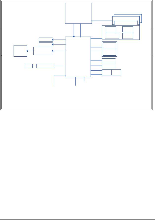
Figure 1-1A shows the computer and its system unit configuration.
CAMERA
|
Printing sub-brand |
SPEAKER |
SPEAKER |
THERMAL VAN HOLES |
|
VGA |
|
RJ45 |
|
eSATA/USB |
|
HDMI |
TOUCH PAD ON/OFF BTN |
|
TOUCH PAD |
|
TP BTN |
Bridge Media Slot |
|


 KENSINGTON LOCK
 ODD
ODD
 USB
USB
 USB
USB


 MICROPHONE

 HEADPHONE
|
MAIN BATTERY |
|
|
POWER |
HDD/ODD/ESATA ACCESS |
|
BRIDGE MEDIA ACCESS |
|
DC IN |
|
|
|
WIRELESS ACCESS |
|
|
|
|
LED Lens
& RAM DOOR |
Figure 1-1A ID Parts Description Placement Part A
[CONFIDENTIAL]Satellite L670/Pro L670 Maintenance Manual
1 Hardware Overview |
1.1 Features |
|
|
|
|
1
2
3
4
A |
B |
C |
D |
E |
Compal Confidential |
Intel Arrandale |
|
Fan Control |
|
Clock Generator |
Model Name : NALAA |
APL5607KI-TRG |
|
RTM890N-631-GRT |
||
|
|
page 6 |
|
page 13 |
|
File Name : LA-6041P |
|
|
|
|
|
|
|
|
|
|
Memory BUS(DDRIII) |
|
|
1 |
|
|
|
|
|
rPGA-989 |
200pin DDRIII-SO-DIMM X2 |
||||
|
|
|
|
|
Dual Channel |
BANK 0, 1, 2, 3 |
page 11,12 |
||
|
|
|
|
|
|
|
|
||
|
|
|
|
page 5,6,7,8,9,10 |
1.5V DDRIII 800/1066 MT/s |
|
|
|
|
|
|
|
FDI X8 |
DMI X4 |
|
USB/B |
BT conn |
||
|
|
|
|
USB port 0,1 |
USB port 5 |
||||
|
|
|
2.7GHz |
2.5GHz |
|
page 30 |
|
page 26 |
|
|
|
|
|
|
|
|
|
||
|
|
|
|
|
|
3IN1 RTS5138-GR |
Int. Camera |
||
|
|
|
|
|
USB |
USB port 10 |
USB port 11 |
||
|
LCD Conn. |
|
|
|
page 31 |
|
page 13 |
||
|
|
|
5V 480MHz |
|
|
|
|
||
|
page 13 |
|
|
|
|
|
|
|
|
|
CRT |
|
|
|
|
PCIeMini Card |
|
2 |
|
|
|
|
|
|
|
|
|||
|
page 14 |
|
|
USB |
WiMax |
|
|
|
|
|
|
|
|
|
USB port 13 |
|
|
||
|
|
|
|
|
5V 480MHz |
page 27 |
|
|
|
HDMI Conn. |
HDMI Level Shifter |
|
|
PCIe 1x |
PCIeMini Card |
|
|
||
|
page 15 |
|
|
1.5V 2.5GHz(250MB/s) |
WLAN |
|
|
|
|
|
|
|
|
PCIe port 2 |
|
|
|||
|
|
|
Intel Ibex Peak |
|
|
|
|||
page 15 |
|
|
|
page 27 |
|
|
|||
|
|
|
|
|
|
|
|
|
|
|
|
|
|
|
SATA port 1 |
SATA HDD |
|
|
|
|
|
|
|
|
5V 3GHz(300MB/s) |
page 25 |
|
|
|
RJ45 |
RTL8105E-GR 10/100M |
PCIe 1x |
BGA-951 |
SATA port 4 |
SATA ODD |
|
|
|
|
page 28 |
PCIe port 1 |
page 28 |
1.5V 2.5GHz(250MB/s) |
5V 3GHz(300MB/s) |
page 25 |
|
|
||
|
|
|
|
|
SATA port 5 |
|
|
|
3 |
|
|
|
|
|
eSATA |
USB |
|
|
|
|
|
|
|
|
5V 3GHz(300MB/s) |
|
|
||
|
|
|
|
page 16~24 |
USB port 3 |
page 25 |
USB port 3 |
|
|
|
|
|
|
5V 480MHz |
page 25 |
|
|
||
|
|
|
|
|
|
|
|
|
|
|
|
|
|
|
|
|
|
|
|
|
|
|
|
|
|
|
BUSLPC 333.3VMHz |
|
|
|
HD Audio |
|
3.3V/1.5V 24MHz |
|
|
|
|
|
|
|
|
|
|
|
|
|
|
|
|
|
|
|
|||||
|
|
|
|
|
|
|
|
|
|
|
|
|
|
|
|
|
|
|
|
|
|
|
|
|
|
|
|
|
|
|
|
|
|
|
|
|
|
|
|
|
|
||||||
|
Power/B |
|
RTC CKT. |
|
|
|
|
|
|
|
|
|
|
|
|
|
|
|
|
|
|
|
|
MDC 1.5 Conn |
|
|
|
|
|
HDA Codec |
|
|
|
|
|
|
|
|
|
|
|||||||
|
page 34 |
|
|
page 16 |
|
SPI ROM |
|
|
Debug Port |
|
|
ENE KB926 E0 |
|
|
|
|
|
|
|
|
|
|
|
|
|
|
ALC259-GR |
|
|
|
|
|
|
|
|
|
|
||||||||||
|
|
|
|
|
|
|
|
|
|
|
|
|
|
|
|
|
|
|
|
|
|
|
|
|
|
|
|
|
|
|
|
|
|
|
|
|
|
||||||||||
|
|
|
|
|
|
|
|
|
|
|
|
|
|
|
|
page 26 |
|
|
|
|
|
|
|
|
page 29 |
|
|
|
|
|
|
|
|
|
|
||||||||||||
|
USB/B |
|
|
|
|
page 16 |
|
|
|
page 33 |
|
|
|
|
page 32 |
|
|
|
|
|
|
|
|
|
|
|
|
|
|
|
|
|
|
|
|
|
|
|
|
|
|
|
|
|
|||
|
|
DC/DC Interface CKT. |
|
|
|
|
|
|
|
|
|
|
|
|
|
|
|
|
|
|
|
|
|
|
|
|
|
|
|
|
|
|
|
|
|
|
|
|
|
|
|
|
|
|
|
||
|
page 30 |
|
|
|
|
|
|
|
|
|
|
|
|
|
|
|
|
|
|
|
|
|
|
|
|
|
|
|
|
|
|
|
|
|
|
|
|
|
|
|
|
|
|
|
|
||
|
|
|
|
page 35 |
|
|
|
|
|
|
|
|
|
|
|
|
|
|
|
|
|
|
|
|
|
|
|
|
|
|
|
|
|
|
|
|
|
|
|
|
|
|
|
|
|
|
|
|
|
|
|
|
|
|
|
|
Touch Pad |
|
Int.KBD |
|
EC ROM |
|
|
|
|
|
|
Int. |
|
|
|
|
|
|
|
|
|
|
|
|
|
|
|
||||||||||||
|
ODD/B |
|
|
|
|
|
|
|
|
|
|
|
|
|
|
|
MIC CONN |
|
MIC CONN |
|
HP CONN |
|
SPK CONN |
|
4 |
||||||||||||||||||||||
|
|
Power Circuit DC/DC |
|
|
|
|
|
|
|
|
|
|
|
|
(LVDS CONN) |
|
page 30 |
|
page 30 |
|
page 30 |
|
|
|
|
|
|||||||||||||||||||||
|
|
|
|
|
|
|
page 26 |
|
|
page 26 |
|
|
page 33 |
|
|
|
|
|
|
page 13 |
|
|
|
|
|
|
|
|
|
|
|
|
|
|
|
||||||||||||
|
page 25 |
|
|
|
|
|
|
|
|
|
|
|
|
|
|
|
|
|
|
|
|
|
|
|
|
|
|
|
|
|
|
|
|
|
|
|
|
|
|
|
|
|
|
|
|
||
|
|
|
|
|
|
|
|
|
|
|
|
|
|
|
|
|
|
|
|
|
|
|
|
|
|
|
|
|
|
|
|
|
|
|
|
|
|
|
|
|
|
|
|
|
|
|
|
|
|
|
|
|
|
|
|
|
|
|
|
|
|
|
|
|
|
|
|
|
|
|
|
|
|
|
|
|
|
|
|
|
|
|
|
|
|
|
|
|
|
|
|
|
|
|
|
|
|
|
page 36~44 |
|
|
|
|
Security Classification |
|
|
|
|
|
|
|
Compal Secret Data |
|
|
|
|
|
|
|
|
|
Compal Electronics, Inc. |
|
|
|
|
|||||||||||||||||
|
|
|
|
|
|
|
|
|
|
Issued Date |
|
|
2009/01/23 |
|
|
|
|
|
Deciphered Date |
|
2010/01/23 |
|
|
|
Title |
|
|
|
Block Diagrams |
|
|
|
|
||||||||||||||
|
|
|
|
|
|
|
|
|
|
|
|
|
|
|
|
|
|
|
|
|
|
|
|
|
|
|
|||||||||||||||||||||
|
|
|
|
|
|
|
|
|
THIS SHEET OF ENGINEERING DRAWING IS THE PROPRIETARY PROPERTY OF COMPAL ELECTRONICS, INC. AND CONTAINS CONFIDENTIAL |
|
|
|
|
|
|
|
|
|
|||||||||||||||||||||||||||||
|
|
|
|
|
|
|
|
|
|
Size |
Document Number |
|
|
|
Rev |
||||||||||||||||||||||||||||||||
|
|
|
|
|
|
|
|
|
AND TRADE SECRET INFORMATION. THIS SHEET MAY NOT BE TRANSFERED FROM THE CUSTODY OF THE COMPETENT DIVISION OF R&D |
|
|
|
|
|
NALAA LA-6041P M/B |
|
1.0 |
|
|
||||||||||||||||||||||||||||
|
|
|
|
|
|
|
|
|
DEPARTMENT EXCEPT AS AUTHORIZED BY COMPAL ELECTRONICS, INC. NEITHER THIS SHEET NOR THE INFORMATION IT CONTAINS |
|
|
|
|
|
|
|
|
||||||||||||||||||||||||||||||
|
|
|
|
|
|
|
|
|
MAY BE USED BY OR DISCLOSED TO ANY THIRD PARTY WITHOUT PRIOR WRITTEN CONSENT OF COMPAL ELECTRONICS, INC. |
|
|
|
|
|
|
|
|
|
|
|
|
|
|
|
|||||||||||||||||||||||
|
|
|
|
|
|
|
|
|
|
Date: |
|
Thursday, February 25, 2010 |
Sheet 2 of |
48 |
|
|
|
||||||||||||||||||||||||||||||
|
|
A |
|
|
B |
|
|
|
|
|
|
|
|
C |
|
|
|
|
|
|
|
|
|
|
|
D |
|
|
|
|
|
|
|
|
|
E |
|
|
|
|
|||||||
|
|
|
|
|
|
|
|
|
|
|
|
|
|
|
|
|
|
|
|
|
|
|
|
|
|
|
|
|
|
|
|
|
|
|
|
|
|
|
|
|
|
|
|
|
|
|
|
Satellite L670/Pro L670 Maintenance Manual[CONFIDENTIAL]

1.1 Features |
1 Hardware Overview |
1
2
3
4
A |
B |
C |
D |
E |
|
Compal Confidential |
|
|
|
|
|
|
|
|
|
|
|
|
|
|
|
|
|
|
|
|
|
|
|
|
|
|
|
|
|
Fan Control |
|
|
VGA Thermal Sensor |
|
Clock Generator |
|
|
|
|
|||||||||||||||||||||||||||||||||||
|
Model Name : NALAA |
|
|
|
|
|
|
|
|
|
|
|
|
|
|
|
|
|
|
|
Intel Arrandale |
|
|
APL5607KI-TRG |
|
|
ADM1032ARMZ-2R |
|
RTM890N-631-GRT |
|
|||||||||||||||||||||||||||||||||||||||||||||
|
|
|
|
|
|
|
|
|
|
|
|
|
|
|
|
|
|
|
|
|
|
|
|
|
|
|
page 6 |
|
|
|
|
|
|
|
|
page 21 |
|
|
|
|
|
|
page 22 |
|
|
|
|
||||||||||||||||||||||||||||
|
File Name : LA-6042P |
|
|
|
|
|
|
PCIE-Express 16X 2.5GHz |
|
|
|
|
|
|
|
|
|
rPGA-988 |
|
|
|
|
|
|
Memory BUS(DDRIII) |
|
|
|
|
|
|
|
|
|
|
|
|
|
|
|
|
|
1 |
||||||||||||||||||||||||||||||||
|
|
|
|
|
|
|
|
|
|
|
|
|
|
|
|
|
|
|
|
|
|
|
|
|
|
|
|
|
|
|
|
|
|
|
|
|
|
|
|
|
|
|
|
|
|
|
|
|
|||||||||||||||||||||||||||
|
|
|
|
|
|
|
|
|
|
|
|
|
|
|
|
|
|
|
|
|
|
|
|
|
|
|
|
|
|
|
|
|
|
|
|
|
|
204pin DDRIII-SO-DIMM X2 |
|
|
|
|
|
|
|
||||||||||||||||||||||||||||||
|
|
|
|
|
|
|
|
|
|
|
|
|
|
|
|
|
|
|
|
|
|
|
|
|
|
|
|
|
|
|
|
|
|
|
|
|
|
|
|
|
|
|
|
|
|
Dual Channel |
|
|
|
BANK 0, 1, 2, 3 |
page 11,12 |
|
|
|
|
|
|
|
|||||||||||||||||
|
|
|
|
|
|
|
|
|
|
|
|
|
|
|
|
|
|
|
|
|
|
|
|
|
|
|
|
|
|
|
|
|
page 5,6,7,8,9,10 |
|
|
1.5V DDRIII 800/1066 MT/s |
|
|
|
|
|
|
|
|
|
|
|
|
|
|
|
|
|
|
|
|
|
||||||||||||||||||
|
|
|
|
|
|
|
VGA (DDR3) |
|
|
|
|
|
|
|
|
|
|
|
|
|
|
|
|
|
|
|
|
|
|
|
|
|
|
|
|
|
|
|
|
|
|
|
|
|
|
|
|
|
|
|
|
|
|
|
|
|
|
|
|
|
|
|
|
|
|
|
|
||||||||
|
|
|
|
|
|
|
|
|
|
|
|
|
|
|
|
|
|
|
|
|
|
|
|
|
|
|
|
|
|
|
|
|
|
|
|
|
|
|
|
|
|
|
|
|
|
|
|
|
|
|
|
|
|
|
|
|
|
|
|
|
|
|
|
|
|
||||||||||
|
|
|
ATI M92 XTX,64bit with 512MB |
|
|
|
|
|
|
|
|
|
|
|
|
|
|
|
|
DMI X4 |
|
|
|
|
|
|
|
AUDIO & USB/B |
|
|
|
BT conn |
|
|
|
|
|
|
|
|
|
|
|
|
|||||||||||||||||||||||||||||||
|
|
|
ATI Park XT,64bit with 512MB |
|
|
|
|
|
|
|
|
|
|
|
|
|
|
|
|
|
|
|
|
|
|
|
USB port 0,1 |
|
|
|
USB port 5 |
|
|
|
|
|
|
|
|
|
|
|
|||||||||||||||||||||||||||||||||
|
|
|
|
|
|
|
|
|
|
|
|
|
|
|
|
|
|
|
2.5GHz |
|
|
|
|
|
|
|
page 39 |
|
|
|
|
|
|
|
|
page 35 |
|
|
|
|
|
|
|
|
|
|
|||||||||||||||||||||||||||||
|
|
|
ATI Madison LP,128bit with 1GB |
|
|
|
|
|
|
|
|
|
|
|
|
|
|
|
|
|
|
|
|
|
|
|
|
|
|
|
|
|
|
|
|
|
|
|
|
|
|
|
|
|
|
|
|
|
|
|
|
|
|
|
|
|
|
|
|
||||||||||||||||
|
|
|
|
|
|
|
|
|
|
|
|
|
|
|
|
|
|
|
|
|
|
|
|
|
|
|
|
|
|
|
|
|
3IN1 RTS5138-GR |
|
|
|
Int. Camera |
|
|
|
|
|
|
|
|
|
|||||||||||||||||||||||||||||
|
|
|
|
|
|
page 13,14,15,16,17,18,19,20,21 |
|
|
|
|
|
|
|
|
|
|
|
|
|
|
|
|
|
|
|
|
|
|
|
USB |
|
|
USB port 10 |
|
|
|
USB port 11 |
|
|
|
|
|
|
|
|
|
|
|
|||||||||||||||||||||||||||
|
|
|
|
|
|
|
|
|
|
|
|
|
|
|
|
|
|
|
|
|
|
|
|
|
|
|
|
|
|
|
|
|
|
|
|
|
|
|
|
|
|
|
|
|
|
|
|
|
page 40 |
|
|
|
|
page 22 |
|
|
|
|
|
|
|
|
|
||||||||||||
|
|
|
|
|
|
|
|
|
|
|
|
|
|
|
|
|
|
|
|
|
|
|
|
|
|
|
|
|
|
|
|
|
|
|
|
|
|
|
|
|
|
|
5V 480MHz |
|
|
|
|
|
|
|
|
|
|
|
|
|
|
|
|
|
|
|
|
|
|
|
|
|
|
|
|
||||
|
|
|
|
|
|
|
|
|
|
|
|
|
|
|
|
|
|
|
|
|
|
|
|
|
|
|
|
|
|
|
|
|
|
|
|
|
|
|
|
|
|
|
|
|
|
|
|
|
|
|
|
|
|
|
|
|
|
|
|
|
|
|
|
|
|
|
|
|
|
|
|
|
|
|
|
|
|
LCD Conn. |
|
|
|
CRT |
|
|
|
|
|
|
|
HDMI Conn. |
|
|
|
|
|
|
|
|
|
|
|
|
|
|
|
|
|
|
|
|
|
|
|
|
|
|
|
|
|
|
|
|
|
|
|
|
|
|
|
|
|
|
|
|
|
|
|
|
|
|
2 |
||||||||||
|
|
|
|
page 22 |
|
|
|
|
|
page 23 |
|
|
|
page 24 |
|
|
|
|
|
|
|
|
|
|
|
|
|
|
|
|
|
|
|
|
|
|
|
|
|
|
|
|
PCIeMini Card |
|
|
|
|
|
|
|
|
|
|
|
|
|
|
|
|
|
|
||||||||||||||
|
|
|
|
|
|
|
|
|
|
|
|
|
|
|
|
|
|
|
|
|
|
|
|
|
|
|
|
|
|
|
|
|
|
|
|
|
|
|
|
|
|
|
|
USB |
|
|
|
|
|
|
|
|
|
|
|
|
|
|
|
|
|
|
|
|
|||||||||||
|
|
|
|
|
|
|
|
|
|
|
|
|
|
|
|
|
|
|
|
|
|
|
|
|
|
|
|
|
|
|
|
|
|
|
|
|
|
|
|
|
|
|
|
|
|
|
|
|
|
|
|
|
|
|
|
|
|
|
|
|
|||||||||||||||
|
|
|
|
|
|
|
|
|
|
|
|
|
|
|
|
|
|
|
|
|
|
|
|
|
|
|
|
|
|
|
|
|
|
|
|
|
|
|
|
|
|
|
|
|
|
WLAN |
|
|
|
|
|
|
|
|
|
|
|
|
|
|
|
|
|
|
|
|
|
||||||||
|
|
|
|
|
|
|
|
|
|
|
|
|
|
|
|
|
|
|
|
|
|
|
|
|
|
|
|
|
|
|
|
|
|
|
|
|
|
|
|
|
|
|
5V 480MHz |
|
|
|
|
|
|
|
|
|
|
|
|
|
|
|
|
|
|
|
|
|
|
|
|||||||||
|
|
|
|
|
|
|
|
|
|
|
|
|
|
|
|
|
|
|
|
|
|
|
|
|
|
|
|
|
|
|
|
|
|
|
|
|
|
|
|
|
|
|
|
|
|
|
|
USB port 13 |
|
|
|
|
|
|
|
|
|
|
|
|
|
|
|
|
|
|
|||||||||
|
|
|
|
|
|
|
|
|
|
|
|
|
|
|
|
|
|
|
|
|
|
|
|
|
|
|
|
|
|
|
|
|
|
|
|
|
|
|
|
|
|
|
PCIe 1x |
|
|
|
|
|
|
|
|
|
|
|
|
|
|
|
|
|
|
|
|
|
|
|
|||||||||
|
|
|
|
|
|
|
|
|
|
|
|
|
|
|
|
|
|
|
|
|
|
|
|
|
|
|
|
|
|
|
|
|
|
|
|
|
|
|
|
|
|
|
|
|
|
|
|
page 36 |
|
|
|
|
|
|
|
|
|
|
|
|
|
|
|
|
|
|
|||||||||
|
|
|
|
|
|
|
|
|
|
|
|
|
|
|
|
|
|
|
|
|
|
|
|
|
|
|
|
|
|
|
|
|
|
|
|
|
|
|
|
|
|
|
1.5V 2.5GHz(250MB/s) |
|
|
|
|
|
|
|
|
|
|
|
|
|
|
|
|
|
|
|
|
|
|
|
|
|
|
|
|
|
|||
|
|
|
|
|
|
|
|
|
|
|
|
|
|
|
|
|
|
|
|
|
|
|
|
|
|
|
|
|
|
Intel Ibex Peak |
|
|
|
|
|
|
|
|
|
|
PCIe port 2 |
|
|
|
|
|
|
|
|
|
|
|
|
|
|
|
|
|
|
||||||||||||||||
|
|
|
|
|
|
|
|
|
|
|
|
|
|
|
|
|
|
|
|
|
|
|
|
|
|
|
|
|
|
|
|
|
|
|
|
|
|
|
|
page 36 |
|
|
|
|
|
|
|
|
|
|
|
|
|
|
|
|
|
|
|||||||||||||||||
|
|
|
|
|
|
|
|
|
|
|
|
|
|
|
|
|
|
|
|
|
|
|
|
|
|
|
|
|
|
|
|
|
|
|
|
|
|
|
|
|
|
|
SATA port 1 |
|
|
|
|
|
|
|
|
|
|
|
|
|
|
|
|
|
|
|
|
|
|
|
|
|
|
|
|
||||
|
|
|
|
|
|
|
|
|
|
|
|
|
|
|
|
|
|
|
|
|
|
|
|
|
|
|
|
|
|
|
|
|
|
|
|
|
|
|
|
|
|
|
|
|
|
|
|
|
|
|
|
|
|
|
|
|
|
|
|
|
|
|
|
|
|
|
|
|
|
|
|||||
|
|
|
|
|
|
|
|
|
|
|
|
|
|
|
|
|
|
|
|
|
|
|
|
|
|
|
|
|
|
|
|
BGA-951 |
|
|
|
|
|
|
SATA HDD0 |
|
|
|
|
|
|
|
|
|
|
|
|
|
|
|
|
|
|
|
|||||||||||||||||
|
|
|
|
|
|
|
|
|
|
|
|
|
|
|
|
|
|
|
|
|
|
|
|
|
|
|
|
|
|
|
|
|
|
|
|
|
|
5V 3GHz(300MB/s) |
|
|
|
|
|
page 34 |
|
|
|
|
|
|
|
|
|
|
|
|
|
|
|
|
|
|
|
||||||||||||
|
|
|
|
|
|
|
|
|
|
|
|
|
|
|
|
|
|
|
|
|
|
|
|
|
|
|
|
|
|
|
|
|
|
|
|
|
|
|
|
|
|
|
SATA port 4 |
|
|
|
|
|
|
|
|
|
|
|
|
|
|
|
|
|
|
|
|
|
|
|
|
|
|
||||||
|
|
|
|
|
|
|
|
|
|
|
|
|
|
|
|
|
|
|
|
|
|
|
|
|
|
|
|
|
|
|
|
|
|
|
|
|
|
|
|
|
|
|
SATA ODD |
|
|
|
|
|
|
|
|
|
|
|
|
|
|
|
|
|
|
|
|
|
|||||||||||
|
|
|
|
|
|
|
|
|
|
|
|
|
|
|
|
|
|
|
|
|
|
|
|
|
|
|
|
|
|
|
|
|
|
|
|
|
|
|
|
|
|
|
5V 3GHz(300MB/s) |
|
|
|
|
|
page 34 |
|
|
|
|
|
|
|
|
|
|
|
|
|
|
|
|
|
|
|
|||||||
|
|
|
|
|
|
|
|
|
RJ45 |
|
|
|
|
|
RTL8105E-VB-GR 10/100M |
PCIe 1x |
|
|
|
|
|
|
|
|
|
|
|
|
|
|
|
SATA port 5 |
|
|
|
|
|
|
|
|
|
|
|
|
|
|
|
|
|
|
|
|
|
|
|
|
3 |
||||||||||||||||||
|
|
|
|
|
|
|
|
|
|
|
|
|
|
RTL8111E-VB-GR Giga |
|
|
|
|
|
|
|
|
|
|
|
|
|
|
|
|
|
|
|
|
|
|
|
|
|
eSATA |
USB |
|
|
|
|
|
|
|
|
|
|
|
|
|
|
|
|
|
|||||||||||||||||
|
|
|
|
|
|
|
|
|
page 37 |
|
|
|
|
PCIe port 1 |
page 37 |
1.5V 2.5GHz(250MB/s) |
page 25,26,27,28,29,30,31,32,33 |
5V 3GHz(300MB/s) |
|
|
|
|
|
|
|
|
|
|
|
|
|
|
|
|
|
||||||||||||||||||||||||||||||||||||||||
|
|
|
|
|
|
|
|
|
|
|
|
|
|
|
|
|
|
|
|
|
|
|
|
|
|
|
|
|
|
|
|
|
|
|
|
|
|
|
|
|
|
|
|
|
|
|
|
|
|
|
|
|
|
|
|
|
|
|
|
|
|||||||||||||||
|
|
|
|
|
|
|
|
|
|
|
|
|
|
|
|
|
|
|
|
|
|
|
|
|
|
|
|
|
|
|
|
|
|
|
|
|
|
|
|
|
|
|
USB port 3 |
|
|
|
|
|
|
|
|
USB port 3 |
|
|
|
|
|
|
|
|
|
|
|
|
|
|
|
||||||||
|
|
|
|
|
|
|
|
|
|
|
|
|
|
|
|
|
|
|
|
|
|
|
|
|
|
|
|
|
|
|
|
|
|
|
|
|
|
|
|
|
|
|
|
|
|
|
|
|
|
|
|
|
|
|
|
|
|
|
|
|
|
|
|
|
|
||||||||||
|
|
|
|
|
|
|
|
|
|
|
|
|
|
|
|
|
|
|
|
|
|
|
|
|
|
|
|
|
|
|
|
|
|
|
|
|
|
|
|
|
|
|
|
|
|
|
|
|
|
page 34 |
|
|
page 34 |
|
|
|
|
|
|
|
|
|
|
|
|
|
|
|
|||||||
|
|
|
|
|
|
|
|
|
|
|
|
|
|
|
|
|
|
|
|
|
|
|
|
|
|
|
|
|
|
|
|
|
|
|
|
|
|
|
|
|
|
|
5V 480MHz |
|
|
|
|
|
|
|
|
|
|
|
|
|
|
|
|
|
|
|
|
|
|
|
|
|
|
|
|
||||
|
|
|
|
|
|
|
|
|
|
|
|
|
|
|
|
|
|
|
|
|
|
|
|
|
|
|
|
|
|
|
|
|
|
|
|
|
|
|
|
|
|
|
|
|
|
|
|
|
|
|
|
|
|
|
|
|
|
|
|
|
|
|
|
|
|
|
|
|
|
|
|
|
|
|
|
|
|
|
|
|
|
|
|
|
|
|
|
|
|
|
|
|
|
|
|
|
|
|
|
|
|
|
|
|
|
|
|
|
BUSLPC |
333.3VMHz |
|
|
HD Audio |
|
|
3.3V/1.5V 24MHz |
|
|
|
|
|
|
|
|
|
|
|
|
|
|
|
|
|
|
|
|
|
||||||||||||||
|
|
|
|
|
|
|
|
|
|
|
|
|
|
|
|
|
|
|
|
|
|
|
|
|
|
|
|
|
|
|
|
|
|
|
|
|
|
|
|
|
|
|
|
|
|
|
|
|
|
|
|
|
|
|
|
|
|
|
|
|
|
||||||||||||||
|
Power/B |
|
DC/DC Interface CKT. |
|
|
|
|
|
|
|
|
|
|
|
|
|
|
|
|
|
|
|
|
|
|
|
|
|
MDC 1.5 Conn |
|
|
|
|
|
|
|
|
|
|
|
HDA Codec |
|
|
|
|
|
|
|
|
|
|
|
|
|
|||||||||||||||||||||
|
|
page 43 |
|
|
|
|
|
|
|
|
|
page 44 |
|
|
|
SPI ROM |
|
|
Debug Port |
|
|
ENE KB926 E0 |
|
|
|
|
|
|
|
|
|
|
|
|
|
|
|
|
|
|
|
|
|
|
|
ALC259-GR |
|
|
|
|
|
|
|
|
|
|
|
|
|
||||||||||||||||
|
|
|
|
|
|
|
|
|
|
|
|
|
|
|
|
|
|
|
|
|
|
|
|
|
|
|
|
|
|
|
|
|
page 35 |
|
|
|
|
|
|
|
|
|
|
|
|
|
|
page 38 |
|
|
|
|
|
|
|
|
|
|
|
|
|
||||||||||||||
|
|
|
|
|
|
|
|
|
|
|
|
|
|
|
|
|
|
|
|
|
|
|
|
|
|
|
|
|
|
|
|
|
|
|
|
|
|
|
|
|
|
|
|
|
|
|
|
|
|
|
|
|
|
|
|
|
|
||||||||||||||||||
|
AUDIO & USB/B |
|
|
|
|
|
|
|
|
|
|
|
|
|
|
|
|
|
page 25 |
|
|
|
page 42 |
|
|
|
|
page 41 |
|
|
|
|
|
|
|
|
|
|
|
|
|
|
|
|
|
|
|
|
|
|
|
|
|
|
|
|
|
|
|
|
|
|
|
|
|
|
|
|
|||||||
|
|
Power Circuit DC/DC |
|
|
|
|
|
|
|
|
|
|
|
|
|
|
|
|
|
|
|
|
|
|
|
|
|
|
|
|
|
|
|
|
|
Digital MIC |
|
|
|
|
|
|
|
|
|
|
|
|
|
|
|
|
|
|
|
|
|
||||||||||||||||||
|
|
page 39 |
|
|
|
|
|
|
|
|
|
|
|
|
|
|
|
|
|
|
|
|
|
|
|
|
|
|
|
|
|
|
|
|
|
|
|
|
|
|
|
|
|
|
|
|
|
|
|
|
|
|
|
|
|
|
|
|
|
|
|
||||||||||||||
|
|
|
|
|
|
|
|
|
|
|
page 45~54 |
|
|
|
|
|
|
|
|
|
|
|
|
|
|
|
|
|
|
|
|
|
|
|
|
|
|
|
|
|
|
|
|
|
|
|
|
|
|
|
|
|
|
|
|
|
|
|
|
|
|
|
|
|
|
|
|
|
|
||||||
|
ODD/B |
|
|
|
|
|
|
|
|
|
|
|
|
|
|
|
|
|
|
|
|
|
|
Touch Pad |
|
Int.KB |
|
|
EC ROM |
|
|
|
|
|
|
|
LCD |
|
Conn. |
|
|
|
|
AUDIO & USB/B |
|
|
|
SPK CONN |
|
4 |
|||||||||||||||||||||||||
|
|
|
|
|
|
|
|
|
|
|
|
|
|
|
|
|
|
|
|
|
|
|
|
|
|
|
|
|
|
|
|
|
|
|
|
|
|
|
|
||||||||||||||||||||||||||||||||||||
|
|
|
RTC Circuit |
|
|
|
|
|
|
|
|
|
|
|
|
|
|
|
|
|
|
|
|
|
|
|
|
|
|
|
|
page 22 |
|
|
|
USB port 0,1 |
|
|
|
|
page 39 |
|
|
|
|
|
|||||||||||||||||||||||||||||
|
|
page 34 |
|
|
|
|
|
|
|
|
|
|
|
|
|
|
|
|
|
|
page 35 |
|
|
page 35 |
|
|
page 42 |
|
|
|
|
|
|
|
|
|
|
|
|
|
|
|
|
|
|
|
page 39 |
|
|
|
|
|
|
|
|
|
|
|
|
||||||||||||||||
|
|
|
|
|
|
|
|
|
|
|
|
|
page 25 |
|
|
|
|
|
|
|
|
|
|
|
|
|
|
|
|
|
|
|
|
|
|
|
|
|
|
|
|
|
|
|
|
|
|
|
|
|
|
|
|
|
|
|
|
|
|
|
|
|
|
|
|
|
|
|
|
|
|||||
|
LED/B |
|
|
|
|
|
|
|
|
|
|
|
|
|
|
|
|
Security Classification |
|
|
|
|
|
|
|
|
Compal Secret Data |
|
|
|
|
|
|
|
|
|
|
|
|
|
|
Compal Electronics, Inc. |
|
|
|
|
|||||||||||||||||||||||||||||
|
|
page 43 |
|
|
|
|
|
|
|
|
|
|
|
|
|
|
|
|
|
|
|
|
|
|
|
|
|
|
|
|
|
|
|
|
|
|
|
|
|
|
|
|
|
|
|
|
|
|
|
|
|
|
|
|
|
|
|
|
|
|
|||||||||||||||
|
|
|
|
|
|
|
|
|
|
|
|
|
|
|
|
|
|
|
|
|
|
|
|
Issued Date |
|
|
|
|
2009/10/01 |
|
|
|
|
|
|
Deciphered Date |
|
2010/10/01 |
|
|
|
|
|
|
Title |
|
|
Block Diagrams |
|
|
|
|
|||||||||||||||||||||||
|
|
|
|
|
|
|
|
|
|
|
|
|
|
|
|
|
|
|
|
|
|
|
|
|
|
THIS SHEET OF ENGINEERING DRAWING IS THE PROPRIETARY PROPERTY OF COMPAL ELECTRONICS, INC. AND CONTAINS CONFIDENTIAL |
|
|
|
|
|
|
|
|
|
|
|
|
|||||||||||||||||||||||||||||||||||||
|
|
|
|
|
|
|
|
|
|
|
|
|
|
|
|
|
|
|
|
|
|
|
|
|
|
|
|
|
|
Size |
Document Number |
|
|
|
|
|
|
|
|
|
Rev |
||||||||||||||||||||||||||||||||||
|
|
|
|
|
|
|
|
|
|
|
|
|
|
|
|
|
|
|
|
|
|
|
|
|
|
AND TRADE SECRET INFORMATION. THIS SHEET MAY NOT BE TRANSFERED FROM THE CUSTODY OF THE COMPETENT DIVISION OF R&D |
|
|
|
|
|
|
|
NALAA LA6042P M/B |
|
1.0 |
|
|
|||||||||||||||||||||||||||||||||||||
|
|
|
|
|
|
|
|
|
|
|
|
|
|
|
|
|
|
|
|
|
|
|
|
|
|
DEPARTMENT EXCEPT AS AUTHORIZED BY COMPAL ELECTRONICS, INC. NEITHER THIS SHEET NOR THE INFORMATION IT CONTAINS |
|
|
|
|
|
|
|
|
|
|
|||||||||||||||||||||||||||||||||||||||
|
|
|
|
|
|
|
|
|
|
|
|
|
|
|
|
|
|
|
|
|
|
|
|
|
|
MAY BE USED BY OR DISCLOSED TO ANY THIRD PARTY WITHOUT PRIOR WRITTEN CONSENT OF COMPAL ELECTRONICS, INC. |
|
|
|
|
|
|
|
|
|
|
|
|
|
|
|
|
|
|
|
|
|
||||||||||||||||||||||||||||
|
|
|
|
|
|
|
|
|
|
|
|
|
|
|
|
|
|
|
|
|
|
|
|
|
|
|
|
|
|
Date: |
|
Thursday, February 04, 2010 |
Sheet 2 of |
57 |
|
|
|
||||||||||||||||||||||||||||||||||||||
|
|
|
|
A |
|
|
|
|
|
|
|
|
|
|
|
|
|
B |
|
|
|
|
|
|
|
|
|
|
|
|
|
C |
|
|
|
|
|
|
|
|
|
|
|
|
|
|
|
|
D |
|
|
|
|
|
|
|
|
|
|
|
|
|
E |
|
|
|
|
||||||||
|
|
|
|
|
|
|
|
|
|
|
|
|
|
|
|
|
|
|
|
|
|
|
|
|
|
|
|
|
|
|
|
|
|
|
|
|
|
|
|
|
|
|
|
|
|
|
|
|
|
|
|
|
|
|
|
|
|
|
|
|
|
|
|
|
|
|
|
|
|
|
|
|
|
|
|
[CONFIDENTIAL]Satellite L670/Pro L670 Maintenance Manual

1 Hardware Overview |
1.1 Features |
|
|
|
|
The system unit of the computer consists of the following components:
Processor (BTO)
The computer is equipped with one of the following Intel® processors:
Intel® Arrandale Processor
Memory (BTO)
The computer has two SODIMM slots which come standard with 1GB/2GB/4GB, accepting BTO for your memory requirements. It can incorporate up to 8 GB of main memory. It supports DDR3 at 1333MHz (Works as 1066MHz)/1066MHz/800MHz.
BIOS ROM (EEPROM)
The system BIOS uses one 4096KB flash ROM and the keyboard BIOS uses another 256KB flash ROM. The flash utility can be used to program both system and keyboard BIOS at the same time.
System Controllers
Advanced Power Management 1.2 support
ACPI 4.0b and Windows Logo Program 3.0 compliant
Support SMBIOS specification V2.4
Hot keys for system control
Audio volume output control
External LED control
Battery scope report and control
Sticky key support
Power switch control
Two host interface channels support
Supports three independent devices
Internal Keyboard country selection
Computrace
Satellite L670/Pro L670 Maintenance Manual[CONFIDENTIAL]

1.1 Features |
1 Hardware Overview |
Graphics Controller
Intel® HM55/HM57 Chipset for integrated graphics display
ATI Mobility RadeonTM HD5145/HD5470/HD5650 (DDR3, 1024MB)for external graphics support
Audio Controller
Realtek Azalia ALC259
One Audio-in port: Mic-in/Line-in
One Audio-out port: Headphone-out/Line-out
Internal Microphone (with Internal Camera, MIC with echo cancellation)
Volume control: Digital control
Microsoft inbox audio driver support
Software EQ support
Wireless LAN Controller
Atheros 802.11 b/g (HB95 1x1n)
Realtek 802.11 b/g/n (8191SE)
WPS supported
[CONFIDENTIAL]Satellite L670/Pro L670 Maintenance Manual

1 Hardware Overview |
1.2 2.5-inch HDD |
|
|
|
|
1.22.5-inch HDD
The computer contains an extremely low-profile and lightweight, high-performance HDD. The HDD incorporates a 9.5 mm magnetic disk and mini-Winchester type magnetic heads. The HDD interface conforms to Serial ATA. Storage capacities supported are 250, 320, 400, 500 and 640 GB.
The HDD is shown in Figure 1-2 and some of its specifications are listed in Table 1-1.
|
Figure 1-2 |
|
SATA HDD |
|
|
|
|
Table 1-1 |
HDD Specifications |
|
|
||
|
|
|
|
|
|
|
Item |
|
|
Specifications |
|
|
|
|
|
|
|
|
|
|
Capacity (GB) |
250G |
|
320 GB |
|
400G |
|
|
|
|
|
|
|
|
Rotational Speed (RPM) |
5400 RPM |
|
5400 RPM |
|
5400 RPM |
|
|
|
|
|
|
|
|
Height |
9.5 mm |
|
9.5 mm |
|
9.5 mm |
|
|
|
|
|
|
|
|
User Data Sectors |
488,397,168 |
|
625,142,448 |
|
781,422,768 |
|
|
|
|
|
|
|
|
Bytes / Sector |
512 |
|
512 |
|
512 |
|
|
|
|
|
|
|
|
|
|
|
|
|
|
|
Item |
|
|
Specifications |
|
|
|
|
|
|
|
|
|
|
Capacity (GB) |
500G |
|
|
|
640 GB |
|
|
|
|
|
|
||
Rotational Speed (RPM) |
5400 RPM |
|
|
5400 or 7200 RPM |
||
|
|
|
|
|
|
|
Height |
9.5 mm |
|
|
|
9.5 mm |
|
|
|
|
|
|
||
User Data Sectors |
976,773,168 |
|
|
1,250,263,728 |
||
|
|
|
|
|
|
|
Bytes / Sector |
512 |
|
|
|
512 |
|
|
|
|
|
|
|
|
Satellite L670/Pro L670 Maintenance Manual[CONFIDENTIAL]

1.3 DVD Super Multi (+-R Double Layer) |
1 Hardware Overview |
1.3DVD Super Multi (+-R Double Layer)
The DVD Super Multi drive accepts 12-cm (4.72-inch) and 8-cm (3.15-inch) discs. At maximum, the drive can play back a DVD at 8x speed, read CD-ROM at 24x speed, and write CD-R at 24x speed, CD-RW at 24x speed, DVD-R at 8x speed, DVD-R (Dual Layer) at 6x speed, DVD-RW at 6x speed, DVD+R at 8x speed, DVD+R (Double Layer) at 6x speed, DVD+RW at 8x speed and DVD-RAM at 5x speed.
The DVD Super Multi drive is shown in Figure 1-3 and its specifications are listed in Table 1-2.
Figure 1-3 DVD Super Multi Drive
Table 1-2 |
DVD Super Multi Drive Specifications |
||
|
|
|
|
Item |
DVD-ROM Mode |
CD-ROM Mode |
|
|
|
|
|
Data Transfer Rate (Mbytes/s) |
33.3 (U-DMA transfer mode 2) |
|
|
16.6 (PIO mode 4, Multiword DMA mode 2) |
|||
|
|||
|
|
|
|
Access Time (ms) |
|
|
|
Average Random Access |
130 |
130 |
|
|
|
|
|
Data Buffer Size (Mbytes) |
2MB |
|
|
|
|
|
|
|
DVD: |
|
|
|
DVD-VIDEO, DVD-ROM, DVD-R, DVD-RW, DVD-R (Double |
||
Formats Supported |
Layer), DVD+R, DVD+RW, DVD+R (Double Layer), DVD-RAM. |
||
CD: |
|
||
|
|
||
|
CD-DA, CD-ROM, CD-R, CD-RW, CD-ROMXA, Photo CD |
||
|
(Multi-Session), Video CD, CD-Extra (CD+), CD-Text. |
||
|
|
|
|
[CONFIDENTIAL]Satellite L670/Pro L670 Maintenance Manual

1 Hardware Overview |
1.4 BD-Writer and BD-Combo drives |
|
|
|
|
1.4BD-Writer and BD-Combo drives
The BD-Writer and BD-Combo drives accept 12-cm (4.72-inch) and 8-cm (3.15-inch) discs and can play BDs, DVDs and CDs. At maximum the drives can playback BD at 6x speed, DVD at 8x speed, read CD-ROM at 24x speed, and write, CD-R at 24x speed, CD-RW at 16x speed, DVD- R at 8x speed, DVD-R (Dual Layer) at 4x speed, DVD-RW at 6x speed, DVD+R at 8x speed (BD-Combo drive at 4x speed), DVD+R (Double Layer) at 4x speed, DVD+RW at 8x speed and DVD-RAM at 5x speed.
In addition to being able to write to recordable CD/DVD discs, the BD-Writer drive can write to BD-R at 6x speed, BD-R (DL) at 4x speed, BD-RE at 2x speed and BD-RE (DL) at 2x speed.
Figure 1-4 BD-Writer or BD-Combo drive (depending on the model)
Table 1-3 |
Blu-ray Disc Drive specifications |
|
||
|
|
|
|
|
Item |
BD-ROM Mode |
DVD-ROM Mode |
CD-ROM Mode |
|
|
|
|
|
|
Data Transfer Rate (Mbytes/s) |
33.3 (U-DMA transfer mode 2) |
|
||
16.6 (PIO mode 4, Multiword DMA mode 2) |
|
|||
|
|
|||
|
|
|
|
|
Access Time (ms) |
|
|
|
|
Average Random Access |
130 |
|
|
|
|
|
|
|
|
Data Buffer Size (Mbytes) |
2MB |
|
|
|
|
|
|
|
|
|
BD: |
|
|
|
|
BD-ROM, BD-R, BD-R (DL), BD-RE, BD-RE (DL) |
|||
|
DVD: |
|
|
|
Formats Supported |
DVD-VIDEO, DVD-ROM, DVD-R, DVD-RW, DVD-RAM, DVD+R, |
|||
|
DVD+-R (Double Layer), DVD+RW. |
|
||
|
CD: |
|
|
|
|
CD-DA, CD-ROM, CD-R, CD-RW, CD-ROMXA, Photo CD |
|||
|
(Multi-Session), Video CD, CD-Extra (CD+), CD-Text. |
|||
|
|
|
|
|
Satellite L670/Pro L670 Maintenance Manual[CONFIDENTIAL]

1.5 Power Supply |
1 Hardware Overview |
1.5Power Supply
The power supply unit provides constant voltage (19V) for the system board and performs the following functions:
1.Power input monitor
y Checks whether the AC adapter (DC power supply) is connected to the computer. y Checks whether the battery pack is connected to the computer.
y Monitors the DC power supply input voltage (AC Adapter output voltage).
2.Power supply's internal control
y Turns on and off the battery pack charging power supply.
y Issues a charging current instruction to the PWM control IC of the battery pack charging power supply.
y Controls the supply of DC power supply input (AC Adapter output) to the power supply unit.
y Controls the supply of power to the system block (load/logic circuit side). y Controls forced shutdown if the power supply malfunctions.
3.Logic circuit control
y Instructs the gate array to enable/disable tuning the power on. y Controls power-on/off operation.
4.Status display
y Turns on the Power LED (in White). y Battery indicator (in White or Amber). y DC-IN indicator (in White)
5.External interface
y Performs communication through the I2C bus (via the internal EC/KBC). y Transfers the power supply operation mode.
[CONFIDENTIAL]Satellite L670/Pro L670 Maintenance Manual

1 Hardware Overview |
1.5 Power Supply |
|
|
|
|
6.Output monitor
y Monitors the voltage output to the system block (load/logic circuit side).
y Monitors the voltage, over-voltage, input/output current of the battery pack. y Monitors the internal temperature of the battery pack.
y Monitors the supply voltage from the AC adapter.
Satellite L670/Pro L670 Maintenance Manual[CONFIDENTIAL]
Loading...