


Toshiba Personal Computer
Satellite A30 Series
Maintenance Manual
TOSHIBA CORPORATION

Copyright
© 2003 by Toshiba Corporation. All rights reserved. Under the copyright laws, this manual cannot be reproduced in any form without the prior written permission of Toshiba. No patent liability is assumed with respect to the use of the information contained herein.
Toshiba Personal Computer SatelliteA30 Series Maintenance Manual
First edition August 2003
Disclaimer
The information presented in this manual has been reviewed and validated for accuracy. The included set of instructions and descriptions are accurate for the A30 Series at the time of this manual's production. However, succeeding computers and manuals are subject to change without notice. Therefore, Toshiba assumes no liability for damages incurred directly or indirectly from errors, omissions, or discrepancies between any succeeding product and this manual.
Trademarks
IBM is a registered trademark, and OS/2 and PS/2 are trademarks of IBM Corporation. Microsoft, MS-DOS, Windows, DirectSound and DirectMusic are registered trademarks of Microsoft Corporation.
Intel and Pentium are registered trademarks, and SpeedStep is a trademark of Intel Corporation. Sound Blaster is a registered trademark of Creative Technology Ltd.
Centronics is a registered trademark of Centronics Data Computer Corporation. Photo CD is a trademark of Eastman Kodak.
All other properties are trademarks or registered trademarks of their respective holders.
ii |
Satellite A30 Series Maintenance Manual |

Preface
This maintenance manual describes how to perform hardware service maintenance for the Toshiba Personal Computer Satellite A30 Series, referred to as A30 Series in this manual.
The procedures described in this manual are intended to help service technicians isolate faulty Field Replaceable Units (FRUs) and replace them in the field.
SAFETY PRECAUTIONS
Four types of messages are used in this manual to bring important information to your attention. Each of these messages will be italicized and identified as shown below.
DANGER: “Danger” indicates the existence of a hazard that could result in death or serious bodily injury if the safety instruction is not observed.
WARNING: “Warning” indicates the existence of a hazard that could result in bodily injury if the safety instruction is not observed.
CAUTION: “Caution” indicates the existence of a hazard that could result in property damage if the safety instruction is not observed.
NOTE: “Note” contains general information that relates to your safe maintenance service.
Improper repair of the computer may result in safety hazards. Toshiba requires service technicians and authorized dealers or service providers to ensure the following safety precautions are adhered to strictly.
Be sure to fasten screws securely with the right screwdriver. If a screw is not fully fastened, it could come loose, creating a danger of a short circuit, which could cause overheating, smoke or fire.
If you replace the battery pack or RTC battery, be sure to use only the same model battery or an equivalent battery recommended by Toshiba. Installation of the wrong battery can cause the battery to explode.
Satellite A30 Series Maintenance Manual |
iii |

The manual is divided into the following parts:
Chapter 1 Hardware Overview describes the A30 Series system unit and each FRU.
Chapter 2 Troubleshooting Procedures explains how to diagnose and resolve FRU problems.
Chapter 3 Test and Diagnostics describes how to perform test and diagnostic operations for maintenance service.
Chapter 4 Replacement Procedures describes the removal and replacement of the FRUs.
Appendices The appendices describe the following:
Handling the LCD module
Board layout
Pin assignments
Keyboard scan/character codes
Key layout
Screw torque list
Reliability
iv |
Satellite A30 Series Maintenance Manual |

Conventions
This manual uses the following formats to describe, identify, and highlight terms and operating procedures.
Acronyms
On the first appearance and whenever necessary for clarification acronyms are enclosed in parentheses following their definition. For example:
Read Only Memory (ROM)
Keys
Keys are used in the text to describe many operations. The key top symbol as it appears on the keyboard is printed in boldface type.
Key operation
Some operations require you to simultaneously use two or more keys. We identify such operations by the key top symbols separated by a plus (+) sign. For example, Ctrl + Pause (Break) means you must hold down Ctrl and at the same time press Pause (Break). If three keys are used, hold down the first two and at the same time press the third.
User input
Text that you are instructed to type in is shown in the boldface type below:
DISKCOPY A: B:
The display
Text generated by the computer that appears on its display is presented in the typeface below:
Format complete
System transferred
Satellite A30 Series Maintenance Manual |
v |

vi |
Satellite A30 Series Maintenance Manual |

Table of Contents
Chapter 1 Hardware Overview |
|
|
1.1 |
Features............................................................................................................................ |
1-1 |
1.2 |
System Unit...................................................................................................................... |
1-5 |
1.3 |
3.5-inch Floppy Disk Drive ............................................................................................. |
1-8 |
1.4 |
2.5-inch Hard Disk Drive................................................................................................. |
1-9 |
1.5 |
DVD-R/RW/RAM Drive ............................................................................................... |
1-10 |
1.6 |
Power Supply................................................................................................................. |
1-11 |
1.7 |
Batteries ......................................................................................................................... |
1-13 |
Chapter 2 Troubleshooting Procedures |
|
|
2.1 |
Troubleshooting ............................................................................................................... |
2-1 |
2.2 |
Troubleshooting Flowchart.............................................................................................. |
2-2 |
2.3 |
Power Supply Troubleshooting ....................................................................................... |
2-7 |
2.4 |
Display Troubleshooting................................................................................................ |
2-12 |
2.5 |
Keyboard Troubleshooting ............................................................................................ |
2-15 |
2.6 |
External USB Devices Troubleshooting........................................................................ |
2-18 |
2.7 |
TV-Out Failure Troubleshooting ................................................................................... |
2-20 |
2.8 |
Printer Port Troubleshooting ......................................................................................... |
2-22 |
2.9 |
Touch Pad Troubleshooting........................................................................................... |
2-24 |
2.10 |
Speaker Troubleshooting ............................................................................................... |
2-26 |
2.11 |
DVD-ROM and Multi-Drive Troubleshooting.............................................................. |
2-28 |
2.12 |
Modem Troubleshooting................................................................................................ |
2-31 |
2.13 |
PC Card Troubleshooting .............................................................................................. |
2-33 |
2.14 |
IEEE 1394 Troubleshooting .......................................................................................... |
2-35 |
2.15 |
Wireless LAN Troubleshooting..................................................................................... |
2-37 |
Satellite A30 Series Maintenance Manual |
vii |

Chapter 3 Test and Diagnostic Operation Handbook |
|
|
3.1 |
The Diagnostic Test.......................................................................................................... |
3-1 |
3.2 |
Executing the Diagnostic Test.......................................................................................... |
3-3 |
3.3 |
Executing the Diagnostic Test.......................................................................................... |
3-6 |
3.4 |
DMI Check Test ............................................................................................................... |
3-7 |
3.5 |
PIO Loopback Test........................................................................................................... |
3-8 |
3.6 |
RTC Test .......................................................................................................................... |
3-9 |
3.7 |
32-Bit for Sycard Test .................................................................................................... |
3-10 |
3.8 |
Speaker Audio Test ........................................................................................................ |
3-11 |
3.9 |
Fan ON/OFF Test........................................................................................................... |
3-12 |
3.10 |
Modem Test.................................................................................................................... |
3-13 |
3.11 |
Main Battery Charge Test .............................................................................................. |
3-14 |
3.12 |
FDD Test ........................................................................................................................ |
3-15 |
3.13 |
CD-ROM Test ................................................................................................................ |
3-16 |
3.14 |
Keyboard Test ................................................................................................................ |
3-17 |
3.15 |
Mouse (Pad) Test............................................................................................................ |
3-19 |
3.16 |
LCD Pixels Mode Test ................................................................................................... |
3-21 |
3.17 |
Lid Switch Test .............................................................................................................. |
3-22 |
3.18 |
HDD R/W Test............................................................................................................... |
3-23 |
3.19 |
LAN Test........................................................................................................................ |
3-25 |
viii |
Satellite A30 Series Maintenance Manual |

Chapter 4 Replacement Procedures |
|
|
4.1 |
General............................................................................................................................. |
4-1 |
4.2 |
Battery.............................................................................................................................. |
4-7 |
4.3 |
PC Card............................................................................................................................ |
4-8 |
4.4 |
Expansion Memory.......................................................................................................... |
4-9 |
4.5 |
HDD............................................................................................................................... |
4-11 |
4.6 |
Keyboard........................................................................................................................ |
4-14 |
4.7 |
Wireless LAN Unit ........................................................................................................ |
4-17 |
4.8 |
Optical Media ................................................................................................................ |
4-19 |
4.9 |
CPU................................................................................................................................ |
4-22 |
4.10 |
Display Assembly .......................................................................................................... |
4-26 |
4.11 |
The Cover....................................................................................................................... |
4-30 |
4.12 |
System Board ................................................................................................................. |
4-34 |
4.13 |
Modem ........................................................................................................................... |
4-36 |
4.14 |
Fan.................................................................................................................................. |
4-37 |
4.15 |
LED/Button Board......................................................................................................... |
4-39 |
4.16 |
TouchPad ....................................................................................................................... |
4-41 |
4.17 |
Speakers ......................................................................................................................... |
4-43 |
4.18 |
Display Mask ................................................................................................................. |
4-45 |
4.19 |
FL Inverter Board .......................................................................................................... |
4-47 |
4.20 |
LCD Module .................................................................................................................. |
4-49 |
Satellite A30 Series Maintenance Manual |
ix |

Appendices |
|
|
Appendix A |
Handling the LCD Module.................................................................................. |
A-1 |
Appendix B |
Board Layout....................................................................................................... |
B-1 |
Appendix C |
Pin Assignments .................................................................................................. |
C-1 |
Appendix D |
Keyboard Scan/Character Codes......................................................................... |
D-1 |
Appendix E |
Key Layout .......................................................................................................... |
E-1 |
Appendix F |
Satellite A30 Series Screw Torque List .............................................................. |
F-1 |
Appendix G |
Reliability ............................................................................................................ |
G-1 |
x |
Satellite A30 Series Maintenance Manual |
Chapter 1
Hardware Overview

1 Hardware Overview
1-ii |
Satellite A30 Series Maintenance Manual |

|
|
|
1 Hardware Overview |
|
|
|
|
Chapter 1 |
Contents |
|
|
1.1 |
Features...................................................................................................................... |
|
1-1 |
1.2 |
System Unit................................................................................................................ |
|
1-5 |
1.3 |
3.5-inch Floppy Disk Drive ....................................................................................... |
1-8 |
|
1.4 |
2.5-inch Hard Disk Drive........................................................................................... |
1-9 |
|
1.5 |
DVD-R/RW/RAM Drive......................................................................................... |
1-10 |
|
1.6 |
Power Supply........................................................................................................... |
1-11 |
|
1.7 |
Batteries ................................................................................................................... |
|
1-13 |
|
1.7.1 |
Main Battery....................................................................................... |
1-14 |
|
1.7.2 |
RTC battery ........................................................................................ |
1-15 |
Satellite A30 Series Maintenance Manual |
1-iii |

1 Hardware Overview
Figures |
|
|
Figure 1-1 |
3.5-inch FDD................................................................................................. |
1-8 |
Figure 1-2 |
2.5-inch HDD ................................................................................................ |
1-9 |
Figure 1-3 |
DVD-R/RW/RAM drive ............................................................................. |
1-10 |
Tables |
|
|
Table 1-1 |
3.5-inch FDD specifications.......................................................................... |
1-8 |
Table 1-2 |
2.5-inch HDD specifications ......................................................................... |
1-9 |
Table 1-3 |
DVD-ROM drive specifications.................................................................. |
1-10 |
Table 1-4 |
Battery specifications .................................................................................. |
1-13 |
Table 1-5 |
Time required for quick charges ................................................................. |
1-14 |
Table 1-6 |
RTC battery charging/data preservation time ............................................. |
1-15 |
1-iv |
Satellite A30 Series Maintenance Manual |

1.1 Features |
1 Hardware Overview |
1.1Features
The Satellite A30 Series Personal Computer uses extensive Large Scale Integration (LSI), and Complementary Metal-Oxide Semiconductor (CMOS) technology extensively to provide compact size, minimum weight and high reliability. This computer incorporates the following features and benefits:
Processor
•Portability Intel Celeron® CPU up to 2.8GHZ(without HTT)
•Portability Intel Pentium® 4 (NW) CPU up to 3.06GHZ (without HTT)
•Portability Intel Pentium® 4 (NW) CPU up to 3.2GHZ (with HTT)
•Portability Intel Pentium® 4(Prescott) CPU up to 3.46GHZ(with HTT)
•Micro FC-PGA package CPU
Chipset
•Intel Montara-GT (RG 82852 GME)
•Intel ICH4-M (FW 82801 DM)
•PC87591 for Keyboard Controller, Battery management Unit, and RTC.
•ENE CB1410-B0 for PC Card Bus controller.
•Integrated VGA solution in North Bridge (Montara – GT)
•ALC202 for AC’97 CODEC.
•VT6301S for IEEE 1394 controller.
•Realtek RTL8101L on board LAN.
Memory
•On board two 200-pin +2.5V DDR SDRAM SO-DIMM connectors, supporting DDR SDRAM SO – DIMMs. Can upgrade to 2GB using two 1GB SO-DIMMs.
•128KB/256 KB/512KB/1MB L2 Cache on CPU.
•16MB VGA DDR RAM shared with System Memory.
HDD
Following three sizes of HDD are available: 30GB/40GB/60GB/80GB.
•Bus Master IDE
•9.5m/m, 2.5” HDD Support
•Support Ultra 100 synchronous DMA
FDD
Satellite A30 Series Maintenance Manual |
1-1 |

1 Hardware Overview |
1.1 Features |
Optical drive module
•5.25” 12.7mm height COMBO device
•5.25” 12.7mm height DVD-R/RW device
•5.25” 12.7mm height DVD Multi device
I/O Ports
•One 25 pins Parallel port, EPP/ECP Capability
•One 15 pins CRT port, Support DDC 2B
•One TV-out connector
•One MIC In port
•On Line In port
•One Headphone-out
•One DC-In Jack
•One type II PC Card CardBus slot
•Two USB 2.0 ports
•One RJ11/RJ45 Port
•VR for volume control
•One IEEE 1394 port
•One FIR port
Options
•128MB/256MB/512MB/1024MB DDR SDRAM SO-DIMMs
•MINI PCI module (802.11b Agere wireless LAN module/802.11a+b Askey wireless LAN module/802.11a+b+g Askey wireless LAN module/802.11b+g Askey wireless LAN module)
•MDC Modem
•Dual-Band Antenna for Wireless LAN Communication.
PC Card Organization
•One type II card socket only
•SRAM, OTPROM, FLASH ROM, mask ROM memory card up to 64MB
•MODEM/LAN card
•CardBus card
•ACPI 1.0 Compliant
Keyboard
An easy-to-use 87-key keyboard provides a numeric keypad overlay for fast numeric data entry or for cursor and page control. It supports software that uses a 101or 102-key enhanced keyboard.
1-2 |
Satellite A30 Series Maintenance Manual |

1.1 Features |
1 Hardware Overview |
TouchPad
This pointing device control stick, located in the center of the keyboard palm-rest, provides convenient control of the cursor without requiring desk space for a mouse. The TouchPad incorporates two mouse buttons.
Display
Following three types of display are available:
•14.1-inch XGA screen, 1024×768 pixels, 262k color images
•15.0-inch SXGA screen, 1400×1050 pixels, 262k color images
•15.0-inch XGA screen, 1024×768 pixels, 262k color images
Batteries
The computer has two batteries: a Lithium-Ion main battery pack and RTC battery that backs up the Real Time Clock and CMOS memory.
Universal Serial Bus (USB)
The computer comes with three USB ports that comply with Universal Host Controller Interface (UHCI). The USB enables daisy-chain connection of up to 127 USB-equipped devices and 480 Mbps serial data transfer. It is designed for easy configuration by a Plug- and-Play operating system and provides hot insertion/ejection capability.
Parallel port
A 25-pin parallel port enables connection of a printer or other parallel device. The port supports Extended Capabilities Port (ECP) conforming to IEEE-1284 and is Enhanced Parallel Port (IEEE 1284) compliant. It features ChiProtect circuitry for protection against damage due to printer power-on.
External monitor port
A 15-pin CRT port enables connection of an external monitor, which is recognized automatically by Video Electronics Standards Association (VESA) Display Data Channel (DDC) compatible functions.
PC Card Slot
The PC Card Slot accommodates one 5mm card (Type II) and supports SRAM, OTPROM, FLASH ROM, and mask ROM memory cards up to 64MB as well as MODEM/LAN cards, ATA cards and CardBus cards. ACPI 1.0b compliant.
Sound system
Satellite A30 Series Maintenance Manual |
1-3 |

1 Hardware Overview |
1.1 Features |
A REALTEK ALC202 for AC97 codec audio subsystem offers industry leading mixed signal technology to enhance the computer’s multimedia capability. The sound system is equipped with stereo speakers and jacks for Headphone and external Microphone.
TV-out port
This video-out mini-jack enables transfer of NTSC or PAL data (video and right/left audio) to external devices such as a TV.
Internal modem
The internal modem provides capability for data and fax communication and supports ITU-T V.90. For data reception it operates at 56,000 bps and for data transmission it operates at 33,600 bps. For fax transmission it operates at 14,400 bps. The speed of data transfer and fax depends on analog telephone line conditions. It has an RJ-11 modem jack for connecting to a telephone line.
LAN port
The computer comes with an RJ-45 Local Area Network (LAN) port. The LAN port provides connectivity for LAN. It supports IEEE 802.3 10Base-T and 100Base-T. It also supports Wake on LAN and Remote Wake Up (RWU).
CD/Digital Mode Button and audio/video control buttons
Unlock the control buttons by pressing the CD/Digital Mode Button for three seconds. When unlocked, the CD or Digital LED will light on the front panel. When unlocked, press the CD/Digital Mode Button briefly to switch between CD mode and digital mode. CDs can not be played with the computer turned off. Pressing play in digital mode will launch the digital music player application.
1-4 |
Satellite A30 Series Maintenance Manual |

1.2 System Unit |
1 Hardware Overview |
1.2System Unit
The system unit is composed of the following major components:
Processor
•Portability Intel Celeron® CPU up to 2.8GHZ(without HTT)
•Portability Intel Pentium® 4 (NW) CPU up to 3.06GHZ (without HTT)
•Portability Intel Pentium® 4 (NW) CPU up to 3.2GHZ (with HTT)
•Portability Intel Pentium® 4(Prescott) CPU up to 3.46GHZ(with HTT)
•Micro FC-PGA package CPU
Memory Controller Hub (MCH)
•System DDR SDRAM
–Two JEDEC standard 200-pins DDR SDRAM SO-DIMM connectors, support +2.5V 256/512MB/1024MB each connector.
•System BIOS
–512KB Flash ROM
System Logic
•Intel 852GME chipset GMCH
•Integrated DRAM controller
•Hub Interface to Intel ICH4-M
•Power Management Functions
Video Subsystem
•UMA VGA Memory up to 64MB
•Display Core Frequency of 200/250/266MHZ
•3D Graphics Engine
•Analog Display support
•Digital Video out port(DVOB and DVOC)support
–DVOB With 165-MHZ clot clock support for 12 bit interface.
•Dedicated 2FP(local flat panel) interface
–Single or dual channel LVDS panel support up to SXGA+ panel, resolution with frequency range from 25MHZ to 112MHZ per channel.
SMsC LPC 47N227 Super I/O with LPC Interface
•PC99 and ACPI 1.0b Compliant
•Programmable Wakeup Event Interface
•SMI Support
•Two IRQ Input Pins
Satellite A30 Series Maintenance Manual |
1-5 |

1 Hardware Overview |
1.2 System Unit |
•Intelligent Auto Power Management
•2.88MB Super I/O Floppy Disk Controller
•Floppy Disk Available on Parallel Port Pins (ACPI Compliant)
•Enhanced Digital Data Separator
•2 Mbps, 1Mbps, 500 Kbps, 300 Kbps, 250 Kbps Data Rates
•Programmable Precompensation Modes
•Two Full Function Serial Ports
•High Speed NS 16C550 Compatible UARTs with Send/Receive 16-Byte FIFOs
•Supports 230k and 460k Baud
•Programmable Baud Rate Generator
•Modem Control Circuitry
•Infrared Communications Controller
•IrDA v1.2 (4Mbps), HPSIR, ASKIR, Consumer IR Support
•2 IR Ports
•96 Base I/O Address, 15 IRQ Options and 3 DMA Options
•Multi-Mode Parallel Port with ChiProtect
•Standard Mode IBM PC/XT, PC/AT, and PS/2 Compatible Bidirectional Parallel Port
•Enhanced Parallel Port (EPP)
Compatible – EPP 1.7 and EPP 1.9 (IEEE 1284 Compliant)
•IEEE 1284 Compliant Enhanced Capabilities Port (ECP)
•ChiProtect Circuitry for Protection Against Damage Due to Printer Power-On
•192 Base I/O Address, 15 IRQ and 3 DMA Options
KBC/EC (Keyboard Controller/Embedded Controller)
•PC87591 is use as keyboard controller and battery management unit
Audio subsystem
Realtek ALC202 for AC97 codec
•AC97 2.2 Compatible.
•Industry Leading Mixed Signal Technology.
•20-bit Stereo Digital-to-Analog Converters.
•18-bit Stereo Analog-to- Digital Converters.
•Sample Rate Converters.
•Four Analog Line-level Stereo Inputs for LIN_IN, CD, VIDEO, and AUX.
•Two Analog Line-level Mono Inputs for Modem and Internal PC Beep.
•Dual Stereo Line-level Outputs for LINE_OUT and ALT_LINE _OUT.
•Dual Microphone Inputs.
•High Quality Differential CD Input.
•Extensive Power Management Support.
•Meets or Exceeds the Microsoft® PC 99 Audio & WLP2.0 audio Requirements.
•S/PDIF Digital Audio Output.
1-6 |
Satellite A30 Series Maintenance Manual |
1.2 System Unit |
1 Hardware Overview |
•3D Stereo Enhancement.
•Support double sampling rate (96KHz) of DVD audio playback.
ENE CB1410 Card Bus Host Adapter
•3.3V operation with 5V tolerance
•144-pin LQEP package for CB 1410 single slot Cardbus controller compliant with
–PCI Local Bus Specification, Revision 2.2.
–PCI bus Power Management Interface Specification, Revision 1.1
–PCI Mobile Design Guide, Version 1.1
–Advanced Configuration and Power Inface Specification, Revision 1.0
–PC99 System Design Guide
–PC Card Standard, March 1997
•Interrupt configuration
–Supports parallel PCI interrupts
–Supports parallel IRQ and parallel PCI interrupts
–Supports serialized IRQ and parallel PCI interrupts
–Supports serialized IRQ and PCI interrupts
•Power Management control Logic
•Supports CLKRUN# protocol
•Supports SUSPEND#
•Supports PCI PME# from D3, D2, D1 and D0
•Supports PCI PME# from D3 Cold (CB-1420 and CB-1410 only)
•Supports D3STAE# (CB-1410 only)
•DMA Control Logic
•Supports PC/PCI DMA
•Supports Distributed DMA
•Power Switch Interface
•Supports parallel 4 wire power switch interface (CB-1410 and CB-1211)
•Misc Control Logic
•Supports serial EEPROM interface
•Supports socket activity LED
•Supports 5 GPIOs and GPE#
•Supports Zoomed Video Port
•Supports SPKPOUT, CAUDIO and RIOUT#
•Supports PCI LOCK#
Satellite A30 Series Maintenance Manual |
1-7 |
1 Hardware Overview |
1.3 3.5-inch Floppy Disk Drive |
1.33.5-inch Floppy Disk Drive
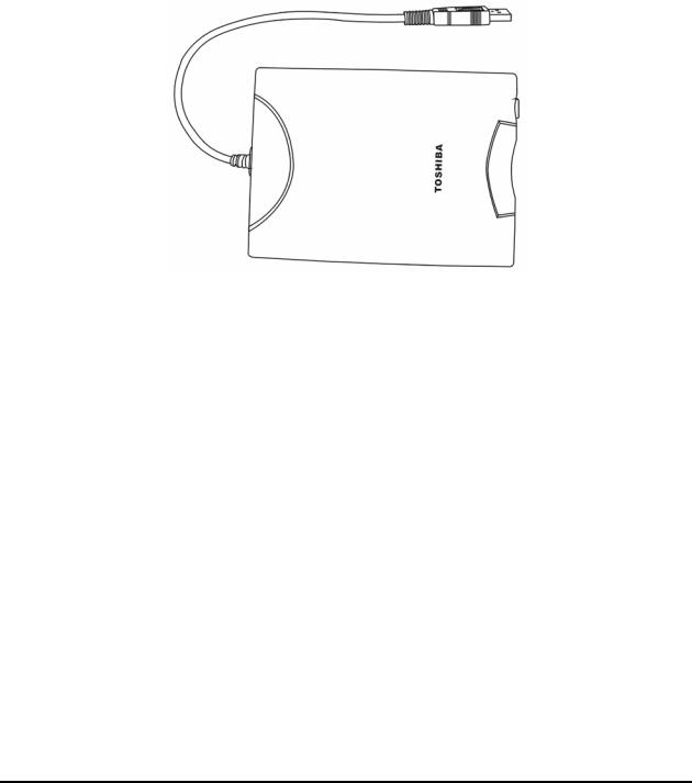
The 3.5-inch FDD is a thin, high-performance reliable drive that supports 720KB (formatted) 2DD and 1.44MB (formatted) 2HD disks.
The FDD is shown in Figure 1-1. The specifications for the FDD are listed in Table 1-1.
Figure 1-1 3.5-inch FDD
Item |
2MB mode |
1MB mode |
|
|
|
Storage capacity (KB) |
|
|
Unformatted |
2,000 |
1,000 |
Formatted |
1,440 |
720 |
|
|
|
Number of heads |
2 |
2 |
|
|
|
Number of cylinders |
80 |
80 |
|
|
|
Recording method |
Modified Frequency Modulation (MFM) |
|
|
|
|
Table 1-1 3.5-inch FDD specifications
1-8 |
Satellite A30 Series Maintenance Manual |
1.4 2.5-inch Hard Disk Drive |
1 Hardware Overview |
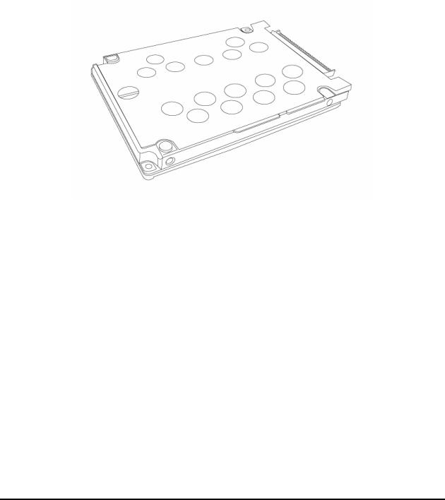
1.42.5-inch Hard Disk Drive
The removable HDD is a random access non-volatile storage device. It has a non-removable 2.5- inch magnetic disk and mini-Winchester type magnetic heads. The computer supports a 30, 40 or 60GB HDD.
The HDD is shown in Figure 1-2. Specifications are listed in Table 1-2.
Figure 1-2 2.5-inch HDD
|
Toshiba |
Toshiba |
Toshiba |
Items |
MK3021GAS |
MK4021GAS |
MK6021GAS |
(30GB) |
(40GB) |
(60GB) |
|
|
|
|
|
Formatted capacity (GB) |
27.94 |
37.26 |
55.89 |
|
|
|
|
Logical Blocks(LBA) |
58,605,120 |
78,125,000 |
117,187,500 |
|
|
|
|
Rotational speed (rpm) |
4,200 |
4,200 |
4,200 |
|
|
|
|
Buffer (MB) |
2 |
2 |
2 |
|
|
|
|
Bytes per sector |
512 |
512 |
512 |
|
|
|
|
Table 1-2 2.5-inch HDD specifications
Satellite A30 Series Maintenance Manual |
1-9 |
1 Hardware Overview |
1.5 DVD-R/-RW/-RAM Drive |
1.5DVD-R/RW/RAM Drive
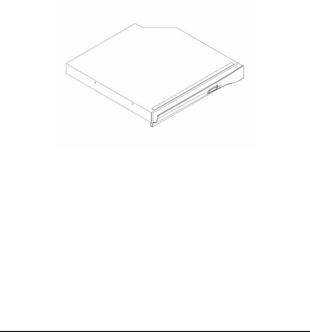
Matsushita CD-RW/DVD-ROM UJDA740, DVD-RAM UJ-810, DVD-ROM SR-8177 and TOSHIBA CD-RW/DVD SD-R2212, DVD-R/-RW SD-R6012 accommodates either 12cm (4.72-inch) or 8cm (3.15-inch) CDs or DVDs. It provides maximum eight-speed play: reads 10,820KB per second on a maximum DVD-ROM mode play and 3,600KB per second on a maximum CD-ROM mode play.
The optical media drive is shown in Figure 1-3. Specifications for the TOSHIBA DVD-R/-RW SD-R6012 drive are described in table 1-3.
|
Figure 1-3 DVD-R/RW/RAM drive |
|
|
Read Speed: |
8x DVD-ROM; 24x CD-ROM |
Write Speed: |
16x CD-R; 4x CD-RW; 8x High Speed; 1x DVD-R; 1x DVD-RW; 2x DVD- |
|
RAM |
Power Supply: |
Single +5V |
Audio: |
Output Level: 0.7 +/- 0.15 Vrms |
|
Frequency: 20 HZ – 20 kHz +/- 3 dB |
|
S/N Ratio: >= 80 dB (1 kHz, EIAJ) |
|
Distortion: <= 0.1% (1 kHz, EIAJ) |
|
Channel Separation: >= 65 dB (1 kHz, EIAJ) |
Power Supply: |
Operating Voltage: DC 5 V +/- 0.25V |
|
Power Consumption: Peak 1800 mA (max.), Read (CD) 1100 mA (typ.), |
|
Read (DVD) 950 mA (typ.), Write 1000 mA (typ.), Standby 100 mA (typ.) |
|
Ripple: 100 mVp-p max. |
ATAPI Interface: |
PIO Mode: 16.6 MB/s (PIO mode4) |
|
DMA Mode: 16.6 MB/s (Multi-word mode2) |
|
Ultra DMA Mode: 33.3 MB/s (Ultra DMA mode2) |
Access Time: |
DVD-ROM 180 ms typ. (1/3 stroke); CD-ROM 130 ms typ. (1/3 stroke) |
Start Up/Stop Time: |
15s/6s |
Table 1-3 DVD-ROM drive specifications
1-10 |
Satellite A30 Series Maintenance Manual |

1.6 Power Supply |
1 Hardware Overview |
1.6Power Supply
The power supply supplies seven different voltages to the system board and performs the following functions:
1.A/D conversion
The EC uses 10-bit sampling for A/D conversion to determine the following values:
•AC adaptor current
•Battery and temperature
2.AC adaptor and battery check
The EC checks the following by A/D converted values:
•Battery installed
The EC checks the following by GPIO values:
•AC adaptor connected
3.Abnormal check
The EC determines whether the condition is abnormal, and if so, stores an error code into the error register.
4.Input port management
The EC monitors the following input signal status:
•System power ON/OFF status
•Direct CD power ON/OFF status
5.Beep and LED control
Beep is caused by the low battery status.
The EC controls the following two kinds of LED DC IN LED (one color: green)
•Green = indicates AC adaptor is connected
Battery LED (two colors: orange and green)
•Green solid = The battery is fully charged.
Satellite A30 Series Maintenance Manual |
1-11 |

1 Hardware Overview |
1.6 Power Supply |
•Orange = The computer is quick-charging the battery / The battery is low.
6.Power ON/OFF sequence
When power is turned on or off, the EC starts the power on or off sequence.
•SQ0-4 = power ON sequence
•SQ5-B = power OFF sequence
7.Battery charging control
The EC controls the following.
•The quick charging ON/OFF
•The detection of full charge
8.Detection of the low battery
The EC detects the low battery point by the gas gauge.
•LB10M= The system will be driven by the battery for 12 more minutes.
• |
LB0 |
= The battery won't be able to drive the system after 3 minutes. |
• |
LB1 |
= The battery can drive the system only during the suspend process. |
• |
LB2 |
= The battery cannot drive the system. |
9.New battery installation
When a new battery is installed, the EC communicates with the E2PROM in the battery to read information of the newly installed battery.
10.Battery capacity calculation
The EC reads battery remaining and percentage capacity from the battery through SMBus.
1-12 |
Satellite A30 Series Maintenance Manual |

1.7 Batteries |
1 Hardware Overview |
1.7Batteries
The computer has two types of batteries:
Main battery pack
RTC battery
The removable main battery pack is the computer’s main power source when the AC adaptor is not attached.
The battery specifications are listed in Table 1-4.
Battery name |
Material |
Output voltage |
Capacity |
|
|
|
|
Main battery |
Lithium-Ion |
14.8 V |
6,450 mAh |
|
|
|
|
RTC battery |
Lithium |
3.0 V |
14 mAh |
|
|
|
|
Table 1-4 Battery specifications
Satellite A30 Series Maintenance Manual |
1-13 |

1 Hardware Overview |
1.7 Batteries |
1.7.1 Main Battery
Battery charging is controlled by a power supply microprocessor that is mounted on the system board. The power supply microprocessor controls whether the charge is on or off and detects a full charge when the AC adaptor and battery are attached to the computer. The system charges the battery using quick charge or trickle charge.
Quick Battery Charge
When the AC adaptor is attached, there are two types of quick charge: quick charge when the system is powered off and normal charge when the system is powered on.
The time required for quick charges is listed in Table 1-5.
Status |
Charging time |
|
|
Normal charge (power on) |
8 hours or longer |
|
|
Quick charge (power off) |
About 4 hours |
|
|
Table 1-5 Time required for quick charges
NOTES
1.The time required for normal charge is affected by the amount of power the system is consuming. Use of the fluorescent lamp and frequent disk access diverts power and lengthens the charge time.
2.Using quick charge, the power supply microprocessor automatically stops the charge after eight hours regardless of the condition of the battery. Overcharging could cause the battery to explode.
If any of the following occurs, the battery quick charge process stops.
1.The battery becomes fully charged.
2.The AC adaptor or battery is removed.
3.The battery or output voltage is abnormal.
4.The battery temperature is abnormal.
5.The battery SMBus communication fails.
6.The battery cell is bad.
1-14 |
Satellite A30 Series Maintenance Manual |

1.7 Batteries |
1 Hardware Overview |
Detection of full charge
A full charge is detected from the battery pack through SMBus when the battery is charging.
1.7.2 RTC battery
The RTC battery provides power to keep the current date, time and other setup information in memory while the computer is turned off. Table 1-6 lists the charging time and data preservation period of the RTC battery. The RTC battery is charged by the adaptor or main battery, while the computer is powered on.
Status |
Time |
|
|
Charging Time (power on) |
About 48 hours |
|
|
Data preservation period (full charge) |
2 month |
|
|
Table 1-6 RTC battery charging/data preservation time
Satellite A30 Series Maintenance Manual |
1-15 |

Chapter 2
Troubleshooting Procedures
 Loading...