


Toshiba Personal Computer
Satellite & Satellite Pro
Maintenance Manual
TOSHIBA CORPORATION

Copyright
© 2010 by Toshiba Corporation. All rights reserved. Under the copyright laws, this manual cannot be reproduced in any form without the prior written permission of Toshiba. No patent liability is assumed with respect to the use of the information contained herein.
Toshiba Personal Computer Satellite Maintenance Manual
First edition April.2010
Disclaimer
The information presented in this manual has been reviewed and validated for accuracy. The included set of instructions and descriptions are accurate for the Satellite Series at the time of this manual's production. However, succeeding computers and manuals are subject to change without notice. Therefore, Toshiba assumes no liability for damages incurred directly or indirectly from errors, omissions, or discrepancies between any succeeding product and this manual.
Trademarks
IBM is a registered trademark, and OS/2 and PS/2 are trademarks of IBM Corporation.
Microsoft, MS-DOS, Windows, DirectSound and DirectMusic are registered trademarks of Microsoft Corporation.
Intel and Pentium are registered trademarks, and SpeedStep is a trademark of Intel Corporation. Sound Blaster is a registered trademark of Creative Technology Ltd.
Centronics is a registered trademark of Centronics Data Computer Corporation. Photo CD is a trademark of Eastman Kodak.
All other properties are trademarks or registered trademarks of their respective holders.
Satellite A660/ProA660 Series Maintenance Manual |
ii |
Preface
This maintenance manual describes how to perform hardware service maintenance for the Toshiba Personal Computer Satellite, referred to as the Satellite Series in this manual.
The procedures described in this manual are intended to help service technicians isolate faulty Field Replaceable Units (FRUs) and replace them in the field.
SAFETY PRECAUTIONS
Four types of messages are used in this manual to bring important information to your attention. Each of these messages will be italicized and identified as shown below.
DANGER: “Danger” indicates the existence of a hazard that could result in death or serious bodily injury if the safety instruction is not observed.
WARNING: “Warning” indicates the existence of a hazard that could result in bodily injury if the safety instruction is not observed.
CAUTION: “Caution” indicates the existence of a hazard that could result in property damage if the safety instruction is not observed.
NOTE: “Note” contains general information that relates to your safe maintenance service.
Improper repair of the computer may result in safety hazards. Toshiba requires service technicians and authorized dealers or service providers to ensure the following safety precautions are adhered to strictly.
Be sure to fasten screws securely with the right screwdriver. If a screw is not fully fastened, it could come loose, creating a danger of a short circuit, which could cause overheating, smoke or fire.
If you replace the battery pack or RTC battery, be sure to use only the same model battery or an equivalent battery recommended by Toshiba. Installation of the wrong battery can cause the battery to explode.
Satellite A660/ProA660 Series Maintenance Manual |
iii |

The manual is divided into the following parts:
Chapter 1 Hardware Overview describes the Satellite Series system unit and each FRU.
Chapter 2 Troubleshooting Procedures explains how to diagnose and resolve FRU problems.
Chapter 3 Test and Diagnostics describes how to perform test and diagnostic operations for maintenance service.
Chapter 4 Replacement Procedures describes the removal and replacement of the FRUs.
Appendices The appendices describe the following:
Handling the LCD module
Board layout
Pin assignments
Keyboard scan/character codes
Key layout
Screw torque list
Reliability
Conventions
This manual uses the following formats to describe, identify, and highlight terms and operating procedures.
Acronyms
On the first appearance and whenever necessary for clarification, acronyms are enclosed in parentheses following their definition. For example:
Read Only Memory (ROM)
Keys
Keys are used in the text to describe many operations. The key top symbol as it appears on the keyboard is printed in boldface type.
Key operation
Satellite A660/ProA660 Series Maintenance Manual |
iv |

Some operations require you to simultaneously use two or more keys. We identify such operations by the key top symbols separated by a plus (+) sign. For example, Ctrl + Pause (Break) means you must hold down Ctrl and at the same time press Pause (Break). If three keys are used, hold down the first two and at the same time press the third.
User input
Text that you are instructed to type in is shown in the boldface type below:
DISKCOPY A: B:
The display
Text generated by the computer that appears on its display is presented in the typeface below:
Format complete
System transferred
Satellite A660/ProA660 Series Maintenance Manual |
v |

Table of Contents
Chapter 1 |
Hardware Overview |
|
|
1.1 |
Features ............................................................................................................................... |
1-1 |
|
1.2 |
2.5-inch HDD...................................................................................................................... |
1-9 |
|
1.3 |
DVD Super Multi (+-R Double Layer) ............................................................................. |
1-10 |
|
1.4 |
Power Supply .................................................................................................................... |
1-11 |
|
1.5 |
Batteries ............................................................................................................................ |
1-13 |
|
|
1.5.1 |
Main Battery ....................................................................................................... |
1-13 |
|
1.5.2 |
Battery Charging Control .................................................................................... |
1-13 |
|
1.5.3 |
RTC Battery ........................................................................................................ |
1-14 |
Chapter 2 Troubleshooting Procedures
2.1 |
Troubleshooting Introduction................................................................................................. |
3 |
2.2 |
Troubleshooting Flowchart .................................................................................................... |
4 |
2.3 |
Power Supply Troubleshooting............................................................................................. |
.9 |
2.4 |
Display Troubleshooting ......................................................................................... |
……….14 |
2.5 |
Keyboard Troubleshooting................................................................................................... |
17 |
2.6 |
External USB Devices Troubleshooting .............................................................................. |
19 |
2.7 |
TouchPad Troubleshooting .................................................................................................. |
22 |
2.8 |
Speaker Troubleshooting ..................................................................................................... |
24 |
2.9 |
Wireless LAN Troubleshooting ........................................................................................... |
26 |
2.10 |
Camera troubleshooting ......................... |
…………………………………………………..28 |
2.11 |
Bluetooth Troubleshooting .................................................................................................. |
30 |
2.12 |
3 in 1 card Troubleshooting ................................................................................................. |
32 |
2-13 |
HDD/SSD troubleshooting process ..................................................................................... |
34 |
2-14 |
CRT failure troubleshooting process ................................................................................... |
36 |
2-15 |
LAN Troubleshooting .......................................................................................................... |
38 |
2-16 |
MIC troubleshooting process ............................................................................................... |
40 |
|
|
|
Satellite A660/ProA660 Series Maintenance Manual |
vi |
|

2-17 |
BUTTON troubleshooting process....................................................................................... |
41 |
2.18 |
Modem troubleshooting process .......................................................................................... |
44 |
2.19 |
Express card troubleshooting process .................................................................................. |
46 |
2.20 |
HDMI troubleshooting process ............................................................................................ |
48 |
2.21 |
E-SATA troubleshooting process ........................................................................................ |
50 |
2.22 |
Optical Drive Troubleshooting ............................................................................................ |
52 |
Chapter 3 Tests and Diagnostics |
|
|
3.1 |
The Diagnostic Test ............................................................................................................... |
3 |
3.2 |
Executing the Diagnostic Test ............................................................................................... |
4 |
3.3 |
Display Configuration ........................................................................................................... |
8 |
3.4 |
Audio sound Test ................................................................................................................... |
9 |
3.5 |
Fan ON/OFF Test................................................................................................................... |
9 |
3.6 |
Main Battery Charge Test .................................................................................................... |
11 |
3.7 |
FDD Test .......................................................................................................................... |
…11 |
3.8 |
Memory Check ..................................................................................................................... |
14 |
3.9 |
Keyboard Test ...................................................................................................................... |
14 |
3.10 |
Mouse (Pad) Test ................................................................................................................. |
16 |
3.11 |
LCD Pixels Mode Test......................................................................................................... |
17 |
3.12 |
Magnetic switch Test ........................................................................................................... |
18 |
3.13 |
LAN Test.............................................................................................................................. |
20 |
3.14 |
RTC Test .............................................................................................................................. |
23 |
3.15 |
BUTTON Test...................................................................................................................... |
24 |
3.16 |
1st HDDTest......................................................................................................................... |
26 |
3.17 |
RDMI Test ........................................................................................................................... |
27 |
3.18 |
WDMI Test .......................................................................................................................... |
28 |
Satellite A660/ProA660 Series Maintenance Manual |
vii |

Chapter 4 Replacement Procedures |
|
|
4.1 |
General ............................................................................................................................. |
4-1 |
|
Safety Precautions ............................................................................................................ |
4-3 |
|
Before You Begin............................................................................................................. |
4-5 |
|
Disassembly Procedures................................................................................................... |
4-6 |
|
Assembly Procedures ....................................................................................................... |
4-6 |
|
Tools and Equipment ....................................................................................................... |
4-7 |
|
Screw Tightening Torque................................................................................................. |
4-7 |
|
Colors of Screw Shanks ................................................................................................... |
4-8 |
|
Symbols of Screws on the Laptop Body .......................................................................... |
4-8 |
|
Symbol examples ............................................................................................................. |
4-8 |
4.2 |
Battery.............................................................................................................................. |
4-9 |
|
Removing the Battery Pack .............................................................................................. |
4-9 |
|
Installing the Battery Pack.............................................................................................. |
4-10 |
4.3 |
HDD............................................................................................................................... |
4-11 |
|
Removing the HDD........................................................................................................ |
4-11 |
|
Installing the HDD ......................................................................................................... |
4-13 |
4.4 |
Memory.......................................................................................................................... |
4-15 |
|
Removing the Optional Memory.................................................................................... |
4-15 |
|
Installing the Optional Memory ..................................................................................... |
4-16 |
4.5 |
Keyboard ........................................................................................................................ |
4-17 |
|
Removing the Keyboard................................................................................................. |
4-17 |
|
Installing the Keyboard .................................................................................................. |
4-19 |
4.6 |
TV Tuner Card and WLAN Card .................................................................................. |
4-20 |
|
Removing the TV Tuner Card........................................................................................ |
4-20 |
|
Removing the WLAN Card............................................................................................ |
4-21 |
|
Installing the TV Tuner Card ......................................................................................... |
4-21 |
|
Installing the WLAN Card ............................................................................................. |
4-22 |
4.7 |
ODD............................................................................................................................... |
4-23 |
|
Removing the ODD Bay Module ................................................................................... |
4-23 |
|
Installing the ODD Bay Module..................................................................................... |
4-24 |
Satellite A660/ProA660 Series Maintenance Manual |
viii |
|
Disassembling the ODD Drive....................................................................................... |
4-24 |
|
Assembling the ODD Drive ........................................................................................... |
4-25 |
4.8 |
Logic Upper Assembly .................................................................................................. |
4-26 |
|
Removing the Logic Upper Assembly ........................................................................... |
4-26 |
|
Installing the Logic Upper Assembly............................................................................. |
4-28 |
4.9 |
ODD module (Slot-load)................................................................................................ |
4-29 |
|
Removing the ODD Module (Slot-Load)....................................................................... |
4-29 |
|
Installing the ODD Module (Slot-Load) ........................................................................ |
4-29 |
|
Disassembling the ODD (Slot-load) .............................................................................. |
4-30 |
|
Assembling the ODD (Slot-load) ................................................................................... |
4-31 |
4.10 |
FeliCa Card .................................................................................................................... |
4-32 |
|
Removing the FeliCa Card ............................................................................................. |
4-32 |
|
Installing the FeliCa Card............................................................................................... |
4-32 |
4.11 |
Fingerprint Scanner Bracket .......................................................................................... |
4-33 |
|
Removing the Fingerprint Scanner Bracket ................................................................... |
4-33 |
|
Installing the Fingerprint Scanner Bracket ..................................................................... |
4-35 |
4.12 |
Touch Pad Board............................................................................................................ |
4-36 |
|
Removing the Touch Pad Board .................................................................................... |
4-36 |
|
Installing the Touch Pad Board ...................................................................................... |
4-36 |
4.13 |
Speakers and Speaker Cushions..................................................................................... |
4-37 |
|
Removing the Speakers .................................................................................................. |
4-37 |
|
Removing the Speaker Cushions.................................................................................... |
4-38 |
|
Installing the Speaker Cushions ..................................................................................... |
4-38 |
|
Installing the Speakers.................................................................................................... |
4-38 |
4.14 |
Indicator Board .............................................................................................................. |
4-39 |
|
Removing the Indicator Board ....................................................................................... |
4-39 |
|
Installing the Indicator Board ......................................................................................... |
4-39 |
4.15 |
USB Board ..................................................................................................................... |
4-40 |
|
Removing the USB Board.............................................................................................. |
4-40 |
|
Installing the USB Board ............................................................................................... |
4-40 |
4.16 |
Bluetooth........................................................................................................................ |
4-41 |
|
Removing the Bluetooth................................................................................................. |
4-41 |
|
|
|
Satellite A660/ProA660 Series Maintenance Manual |
ix |
|
|
Installing the Bluetooth .................................................................................................. |
4-41 |
4.17 |
Thermal Fan ................................................................................................................... |
4-42 |
|
Removing the Thermal Fan............................................................................................ |
4-42 |
|
Installing the Thermal Fan ............................................................................................. |
4-42 |
4.18 |
TV Tuner Antenna ......................................................................................................... |
4-43 |
|
Removing the TV Tuner Antenna .................................................................................. |
4-43 |
|
Installing the TV Tuner Antenna.................................................................................... |
4-43 |
4.19 |
Power Membrane ........................................................................................................... |
4-44 |
|
Removing the Power Membrane.................................................................................... |
4-44 |
|
Installing the Power Membrane ..................................................................................... |
4-44 |
4.20 |
Display Assembly .......................................................................................................... |
4-45 |
|
Removing the Display Assembly ................................................................................... |
4-45 |
|
Installing the Display Assembly..................................................................................... |
4-46 |
|
Removing the Motherboard Assembly........................................................................... |
4-47 |
|
Installing the Motherboard ............................................................................................. |
4-48 |
4.21 |
Thermal Module ............................................................................................................ |
4-49 |
|
Removing the Thermal Module ..................................................................................... |
4-49 |
|
Installing the Thermal Module ....................................................................................... |
4-51 |
4.22 |
CPU................................................................................................................................ |
4-54 |
|
Removing the CPU ........................................................................................................ |
4-54 |
|
Installing the CPU .......................................................................................................... |
4-55 |
4.23 |
LCD Bezel ..................................................................................................................... |
4-56 |
|
Removing the LCD Bezel .............................................................................................. |
4-56 |
|
Installing the LCD Bezel ................................................................................................ |
4-58 |
4.24 |
LCD Panel...................................................................................................................... |
4-59 |
|
Removing the LCD Panel .............................................................................................. |
4-59 |
|
Installing the LCD Panel ................................................................................................ |
4-60 |
4.25 |
Web Camera .................................................................................................................. |
4-61 |
|
Removing the Web Camera ........................................................................................... |
4-61 |
|
Installing the Web Camera ............................................................................................. |
4-61 |
4.26 |
WLAN Antennas ........................................................................................................... |
4-62 |
|
Removing the WLAN Antennas .................................................................................... |
4-62 |
|
|
|
Satellite A660/ProA660 Series Maintenance Manual |
x |
|
|
Installing the WLAN Antennas ...................................................................................... |
4-63 |
4.27 |
LCD Panel Hinges ......................................................................................................... |
4-64 |
|
Removing the LCD Panel Hinges .................................................................................. |
4-64 |
|
Installing the LCD Panel Hinges .................................................................................... |
4-64 |
4.28 |
LVDS Cable ................................................................................................................... |
4-65 |
|
Removing the LVDS Cable............................................................................................ |
4-65 |
|
Installing the LVDS Cable ............................................................................................. |
4-65 |
Figures |
|
Figures |
|
Figure 4.1 Removing the Battery Pack .................................................................................. |
4-9 |
Figure 4.2 Removing the HDD door.................................................................................... |
4-11 |
Figure 4.3 Releasing the HDD from the connector.............................................................. |
4-12 |
Figure 4.4 Removing the HDD from the HDD bay ............................................................. |
4-12 |
Figure 4.5 Removing the HDD foil ..................................................................................... |
4-13 |
Figure 4.6 Securing the HDD foil ........................................................................................ |
4-14 |
Figure 4.7 Removing the RAM door ................................................................................... |
4-15 |
Figure 4.8 Removing the RAM from the connectors........................................................... |
4-16 |
Figure 4.9 Removing the keyboard ...................................................................................... |
4-17 |
Figure 4.10 Releasing the keyboard..................................................................................... |
4-18 |
Figure 4.11 Raising the keyboard ........................................................................................ |
4-18 |
Figure 4.12 Disconnecting the cables and removing the keyboard...................................... |
4-19 |
Figure 4.13 Removing the TV tuner card ............................................................................ |
4-20 |
Figure 4.14 Removing the WLAN Card .............................................................................. |
4-21 |
Figure 4.15 Removing the ODD bay module ...................................................................... |
4-23 |
Figure 4.16 Removing the ODD bracket from the ODD drive............................................ |
4-24 |
Figure 4.17 Removing the ODD bezel from the ODD drive ............................................... |
4-25 |
Figure 4.18 Removing thirteen screws from the bottom of the laptop ................................ |
4-26 |
Figure 4.19 Disconnecting the cables and removing the upper logic assembly screw ........ |
4-27 |
Figure 4.20 Removing the logic upper assembly................................................................. |
4-27 |
Figure 4.21 Disassembling the Slot-load ODD ................................................................... |
4-30 |
|
|
Satellite A660/ProA660 Series Maintenance Manual |
xi |

Figure 4.22 Removing the FeliCa card from the logic upper assembly............................... |
|
4-32 |
Figure 4.23 Raising the fingerprint scanner bracket from the logic upper assembly........... |
4-33 |
|
Figure 4.24 Working the fingerprint scanner bracket loose................................................. |
|
4-34 |
Figure 4.25 Removing the fingerprint scanner bracket from the logic upper assembly ...... |
4-34 |
|
Figure 4.26 Removing the touch pad board......................................................................... |
|
4-36 |
Figure 4.27 Removing the speakers..................................................................................... |
|
4-37 |
Figure 4.28 Removing the speaker cushions ....................................................................... |
|
4-38 |
Figure 4.29 Removing the indicator board .......................................................................... |
|
4-39 |
Figure 4.30 Removing the USB board................................................................................. |
|
4-40 |
Figure 4.31 Removing the Bluetooth................................................................................... |
|
4-41 |
Figure 4.32 Removing the thermal fan ................................................................................ |
|
4-42 |
Figure 4.33 Removing the TV tuner antenna....................................................................... |
|
4-43 |
Figure 4.34 Removing the power membrane....................................................................... |
|
4-44 |
Figure 4.35 Removing the display assembly ....................................................................... |
|
4-45 |
Figure 4.36 Removing the DC in cable from the connector slot ......................................... |
|
4-47 |
Figure 4.37 Removing the discreet motherboard from the system ...................................... |
|
4-48 |
Figure 4.38 Removing the thermal module (Discrete model) ............................................. |
|
4-49 |
Figure 4.39 Removing the thermal module (UMA model) ................................................. |
|
4-50 |
Figure 4.40 Reapplying Shinetsu 7762 grease on the thermal module |
and remove any release |
|
papers ........................................................................................................... |
|
4-51 |
Figure 4.41 Installing the thermal module (Discrete model) ............................................... |
|
4-52 |
Figure 4.42 Reapplying Shinetsu 7762 grease on the thermal module |
and remove any release |
|
papers ........................................................................................................... |
|
4-52 |
Figure 4.43 Installing the thermal module (UMA model) ................................................... |
|
4-53 |
Figure 4.44 Removing the CPU........................................................................................... |
|
4-54 |
Figure 4.45 Removing four screws securing the LCD bezel to the display assembly ......... |
4-56 |
|
Figure 4.46 Prying up the LCD bezel from the outside edges ............................................. |
|
4-57 |
Figure 4.47 Removing the LCD panel from the display assembly ...................................... |
|
4-59 |
Figure 4.48 Disconnecting the Webcam .............................................................................. |
|
4-60 |
Figure 4.49 Removing the web camera from the display assembly..................................... |
|
4-61 |
Figure 4.50 Removing the WLAN antennas from the display assembly............................. |
4-62 |
|
Figure 4.51 Routing the WLAN antennas onto the display assembly ................................. |
|
4-63 |
Satellite A660/ProA660 Series Maintenance Manual |
xii |

Figure 4.52 |
Removing the LCD panel hinges from the LCD Panel .................................... |
4-64 |
Figure 4.53 |
Removing the LVDS cable from the LCD panel.............................................. |
4-65 |
Appendices |
|
|
Appendix A |
Handling the LCD Module ................................................................................... |
A-1 |
Appendix B |
Board Layout......................................................................................................... |
B-1 |
Appendix C |
Pin Assignments.................................................................................................... |
C-1 |
Appendix D |
Keyboard Scan/Character Codes........................................................................... |
D-1 |
Appendix E |
Key Layout ............................................................................................................ |
E-1 |
Appendix F |
Series Screw Torque List ....................................................................................... |
F-1 |
Appendix G |
Reliability.............................................................................................................. |
G-1 |
Satellite A660/ProA660 Series Maintenance Manual |
xiii |

1 Hardware Overview
Chapter 1
Hardware Overview
Satellite A660/Pro A660 Maintenance Manual |
1-i |

1 Hardware Overview
Chapter 1 |
Contents |
|
|
1.1 |
Features |
.................................................................................................................. |
1-1 |
1.2 |
2.5-inch .......................................................................................................HDD |
1-11 |
|
1.3 |
DVD Super ................................................................Multi (+-R Double Layer) |
1-12 |
|
1.4 |
BD-RE and .............................................................................BD-Combo drives |
1-13 |
|
1.5 |
Power Supply ....................................................................................................... |
1-14 |
|
1.6 |
Batteries................................................................................................................ |
|
1-16 |
|
1.6.1 ......................................................................................... |
Main Battery |
1-16 |
|
1.6.2 ...................................................................... |
Battery Charging Control |
1-16 |
|
1.6.3 .......................................................................................... |
RTC Battery |
1-17 |
Satellite A660/Pro A660 Maintenance Manual |
1-ii |

1 Hardware Overview
Figures |
|
|
Figure 1-1A |
ID Parts Description Placement Part A.......................................................... |
1-6 |
Figure 1-2 |
SATA HDD ................................................................................................. |
1-11 |
Figure 1-3 |
DVD Super Multi Drive............................................................................... |
1-12 |
Figure 1-4 |
BD-RE or BD-Combo drive (depending on the model) .............................. |
1-13 |
Tables |
|
|
Table 1-1 |
HDD Specifications ..................................................................................... |
1-11 |
Table 1-2 |
DVD Super Multi Drive Specifications ....................................................... |
1-12 |
Table 1-3 |
Blu-ray Disc Drive specifications ................................................................ |
1-13 |
Table 1-4 |
Quick/Normal Charging Time ..................................................................... |
1-16 |
Satellite A660/Pro A660 Maintenance Manual |
1-iii |

1 Hardware Overview
1.1Features
The Toshiba Satellite A660/A665/A667 Series and Dynabook TX/AX Series is a full-size PC notebook based on a Dual Core/Quad Core Processor, providing high-speed processing capabilities and advanced features. The computer employs a lithium ion battery that allows it to operate without a DC-in connection for extended periods of time. The display uses a 15.6” or 16” TFT LCD panel. The PGA socket supports BTO for the CPU so that the system can be designed to suit the customer’s needs.
The computer has the following features:
Processor (BTO)
The computer is equipped with one of the following Intel® processors.
Intel® Clarksfield Processor Support
Intel® Arrandale Processor
Memory (BTO)
The computer has two SODIMM slots that come standard with 1GB, 2GB or 4GB BTO to meet various memory requirements. It can incorporate up to 8 GB of main memory. It supports DDR3 at 800MHz/1066MHz. or 1333MHz depending on the CPU.
Battery Pack
The computer is powered by one rechargeable and removable lithium ion battery pack. The capacity is either 3-cell, 6-cell or 12-cell, depending on the model of the computer.
Hard Disk Drive (HDD) (BTO)
The computer accommodates one 9.5 mm HDD with the following storage options:
160/250/320/500/640GB SATA (5,400rpm)
320/500GB SATA (7,200rpm)
64GB/128/256/512GB TOSHIBA solid-state drive (SSD)
ODD (BTO)
12.7mm height DVD Super Multi drive (supporting DVD-R / -RW / +R / +RW / -RAM / -RDL / +RDL / CD-R / CD-RW) Double Layer with Labelflash
Satellite A660/Pro A660 Maintenance Manual |
1-1 |

1 Hardware Overview
12.7mm height BD-Combo drive (supporting BD/DVD/CD/ DVD-R / -RW / +R / +RW
/-RAM / -RDL / +RDL / CD-R / CD-RW)
12.7mm height BD-RE drive (supporting BD/DVD/CD/BD-R/BD-RE/ DVD-R / -RW / +R / +RW / -RAM / -RDL / +RDL / CD-R / CD-RW)
Display (BTO)
The computer display features one of the following LCD panels:
16"W 1366 x 768: color TFT/HD
15.6"W 1366 x 768: color TFT/HD
Graphics (BTO)
Intel Arrandale for int. Gfx
Nvidia N11M-GE1, N11P-GE1, N11E-GE1-LP, N11M-OP1 ( DDR3, 512/1024MB)
Keyboard (BTO)
The computer is equipped with an illuminated Toshiba 2010 A4 keyboard with 102 keys, including number pad. It is a Win7 compliant keyboard featuring a Windows key and application keys.
Pointing Device
The integrated Wide Touch Pad and two control buttons in the palm rest allow for control of the on-screen pointer and supports functions such as multi-touch touchpad gestures and window scrolling. The device also features a touchpad on/off button and an LED light bar.
External Monitor Port (BTO)
The analog VGA port provides support for VESA DDC2B compatible functions. A WDDM driver is ready for Windows 7.
Satellite A660/Pro A660 Maintenance Manual |
1-2 |

1 Hardware Overview
Universal Serial Bus (USB) Ports
The computer has three USB 2.0 ports. It is supported to daisy-chain a maximum of 127 USB devices. The serial data transfer rate is 480 Mbps or 12 Mbps and 1.5 Mbps. These ports support PnP installation and hot plugging. They also support Sleep and Charge function.
eSATA/USB Combo Port
The external eSATA/USB combo port executes high-speed data transfers to external devices and now supports shielded cable lengths of up to 2 meters outside the computer. The port also complies with the USB 2.0 standard
Express Card Slot
The internal Express Card slot is a universal slot. This slot supports ExpressCard34/54 and the slot is covered with a dummy card. It also supports USB/PCI Express signals.
Bridge Media Slot
This slot allows you to insert SD, MiniSD/ MicroSD (through adapter), Memory Stick/Memory Stick Duo (through adaptor), Memory Stick Pro/Memory Stick Duo (through adaptor), xD and MMC memory cards. It supports High-speed SD, SDHC and SD-IO. An I/O port heel cover is needed. This model does not support CF or Smart Media cards.
Sound system
The integrated sound system provides support for the computer’s internal speakers and microphone, also allowing an external microphone and headphones to be connected via the appropriate jacks. It is composed of two Harman/Kardon OdysseyII 10cc internal speakers and an internal microphone (equipped with echo cancellation).
Internal Camera (BTO)
Camera supports 1.3M pixels without Auto Macro and comes with a blue LED indicator. (The internal camera is BTO with the internal microphone). The camera is not a rotation type.
HDMI Out Port (BTO)
HDMI 1.3 out port can connect with Type A connector HDMI cable. One HDMI cable can send and receive SD and HD video/audio and control signals.
Satellite A660/Pro A660 Maintenance Manual |
1-3 |
1 Hardware Overview
Headphones-Out Jack
This jack enables connection of stereo headphones (16 ohm minimum). When connected to headphones, the internal speakers are automatically disabled.
Microphone/ Line-in Jack
A 3.5mm mini microphone jack enables connection of a three-conductor microphone for monaural input and also enables the connection of a stereo device for audio input.
LAN (BTO)
The computer has built-in support for Gigabit Ethernet LAN (1000 megabits per second, 1000BASE-T) and 10M/100M Ethernet LAN (10/100 megabits per second, 10/100BASE- T). It employs a Realtek 8111E for Gigabit LAN or 8105E for 10M/100Mbit LAN. It is preinstalled as a standard device in some markets.
Wireless LAN (BTO)
Some computers in this series are equipped with a Wireless LAN card. This WLAN module may come in with the following types (depending on the model):
Realtek 802.11b/g, 8191SE (1x2)
Atheros 802.11 HB95 (1x1)
PumaPeak 802.11a/b/g (2x2), a/b/g/n (2x2)
Internal Modem (BTO)
Some models are equipped with an integrated modem. The integrated modem provides capability for data and fax communications that support the V.90 (V.92) standards and includes a modem jack for connection to the telephone line. Please note that both the V.90 and V.92 standards are only supported in the USA, Canada, United Kingdom, France, Germany and Australia - only the V.90 standard is supported in other regions. You should also be aware that the speed of data and fax transfer will depend on the analog telephone line conditions. The integrated model is only installed as a standard device in some markets. This internal modem comes with MDC 1.5 solution (Azalia interface).
Felica (BTO)
Some models feature an embedded Felica module writes and reads data to and from contactless Felica IC cards. Having no need for physical contact with the card, the Reader/Writer is immune to performance deterioration caused by wear and contamination, providing easy maintenance and long-term reliability.
Satellite A660/Pro A660 Maintenance Manual |
1-4 |

1 Hardware Overview
Bluetooth (BTO)
Some computers in this series offer Bluetooth wireless communication functionality which eliminates the need for cables between electronic devices such as computers and printers. When implemented, Bluetooth provides a fast, reliable and secure means to achieve wireless communication in a small space. This module is Version 2.1 + EDR and is V3.0+HS support ready.
Fingerprint Sensor (BTO)
The computer has a fingerprint utility installed for the purpose of enrolling and recognizing fingerprints. By enrolling the ID and password to the fingerprint authentication device, it is no longer necessary to input the password from the keyboard. The Fingerprint sensor is located at the center of the Touch Pad panel and is an Authentec AES1660.
TV Tuner (BTO)
Some models are equipped with ATSC/NSTC for Express card type TV tuner and PCIE mini type for the reception and playback of DVBT.
Sound system (BTO)
The integrated sound system provides support for the computer’s internal speakers and microphone, also allowing an external microphone and headphones to be connected via the appropriate jacks. The computer has two Harman or Kardon (Odyssey2) speakers.
Satellite A660/Pro A660 Maintenance Manual |
1-5 |
1 Hardware Overview
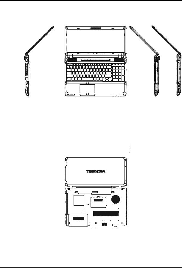
Figure 1-1A shows the computer and its system unit configuration.
Figure 1-1A ID Parts Description Placement Part A
Satellite A660/Pro A660 Maintenance Manual |
1-6 |
1 Hardware Overview
Satellite A660/Pro A660 Maintenance Manual |
1-7 |

1 Hardware Overview
Satellite A660/Pro A660 Maintenance Manual |
1-8 |

1 Hardware Overview
The system unit of the computer consists of the following components:
Processor (BTO)
The computer is equipped with one of the following Intel® processors:
Intel® Clarksfield Processor
Intel® Arrandale Processor
Memory (BTO)
The computer has two SODIMM slots that come standard with 1GB/2GB/4GB, BTO for various memory requirements. It can incorporate up to 8 GB of main memory. It supports DDR3 at 1066MHZ and 1333MHZ depending on the model.
BIOS ROM (EEPROM)
The system BIOS is one 4096KB ROM and the keyboard BIOS is one 256KB ROM, both of which are ACPI-compliant. The flash utility can be used to program both system and keyboard BIOS at the same time.
System Controllers
Advanced Power Management 1.2 support
ACPI2.0 b and PC2001 compliant
Support SMBus specification V2.0
Hot keys for system control
Audio volume output control
External LED control
Battery scope report and control
Sticky key support
Power switch control
Two host interface channels support
Supports three independent devices
Internal Keyboard country selection
Wireless LAN on/off button
Satellite A660/Pro A660 Maintenance Manual |
1-9 |

1 Hardware Overview
Graphics Controller
Intel® HM55 as integrated graphics solution
Following External Graphic solution with Intel PM55/HM55
NVIDIA® GeForce® N11M-GE1/N11P-GE1/N11E-GE1-LP, N11M-OP1
HDMI 1.3-CEC support
Express Card Controller
Support USB/PCI Express signals
One Express Card slot 34
Audio Controller
Realtek Azalia ALC269
One Audio-in port: Mic.-in/Line-in
One Audio-out port: Headphone-out / Line-out
Internal Microphone (with Internal Camera, MIC with echo cancellation)
Volume control: Digital control, feather touch button, no mute function
Microsoft inbox audio driver support
Software EQ support
Synchronize to change video and audio output to HDMI/DP
MAXX audio support by SW solution (BTO by image)
Wireless LAN Controller
Realtek 802.11b/g, 8191SE (1x2)
Atheros 802.11 HB95 (1x1)
PumaPeak 802.11a/b/g (2x2), a/b/g/n (2x2)
Satellite A660/Pro A660 Maintenance Manual |
1-10 |
1 Hardware Overview
1.22.5-inch HDD
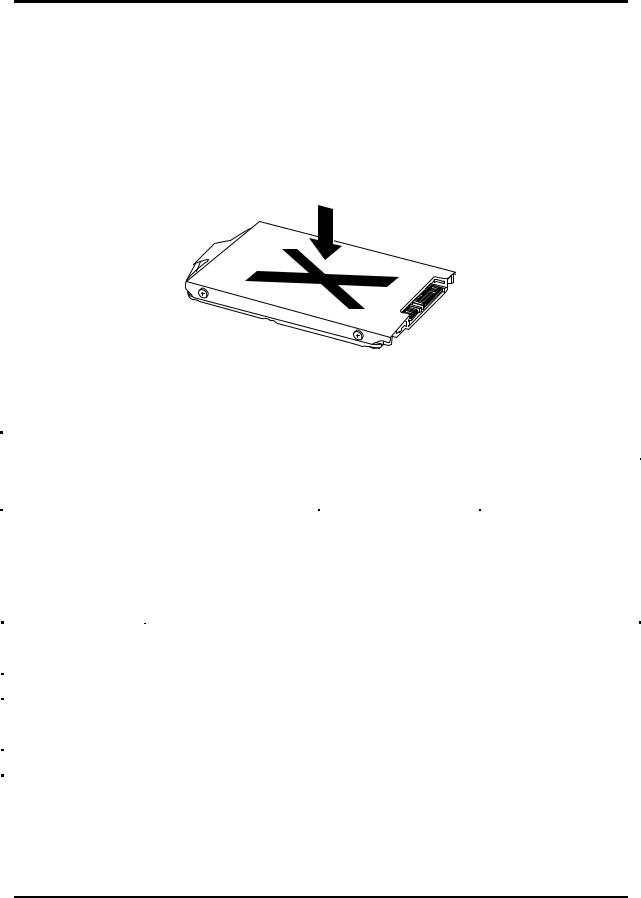
The computer contains an extremely low-profile and lightweight, high-performance HDD. The HDD incorporates 9.5 mm / 12.5 mm height magnetic disk and mini-Winchester type magnetic heads. The HDD interface conforms to Serial ATA. Storage capacities supported are 160, 250, 320, 400, 500 and 640GB.
The HDD is shown in Figure 1-2 and some of its specifications are listed in Table 1-1.
|
|
Figure 1-2 |
|
|
SATA HDD |
|
|
|
|
|
Table 1-1 |
HDD Specifications |
|
|
|||
|
|
|
|
|
|
|
|
|
Item |
|
|
|
Specifications |
|
|
||
|
|
|
|
|
|
|
|
|
Capacity (GB) |
160GB |
|
|
250G |
|
320 GB |
||
|
|
|
|
|
|
|
|
|
Rotational Speed (RPM) |
5400 RPM |
|
|
5400 or 7200 RPM |
|
5400 or 7200 RPM |
||
|
|
|
|
|
|
|
|
|
Height |
9.5 mm |
|
|
9.5 mm |
|
9.5 mm |
||
|
|
|
|
|
|
|
|
|
User Data Sectors |
312,581,808 |
|
|
488,397,168 |
|
625,142,448 |
||
|
|
|
|
|
|
|
|
|
Bytes / Sector |
512 |
|
|
512 |
|
512 |
||
|
|
|
|
|
|
|
|
|
|
|
|
|
|
|
|
|
|
Item |
|
|
|
|
Specifications |
|
|
|
|
|
|
|
|
|
|
|
|
Capacity (GB) |
|
500GB |
|
|
|
|
|
640 GB |
|
|
|
|
|
|
|
||
Rotational Speed (RPM) |
|
5400 or 7200 RPM |
|
|
|
5400 RPM |
||
|
|
|
|
|
|
|
|
|
Height |
|
9.5 mm |
|
|
|
|
|
9.5 mm |
|
|
|
|
|
|
|
|
|
User Data Sectors |
|
976,773,168 |
|
|
|
|
1,250,263,728 |
|
|
|
|
|
|
|
|
|
|
Bytes / Sector |
|
512 |
|
|
|
|
512 |
|
|
|
|
|
|
|
|
|
|
Satellite A660/Pro A660 Maintenance Manual |
1-11 |
1 Hardware Overview
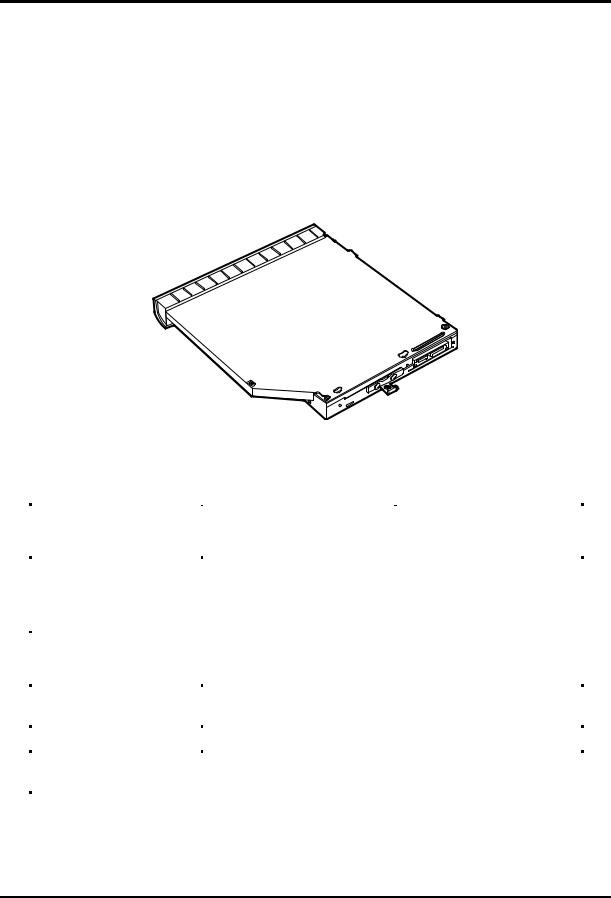
1.3DVD Super Multi (+-R Double Layer)
The DVD Super Multi drive accepts 12-cm (4.72-inch) and 8-cm (3.15-inch) discs. At maximum, the drive can play back a DVD at 8x speed, read CD-ROM at 24x speed, and write CD-R at 24x speed, CD-RW at 6x speed, CD-RW at 16x speed, DVD-R at 8x speed, DVD-RW at 8x speed, DVD+R at 8x speed, DVD+R (Double Layer) at 8x speed, DVD-R (Dual Layer) at 8x speed, DVD+RW at 8x speed and DVD-RAM at 5x speed.
The DVD Super Multi drive is shown in Figure 1-3 and its specifications are listed in Table 1-2.
Figure 1-3 DVD Super Multi Drive
Table 1-2 DVD Super Multi Drive Specifications
Item |
DVD-ROM Mode |
CD-ROM Mode |
|
|
|
|
|
|
33.3 (U-DMA transfer mode 2) |
|
|
Data Transfer Rate (Mbytes/s) |
16.6 (PIO mode 4, Multiword DMA mode 2) |
||
|
|||
|
|
|
|
Access Time (ms) |
|
|
|
Average Random Access |
130 |
130 |
|
|
|
|
|
Data Buffer Size (Mbytes) |
2MB |
|
|
|
|
|
|
|
DVD: |
|
|
|
|
||
|
|
||
|
DVD-VIDEO, DVD-ROM, DVD-R, DVD-RW, DVD-RAM, DVD+R, |
||
|
DVD+-R (Double Layer), DVD+RW. |
||
Formats Supported |
|
|
|
|
CD: |
|
|
|
|
|
|
|
|
||
|
CD-DA, CD-ROM, CD-R, CD-RW, CD-ROMXA, Photo CD |
||
|
(Multi-Session), Video CD, CD-Extra (CD+), CD-Text. |
||
|
|
|
|
Satellite A660/Pro A660 Maintenance Manual |
1-12 |
1 Hardware Overview
1.4BD-RE and BD-Combo drives
The BD-RE and BD-Combo drives accept 12-cm (4.72-inch) and 8-cm (3.15-inch) discs and can play BDs, DVDs and CDs. At maximum the drives can playback BD at 6x speed, DVD at 8x speed, read CD-ROM at 24x speed
The BD-RE and BD-Combo drives let you record data to writable CD/DVD discs. The drives can write CD-RW at 16x speed, CD-R at 24x speed, DVD-RAM at 5x speed, DVD+R DL at 4x speed, DVD-R DL at 4x speed, DVD+RW at 4x speed, DVD+R at 8x speed, DVD-RW at 6x speed, DVD-R at 8x speed.
In addition to being able to write to recordable CD/DVD discs, the BD-RE drive can write to BD-R as 6x speed, BD-R(DL) at 4x speed, BD-RE at 2x speed and BD-RE (DL) at 2x speed.
Figure 1-4 BD-RE or BD-Combo drive (depending on the model)
Table 1-3 Blu-ray Disc Drive specifications
|
Item |
|
BD-ROM Mode |
DVD-ROM Mode |
CD-ROM Mode |
|
|
|
|
|
|
|
|
|
|
|
33.3 (U-DMA transfer mode 2) |
|
|
|
|
Data Transfer Rate (Mbytes/s) |
|
16.6 (PIO mode 4, Multiword DMA mode 2) |
|
|
|
|
|
|
|
|||
|
|
|
|
|||
|
|
|
|
|
||
|
|
|
|
|
|
|
|
Access Time (ms) |
|
|
|
|
|
|
Average Random Access |
|
130 |
|
|
|
|
|
|
|
|
|
|
|
Data Buffer Size (Mbytes) |
|
2MB |
|
|
|
|
|
|
|
|
|
|
|
|
|
BD: |
|
|
|
|
|
|
|
|
|
|
|
|
|
DVD: |
|
|
|
|
|
|
DVD-VIDEO, DVD-ROM, DVD-R, DVD-RW, DVD-RAM, DVD+R, |
|
||
|
Formats Supported |
|
DVD+-R (Double Layer), DVD+RW. |
|
|
|
|
|
|
CD: |
|
|
|
|
|
|
CD-DA, CD-ROM, CD-R, CD-RW, CD-ROMXA, Photo CD |
|
||
|
|
|
(Multi-Session), Video CD, CD-Extra (CD+), CD-Text. |
|
||
|
|
|
|
|
|
|
|
|
|
|
|
|
|
Satellite A660/Pro A660 Maintenance Manual |
1-13 |
 Loading...