


INSTALLATION MANUAL
MANUAL DE INSTALACIÓN
MANUEL D’INSTALLATION MANUALE DI INSTALLAZIONE EINBAUANLEITUNG
MANUAL DE INSTALAÇÃO
ΕΓ ΕΙΡΊΔΙ ΕΓΚΑΤΆΣΤΑΣΗΣ
INSTRUKCJA INSTALACJI INSTALAČNÍ PŘÍRUČKA PRIRUČNIK ZA UGRADNJU ÜZEMBE HELYEZÉSI KÉZIKÖNYV
INSTALLATIEHANDLEIDING
AIR CONDITIONER (SPLIT TYPE)
ACONDICIONADOR DE AIRE (TIPO SPLIT)
CLIMATISEUR (SPLIT SYSTEM)
CONDIZIONATORE D’ARIA (TIPO SCOMPONIBILE)
KLIMAGERÄT (GETEILTE AUSFÜHRUNG)
AR CONDICIONADO (TIPO SPLIT)
ΚΛΙΜΑΤΙΣΤΙΚ ΜΗ ΑΝΗΜΑ (ΔΙΑΙΡ ΎΜΕΝ Σ ΤΎΠ Σ)
KLIMATYZATOR (TYPU DZIELONEGO)
KLIMATIZAČNÍ ZAŘÍZENÍ (DĚLENÝ TYP)
KLIMATSKI UREĐAJ (RASTAVLJIV MODEL)
LÉGKONDICIONÁLÓ (OSZTOTT TÍPUS)
AIR CONDITIONER (TWEEDELIG TYPE)
RAS-13GK Series |
RAS-13GA Series |
Indoor Unit |
Outdoor Unit |
Unidad Interior |
Unidad Exterior |
Unité Intérieure |
Unité Extérieure |
Unità Interna |
Unità Esterna |
Innengerät |
Außengerät |
Unidade Interior |
Unidade Exterior |
Εσωτερική Μ νάδα |
Ε#ωτερική Μ νάδα |
Urządzenie Wewnętrzne |
Urządzenie Zewnętrzne |
Vnitřní Jednotka |
Venkovní Jednotka |
Unutarnja Jedinica |
Vanjska Jedinica |
Beltéri Egység |
Kültéri Egység |
Binnenmodule |
Buitenmodule |

CONTENTS
PRECAUTIONS FOR SAFETY ...................................... |
1 |
|
INSTALLATION DIAGRAM OF INDOOR AND |
|
|
OUTDOOR UNITS .......................................................... |
2 |
|
• |
Optional Installation Parts ................................................ |
2 |
INDOOR UNIT |
|
|
• |
Installation Place ............................................................... |
3 |
• Cutting a Hole and Mounting Installation Plate .............. |
3 |
|
• |
Electrical Work ................................................................... |
4 |
• |
Wiring Connection ............................................................. |
4 |
• Piping and Drain Hose Installation .................................. |
5 |
|
• |
Indoor Unit Fixing .............................................................. |
6 |
• |
Drainage ............................................................................. |
6 |
OUTDOOR UNIT |
|
|
• |
Installation Place ............................................................... |
7 |
• |
Refrigerant Piping Connection ......................................... |
7 |
• |
Evacuating .......................................................................... |
7 |
• |
Wiring Connection ............................................................. |
8 |
OTHERS |
|
|
• |
Gas Leak Test .................................................................... |
8 |
• Setting of Remote Control Selector Switch .................... |
8 |
|
• |
Test Operation ................................................................. |
10 |
• |
Auto Restart Setting ........................................................ |
10 |
ENGLISH
CONTENIDOS
PRECAUCIONES SOBRE SEGURIDAD ....................... |
1 |
|
DIAGRAMA DE INSTALACIÓN DE LA UNIDAD |
|
|
INTERIOR Y EXTERIOR ................................................ |
2 |
|
• Piezas de Instalación Opcional ........................................ |
2 |
|
UNIDAD INTERIOR |
|
|
• |
Lugar de Instalación .......................................................... |
3 |
• Corte de un Orificio y Montaje de la |
|
|
|
Placa de Instalación .......................................................... |
3 |
• |
Trabajo Eléctrico ................................................................ |
4 |
• |
Conexión de Cables .......................................................... |
4 |
• Instalación la Tubería y el Tubo de Desagüe .................. |
5 |
|
• Instalación de la Unidad Interior ...................................... |
6 |
|
• |
Drenaje ................................................................................ |
6 |
UNIDAD EXTERIOR |
|
|
• |
Lugar de Instalación .......................................................... |
7 |
• Conexión de la Tubería Refrigerante ............................... |
7 |
|
• |
Evacuación ......................................................................... |
7 |
• |
Conexión de Cables .......................................................... |
8 |
OTROS |
|
|
• |
Comprobación de Fugas ................................................... |
8 |
• Configuración del Interruptor de |
|
|
|
Selección del Mando a Distancia ..................................... |
8 |
• |
Prueba de Operación ....................................................... |
10 |
• |
Ajuste de Reinicio Automático ....................................... |
10 |
SOMMAIRE
MESURES DE SECURITE ............................................. |
1 |
UNITE EXTERIEURE |
|
||
PLAN D’INSTALLATION DES UNITES |
|
• |
Endroit d’Installation ......................................................... |
7 |
|
|
• Connexion du Tuyau Réfrigérant |
7 |
|||
INTERIEURE ET EXTERIEURE ..................................... |
2 |
||||
• Pièces d’Installation en Option ........................................ |
2 |
• |
Evacuation .......................................................................... |
7 |
|
UNITE INTERIEURE |
|
• |
Connexion des Câbles ...................................................... |
8 |
|
|
AUTRES |
|
|||
• |
Endroit d’Installation ......................................................... |
3 |
|
||
• Ouverture du Trou et Montage de |
|
• Test de Fuite Gaz ............................................................... |
8 |
||
|
la Plaque d’Installation ...................................................... |
3 |
• Réglage du Sélecteur de Télécommande ........................ |
8 |
|
• |
Travaux Electriques ........................................................... |
4 |
• |
Opération du Test ............................................................ |
10 |
• |
Connexion des Câbles ...................................................... |
4 |
• |
Réglage de la Remise en Marche Automatique ............ |
10 |
• Installation de la Conduite et du Tuyau de Purge .......... |
5 |
|
|
|
|
• Installation de l’Unité Intérieure ....................................... |
6 |
|
|
|
|
• |
Drainage ............................................................................. |
6 |
|
|
|
INDICE
PRECAUZIONI PER LA SICUREZZA ............................ |
1 |
UNITÀ ESTERNA |
|
||
SCHEMA DI INSTALLAZIONE DELL’ UNITÀ |
|
• |
Luogo per l’Installazione ................................................... |
7 |
|
INTERNA E DELL’ UNITÀ ESTERNA ........................... |
2 |
• |
Collegamento dei Tubi del Refrigerante .......................... |
7 |
|
• |
Componenti di Installazione Opzionali ........................... |
2 |
• |
Evacuazione ....................................................................... |
7 |
UNITÀ INTERNA |
|
• |
Collegamento dei Cavi ...................................................... |
8 |
|
|
ALTRI |
|
|||
• |
Luogo per l’Installazione ................................................... |
3 |
|
||
• Apertura di un Foro e Installazione |
|
• |
Test per Perdite di Gas ...................................................... |
8 |
|
|
della Lastra di Installazione .............................................. |
3 |
• |
Impostazione del Selettore del Telecomando ................. |
8 |
• |
Lavori Elettrici .................................................................... |
4 |
• |
Funzionamento di Prova ................................................. |
10 |
• |
Collegamento dei Cavi ...................................................... |
4 |
• |
Impostazione per la Rimessa in |
|
• Installazione dei Tubi e del Tubo di Scarico ................... |
5 |
|
Funzione Automatica ...................................................... |
10 |
|
• |
Installazione dell’Unità Interna ......................................... |
6 |
|
|
|
• |
Scarico ................................................................................ |
6 |
|
|
|
ESPAÑOL
FRANÇAIS
ITALIANO

DEUTSCH
PORTUGUÊS
INHALT
SICHERHEITSVORKEHRUNGEN ................................. |
1 |
AUSSENGERÄT |
|
||
EINBAUZEICHNUNGEN FÜR INNENUND |
|
• |
Aufstellungsort .................................................................. |
7 |
|
|
• |
Anschluß der Kühlmittelleitungen |
7 |
||
AUSSENGERÄT ............................................................ |
2 |
||||
• |
Zusätzlich erhältliche Installationsteile ........................... |
2 |
• |
Entleeren ............................................................................ |
7 |
INNENGERÄT |
|
• |
Kabelanschlüsse ............................................................... |
8 |
|
|
SONSTIGES |
|
|||
• |
Aufstellungsort .................................................................. |
3 |
|
||
• Mauerdurchbruch und Befestigung der |
|
• |
Überprüfung auf Gas-Undichtigkeit ................................. |
8 |
|
|
Montageplatte .................................................................... |
3 |
• |
Einstellen des Fernbedienungs-Wahlschalters .............. |
8 |
• |
Elektrische Anschlüsse .................................................... |
4 |
• |
Probelauf .......................................................................... |
10 |
• |
Kabelanschlüsse ............................................................... |
4 |
• |
Automatische Wiedereinschaltung ................................ |
10 |
• Installation von Leitungen und Kondensatschlauch ..... |
5 |
|
|
|
|
• |
Einbau des Innengeräts .................................................... |
6 |
|
|
|
• |
Entwässerung .................................................................... |
6 |
|
|
|
ÍNDICE
PRECAUÇÕES RELATIVAS A SEGURANÇA ............. |
1 |
|
ESQUEMA DE INSTALAÇÃO DAS UNIDADES |
|
|
INTERIOR E EXTERIOR ................................................ |
2 |
|
• Peças de Instalação Opcionais ........................................ |
2 |
|
UNIDADE INTERIOR |
|
|
• |
Local de Instalação ............................................................ |
3 |
• Cortar um Orifício e Montar a Placa de Instalação ......... |
3 |
|
• |
Trabalhos de Electricidade ............................................... |
4 |
• |
Ligações Eléctricas ........................................................... |
4 |
• Instalação da Tubagem e do Tubo Flexível de Dreno .... |
5 |
|
• Colocação da Unidade Interior ......................................... |
6 |
|
• |
Drenagem ........................................................................... |
6 |
UNIDADE EXTERIOR |
|
|
• |
Local de Instalação ............................................................ |
7 |
• Ligação das Condutas de Refrigeração .......................... |
7 |
|
• |
Purga de Ar ........................................................................ |
7 |
• |
Ligações Eléctricas ........................................................... |
8 |
OUTROS |
|
|
• Teste de Fugas de Gás ...................................................... |
8 |
|
• Definição do Interruptor do Telecomando ...................... |
8 |
|
• |
Execução do Teste .......................................................... |
10 |
• |
Definindo de Reiniciação Automática ........................... |
10 |
EΛΛΗΝΙΚΑ
|
|
ΠΕΡΙΕ |
ΜΕΝΑ |
|
||
ΠΡ |
ΦΥΛΑ&ΕΙΣ ΑΣΦΑΛΕΙΑΣ |
......................................... |
1 |
• |
Στερέωση Εσωτερικής Μ νάδας ..................................... |
6 |
ΔΙΆΓΡΑΜΜΑ ΕΓΚΑΤΆΣΤΑΣΗΣ ΤΗΣ |
|
• |
Απ στράγγιση .................................................................... |
6 |
||
|
|
|
|
|||
ΕΣΩΤΕΡΙΚΉΣ ΚΑΙ Ε&ΩΤΕΡΙΚΉΣ .............Μ ΝΆΔΑΣ |
2 |
Ε&ΩΤΕΡΙΚΉ Μ ΝΆΔΑ |
|
|||
• |
Πρ αιρετικά E#αρτήματα Eγκατάστασης ....................... |
2 |
• |
Σημεί Εγκατάστασης ....................................................... |
7 |
|
ΕΣΩΤΕΡΙΚΉ Μ ΝΆΔΑ |
ΠΕΡΙΕ |
ΜΕΝΑ• |
Σύνδεση Ψυκτικών Σωληνώσεων ..................................... |
7 |
||
• |
Σημεί Eγκατάστασης ....................................................... |
|
3 |
• |
Εκκένωση ........................................................................... |
7 |
• Κ0ψιμ Τρύπας και Τ π θέτηση |
|
• |
Σύνδεση Καλωδίωσης ....................................................... |
8 |
||
• |
Πλάτης Εγκατάστασης ...................................................... |
|
3 |
Λ |
ΙΠΑ |
|
Ηλεκτρικές Εργασίες ........................................................ |
|
4 |
• |
ΈλεγC ς Διαρρ ής Αερί υ |
8 |
|
• |
Σύνδεση Καλωδίωσης |
|
4 |
|||
|
• |
Ρύθμιση τ υ Διακ0πτη Επιλ γής TηλεCειριστηρί υ |
8 |
|||
• |
Εγκατάσταση Σωλήνωσης και Εύκαμπτ υ |
|
||||
|
• |
κιμή Λειτ υργίας |
10 |
|||
|
Σωλήνα Απ στράγγισης |
|
5 |
|||
|
|
• |
Auto Restart Ρύθμιση |
10 |
||
|
|
|
|
|||
POLSKI
SPIS TREŚCI
ZASADY BEZPIECZEŃSTWA ....................................... |
1 |
URZĄDZENIE ZEWNĘTRZNE |
|
||
SCHEMAT INSTALACYJNY URZĄDZENIA |
|
• |
Miejsce Instalacji ............................................................... |
7 |
|
WEWNĘTRZNEGO I ZEWNĘTRZNEGO ....................... |
2 |
• |
Łączenie Instalacji Rurowej Czynnika Chłodniczego .... |
7 |
|
• |
Dodatkowe Części Instalacyjne ....................................... |
2 |
• |
Usuwanie Powietrza .......................................................... |
7 |
URZĄDZENIE WEWNĘTRZNE |
|
• |
Podłączenie Okablowania ................................................. |
8 |
|
|
INNE |
|
|||
• |
Miejsce Instalacji ............................................................... |
3 |
|
||
• Wycinanie Otworu oraz Montaż Płyty Instalacyjnej ....... |
3 |
• |
Próba Gazoszczelności ..................................................... |
8 |
|
• |
Prace Elektryczne .............................................................. |
4 |
• |
Ustawianie Przełącznika Wyboru Pilota .......................... |
8 |
• |
Podłączenie Okablowania ................................................. |
4 |
• |
Próba Działania ................................................................ |
10 |
• Montaż Instalacji Rurowej i Węża do |
|
• |
Włączanie Funkcji Automatycznego |
|
|
|
Odprowadzania Cieczy ..................................................... |
5 |
|
Wznawiania Pracy (Auto Restart) ................................... |
10 |
• |
Mocowanie Urządzenia Wewnętrznego .......................... |
6 |
|
|
|
• |
Odprowadzanie Cieczy ..................................................... |
6 |
|
|
|

OBSAH
BEZPEČNOSTNÍ OPATŘENÍ ........................................ |
1 |
|
SCHÉMA INSTALACE VNITŘNÍ A VENKOVNÍ |
|
|
JEDNOTKY .................................................................... |
2 |
|
• Volitelné Doplňky pro Instalaci ......................................... |
2 |
|
VNITŘNÍ JEDNOTKA |
|
|
• |
Místo Instalace ................................................................... |
3 |
• Vyvrtání Otvoru a Montáž Instalační Desky .................... |
3 |
|
• |
Elektrické Práce ................................................................. |
4 |
• |
Zapojení Vodičů ................................................................. |
4 |
• Montáž Trubek a Vypouštěcí Hadice ............................... |
5 |
|
• |
Montáž Vnitřní Jednotky ................................................... |
6 |
• |
Odvod Vody ........................................................................ |
6 |
VENKOVNÍ JEDNOTKA |
|
|
• |
Místo Instalace ................................................................... |
7 |
• |
Spojování Chladivového Potrubí ...................................... |
7 |
• |
Vyčerpávání Vzduchu ........................................................ |
7 |
• |
Zapojení Vodičů ................................................................. |
8 |
OSTATNĺ |
|
|
• |
Zkouška Úniku Plynu ......................................................... |
8 |
• Nastavení Přepínače Dálkového Ovládání ...................... |
8 |
|
• |
Zkušební Provoz .............................................................. |
10 |
• |
Nastavení Automatického Znovuspuštění .................... |
10 |
ČEŠTINA
SADRŽAJ
MJERE SIGURNOSTI .................................................... |
1 |
|
SHEMA UGRADNJE UNUTARNJIH I VANJSKIH |
|
|
JEDINICA ....................................................................... |
2 |
|
• Dodatni Dijelovi za Ugradnju Prema Izboru .................... |
2 |
|
UNUTARNJA JEDINICA |
|
|
• |
Mjesto Ugradnje ................................................................ |
3 |
• Izrezivanje Rupe i Postavljanje Ploče za Ugradnju ........ |
3 |
|
• |
Električni Radovi ................................................................ |
4 |
• |
Žičana Veza ........................................................................ |
4 |
• Ugradnja Cijevi i Crijeva za Pražnjenje ............................ |
5 |
|
• |
Učvršćivanje Unutarnje Jedinice ...................................... |
6 |
• |
Ispust .................................................................................. |
6 |
VANJSKA JEDINICA |
|
|
• |
Mjesto Ugradnje ................................................................ |
7 |
• Sklop Cijevi Rashladnog Sredstva ................................... |
7 |
|
• |
Pražnjenje ........................................................................... |
7 |
• |
Žičana Veza ........................................................................ |
8 |
OSTALO |
|
|
• |
Proba Isticanja Plina .......................................................... |
8 |
• Položaji Prekidača za Odabir Daljinskog Upravljača ..... |
8 |
|
• |
Probni Rad ........................................................................ |
10 |
• |
Postava za Automatsko Ponovno Pokretanje .............. |
10 |
HRVATSKI
TARTALOMJEGYZÉK
BIZTONSÁGI ELŐÍRÁSOK ............................................ |
|
1 |
KÜLTÉRI EGYSÉG |
|
||
BELTÉRI ÉS KÜLTÉRI EGYSÉGEK ÜZEMBE |
|
• |
A Felszerelés Helye ........................................................... |
7 |
||
HELYEZÉSE ................................................................... |
|
2 |
• |
Hűtőközegcső-csatlakozások .......................................... |
7 |
|
• |
Külön Rendelhető Alkatrészek ......................................... |
|
2 |
• |
Légtelenítés ........................................................................ |
7 |
BELTÉRI EGYSÉG |
ΠΕΡΙΕ |
ΜΕΝΑ• |
Kábelezés ........................................................................... |
8 |
||
• |
A Felszerelés Helye ........................................................... |
|
3 |
EGYEBEK |
|
|
• Lyuk Kivágása és a Felszerelése ..................................... |
3 |
• |
Tömítettségvizsgálat ......................................................... |
8 |
||
• |
Elektromos Munka ............................................................. |
|
4 |
• |
A Távirányító Kiválasztó Kapcsolójának Beállítása ....... |
8 |
• |
Kábelezés ........................................................................... |
|
4 |
• |
Tesztüzem ........................................................................ |
10 |
• A Csövek és a Kondenzvíztömlő Felszerelése ............... |
5 |
• |
Automatikus Újraindítás Beállítás .................................. |
10 |
||
• A Beltéri Egység Rögzítése ............................................... |
|
6 |
|
|
|
|
• |
Vízelvezetés ........................................................................ |
|
6 |
|
|
|
MAGYAR
INHOUDSOPGAVE
VEILIGHEIDSVOORZORGEN ....................................... |
1 |
BUITENMODULE |
|
|||
INSTALLATIESCHEMA VOOR BINNENEN |
|
• |
Installatieplaats .................................................................. |
7 |
||
BUITENMODULES ......................................................... |
2 |
• |
Koelleidingsaansluiting .................................................... |
7 |
||
• |
Optionele Onderdelen ....................................................... |
2 |
• |
Afvoeren ............................................................................. |
7 |
|
BINNENMODULE |
|
• |
Bedrading ........................................................................... |
8 |
||
|
OVERIGE |
|
||||
• |
Installatieplaats .................................................................. |
3 |
|
|||
• Gat Boren en Montageplaat Bevestigen .......................... |
3 |
• |
Gaslektest ........................................................................... |
8 |
||
• |
Elektriciteit ......................................................................... |
4 |
• |
De Keuzeschakelaar van de |
|
|
• |
Bedrading |
4 |
|
Afstandsbediening Instellen ............................................. |
8 |
|
• |
Testwerking |
10 |
||||
• Leidingen en Afvoerslang Installeren |
5 |
|||||
• |
Automatische Herstart Instellen |
10 |
||||
• |
Binnenmodule Bevestigen |
6 |
||||
|
|
|
||||
• |
Afvoer ................................................................................. |
6 |
|
|
|
|
NEDERLANDS
PRECAUTIONS FOR SAFETY
For general public use
Power supply cord of parts of appliance for outdoor use shall be at least polychloroprene sheathed flexible cord (design H07RN-F) or cord designation 245 IEC66. (Shall be installed in accordance with national wiring regulations.)
CAUTION |
New refrigerant air conditioner installation |
• THIS AIR CONDITIONER USES THE NEW HFC REFRIGERANT (R410A), WHICH DOES NOT DESTROY THE OZONE LAYER.
R410A refrigerant is apt to be affected by impurities such as water, oxidizing membranes, and oils because the pressure of R410A refrigerant is approx. 1.6 times of refrigerant R22. As well as the adoption of this new refrigerant, refrigerating machine oil has also been changed. Therefore, during installation work, be sure that water, dust, former refrigerant, or refrigerating machine oil does not enter the refrigeration cycle of a new-refrigerant air conditioner.
To avoid mixing refrigerant and refrigerating machine oil, the sizes of charging port connecting sections on the main unit are different from those for the conventional refrigerant, and different size tools are also required. For connecting pipes, use new and clean piping materials with highpressure withstand capabilities, designed for R410A only, and ensure that water or dust does not enter. Moreover, do not use any existing piping as its pressure withstand may be insufficient and may contain impurities.
CAUTION |
To disconnect the appliance from the main power supply |
This appliance must be connected to the main power supply by means of a circuit breaker or a switch with a contact separation of at least 3 mm in all poles. If this is not possible, a power supply plug with earth must be used. This plug must be easily accessible after installation. The plug must be disconnected from the power supply socket in order to disconnect the appliance completely from the mains.
DANGER
•FOR USE BY QUALIFIED PERSONS ONLY.
•TURN OFF MAIN POWER SUPPLY BEFORE ATTEMPTING ANY ELECTRICAL WORK. MAKE SURE ALL POWER SWITCHES ARE OFF. FAILURE TO DO SO MAY CAUSE ELECTRIC SHOCK.
•CONNECT THE CONNECTING CABLE CORRECTLY. IF THE CONNECTING CABLE IS CONNECTED WRONGLY, ELECTRIC PARTS MAY BE DAMAGED.
•CHECK THE EARTH WIRE THAT IT IS NOT BROKEN OR DISCONNECTED BEFORE INSTALLATION.
•DO NOT INSTALL NEAR CONCENTRATIONS OF COMBUSTIBLE GAS OR GAS VAPORS. FAILURE TO FOLLOW THIS INSTRUCTION CAN RESULT IN FIRE OR EXPLOSION.
•TO PREVENT OVERHEATING THE INDOOR UNIT AND CAUSING A FIRE HAZARD, PLACE THE UNIT WELL AWAY (MORE THAN 2 M) FROM HEAT SOURCES SUCH AS RADIATORS, HEATERS, FURNACE, STOVES, ETC.
•WHEN MOVING THE AIR CONDITIONER FOR INSTALLING IT IN ANOTHER PLACE AGAIN, BE VERY CAREFUL NOT TO GET THE SPECIFIED REFRIGERANT (R410A) WITH ANY OTHER GASEOUS BODY INTO THE REFRIGERATION CYCLE. IF AIR OR ANY OTHER GAS IS MIXED IN THE REFRIGERANT, THE GAS PRESSURE IN THE REFRIGERATION CYCLE BECOMES ABNORMALLY HIGH AND IT RESULTINGLY CAUSES BURST OF THE PIPE AND INJURIES ON PERSONS.
•IN THE EVENT THAT THE REFRIGERANT GAS LEAKS OUT OF THE PIPE DURING THE INSTALLATION WORK, IMMEDIATELY LET FRESH AIR INTO THE ROOM. IF THE REFRIGERANT GAS IS HEATED BY FIRE OR SOMETHING ELSE, IT CAUSES GENERATION OF POISONOUS GAS.
WARNING
•Never modify this unit by removing any of the safety guards or bypassing any of the safety interlock switches.
•Do not install in a place which cannot bear the weight of the unit. Personal injury and property damage can result if the unit falls.
•Before doing the electrical work, attach an approved plug to the power supply cord. Also, make sure the equipment is properly earthed.
•Appliance shall be installed in accordance with national wiring regulations.
If you detect any damage, do not install the unit. Contact your TOSHIBA dealer immediately.
CAUTION
•Exposure of unit to water or other moisture before installation could result in electric shock. Do not store it in a wet basement or expose to rain or water.
•After unpacking the unit, examine it carefully for possible damage.
•Do not install in a place that can increase the vibration of the unit. Do not install in a place that can amplify the noise level of the unit or where noise and discharged air might disturb neighbors.
•To avoid personal injury, be careful when handling parts with sharp edges.
•Please read this installation manual carefully before installing the unit. It contains further important instructions for proper installation.
REQUIREMENT OF REPORT TO THE LOCAL POWER SUPPLIER
Please make absolutely sure that the installation of this appliance is reported to the local power supplier before installation. If you experience any problems or if the installation is not accepted by the supplier, the service agency will take adequate countermeasures.
Remark per EMC Directive 89/336/EEC
To prevent flicker impressions during the start of the compressor (technical process), following installation conditions does apply.
1.The power connection for the air conditioner has to be done at the main power distribution. This distribution has to be of an impedance. Normally, the required impedance is reached at a 32A fusing point. Air conditioner fuse has to be 16A max.!
2.No other equipment should be connected to this power line.
3.For detailed installation acceptance, please contact your power supplier whether its restriction does apply for products like washing machines, air conditioners or electric ovens.
4.For power details of the air conditioner, refer to the rating plate of the product.
EN |
1 |

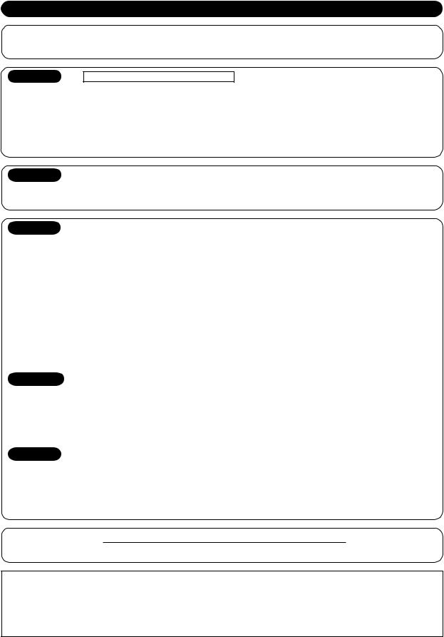
INSTALLATION DIAGRAM OF INDOOR AND OUTDOOR UNITS
(Attach
5 Filter
170 |
m |
|
m |
|
or |
|
m |
|
ore |
Air filter
to the fr ont p anel.)
6 Filter
3 Batteries
8 Pan head wood screw
2 Wireless remote control |
|
|
|
Remark : |
100 |
mm |
|
• Detail of accessory and installation |
|
||
|
|
||
parts can see in the accessory sheet. |
|
or |
more |
|
|
|
mmormore |
Hook |
|
|
65 |
|
|
|
1 Installation |
||
|
|
||
|
|
|
plate |
Hook |
|
170 |
mm |
|
|
||
|
|
|
|
|
|
|
or |
|
|
|
more |
Shield pipe
4 Remote control holder
Vinyl tape  Apply after carrying
out a drainage test.
mmormore |
more |
600 |
or |
mm |
|
|
100 |
|
Saddle |
|
|
|
Extension |
|
re |
|
drain hose |
|
o |
|
|
o |
m |
|
(Not available, |
r |
|
|
|
m |
|
|
provided by installer) |
m |
|
|
|
00 |
|
|
|
|
|
|
|
6 |
|
600 |
|
|
|
mm |
|
|
|
|
|
|
|
|
or |
|
|
|
more |
For the rear left and left piping
Wall
Insert the cushion between the indoor unit and wall, and tilt the indoor unit for better operation.
Do not allow the drain hose to get slack.
Cut the piping hole sloped slightly.
Make sure to run the drain hose sloped downward.
The auxiliary piping can be connected to the left, rear left, rear right, right, bottom right or bottom left.
Right |
|
|
|
Rear right |
|
Left |
|
Bottom |
Rear |
||
|
|||
right |
left |
Bottom left |
|
|
|
Insulate the refrigerant pipes separately with insulation, not together.
6 mm thick heat resisting polyethylene foam
ENGLISH
|
Optional Installation |
|
||
|
|
Parts |
|
|
|
|
|
|
|
Part |
|
Parts name |
Q’ty |
|
code |
|
|||
|
|
|
||
|
Refrigerant piping |
One |
||
A |
Liquid side |
: 6.35 mm |
||
each |
||||
|
Gas side |
: 12.70 mm |
||
|
|
|||
|
|
|
||
B |
Pipe insulating material |
1 |
||
(polyethylene foam, 6 mm thick) |
||||
|
|
|||
|
|
|
|
|
C |
Putty, PVC tapes |
One |
||
each |
||||
|
|
|
||
|
|
|
|
|
Fixing bolt arrangement of outdoor unit
•Secure the outdoor unit with fixing bolts and nuts if the
unit is likely to be exposed to |
|
|
|
|
|
|
108 mm |
|
|||
|
|
32.5 mm |
|
||||||||
a strong wind. |
|
|
|
||||||||
|
3 |
0 |
|||||||||
• Use 8 mm or 10 mm |
mm |
|
|
|
|
|
|
86 mm |
|
|
|
|
|
|
|
|
|
|
|
|
|||
anchor bolts and nuts. |
|
|
|
|
|
|
|
|
|
||
|
|
|
|
|
|
|
|
||||
• If it is necessary to drain the |
320 |
7 mm |
|
|
|
|
|
|
|
|
|
|
|
|
|
|
|
|
|
|
|||
defrost water, attach drain |
|
|
|
|
|
|
|||||
nipple 9 and cap water |
|
|
|
|
|
|
|
|
|
|
|
proof ! to the bottom plate |
|
|
|
|
|
|
Air outlet |
|
|||
of the outdoor unit before |
|
|
|
|
|
|
|
|
|
600 mm |
|
installing it. |
|
|
|
|
|
|
|
|
|
|
|
125 mm
Air inlet
 102 mm
90 mm
Drain outlet
2 |
EN |
INDOOR UNIT
Installation Place
•A place which provides the spaces around the indoor unit as shown in the diagram
•A place where there are no obstacles near the air inlet and outlet
•A place which allows easy installation of the piping to the outdoor unit
•A place which allows the front panel to be opened
CAUTION
•Direct sunlight to the indoor unit’s wireless receiver should be avoided.
•The microprocessor in the indoor unit should not be too close to RF noise sources.
(For details, see the owner’s manual.)
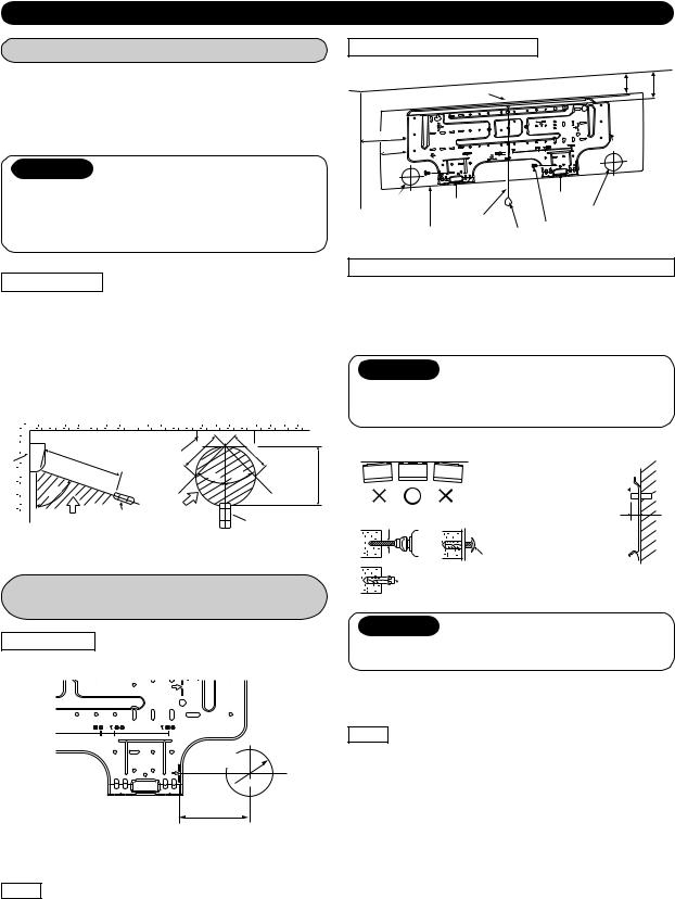
Mounting the installation plate
|
62 |
82.5 |
|
|
Hook |
|
|
170 |
|
|
|
85 |
|
|
|
|
Hook |
1 |
|
Hook |
Installation |
||
|
|||
Pipe hole |
plate |
||
Pipe hole |
|||
|
Thread |
|
|
Indoor unit |
Weight 7 Mounting screw |
|
When the installation plate is directly mounted on the wall
Remote control
•A place where there are no obstacles such as a curtain that may block the signal from the indoor unit
•Do not install the remote control in a place exposed to direct sunlight or close to a heating source such as a stove.
•Keep the remote control at least 1 m apart from the nearest TV set or stereo equipment. (This is necessary to prevent image disturbances or noise interference.)
•The location of the remote control should be determined as shown below.
1.Securely fit the installation plate onto the wall by screwing it in the upper and lower parts to hook up the indoor unit.
2.To mount the installation plate on a concrete wall with anchor bolts, use the anchor bolt holes as illustrated in the below figure.
3.Install the installation plate horizontally in the wall.
CAUTION
When installing the installation plate with a mounting screw, do not use the anchor bolt holes. Otherwise, the unit may fall down and result in personal injury and property damage.
Indoor unit
(Side view)
7 |
m |
° 75
Reception range
(Top view) |
|
|
Indoor unit |
5 |
m |
|
||
|
|
|
45° |
|
Remote |
Reception |
|
range |
||
control |
||
* : Axial distance |
||
|
|
5 |
|
|
m |
|
° |
m |
|
|
|
5 |
7 |
|
4 |
|
|
|
|
* |
Remote control
Cutting a Hole and Mounting
Installation Plate
Cutting a hole
When installing the refrigerant pipes from the rear
Pipe hole

 65 mm
65 mm
The center of the pipe hole
is above the arrow.
100 mm
Installation plate
(Keep horizontal direction.)
Anchor bolt 
Projection
15 mm or less
5 mm dia. hole
7 Mounting screw4 x 25 s
 Clip anchor (local parts)
CAUTION
Failure to firmly install the unit may result in personal injury and property damage if the unit falls.
•In case of block, brick, concrete or similar type walls, make 5 mm dia. holes in the wall.
•Insert clip anchors for appropriate mounting screws 7.
NOTE
•Secure four corners and lower parts of the installation plate with 4 to 6 mounting screws to install it.
1.After determining the pipe hole position on the mounting plate (A), drill the pipe hole ( 65 mm) at a slight downward slant to the outdoor side.
NOTE
•When drilling a wall that contains a metal lath, wire lath or metal plate, be sure to use a pipe hole brim ring sold separately.
EN |
3 |
Electrical Work
1.The supply voltage must be the same as the rated voltage of the air conditioner.
2.Prepare the power source for exclusive use with the air conditioner.
CAUTION
•This appliance can be connected to the mains in either of the following two ways.
(1)Connection to fixed wiring:
A switch or circuit breaker which disconnects all poles and has a contact separation of at least 3 mm must be incorporated in the fixed wiring. An approved circuit breaker or switches must be used.
(2)Connection with power supply plug:
Attach power supply plug with power cord and plug it into wall outlet. An approved power supply cord and plug must be used.
NOTE
• Ensure all wiring is used within its electrical rating.
Power source |
50Hz, 220 – 240 V Single phase |
|
|
Maximum running current |
12A |
|
|
Plug socket & fuse rating |
16A |
|
|
Power cord |
1.3 mm2 or more |
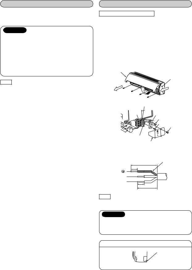
Wiring Connection
How to connect the power cord
For the air conditioner that does not have power cord, connect a power cord to it as mentioned below.
(1)Open the air inlet grille upward.
(2)Remove the four screws securing the front panel.
(3)Slightly open the lower part of the front panel, then pull the upper part of the front panel toward you to remove it from the rear plate.
(4)After removing the front panel, remove the power cord connect cover and the cord clamp.
(5)Connect and secure the power supply cord and secure the cord clamp and the power cord connect cover.
(6)Put the power supply cord through the notch.
(7)Be sure to smooth the notch with a file, etc.
Air inlet grille
Front panel
2 |
1 |
|
3 |
|
Earth line |
Terminal |
|
block |
Cord clamp |
|
Screw |
|
Screw |
Screw
Power supply cord
Power cord connect cover
Stripping length of the power supply cord
Earth line
40 mm
10 mm
N
L
10 mm
30 mm
NOTE
•Use stranded wire only.
•Wire type : H07RN-F or more
CAUTION
For the air conditioner with the power supply cord
•If the power supply cord is damaged, it must be replaced by the manufacturer, the service agency, or another similarly qualified person in order to avoid hazard.
Taking out the power cord
Notch
• Put the power supply cord through the notch.
4 |
EN |

How to connect the connecting cable
Wiring of the connecting cable can be carried out without removing the front panel.
1.Remove the air inlet grille.
Open the air inlet grille upward and pull it toward you.
2.Remove the terminal cover and cord clamp.
3.Insert the connecting cable (according to the local cords) into the pipe hole on the wall.
4.Take out the connecting cable through the cable slot on the rear panel so that it protrudes about 15 cm from the front.
5.Insert the connecting cable fully into the terminal block and secure it tightly with screws.
6.Tightening torque : 1.2 N·m (0.12 kgf·m)
7.Secure the connecting cable with the cord clamp.
8.Fix the terminal cover, rear plate bushing and air inlet grille on the indoor unit.
CAUTION
•Be sure to refer to the wiring system diagram labeled inside the front panel.
•Check local electrical cords and also any specific wiring instructions or limitations.
For Heatpump model
Cord clamp
Terminal cover |
Terminal block |
Earth line |
|
Screw |
|
|
|
|
|
|
|
80 mm |
|
|
|
|
|
|
4 |
10 mm |
70 mm |
|
Connecting cable |
|
|
|
|
|
|
|
||
1 |
2 |
3 |
4 |
1 |
2 |
|
|
||
3 |
|
|
|||||||
|
|
|
|
|
|
|
|
10 mm |
|
about |
15 |
cm |
Earth line |
10 mm |
|
|
|||
|
|
|
50 mm |
|
|
|
|
|
|
|
|
Screw |
|
Stripping length of |
|
|
Connecting |
the connecting cable |
|
|
|
Screw |
|
cable
For Cooling model
|
Cord clamp |
Terminal block |
Earth line |
||
|
|
|
|||
Terminal cover |
|
|
|||
|
|
|
60 mm |
||
|
|
|
|
|
|
|
Screw |
|
|
|
10 mm |
Connecting cable |
|
|
|
|
|
1 |
2 |
1 |
2 |
|
|
about |
|
15 |
cm |
|
Screw
Screw
NOTE
•Use stranded wire only.
•Wire type : H07RN-F or more
Earth line
10 mm
50 mm
Stripping length of Connecting the connecting cable cable
How to install the air inlet grille on the indoor unit
•When attaching the air inlet grille, the contrary of the removed operation is performed.
Piping and Drain Hose Installation
Piping and drain hose forming
*Since dewing results in a machine trouble, make sure to insulate both connecting pipes. (Use polyethylene foam as insulating material.)
Rear right
Rear left |
|
|
|
|
Changing drainhose |
preparationPiping |
|
|
|
|
|
||
|
|
|
|
|||
Bottom left |
|
cutting-Die |
slitpanelfront |
|||
|
|
|
|
|
|
|
|
|
|
|
|
|
|
|
|
|
|
|
|
|
Left |
|
|
|
|
|
|
|
|
|
|
|
|
|
|
|
|
|
|
|
|
Bottom right |
|
|
|
|
|
|
|
|
|
|
|
|
|
|
|
|
|
|
|
|
Right |
|
|
|
|
|
|
|
|
|
|
|
|
|
1. Die-cutting front panel slit
For leftward connection, cut out slit on the left side of the front panel. (A knife will produce splinters, so use nippers.)
2. Changing drain hose
For leftward connection, bottom-leftward connection and rearleftward connection’s piping, it is necessary to change the drain hose and drain cap.
How to remove the drain cap
Clip the drain cap by needle-nose pliers and pull out.
How to install the drain hose
Firmly insert drain hose connecting part until hitting on a heat insulator.
Heat insulator
Drain hose
How to fix the drain cap
1) Insert hexagon wrench (4 mm) in a center head.
4 mm
2) Firmly insert the drain cap.
No gap
Do not apply lubricating oil (refrigerant machine oil) when
 inserting the drain cap. Application causes deterioration and drain
 leakage of the plug. Insert a hexagon
wrench (4 mm).
CAUTION
Firmly insert the drain hose and drain cap; otherwise, water may leak.
EN |
5 |
In case of right or left piping
•After scribing slits of the front panel with a knife or a making-off pin, cut them with a pair of nippers or
an equivalent tool.
Slit
In case of bottom right or bottom left piping
•After scribing slits of the front panel with a knife or a making-off pin, cut them
with a pair of nippers or |
Slit |
an equivalent tool. |
|
Left-hand connection with piping
Bend the connecting pipe so that it is laid within 43 mm above the wall surface. If the connecting pipe is laid exceeding 43 mm above the wall surface, the indoor unit may unstably be set on the wall.
When bending the connecting pipe, make sure to use a spring bender so as not to crush the pipe.
Bend the connecting pipe within a radius of 30 mm.
To connect the pipe after installation of the unit (figure)
(To the forefront of flare)
|
270 mm |
Liquid side |
|
|
|
|
170 mm |
Gas side |
|
|
|
|
|
Outward form of indoor unit |
mm |
R 30 mm (Use polisin (polyethylene) |
|
43 |
core or the like for bending pipe.) |
|
|
||
|
8 |
Use the handle of screwdriver, etc. |
|
0 |
|
NOTE
If the pipe is bent incorrectly, the indoor unit may unstably be set on the wall.
After passing the connecting pipe through the pipe hole, connect the connecting pipes to the auxiliary pipes and wrap the facing tape around them.
CAUTION
•Bind the auxiliary pipes (two) and connecting cable with facing tape tightly. In case of leftward piping and rear-leftward piping, bind the auxiliary pipes (two) only with facing tape.
 Indoor unit
Auxiliary pipes 

 Connecting cable
Installation plate 
•Carefully arrange pipes so that any pipe does not stick out of the rear plate of the indoor unit.
•Carefully connect the auxiliary pipes and connecting pipes to one another and cut off the insulating tape wound on the connecting pipe to avoid double-taping at the joint; moreover, seal the joint with the vinyl tape, etc.
•Since dewing results in a machine trouble, make sure to insulate both connecting pipes. (Use polyethylene foam as insulating material.)
•When bending a pipe, carefully do it, not to crush it.
Indoor Unit Fixing
1.Pass the pipe through the hole in the wall and hook the indoor unit on the installation plate at the upper hook.
2.Swing the indoor unit to right and left to confirm that it is firmly hooked up on the installation plate.
3.While pressing the indoor unit onto the wall, hook it at the lower part on the installation plate. Pull the indoor unit toward you to confirm that it is firmly hooked up on the installation plate.
Hook here.
1
 1 Installation plate
2
Hook
Press (unhook)
•For detaching the indoor unit from the installation plate, pull the indoor unit toward you while pushing its bottom up at the specified parts.
Push Push
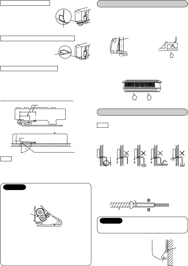
Drainage
1. Run the drain hose sloped downwards.
NOTE
•The hole should be made at a slight downward slant on the outdoor side.
|
Do not form the |
Do not rise the |
drain hose into |
drain hose. |
a wavy shape. |
50 mm or more
Do not put the |
Do not put the |
drain hose end |
drain hose end |
into water. |
in the drainage |
|
ditch. |
2.Put water in the drain pan and make sure that the water is drained out of doors.
3.When connecting extension drain hose, insulate the connecting part of extension drain hose with shield pipe.
Shield pipe
Extension drain hose
Drain hose |
Inside the room |
CAUTION
Arrange the drain pipe for proper drainage from the unit. Improper drainage can result in dew-dropping.
This air conditioner has the |
Wall |
|
structure designed to drain |
Drain |
|
water collected from dew, which |
||
forms on the back of the indoor |
guide |
|
|
||
unit, to the drain pan. Therefore, |
|
|
do not store the power cord and |
|
|
other parts at a height above |
Space for pipes |
|
the drain guide. |
||
|
6 |
EN |
OUTDOOR UNIT
Installation Place
•A place which provides the spaces around the outdoor unit as shown in the diagram
•A place which can bear the weight of the outdoor unit and does not allow an increase in noise level and vibration
•A place where the operation noise and discharged air do not disturb your neighbors
•A place which is not exposed to a strong wind
•A place free of a leakage of combustible gases
•A place which does not block a passage
•When the outdoor unit is to be installed in an elevated position, be sure to secure its feet.
•An allowable length of the connecting pipe is up to 15 m.
•An allowable height level is up to 6 m.
•A place where the drain water does not raise any problems
CAUTION
1.Install the outdoor unit without anything blocking the air discharging.
2.When the outdoor unit is installed in a place always exposed to strong wind like a coast or on a high storey of a building, secure the normal fan operation using a duct or a windshield.
3.In particularly windy areas, install the unit such as to avoid admission of wind.
4.Installation in the following places may result in trouble. Do not install the unit in such places.
•A place full of machine oil
•A saline-place such as the coast
•A place full of sulfide gas
• A place where highfrequency waves are likely to be generated as from audio equipment, welders, and medical equipment
|
(Unit : N·m) |
Outer dia. of copper pipe |
Tightening torque |
|
|
6.35 mm |
16 to 18 (1.6 to 1.8 kgf·m) |
|
|
12.70 mm |
50 to 62 (5.0 to 6.2 kgf·m) |
|
|
• Tightening torque of flare pipe connections
The operating pressure of R410A is higher than that of R22 (approx. 1.6 times). It is therefore necessary to firmly tighten the flare pipe connecting sections (which connect the indoor and outdoor units) up to the specified tightening torque. Incorrect connections may cause not only a gas leakage, but also damage to the refrigeration cycle.
Flare at
indoor unit side
|
Mark line |
Flare at |
|
outdoor unit side |
|
Half union |
Flare nut |
Externally |
Internally |
threaded side |
threaded side |
Use a wrench to secure. |
Use a torque wrench to tighten. |
Refrigerant Piping Connection
1. Cut the pipe with a pipe cutter.
90 |
Obliquity |
Roughness |
Warp |
|
|
|
2.Insert a flare nut into the pipe and flare the pipe.
• Projection margin in flaring : A (Unit : mm)
Rigid (clutch type)
Outer dia. |
R410A tool used |
Conventional tool used |
|
of copper pipe |
|||
|
|
||
|
|
|
|
6.35 |
0 to 0.5 |
1.0 to 1.5 |
|
|
|
|
|
12.70 |
0 to 0.5 |
1.0 to 1.5 |
Imperial (wing nut type, conventional tool)
|
A |
Outer dia. of copper pipe |
R410A |
|
|
6.35 |
1.5 to 2.0 |
Die |
Pipe |
12.70 |
2.0 to 2.5 |
|
|
||
|
|
|
Tightening connection
Align the centers of the connecting pipes and tighten the flare nut as far as possible with your fingers. Then tighten the nut with a spanner and torque wrench as shown in the figure.
CAUTION
Do not apply excess torque. Otherwise, the nut may crack depending on the conditions.
EN |
7 |
 Loading...