


 Loading...
TEC Electronic Computing Scale
SL-9000/9000N-FFB SERIES
Owner’s Manual
Table of Contents

Safety Summary
Safety Summary
Personal safety in handling or maintaining the equipment is extremely important. Warnings and Cautions necessary for safe handling are included in this manual. All warnings and cautions contained in this manual should be read and understood before handling or maintaining the equipment.
Do not attempt to effect repairs or modifications to this equipment. If a fault occurs that cannot be rectified using the procedures described in this manual, turn off the power, unplug the machine, then contact your authorized TOSHIBA TEC representative for assistance.
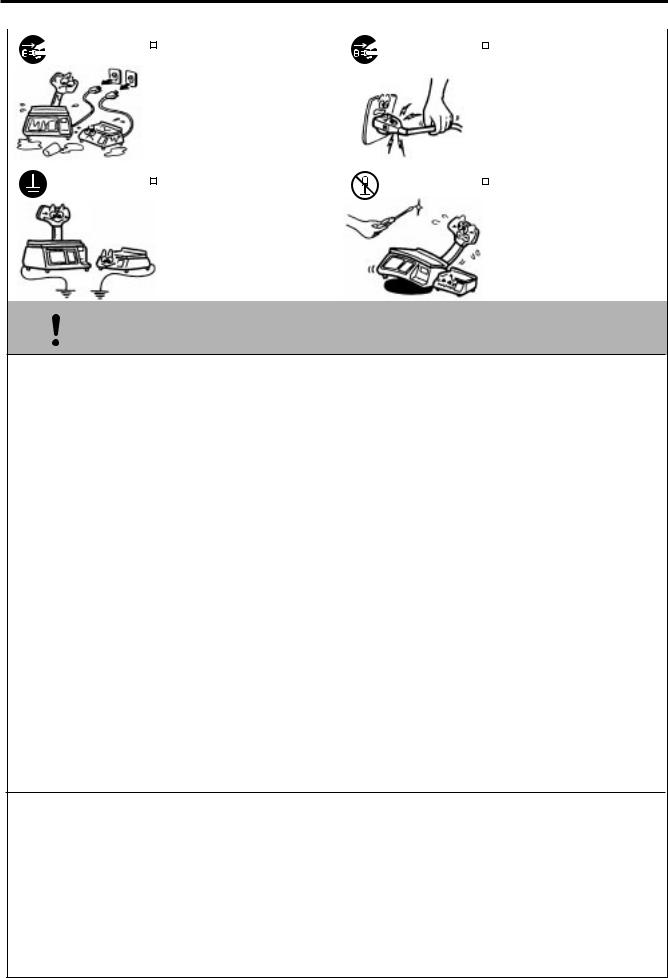
Meanings of Each Symbol
This symbol indicates warning items (including cautions). Specific warning contents are drawn inside the  symbol. (The symbol on the left indicates a general caution.)
This symbol indicates prohibited actions (prohibited items). Specific prohibited contents are drawn inside or near the symbol. (The symbol on the left indicates “no disassembling”.)
This symbol indicates actions which must be performed. Specific instructions are drawn inside or near the symbol.
(The symbol on the left indicates “disconnect the power cord plug from the outlet”.)
|
|
This indicates that there is the risk of death or serious injury if the |
||||
WARNING machines are improperly handled contrary to this indication. |
||||||
Any other than the |
|
Do not use voltages other than the |
Prohibited |
|
Do not plug in or unplug the power |
|
specified AC voltage |
|
|
||||
voltage (AC) specified on the rating |
cord plug with wet hands as this may |
|||||
is prohibited. |
|
|||||
|
plate, as this may cause fire or |
|
cause electric shock. |
|||
|
electric shock. |
|
|
|
||
Prohibited |
|
If the machines share the same |
Prohibited |
|
|
Do not place metal objects or |
|
|
|
||||||
|
|
||||||
outlet with any other electrical |
water-filled containers such as flower |
||||||
|
|
||||||
|
appliances which consume large |
|
vases, flower pots or mugs, etc. on |
||||
|
amounts of power, the voltage will |
|
top of the machines. If metal objects |
||||
|
fluctuate widely each time these |
|
or spilled liquid enter the machines, |
||||
|
appliances operate. Be sure to |
|
this may cause fire or electric |
||||
|
provide an exclusive outlet for the |
|
shock. |
||||
|
machine as this may cause the |
|
|
|
|
||
|
machines to malfunction. |
|
|
|
|
||
|
|
|
|
|
|
|
|
Prohibited |
|
Do not insert or drop metal, |
Prohibited |
|
|
Do not scratch, damage or modify |
|
|
|
|
|||||
|
|
|
|||||
flammable or other foreign objects into |
the power cords. Also, do not place |
||||||
|
|
||||||
|
the machines through the ventilation |
|
heavy objects on, pull on, or exces- |
||||
|
slits, as this may cause fire or electric |
|
sively bend the cords, as this may |
||||
|
shock. |
|
cause fire or electrical shock. |
||||
Disconnect |
|
If the machines are dropped or their |
Disconnect |
|
Continued use of the machines in an |
|
|
||||
the plug. |
cabinets damaged, first turn off the |
the plug. |
abnormal condition such as when the |
||
|
power switches and disconnect the |
|
machines are producing smoke or |
||
|
power cord plugs from the outlet, and |
|
strange smells may cause fire or elec- |
||
|
then contact your authorized |
|
tric shock. In these cases, immedi- |
||
|
TOSHIBA TEC representative for |
|
ately turn off the power switches and |
||
|
assistance. Continued use of the |
|
disconnect the power cord plugs from |
||
|
|
the outlet. Then, contact your author- |
|||
|
machine in that condition may cause |
|
|||
|
|
ized TOSHIBA TEC representative for |
|||
|
fire or electric shock. |
|
|||
|
|
assistance. |
|||
|
|
|
|
||
(i)
Safety Summary
|
|
Disconnect |
|
If foreign objects (metal fragments, |
Disconnect |
|
|
When unplugging the power cords, |
|
|
|
|
|
||||
|
|
|
|
|
||||
|
|
the plug. |
water, liquids) enter the machines, |
the plug. |
be sure to hold and pull on the plug |
|||
|
|
|
first turn off the power switches and |
|
portion. Pulling on the cord portion |
|||
|
|
|
disconnect the power cord plugs from |
|
may cut or expose the internal wires |
|||
|
|
|
the outlet, and then contact your |
|
and cause fire or electric shock. |
|||
|
|
|
authorized TOSHIBA TEC repre- |
|
|
|
|
|
|
|
|
sentative for assistance. Continued |
|
|
|
|
|
|
|
|
use of the machine in that condition |
|
|
|
|
|
|
|
|
may cause fire or electric shock. |
|
|
|
|
|
|
|
|
|
|
|
|
|
|
|
|
Connect a |
|
Ensure that the equipment is |
No disassem- |
|
|
Do not remove covers, repair or |
|
|
grounding |
|
|
|
|||
|
|
properly grounded. Extension cables |
bling. |
modify the machine by yourself. You |
||||
|
|
wire. |
||||||
|
|
|||||||
|
|
should also be grounded. Fire or |
|
may be injured by high voltage, very |
||||
|
|
|
|
|||||
|
|
|
|
hot parts or sharp edges inside the |
||||
|
|
|
electric shock could occur on |
|
||||
|
|
|
|
machine. |
||||
|
|
|
improperly grounded equipment. |
|
||||
|
|
|
|
|
|
|
||
|
|
|
|
|
|
|
|
|
 CAUTIONThis indicates that there is the risk of personal Injury or damage to objects if the machines are improperly handled contrary to this indication.
Precautions
The following precautions will help to ensure that this machine will continue to function correctly.
•Try to avoid locations that have the following adverse conditions:
* |
Temperatures out of the specification |
* |
Direct sunlight |
* |
High humidity |
* |
Shared power source |
* |
Excessive vibration |
* |
Dust/Gas |
•Do not subject the machine to sudden shocks.
•Do not press the keys too hard. Keys will operate correctly if they are touched lightly.
•Clean the cover and keyboard, etc. by wiping with a dry cloth or a cloth soaked with detergent and wrung out thoroughly. Never use thinner or other volatile solvent for cleaning.
•To ensure that the scale is operating correctly, place a known weight on the platter and check it for correct weight measurement. This should be done every morning before starting normal operations.
•When moving the machine, take hold of the case and lift the machine. Never hold the remote unit.
•Do not place the machines on unstable or slanted surfaces, as they may drop or fall and cause injury.
•USE ONLY TOSHIBA TEC SPECIFIED paper.
•DO NOT STORE the paper or ribbons where they might be exposed to direct sunlight, high temperatures, high humidity, dust, or gas.
•Ensure the machine is operated on a level surface.
•Any data stored in the memory of the machine could be lost during a machine fault.
•Try to avoid using this equipment on the same power supply as high voltage equipment or equipment likely to cause mains interference.
•Unplug the machine whenever you are working inside it or cleaning it.
•Keep your work environment static free.
•Do not place heavy objects on top of the machines, as these items may become unbalanced and fall causing injury.
•Do not block the ventilation slits of the machines, as this will cause heat to build up inside the machines and may cause fire.
•Do not lean against the machine. It may fall on you and could cause injury.
•Care must be taken not to injure yourself with the printer paper cutter.
•Unplug the machine when it is not used for a long period of time.
Request Regarding Maintenance
•Utilize our maintenance services.
After purchasing the machine, contact your authorized TOSHIBA TEC representative for assistance once a year to have the inside of the machine cleaned. Otherwise, dust will build up inside the machines and may cause a fire or a malfunction. Cleaning is particularly effective before humid rainy seasons.
•Our preventive maintenance service performs the periodic checks and other work required to maintain the quality and performance of the machines, preventing accidents beforehand.
For details, please consult your authorized TOSHIBA TEC representative for assistance.
•Using insecticides and other chemicals
Do not expose the machines to insecticides or other volatile solvents. This will cause the cabinet or other parts to deteriorate or cause the paint to peel.
(ii)

TABLE OF CONTENTS
|
|
Page |
1.INTRODUCTION ............................................................................................. |
1-1 |
|
1.1 |
APPLICABLE MODEL ........................................................................... |
1-2 |
1.2 |
ACCESSORIES .................................................................................... |
1-2 |
2.SPECIFICATIONS ........................................................................................... |
2-1 |
|
2.1 |
SCALE ................................................................................................... |
2-1 |
2.2 |
OPTION ................................................................................................. |
2-2 |
3.APPEARANCE ................................................................................................ |
3-1 |
|
4.DISPLAY .......................................................................................................... |
4-1 |
|
4.1 |
US TYPE ............................................................................................... |
4-1 |
4.2 |
CA/QR TYPE ......................................................................................... |
4-1 |
5.KEY LAYOUT .................................................................................................. |
5-1 |
|
5.1 |
PROGRAMMING KEYBOARD ............................................................. |
5-1 |
5.2 |
OPERATION KEYBOARD AND SPEED KEYBOARD.......................... |
5-3 |
5.3 |
SELF SERVICE KEYBOARD ................................................................ |
5-5 |
6.PROCEDURE BEFORE OPERATION ............................................................ |
6-1 |
|
7.INSTALLATION PROCEDURE ....................................................................... |
7-1 |
|
8.LEVEL ADJUSTMENT .................................................................................... |
8-1 |
|
9. REMOVAL AND REPLACEMENT OF MEDIA ................................................ |
9-1 |
|
10. OUTLINE OF OPERATION ............................................................................. |
10-1 |
|
11. PROGRAMMING PROCEDURES .................................................................. |
11-1 |
|
11.1 |
UNIT PRICE CHANGE .......................................................................... |
11-4 |
11.2 |
PLU DATA SETTING ............................................................................ |
11-5 |
11.3 |
INGREDIENT MESSAGE ..................................................................... |
11-7 |
11.4 |
NUTRITION FACTS .............................................................................. |
11-8 |
11.5 |
PLU VERIFYING LABEL ....................................................................... |
11-12 |
11.6 |
ADDRESS AND COMMERCIAL MESSAGE SETTING ........................ |
11-13 |
11.7 |
COMBINATION MESSAGE .................................................................. |
11-14 |
11.8 |
SPECIAL INFORMATION ..................................................................... |
11-16 |
11.9 |
GRADE LINE ......................................................................................... |
11-16 |
11.10 |
SPEED KEY SETTING ......................................................................... |
11-17 |
11.11 |
PRINT FORMAT.................................................................................... |
11-18 |
11.12 |
DATE/TIME SETTING ........................................................................... |
11-20 |
11.13 |
CMT/PL-3 .............................................................................................. |
11-20 |
11.14 |
IN-LINE/LOCAL ..................................................................................... |
11-23 |
11.15 |
LON SYSTEM ....................................................................................... |
11-24 |
11.16 |
BAR CODE FORMAT ........................................................................... |
11-26 |
11.17 |
TITLES .................................................................................................. |
11-28 |
11.18 |
TRANSFERRING LOGO DATA ............................................................ |
11-29 |
11.19 |
IDIOM SETTING.................................................................................... |
11-31 |
11.20 |
VENDOR SETTING .............................................................................. |
11-31 |
11.21 |
FREE FORMAT SETTING .................................................................... |
11-32 |

|
|
Page |
12.PROGRAMMED DATA VERIFICATION REPORTS ....................................... |
12-1 |
|
13.PASSWORD SECURITY ................................................................................. |
13-1 |
|
13.1 |
SETTING PASSWORD AND PROTECT MENU................................... |
13-1 |
13.2 |
CALLING MENU BY ENTERING PASSWORD .................................... |
13-3 |
14.OPERATING PROCEDURES ......................................................................... |
14-1 |
|
14.1 |
WEIGHING OPERATION ...................................................................... |
14-2 |
14.2 |
FIX PRICE OPERATION (FOR US TYPE ONLY)................................. |
14-3 |
14.3 |
BY COUNT OPERATION ...................................................................... |
14-4 |
14.4 |
PRINT COUNT OPERATION ................................................................ |
14-6 |
14.5 |
ISSUING LABELS WITH NET WEIGHT STATEMENT |
|
|
(FOR US TYPE ONLY) ......................................................................... |
14-9 |
14.6 |
TARE/SAVE FUNCTION PROCEDURES ............................................ |
14-11 |
14.7 |
CALLING AND PRINTING GRADE LINE ............................................. |
14-12 |
14.8 |
CALLING AND PRINTING LOGOS ...................................................... |
14-13 |
14.9 |
SELECTING PRINT ITEM ..................................................................... |
14-14 |
14.10 |
DATE CHANGE .................................................................................... |
14-15 |
14.11 |
BATCH PRINT MODE (with 30 Items Run Assignment) ....................... |
14-16 |
14.12 |
VISUAL COMMODITY LIBRARY .......................................................... |
14-19 |
14.13 |
FLOATING VENDOR ............................................................................ |
14-20 |
15.TOTAL OPERATION ....................................................................................... |
15-1 |
|
15.1 |
HOURLY TOTAL REPORT ................................................................... |
15-2 |
15.2 |
GRAND TOTAL REPORT ..................................................................... |
15-2 |
15.3 |
PLU TOTAL REPORT ........................................................................... |
15-2 |
15.4 |
VENDOR TOTAL REPORT................................................................... |
15-3 |
16.ERROR MESSAGE TABLE ............................................................................. |
16-1 |
|
17.CLEANING THE PRINT HEAD ....................................................................... |
17-1 |
|
18.TROUBLESHOOTING ..................................................................................... |
18-1 |
|
CAUTION:
1.This manual may not be copied in whole or in part without prior written permission of TOSHIBA TEC.
2.The contents of this manual may be changed without notification.
3.Please refer to your local Authorized Service representative with regard to any queries you may have in this manual.
Copyright © 2000
by TOSHIBA TEC CORPORATION All Rights Reserved
570 Ohito, Ohito-cho, Tagata-gun, Shizuoka-ken, JAPAN

1. INTRODUCTION
EM1-31064
1. INTRODUCTION
1. INTRODUCTION
Thank you for purchasing the TEC SL-9000 Series electronic computing scale. As you will discover, the TEC SL-9000 series has many features and functions designed for user friendliness as well as complete customer satisfaction.
The 256 x 64 dot fluorescent display provides customers with ample information, the 140 speed keys realize a higher degree of operability, and the 3 inch/sec. print speed ensures fast and clear printing. Password security prevents unauthorized access to the PROG., M.DOWN, REWRAP, REPORT and RESET mode. The latest high speed in-line system, Local Operation Network (LON), allows easy system configuration and greater throughput.
Various options, including a TMCC interface, RS-232C interface, etc., are selectable in accordance with your needs.
We believe that your needs will now be fully satisfied, and you will have total reliability in price calculations. Should you have any questions concerning the scale, please refer to this manual. Be sure to keep this manual for future reference.
This equipment has been tested and found to comply with the limits for a Class A digital device, pursuant to Part 15 of the FCC Rules. These limits are designed to provide reasonable protection against harmful interference when the equipment is operated in a commercial environment. This equipment generates, uses, and can radiate radio frequency energy and, if not installed and used in accordance with the instruction manual, may cause harmful interference to radio communications. Operations of this equipment in a residential area is likely to cause harmful interference in which case the user will be required to correct the interference at his own expense. (for USA only)
Changes or modifications not expressly approved by manufacturer for compliance could void the user’s authority to operate the equipment.
“This Class A digital apparatus meets all requirements of the Canadian Interference-Causing Equipment Regulations.”
“Cet appareil numéique de la classe A respecte toutes les exigences du Rèlement sur le matériel brouilleur du Canada.”
(for CANADA only)
Some procedures described in this manual may be illegal in various state jurisdictions. When there are optional settings to enable various functions or to disable functions. Please ensure that the optional settings for scale operation meet the local requirements of weights and measures. If you are uncertain of specific items, contact the state or county office of weights and measures for clarification.
1-1
1. INTRODUCTION |
EM1-31064 |
1.1 APPLICABLE MODEL
1.1 APPLICABLE MODEL
∙ |
SL-9000-15M-FFB-CA |
∙ |
SL-9000-30M-N-FFB-US |
∙ |
SL-9000-15M-FFB-QR |
∙ |
SL-9000-15M-N-FFB-CA |
|
|
∙ |
SL-9000-15M-N-FFB-QR |
The description of the model number is as follows.
S L - 9 0 0 0 - 3 0 M - N - F F B - U S
Max. Capacity
30M: 30 lbs (decimal pound/multi-interval)
15M: 15 Kg (multi-interval)
 Destination Code
ex.) US, CA, QR etc.
Keyboard Type
B: Built-in keyboard
Display Type
FF:Fluorescent full dot display
N:LAN (option) is available.
Blank: LAN (option) is not available.
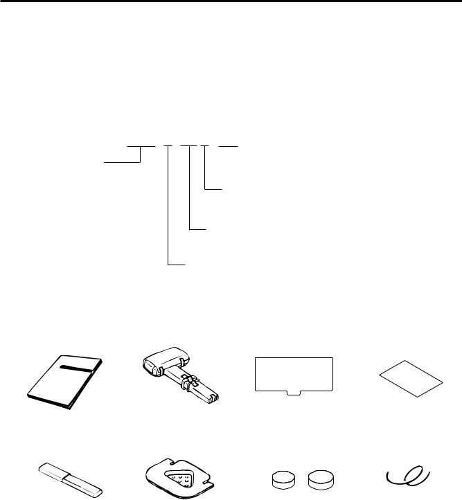
1.2 ACCESSORIES
Owner's Manual |
Remote Display |
Speed Key Sheet |
Quality Control Report |
(EM1-31064) |
|
|
(US type only) |
Print Head Cleaner |
Remote Blind Plate |
Sealing Lead |
Stranded Wire |
|||
(24089500013) |
|
|
|
|
|
|
|
|
|
|
|
|
|
|
|
|
|
|
|
|
NOTE: Check that there are no missing or incorrect parts in the accessories.
1-2

2. SPECIFICATION
EM1-31064
2.1 SCALE
2. SPECIFICATION
2.1 SCALE
Item |
US |
CA |
QR |
|
|
|
|
Maximum Capacity |
30 lb |
15 Kg (30 lb) |
|
Minimum Scale Division |
0.005 lb (0~15 lb) |
0.002 Kg (0 ~ 6 Kg) |
|
|
|
0.005 Kg (6 ~ 15 Kg) |
|
|
0.01 lb (15~30 lb) |
0.005 lb (0 ~ 15 lb) |
|
|
|
0.01 lb (15 ~ 30 lb) |
|
Maximum Tare |
2.000 lb |
1.000 Kg (2.205 lb) |
|
Display Range |
0 ~ 30.05 lb |
0 ~ 15.025 Kg (0 ~ 30.05 lb) |
|
|
|
|
|
Unit Price Presettable |
$0.01 ~ 99.99 |
$0.01 ~ 99.99 |
0 ~ 99999 |
Minimum Price Display |
$0.01 |
$0.01 |
1 |
|
|
|
|
Power Requirement |
AC 120 V ± 10%, 60 Hz (US/CA type) |
|
|
|
AC 220 V ± 10%, 50/60 Hz (QR type) |
|
|
Power Consumption |
US/CA: 66 W, 1.1 A (Standby: 26 W, 0.39 A) |
|
|
|
QR: 70 W, 0.66 A (Standby: 32 W, 0.26 A) |
|
|
Temperature Limits |
32°F ~ 104°F (0°C ~ 40°C) |
|
|
Relative Humidity |
35% ~ 85% (No condensation) |
|
|
Message Display |
256 x 64 dots Fluorescent display |
|
|
Weight |
5 digits (US/CA type), 5 digits (QR type) |
|
|
Unit Price |
4 digits (US/CA type), 5 digits (QR type) |
|
|
Total Price |
5 digits (US/CA type), 6 digits (QR type) |
|
|
Remote Display Mode |
Dual sides |
|
|
Capacity of PLU Memory |
560 PLUs (Standard), 240 PLUs when LOGO is available. |
||
(SL-9000) |
3120 PLUs max. (Option) |
|
|
Capacity of PLU Memory |
3600 PLUs max. (Standard) |
|
|
(SL-9000N) |
|
|
|
Print Head |
Thermal Print Head (2 inch wide) |
|
|
Media Issue Method |
On-demand/Batch |
|
|
Dot Density |
193 dots/inch (7.6 dots/mm) |
|
|
Print Speed |
3 inch/sec. (76.2 mm/sec.) |
|
|
Available Media Width |
1.89 inch (48 mm), 2.24 inch (57 mm) |
|
|
Recommended Media |
|
|
|
Thermal Label |
VHTS, VLTB (OSP)/Outer diameter: Ø93 mm (Max.) |
||
Variable Length Label |
VHTS, VLTB (OSP)/Outer diameter: Ø90 mm (Max.) |
||
Thermal Receipt |
120 FC (RICOH)/Outer diameter: Ø81 mm (Max.) |
|
|
Interface |
CMT/PL-3 interface (Program Loader) |
|
|
|
LON interface (RS-485) |
|
|
|
PC-AT KEY interface (Option) |
|
|
|
TMCC interface (Option) |
|
|
|
Drawer interface (Exact interface) |
|
|
|
LAN interface (10 Base T, SL-9000N Option) |
|
|
Dimensions (approx.) |
17.2 inch (width)x16.8 inch (depth) x 18.7 inch (height) |
||
|
436 mm (width)x426 mm (depth) x 474 mm (height) |
||
Weight |
33 lb (15 Kg) |
|
|
|
|
|
|
2-1
2. SPECIFICATION
EM1-31064
2.2 OPTION
2.2 OPTION
Option Name |
Model No. |
|
|
Description |
|
Source |
|||
or Part No. |
|
|
|
||||||
|
|
|
|
|
|
|
|
||
|
LON Connector |
Part No. |
A modular connector used to connect scales |
See |
|||||
|
TM8P-88P |
EAJ-0028001 |
to each other in a LON configuration. |
Note 2 |
|||||
|
|
|
|
|
|||||
|
LON Terminal |
Part No. |
A modular resistor attached to the scales |
See |
|||||
|
Resistor 285D-8P |
EAJ-0029001 |
connected |
at |
both |
ends of |
the LON |
Note 2 |
|
LON |
|
|
configuration. |
|
|
|
|||
|
|
|
|
|
|
||||
|
|
|
|
|
|||||
|
LON Cable |
Part No. |
An 8-pin telephone cable used with the LON |
|
|||||
|
S-STLAN-2P |
10319100003 |
connectors attached to both ends of the |
See |
|||||
|
(200 m/roll) |
|
cable. This cable connects scales to each |
Note 2 |
|||||
|
|
|
other in a LON configuration. |
|
|
||||
|
|
|
|
|
|||||
|
External Connector |
OP-9000-IOEC-B |
A junction box to which the TMCC kit is |
See |
|||||
|
Box |
|
attached. |
It is |
also |
used with |
the RS-232 |
||
|
|
|
CL/CS kit. |
|
|
|
|
Note 1 |
|
|
|
|
|
|
|
|
|
||
|
|
|
|
|
|||||
|
I/O PC Board |
OP-9000-IOB |
An I/O board equipped with the TMCC |
|
|||||
TMCC |
|
|
interface and PC-AT keyboard interface ports. |
See |
|||||
|
|
It is used to construct a TMCC system and |
Note 1 |
||||||
|
|
|
|||||||
|
|
|
program PLU data, etc. |
|
|
||||
|
TMCC Cable Kit |
OP-9000-IOCN- |
A cable kit for the TMCC interface |
See |
|||||
|
|
|
|
|
|
||||
|
|
TMCC |
|
|
|
|
|
Note 1 |
|
|
|
|
|
|
|||||
|
|
OP-9000- |
This board is used to expand the PLU |
|
|||||
MEMO PC Board |
PIGGYBACK |
memory to 4MB by installing the memory |
See |
||||||
(SL-9000 only) |
OP-9000- |
module. |
|
|
|
|
Note 1 |
||
|
|
PIGGYBACK-S/F |
|
|
|
|
|
|
|
|
|
|
|
|
|||||
|
|
OP-9000-RAM- |
DIP type PS-RAM to be installed on the |
|
|||||
|
|
512KB |
MEMO PC board (OP-9000-PIGGYBACK) for |
|
|||||
|
|
|
memory expansion. |
|
|
|
|||
|
|
|
When expanding the memory, install the two |
See |
|||||
Memory Module |
|
modules as one set. |
|
|
Note 1 |
||||
OP-9000-SRAM- |
DIP type S-RAM to be installed on the MEMO |
||||||||
|
|
and 3 |
|||||||
|
|
PC board |
(OP-9000-PIGGYBACK-S/F) for |
||||||
|
|
512KB |
|||||||
|
|
|
|||||||
|
|
memory expansion. |
|
|
|
||||
|
|
|
|
|
|
||||
|
|
|
When expanding the memory, install the two |
|
|||||
|
|
|
modules as one set. |
|
|
|
|||
|
|
|
|
|
|||||
Label Cassette |
OP-9000- |
It is covenient to change several kinds of |
See |
||||||
|
|
CASSETTE |
labels. |
|
|
|
|
Note 1 |
|
|
|
|
|
||||||
10 Base T (LAN) |
OP-9000N-LAN |
This board enables the SL-9000N to be used |
See |
||||||
Interface Board |
|
in a LAN network. |
|
|
Note 1 |
||||
(SL-9000N only) |
|
|
|
|
|
|
|
||
|
|
|
|
|
|
|
|
|
|
NOTES: 1. Contact TOSHIBA TEC H.Q. or your nearest TOSHIBA TEC representative.
2.Order from TOSHIBA TEC Parts Center or purchase locally.
3.When purchasing memory modules locally, select one having the following specifications.
■ Maker: HITACHI Pseudo Static RAM (OP-9000-RAM-512KB)
HITACHI Static RAM (OP-9000-SRAM-512KB)
■ Type: HM658512ALP-8V80ns, 600mil 32-pin Plastic DIP (DP-32) (OP-9000-
RAM-512KB)
HM628512ALP-770ns, 600mil 32-pin Plastic DIP (DP-32) (OP-9000-
SRAM-512KB)
4.The Memo PC board (Flash ROM type) is installed in the SL-9000N model as standard.
2-2
3. APPEARANCE
EM1-31064
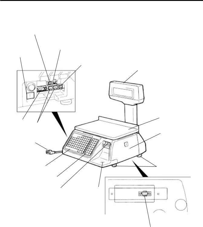
3. APPEARANCE
3. APPEARANCE
LAN I/F
(SL-9000N Option)
PC-AT Keyboard I/F (Option)
Main Power Switch
Drawer I/F (Unused)
CMT/PL-3 I/F
LON I/F
Power Cord
Speed Keyboard and
Programming Keyboard
Operation Keyboard
Print Head |
Level Gauge |
Remote Display
Meat Platter
Right Cover
Adjustable Legs
TMCC I/F: MALE (Option)
3-1

4. DISPLAY
EM1-31064
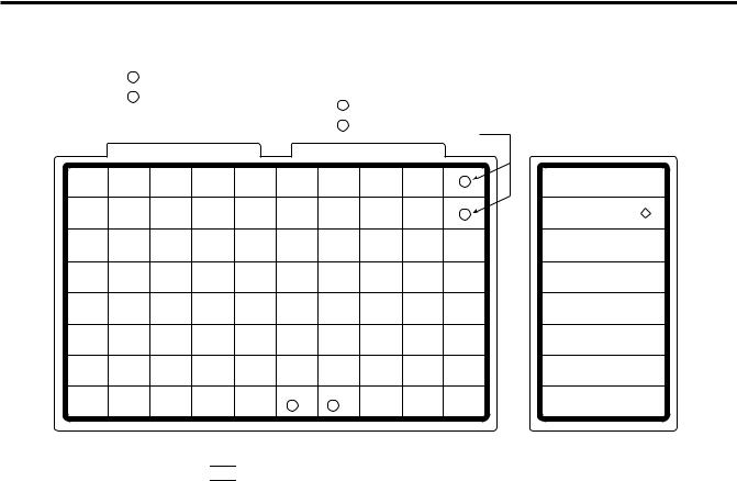
4.1 US TYPE
4. DISPLAY
4.1US TYPE
SL-9000N
CAPACITY |
WEIGHT |
e=d |
SCROLLING MESSAGE INDICATES |
|
0 ~ 15 lb |
0.005 lb |
SCALE AT ZERO |
|
15 ~ 30 lb |
0.01 lb |
|
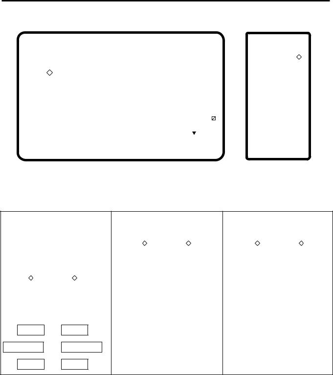
4.2 CA/QR TYPE
SL-9000N |
CAPACITY |
WEIGHT |
e=d |
WEIGHT |
e=d |
|
0 ~ 6 Kg |
0.002 Kg |
0 ~ 15 lbs |
0.005 lbs |
|||
CAPACITÉ |
||||||
|
6 ~ 15 Kg |
0.005 Kg |
15 ~ 30 lbs |
0.01 lbs |
NOTE: For the SL-9000 model, the model name on the display panel is "SL-9000".
4-1
5. KEY LAYOUT
EM1-31064
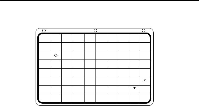
5.1 PROGRAMMING KEYBOARD
5. KEY LAYOUT
5.1 PROGRAMMING KEYBOARD
CLEAR SHIFT
SET NEXT AUTO
NEXT PLU CODE
|
|
|
SEND |
RECEIVE |
− |
PROG. |
|
ENTER |
- |
TEST |
← |
! |
" |
# |
$ |
% |
& |
1 |
2 |
3 |
4 |
5 |
6 |
* |
+ |
( |
) |
/ |
: |
Q |
W |
E |
R |
T |
Y |
[ |
\ |
] |
ˆ |
- |
{ |
A |
S |
D |
F |
G |
H |
È |
É |
 |
Ê |
→ |
← |
Z |
X |
C |
V |
B |
N |
↓ |
CHANGE |
DELETE |
RETURN |
|
PLU |
PLU |
1/4 |
||
|
||||
→ |
DELETE |
INSERT |
DELETE |
|
(A) |
||||
|
1/2 |
1 |
(B) |
|
´ |
` |
? |
@ |
|
7 |
8 |
9 |
0 |
|
; |
< |
= |
> |
|
U |
| |
O |
P |
|
-- |
} |
~ |
|
|
J |
K |
L |
- |
|
↓ |
− |
|
> |
|
M |
SPACE |
, |
. |
ZERO FEED
NOTE: Blank keys have no function.

 Programming Keyboard Function
Name of Key |
Function |
||
|
|
|
|
|
|
|
1. Clears numeric data just entered. |
|
CLEAR |
|
|
|
|
2. Releases the scale from the error mode. |
|
|
|
|
|
|
|
|
|
|
|
|
Selects the upper case or lower case. |
|
SHIFT |
|
|
|
|
|
|
|
|
|
|
|
|
|
|
|
|
|
Calls the PLU # which follows the currently called PLU #. |
|
SET |
|
|
|
NEXT |
|
Sets the media transarency on the sensor. |
|
|
|
|
|
|
Calls the PLU # registered right after the currently called PLU #. |
|
|
NEXT |
|
|
|
PLU |
|
|
|
|
|
|
|
|
Sets "AUTO CODE." |
|
|
AUTO |
|
|
|
CODE |
|
|
|
|
|
|
|
|
Changes the PLU # currently called. |
|
|
CHANGE |
|
|
|
PLU |
|
|
|
|
|
|
|
|
Deletes PLU. |
|
|
DELETE |
|
|
|
PLU |
|
|
|
|
|
|
|
|
|
Prints the data in the currently called PLU. |
|
TEST |
|
|
|
|
|
|
|
|
|
|
|
|
|
|
|
|
|
Inputs data to the SL-9000 system during programming. |
|
ENTER |
|
|
|
|
|
|
|
|
|
|
|
|
|
|
5-1

5. KEY LAYOUT
EM1-31064
5.1 PROGRAMMING KEYBOARD
Name of Key |
|
Function |
||
|
|
|
|
|
|
|
|
1. |
Displays the preceding PLU data. |
|
_ |
|
2. |
Used for setting an auto code. |
|
|
|
3. |
Calls the preceding label format # when setting the print position. |
|
|
|
|
|
|
|
|
Moves the cursor to the left. |
|
|
← |
|
||
|
|
|
|
|
|
|
|
|
|
|
|
|
|
|
|
|
|
Moves the cursor to the right. |
|
|
→ |
|
||
|
|
|
|
|
|
|
|
|
|
|
|
|
|
|
|
|
|
1. |
Deletes the character selected by the cursor when setting commodity |
|
DELETE |
|
||
|
(A) |
|
|
name or message. |
|
1/2 |
|
2. |
Sets a unit price per 1/2 lb. |
|
|
|
||
|
|
|
|
|
|
|
|
1. |
Inserts a space at the cursor position when setting a commodity name or |
|
INSERT |
|
||
|
1 |
|
|
message. |
|
|
|
2. |
Sets a unit price per lb/100g/Kg. |
|
|
|
|
|
|
|
|
Deletes all characters on the selected line when setting commodity name or |
|
|
DELETE |
|||
(B)message.
|
RETURN |
1. |
Displays the next line when setting the ingredient or message. |
|
1/4 |
2. |
Sets a unit price per 1/4 lb. |
|
|
|
|
|
|
Inserts a blank space in descriptors. |
|
|
− |
||
|
SPACE |
|
|
|
|
|
|
|
|
|
|
|
|
Stores "Ingredient data" in the temporaty memory. |
|
|
SEND |
||
|
|
|
|
|
|
|
|
|
|
|
|
|
|
Calls "ingredient data" from the temporaty memory. |
|
|
RECEIVE |
||
|
|
|
|
|
|
|
|
−Sets the preceding item when setting PLU and nutrition information.
↓Sets the following item when setting PLU and nutrition information.
|
PROG. |
|
Returns to the programming menu. |
|
|
|
|
|
|
|
|
|
|
|
|
|
|
|
|
|
|
|
1. |
Selects programming menu page. |
|
|
|
2. |
Selects capitals or small letters. |
|
|
|
3. |
Sorts the file when setting PLU data, ingredient data and nutrition data. |
|
|
|
4. |
Sets a block PLU # using the confirmation label procedure. |
|
|
|
5. |
Selects the scrolling message or fixed message. |
|
|
|
6. |
Calls the second half of the speed key and sets a department #. |
|
|
|
7. |
Selects the adjusting item of print format (in rotation). |
|
|
|
8. |
Toggles between In-line and Local or in-line and off-line of LON system. |
|
|
|||
Other Keys |
The other 39 keys are used to set the character. |
|||
5-2
5. KEY LAYOUT
EM1-31064
5.2 OPERATION KEYBOARD AND SPEED KEYBOARD
5.2 OPERATION KEYBOARD AND SPEED KEYBOARD
|
1 |
Primary function |
|
|
|
US type |
|
CA, QR |
|
|
|
|
|
|
||
|
|
Secondary function |
|
|
|
type |
|
|
|
|
|
|
||||
|
2 |
|
|
|
|
|
|
|
|
|
|
|||||
|
|
1 |
1/2 |
|
100 g |
|
|
|
|
|
|
|||||
|
|
|
|
|
|
|
|
|
|
|
|
|
||||
|
|
|
|
|
|
2 |
1/4 |
|
LB/kg |
|
|
|
|
|
|
|
|
|
|
|
|
|
|
|
|
|
|
|
|
|
|
|
|
1 |
2 |
3 |
4 |
5 |
6 |
7 |
8 |
9 |
1 |
|
ESC. |
|
PROG. |
|
POWER |
|
|
|
|
||||||||||||||
|
|
|
|
|
|
|
|
|
|
|
|
|
||||
10 |
11 |
12 |
13 |
14 |
15 |
16 |
17 |
18 |
2 |
|
NEXT |
|
VOID |
|
|
|
|
|
|
|
|
|
|
|
|
|
|
PLU |
|
|
|
||
|
|
|
|
|
|
|
|
|
|
|
|
|
|
|
|
|
19 |
20 |
21 |
22 |
23 |
24 |
25 |
26 |
27 |
PRESET |
SAVE |
|
FOR |
|
DT/TM |
||
|
|
|
|
|
|
|
|
|
|
COUNT |
|
|
||||
|
|
|
|
|
|
|
|
|
|
|
|
|
|
|
||
28 |
29 |
30 |
32 |
32 |
33 |
34 |
35 |
36 |
GRADE |
7 |
|
8 |
|
9 |
||
|
|
|
|
|
|
|
|
|
|
LINE |
|
|
||||
|
|
|
|
|
|
|
|
|
|
|
|
|
|
|
||
37 |
38 |
39 |
40 |
41 |
42 |
43 |
44 |
45 |
LOGO |
4 |
|
5 |
|
6 |
||
|
|
|
|
|
|
|
|
|
|
|
|
|||||
46 |
47 |
48 |
49 |
50 |
51 |
52 |
53 |
54 |
GROUP# |
1 |
|
2 |
|
3 |
||
55 |
56 |
57 |
58 |
59 |
60 |
61 |
62 |
63 |
ST |
0 |
|
T |
|
C |
||
|
|
|
|
|
|
|
|
|
|
|
|
|||||
64 |
65 |
66 |
67 |
68 |
69 |
70 |
|
|
|
|
|
|
|
|
|
|
ZERO |
TEST |
FEED |
PLU |
|
PRT/* |
|||||||||||
|
|
|
|
|
4 |
3 |
|
|||||||||
|
|
|
|
|
|
|
|
|
|
|
|
|
|
|
|
|
NOTE: 1. The numbers 1~70 indicate the speed key layout, but the actual keys have no number. Pressing the 

 key enables another 70 PLUs assignment.
2.The functions of the 3 and 4 keys can be changed according to the initial settings as follows.
Initial Setting # |
Speed key # |
||||
|
|
|
|||
SL-9000 |
SL-9000N |
SL-9000 |
|||
|
|
||||
|
|
SL-9000N |
|
|
|
8 - 7 |
28 - 4 |
12 - 8 |
69 (4) |
70 (3) |
|
0 |
0 |
0 |
Speed key #69 |
Speed key #70 |
|
|
|
|
|
|
|
0 |
0 |
1 |
Speed key #69 |
AUTO/MANUAL key |
|
|
|
|
|
|
|
1 |
1 |
0 |
Speed key #69 |
Tare % key |
|
1 |
1 |
1 |
AUTO/MANUAL key |
Tare % key |
|
|
|
|
|
|
|

 Operation Keyboard Function
Name of Key |
|
Function |
||||||
|
|
|
|
|
|
|
|
|
|
|
|
|
|
|
|
Enters numeric data such as PLU #, unit price and tare. |
|
|
0 |
to |
9 |
|
||||
|
|
|
|
|||||
|
|
|
|
|
|
|
|
|
|
|
|
|
|
|
|
|
|
|
|
|
|
|
|
|
1. |
Clears numeric entries. |
|
|
|
|
|
|
|
||
|
|
|
C |
|
|
|
2. |
Releases the scale from error mode. |
|
|
|
|
|
|
|
3. |
Releases the scale from SAVE mode. |
|
|
|
|
|
|
|
||
|
|
|
|
|
|
|
|
|
|
|
|
|
|
|
|
Subtracts tare. |
|
|
|
|
T |
|
|
|
||
|
|
|
|
|
|
|
|
|
|
|
|
|
|
|
|
|
|
|
|
|
|
|
|
|
|
|
|
|
|
|
|
|
|
Calls a PLU or clears the displayed PLU. |
|
|
|
|
PLU |
|
|
|
||
|
|
|
|
|
|
|
|
|
|
|
|
|
|
|
|
|
|
|
|
|
|
|
|
|
|
|
5-3

5. KEY LAYOUT
EM1-31064
5.2 OPERATION KEYBOARD AND SPEED KEYBOARD

 Operation Keyboard Function
Name of Key |
Function |
||||
|
|
|
|
|
|
|
|
|
|
|
Prints a customer label. |
|
PRT/* |
|
|||
|
|
|
|||
|
|
|
|
|
|
|
|
|
|
|
|
|
|
|
|
|
Saves tare and unit price after taking off the commodity from the platter. |
|
SAVE |
|
|||
|
|
|
|||
|
|
|
|
|
|
|
|
|
|
|
|
|
|
|
|
|
Sets the quantity of a commodity in "BY COUNT" mode. |
|
FOR |
|
|||
|
|
|
|||
|
|
|
|
|
|
|
|
|
|
|
|
|
|
|
|
|
Displays the date. |
|
DT/TM |
|
|||
|
|
|
|||
|
|
|
|
|
|
|
|
|
|
|
|
|
|
|
|
|
Selects the item for change Print/OFF. |
|
NEXT |
|
|||
|
|
|
|||
|
PLU |
|
|
||
|
|
|
|
|
|
|
|
|
|
|
Corrects data just after the registration. |
|
VOID |
|
|||
|
|
|
|||
|
|
|
|
|
|
|
|
|
|
|
|
|
|
|
|
|
1. Enables calling the other 70 speed keys. |
|
|
|
|
|
|
|
|
|
|
|
2. Selects the function for change Print/OFF. |
|
|
|
|
|
|
|
|
|
|
|
|
|
|
|
|
|
Returns to the main menu. |
|
ESC. |
|
|||
|
|
|
|||
|
|
|
|
|
|
|
|
|
|
|
|
|
|
|
|
|
Accesses print item, auto message timer, print format and issue mode |
|
PROG. |
|
|||
|
|
selection mode. |
|||
|
|
|
|
|
|
|
|
|
|
|
|
|
|
|
|
|
|
|
|
|
|
|
Turns the display on/off when the scale power is on. |
|
POWER |
|
|||
|
|
|
|||
|
|
|
|
|
|
|
|
|
|
|
|
|
|
|
|
|
Changes between 1/2 lb and 1/4 lb (US type only). |
|
1/2 |
|
1/4 |
|
|
|
|
|
|
||
|
|
|
|
|
|
|
|
|
|
|
|
|
100g |
|
Changes the unit of measure to 100g (CA type only). |
||
|
|
|
|||
|
|
|
|
|
|
|
|
|
|
|
|
|
|
|
|
|
Changes the unit of measure between lb and kg (CA type only). |
|
LB/kg |
|
|||
|
|
|
|||
|
|
|
|
|
|
|
|
|
|
|
|
|
|
|
|
|
Sets the number of labels to print. |
|
PRESET |
|
|||
|
COUNT |
|
|
||
|
|
|
|
|
|
|
|
|
|
|
Prints a grade line. |
|
GRADE |
|
|||
|
LINE |
|
|
||
|
|
|
|
|
|
|
|
|
|
|
Calls a logo. |
|
LOGO |
|
|||
|
|
|
|||
|
|
|
|
|
|
|
|
|
|
|
|
5-4

5. KEY LAYOUT
EM1-31064
5.3 SELF SERVICE KEYBOARD
|
Name of Key |
Function |
|||||
|
|
|
|
|
|
|
|
|
|
|
|
|
|
|
No function |
|
|
GROUP |
|
|
|||
|
|
# |
|
|
|
|
|
|
|
|
|
|
|
|
|
|
|
|
|
|
|
|
No function |
|
|
|
ST |
|
|
||
|
|
|
|
|
|
||
|
|
|
|
|
|
|
|
|
|
|
|
|
|
|
|
|
|
|
|
|
|
|
This key is used for item or subtotal discount by entering a percentage. |
|
|
% |
|
|
|
||
|
|
|
|
|
(Optional key by initial setting) |
||
|
|
|
|
|
|
|
|
|
|
|
|
|
|
|
|
|
|
|
|
|
|
|
Feeds the label. |
|
|
FEED |
|
|
|||
|
|
|
|
|
|||
|
|
|
|
|
|
|
|
|
|
|
|
|
|
|
|
|
|
|
|
|
|
|
Issues a test label. |
|
|
TEST |
|
|
|||
|
|
|
|
|
|||
|
|
|
|
|
|
|
|
|
|
|
|
|
|
|
|
|
|
|
|
|
|
|
Adjusts the zero point. |
|
|
ZERO |
|
|
|||
|
|
|
|
|
|||
|
|
|
|
|
|
|
|
|
|
|
|
|
|
|
|
|
|
|
|
|
|
|
Changes the label issue mode between automatic issue and manual |
|
|
AUTO/ |
|
|
|||
|
|
|
|
issue. (Optional key by initial setting) |
|||
|
|
MANUAL |
|
|
|||
|
|
|
|
|
|||
|
|
|
|
|
|
|
|
|
|
|
|
|
|
||
|
1 |
to |
|
70 |
|
Calls the assigned PLU. |
|
|
|
|
|
|
|
||
|
|
|
|
|
|
|
|
|
|
|
|
|
|
|
|
5.3 SELF SERVICE KEYBOARD
1 |
|
2 |
|
3 |
|
X |
X |
X |
X |
||||
|
|
|
|
|
|
|
|
||||||
|
|
|
|
|
|||||||||
|
PUSH |
|
|
PUSH |
|
|
PUSH |
|
X |
X |
X |
X |
|
|
|
|
|
|
|
|
|
|
|
|
|
|
|
|
|
|
|
|
|
|
|
|
|
|
|
|
|
4 |
|
5 |
|
6 |
|
X |
X |
X |
X |
||||
|
|
|
|
|
|
|
|
||||||
|
|
|
X |
|
|||||||||
|
PUSH |
|
|
PUSH |
|
|
PUSH |
|
X |
X |
X |
||
|
|
|
|
|
|
|
|
|
|
|
|
|
|
|
|
|
|
|
|
|
|
|
|
|
|
|
|
7 |
|
8 |
|
9 |
|
X |
X |
X |
X |
||||
|
|
|
|
|
|
|
|
||||||
|
|
|
|
|
|||||||||
|
PUSH |
|
|
PUSH |
|
|
PUSH |
|
X |
X |
X |
X |
|
|
|
|
|
|
|
|
|
|
|
|
|
|
|
C |
0 |
|
PLU |
X |
ZERO |
||||||||
|
|
|
|||||||||||
|
|
||||||||||||
|
PUSH |
|
|
PUSH |
|
|
PUSH |
|
|
PUSH |
|
X |
FEED |
|
|
|
|
|
|
|
|
|
|
|
|
|
|
ESC. |
|
X |
POWER |
|
|
|
|
X |
|
X |
X |
|
|
|
|
X |
|
X |
X |
|
|
|
|
X |
|
X |
X |
|
|
|
|
X |
|
X |
X |
|
|
|
|
X |
|
X |
X |
|
|
|
|
X |
|
X |
X |
|
|
|
|
|
X |
X |
|
|
|
|
|
|
|
|
|
NOTES: 1. When using the self service keyboard, set the initial setting #13-2 to 1.
2.The above X columns indicate No Function.
3.The ESC. key is available while scanning.
5-5
5. KEY LAYOUT
(For Programming/Unit-Price Change/Read Reset/Security)
|
|
|
|
|
CLEAR |
SHIFT |
SET |
NEXT |
AUTO |
|
|
|
|
|
NEXT |
PLU |
CODE |
||
|
|
|
|
|
|
|
|||
|
|
|
|
|
|
|
|
|
|
|
|
|
SEND |
RECEIVE |
− |
↓ |
CHANGE |
DELETE |
RETURN |
|
|
|
PLU |
PLU |
1/4 |
||||
|
|
|
|
|
|
|
|||
|
|
|
|
|
|
|
|
|
|
PROG. |
|
ENTER |
- |
TEST |
← |
→ |
DELETE |
INSERT |
DELETE |
|
(A) |
||||||||
|
1 |
(B) |
|||||||
|
|
|
|
|
|
|
1/2 |
||
! |
" |
# |
$ |
% |
& |
´ |
` |
? |
@ |
1 |
2 |
3 |
4 |
5 |
6 |
7 |
8 |
9 |
0 |
|
|
|
|
|
|
|
|
|
|
* |
+ |
( |
) |
/ |
: |
; |
< |
= |
> |
Q |
W |
E |
R |
T |
Y |
U |
| |
O |
P |
|
|
|
|
|
|
|
|
|
|
[ |
\ |
] |
ˆ |
- |
{ |
-- |
} |
~ |
|
A |
S |
D |
F |
G |
H |
J |
K |
L |
- |
|
|
|
|
|
|
|
|
|
|
È |
É |
 |
Ê |
→ |
← |
↓ |
− |
|
> |
Z |
X |
C |
V |
B |
N |
M |
SPACE |
, |
. |
|
|
|
|
|
|
|
|
|
|
|
|
|
|
|
|
|
ZERO |
|
FEED |
|
|
|
|
|
|
|
|
|
|
EM1-31064
5.3 SELF SERVICE KEYBOARD
ESC. |
PROG. |
POWER |
|
|
|
|
|
|
|
NEXT |
VOID |
|
|
|
PLU |
|
|
|
|
|
|
|
|
|
SAVE |
FOR |
DT/TM |
|
|
|
|
|
|
|
7 |
8 |
9 |
|
|
|
|
|
|
|
4 |
5 |
6 |
|
|
|
|
|
|
|
1 |
2 |
3 |
|
|
|
|
|
|
|
0 |
T |
C |
|
|
|
|
|
|
|
PLU |
PRT/* |
|
||
|
|
|
|
|
The Speed keys can operate among unit-price change (prog-mode), read/reset-mode, security-mode. Of course panel-keys can operate, those panel keys aren't indicated on top of the key-sheet.
|
Unit-Price Change |
|
Read/Reset |
|
Security |
|||||||||||||||||||
(left side key) |
|
(right side key) |
(left side key) |
|
(right side key) |
(left side key) |
|
(right side key) |
||||||||||||||||
|
|
|
= |
|
|
|
|
|
|
= |
|
|
|
|
|
|
|
|
= |
|
|
|
|
|
|
PROG. |
|
|
PROG. |
|
|
|
|
|
|
|
|
|
|
|
|
|
|
|
|
|
|||
|
|
|
|
|
= |
|
|
|
|
|
|
|
|
= |
|
|
|
|
|
|||||
|
0 ~ 9 |
= |
0 ~ 9 |
|
|
0 ~ 9 |
|
|
0 ~ 9 |
|
|
0 ~ 9 |
|
|
|
|
0 ~ 9 |
|
|
|
||||
|
|
|
|
|
|
|
|
|
|
|
|
|
|
|
|
|
|
|
|
|
|
|
|
|
|
|
|
|
|
|
|
|
|
|
|
|
|
|
|
|
|
|
|
|
|
|
|
|
|
|
|
|
= |
|
|
|
NEXT PLU |
|
= |
|
FOR |
|
|
CLEAR |
|
|
= |
|
C |
|
||||
|
|
|
= |
|
|
|
|
|
|
= |
|
|
|
|
|
|
|
|
= |
|
|
|
|
|
|
|
|
|
|
|
|
|
|
|
|
|
|
|
|
|
|
|
|
|
|||||
|
ENTER |
|
|
PRT/* |
|
|
ENTER |
|
|
PRT/* |
|
|
ENTER |
|
|
PRT/* |
|
|
||||||
|
|
|
|
|
|
|
|
|
|
|
|
|
|
|
|
|
|
|
|
|
|
|
|
|
|
|
|
|
|
|
|
|
|
|
|
|
|
|
|
|
|
|
|
|
|
|
|
||
|
CLEAR |
|
= |
|
C |
|
|
|
|
|
|
|
|
NEXT PLU |
|
= |
|
NEXT PLU |
|
|||||
-= VOID
NEXT PLU = NEXT PLU
TEST = TEST
NOTE: If you would like to switch the initial setting #13-2 to 1, please contact your authorized TOSHIBA TEC representative.
5-6

6. PROCEDURE BEFORE OPERATION
EM1-31064
6. PROCEDURE BEFORE OPERATION
6.PROCEDURE BEFORE OPERATION
1.Unpack the accessories and scale from the carton.
2.Install the remote display on the scale. (See Page 7-1.)
3.Refer to Safety Precautions in this manual and set up the scale in a proper location.
4.Load the label or receipt. (See Page 9-1.)
5.Be sure to insert the power cord plug into an AC outlet.
6.Adjust the level gauge. (See page 8-1.)
7.Connect a PC-AT keyboard if necessary.
8.Turn the power on and then press the power key. (See page10-1.)
9.Set the following program menus:
Menu Page |
ITEM No. |
Programming Name |
|
|
|
2 |
0 |
PRINT FORMAT |
2 |
1 |
DATE/TIME SETTING |
1 |
1 |
PLU DATA SETTING |
|
|
|
If necessary, set the following program menus:
Menu Page |
ITEM No. |
Programming Name |
|
|
|
1 |
2 |
INGREDIENT MESSAGE |
1 |
3 |
NUTRITION SETTING |
1 |
5 |
ADDRESS AND COMMERCIAL |
|
|
MESSAGE SETTING |
1 |
7 |
SPECIAL INFORMATION |
1 |
8 |
GRADE LINE |
1 |
9 |
SPEED KEY SET |
|
|
|
10.Call a PLU which contains the unit price used in weighing mode, then place a weight on the platter and check a correct price is displayed.
11.The scale is ready to issue labels.
6-1
7. INSTALLATION PROCEDURE
EM1-31064
7. INSTALLATION PROCEDURE
7. INSTALLATION PROCEDURE

 Remote Display
WARNING!
Be sure to cover the connectors with the connector cover because of high voltage and current. If the connectors are exposed to water, a leakage may result.
CAUTION: Never place the scale upside down. Doing so will cause a malfusction.
1.To install the remote display, insert the two screws provided on the bottom of the remote pipe into the holes in the scale base.
2.Connect the connectors, pull down the connector cover, and install the remote blind plate. Then tighten the screws to secure the remote display.
3.Remove the tape from the remote packing and remote cap and lower to fit them to the scale.
Remote Display |
Screw |
Remote Blind Plate |
|
||
|
|
Remote Pipe
Remote Cap
Remote Packing
Connector
Hole
Tape
Screw
Connector
Connector Cover
7-1
8. LEVEL ADJUSTMENT
EM1-31064
8. LEVEL ADJUSTMENT
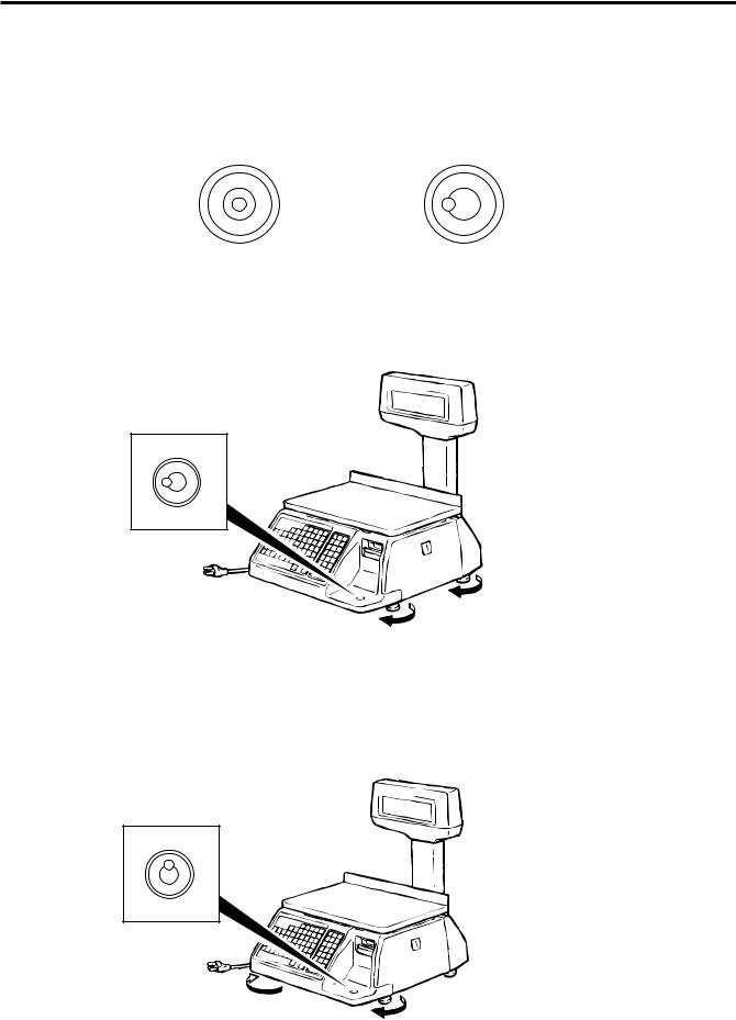
8.LEVEL ADJUSTMENT
1.Level Gauge
Set the scale on a stable and level surface. Level the scale by turning the adjustable legs so that the air bubble is inside the center circle.
Correct |
Incorrect |
2.Adjustment Procedure
1 When the air bubble moves toward the left side, turn the right adjustable legs clockwise.
2 When the air bubble moves toward rear, turn the front adjustable legs clockwise.
8-1

9. REMOVAL AND REPLACEMENT OF MEDIA
EM1-31064
9. REMOVAL AND REPLACEMENT OF MEDIA
9. REMOVAL AND REPLACEMENT OF MEDIA
WARNING!
Since there is a cutter at the paper outlet, be careful not to injure your fingers when replacing media.
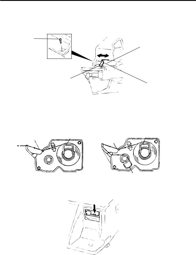
CAUTION: Do not hold the label cassette by the portion A. Doing so may deform the label cassette, causing damage when setting it in position. Please be sure to hold the label cassette as the following figure shows.
A

1.Open the right cover. Then push the head-up lever in the direction indicated by the arrow.
Head-up Lever
2.Pull out the label cassette.
3.Pull out the roll stopper and the backing paper stopper, and remove the media core with backing paper.
Label Cassette
Roll Stopper
Backing Paper Stopper
Backing Paper
NOTE: When removing the backing paper, loosen the paper by turning the paper winding shaft counterclockwise.
9-1
9. REMOVAL AND REPLACEMENT OF MEDIA
EM1-31064
9. REMOVAL AND REPLACEMENT OF MEDIA
4.Loosen the P-2.6x6 screw and move the label guide plate according to the media width.
5.Secure the label guide plate with the P-2.6x6 screw.
Screw (P-2.6x6)
48-mm label dowel
Label Guide Plate
57-mm label dowel
NOTE: Ensure that the label guide plate aligns with the dowel.
6.Refer to the figure below and set the media on the label cassette.
7.Insert the roll stopper into the media core fully.
8.Set the backing paper stopper in the proper orientation.
Label or Report Paper |
Roll Stopper |
Roll Stopper |
|
||
|
Label |
|
|
|
Backing Paper Stopper
9.Set the label cassette to the scale and remove slack of the media. Push down the print head, and close the right cover.
NOTE: After replacing the media, press the feed key to confirm that the media is issued correctly.
*Use of other model’s label cassette in the SL-9000 may cause a label skew.
9-2
10. OUTLINE OF OPERATION
EM1-31064
10. OUTLINE OF OPERATION
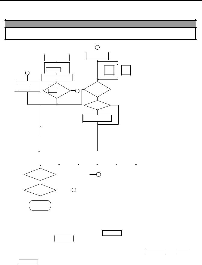
10. OUTLINE OF OPERATION
WARNING!
Since there is a cutter at the paper outlet, be careful not to injure your fingers when issuing labels.
Main Power |
|
2 |
|
|||
Switch ON |
|
|
||||
|
|
|
|
|
||
|
|
|
|
|
|
|
|
|
|
|
Main Menu |
|
|
Display OFF |
|
|
||||
|
|
|
|
|||
|
Press the |
|
|
NEXT |
|
|
1 |
POWER key |
|
|
or |
VOID |
|
|
|
|
PLU |
|
Decrement |
|
|
Scanning Display |
|
|
Increment |
||
|
|
|
|
|
|
|
Press the |
NOTE4 |
|
Menu |
|
|
|
POWER key |
Press |
#1 |
Select the |
|
|
|
|
ESC Key |
2 |
|
Menu # |
|
|
|
No Press |
|
|
Other than Menu #1. |
||
|
|
|
|
Unnecessary |
||
|
|
|
|
Password |
||
|
|
|
|
|
|
|
|
|
|
Necessary |
|
|
|
|
|
|
|
Password Input |
|
|
|
|
|
|
|
|
|
Menu No. 1 |
|
|
|
|
|
Menu No. 2 |
|
|
|
|
|
Menu No. 5 |
|
|
|
Menu No. 4 |
|||||||||||
|
|
|
|
|
|
|
|
MARK DOWN |
|
|
|
|
READ Menu |
|
|
SECURITY |
|
|||||||||||||||||
|
|
|
|
|
|
|
|
|
|
|
|
|
|
|
|
|
|
|
|
|||||||||||||||
|
|
|
REG Menu |
|
|
|
|
|
Menu |
|
|
|
|
(Refer to Section 12, 15) |
|
|
|
Menu |
|
|||||||||||||||
|
|
(Refer to Section 14) |
|
|
|
(Refer to Section 14) |
|
|
|
|
|
|
|
|
|
|
(Refer to Section 13) |
|
||||||||||||||||
|
|
|
|
|
|
|
|
|
|
|
|
|
|
|||||||||||||||||||||
|
|
|
|
|
|
|
|
|
|
|
|
|
|
|
|
|
|
|
|
|
|
|
|
|
|
|
|
|
|
|
|
|
||
|
|
|
|
|
|
|
|
|
|
|
|
Menu No. 3 |
|
|
|
|
|
|
Menu No. 0 |
|
|
|
Menu No. 6 |
|
|
|
||||||||
|
|
|
|
|
|
|
|
|
REWRAP Menu |
|
|
|
PROG Menu |
|
|
RESET Menu |
|
|
|
|
||||||||||||||
|
|
|
|
|
|
|
|
|
|
|
|
|
|
|
|
|
|
|||||||||||||||||
|
|
|
|
|
|
|
|
|
(Refer to Section 14) |
|
|
|
(Refer to Section 11) |
|
|
(Refer to Section 15) |
|
|
|
|
||||||||||||||
|
|
|
|
|
|
|
|
|
|
|
|
|
|
|
|
|
|
|
|
|
|
|
|
|
|
|
|
|
|
|
|
|
|
|
|
|
|
|
|
|
|
|
|
|
|
|
|
|
|
|
|
|
|
|
|
|
|
|
|
|
|
|
|
|
|
|
|
|
|
|
|
|
|
|
|
|
|
|
|
|
|
|
|
|
|
|
|
|
|
|
|
|
|
|
|
|
|
|
|
|
|
|
|
|
|
|
|
|
|
|
|
|
|
|
|
|
|
|
|
|
|
|
|
|
|
|
|
|
|
|
|
|
|
|
|
|
|
||
|
|
|
|
|
|
|
|
|
NOTE5 |
|
|
|
|
|
|
|
|
|
|
|
|
|
|
|
|
|
|
|
|
|
|
|
||
|
|
|
|
|
|
|
|
|
|
|
|
Press |
|
|
|
|
|
|
|
|
|
|
|
|
|
|
|
|
|
|||||
|
|
|
POWER |
|
|
|
key |
|
Display OFF |
|
|
1 |
|
|
|
|
|
|
|
|
|
|
|
|||||||||||
|
|
|
|
|
|
|
|
|
|
|
|
|
|
|
|
|||||||||||||||||||
|
|
No Press |
|
|
|
NOTE5 |
|
|
|
|
|
|
|
|
|
|
|
|
|
|
|
|
|
|
|
|
|
|
|
|||||
|
|
|
|
|
Press |
|
|
|
|
|
|
<Menu> |
|
|
|
|
|
|
|
|
||||||||||||||
|
|
|
|
|
|
|
|
|
|
|
|
|
|
|
|
|
|
|
|
|
|
|
||||||||||||
|
|
|
|
|
|
|
|
|
|
|
|
2 |
|
|
|
|
|
|
|
|
|
|
|
|
||||||||||
|
|
|
|
ESC. |
key |
|
|
|
|
|
|
|
|
|
|
|
|
|
||||||||||||||||
|
|
|
|
|
|
|
|
|
|
|
|
0. |
PROG. |
|
|
5. |
REPORT |
|||||||||||||||||
|
|
No Press |
|
|
|
|
|
|
|
|
|
|
|
|
|
|
|
|
|
|||||||||||||||
|
|
|
|
|
|
|
|
|
|
|
|
|
|
|
|
1. |
REG |
|
|
6. |
RESET |
|||||||||||||
|
|
|
|
|
|
|
|
|
|
|
|
|
|
|
|
|
|
|
|
|
|
|
||||||||||||
|
|
|
|
Return to |
|
|
|
|
|
|
|
|
|
2. |
MARK DOWN |
|
|
7. |
|
|
||||||||||||||
|
|
|
each mode |
|
|
|
|
|
|
|
|
|
3. |
REWRAP |
|
|
8. |
|
|
|||||||||||||||
NOTES: |
|
|
|
|
|
|
|
|
|
4. |
SECURITY |
|
|
9. |
|
|
||||||||||||||||||
|
|
|
|
|
|
|
|
|
|
|
|
|
|
|
|
|
|
|
|
|
|
|
||||||||||||
|
|
|
|
|
|
|
|
|
|
|
|
|
|
|
|
|
|
|
|
|
|
|
||||||||||||
1.You can register a password to prohibit unauthorized access to each menu expect for REG. menu.
2.To avoid wasteful use of the display, press the POWER key to turn the display off while being unused. Pressing the POWER key again allows you to enter REG. mode without scanning.
3.Refer to respective sections for explanation each menu enclosed by a double rectangle.
4.In the self service scale mode (the initial setting #13-2 is set to 1) the POWER , and ESC. keys are available in the following cases.
POWER key: Available after the main power switch turns ON.
ESC. |
key: |
Available after the POWER key is depressed while scaling. |
5.In the self service scale mode (the initial setting #13-2 is set to 1), these keys are unavailable.
If you would like to switch the initial setting #13-2 to 1, please contact your authorized TOSHIBA TEC representative.
10-1
10. OUTLINE OF OPERATION |
EM1-31064 |
|
10. OUTLINE OF OPERATION |
|
|
■ Registration Mode
O:AVAILABLE X:NOT AVAILABLE
No. |
FUNCTION |
WEIGH |
BY |
FIX PRICE |
SELF |
|
COUNT |
SERVICE |
|||
|
|
|
|
||
1 |
ZERO SETTING |
O |
X |
O |
O |
2 |
LABEL FEED |
O |
O |
O |
O |
3 |
CALL PLU BY SPEED KEY |
O |
O |
O |
X |
4 |
CALL PLU BY PLU KEY |
O |
O |
O |
O |
5 |
RETURN TO PLU CALLING MODE |
O |
O |
O |
O |
7 |
TEMPORARY CHANGE OF DATE |
O |
X |
O |
X |
8 |
TARE CLEAR |
O |
X |
O |
X |
9 |
PRESET TARE 1 |
O |
X |
O |
X |
10 |
PRESET TARE 2 |
O |
X |
O |
X |
11 |
DIRECT TARE |
O |
X |
O |
X |
12 |
SAVE UNIT PRICE |
O |
X |
O |
X |
13 |
SAVE TARE |
O |
X |
O |
X |
14 |
TEST PRINT |
O |
O |
O |
X |
15 |
MANUAL ISSUE WITH WEIGHING |
O |
X |
O |
X |
16 |
VOID REGISTRATION |
O |
O |
O |
X |
17 |
AUTO ISSUE WITH WEIGHING |
O |
X |
O |
X |
18 |
1/2, 1/4LB KEY |
O |
X |
X |
X |
19 |
100g, kg KEY |
O |
X |
X |
X |
20 |
LB/kg KEY |
O |
X |
X |
X |
21 |
CHANGE PRINT/OFF |
O |
O |
O |
X |
22 |
BY COUNT (FIX PRICE) |
X |
O |
X |
O |
23 |
BY COUNT (PRICE/PIECES) |
X |
O |
X |
X |
24 |
BY COUNT (SPLIT PRICE) |
X |
O |
X |
X |
25 |
COUNT PRESET |
O |
O |
O |
X |
26 |
NET WT. STATEMENT |
X |
X |
O |
X |
27 |
CALL LOGO |
O |
O |
O |
X |
28 |
CALL DEPT. # |
O |
O |
O |
X |
29 |
CALL GRADE LINE |
O |
O |
O |
X |
30 |
OPEN PLU |
O |
O |
O |
O |
31 |
AUTO CLEAR |
O |
X |
O/X |
O |
32 |
FLOATING VENDOR |
O |
O |
O |
X |
33 |
% TARE |
O |
X |
X |
X |
34 |
BATCH PRINTING |
X |
O |
O/X |
X |
35 |
VISUAL COMMODITY LIBRARY |
O |
O |
O |
X |
36 |
TMCC (CMT-port) communication |
O |
O |
O |
O |
37 |
Clerk Label |
O |
O |
O |
X |
10-2

11. PROGRAMMING PROCEDURES
EM1-31064

 How to access the Programming Menu
11. PROGRAMMING PROCEDURES

 How to access the Programming Menu
Enter a |
|
unnecessary |
|
||
menu number |
|
|
|
|
|
|
|
|
ESC. |
0 |
Password |
neccesary |
|
Select the |
|
programming |
Select an item No. |
menu Page |
(See next page.) |
Enter the |
0 |
~ |
9 |
|
Password |
||||
|
|
|
Programming |
Programming |
PROG. |
|
starts |
completes |
||
|
NOTES:1. When the selected menu ( 0 ) is protected from an access, refer to Section 13.2 and enter the password.
2.In Sections 11.1, 11.2 and 11.3, items which have been sold on that day cannot be called before resetting (refer to Section 15.) unless Initial Setting #1-4 is set to 1.

 How to Select Menu and Item No.
<Menu> PROG. 1 |
|
|
|
0. |
PLU DATA EDIT |
5. |
MESSAGE |
1. |
PLU DATA |
6. |
MSG. COMBINATION |
2. |
INGREDIENT |
7. |
SPECIAL INFO |
3. |
NUTRITION |
8. |
GRADE LINE |
4. |
CONFIRMATION LABEL |
9. |
SPEED KEY SET |
|
|
|
|
<Menu> PROG. 2 |
|
|
|
0. |
PRT LOCATION |
5. |
INITIAL SET |
1. |
DATA TIME |
6. |
BAR CODE FORMAT |
2. |
CMT |
7. |
TITLE |
3. |
ON-LINE/LOCAL |
8. |
LOGO |
4. |
LON SYSTEM |
9. |
IDIOM |
|
|
|
|
<Menu> PROG. 3
0.VENDOR
1.FREE FORMAT
2.LAN SYSTEM (SL-9000N only)
11-1

11. PROGRAMMING PROCEDURES
EM1-31064

 How to access the Programming Menu

 Table 1: Title and Contents of Programming Menu
NO. |
TITLE |
MENU |
ITEM |
CONTENTS |
Page |
|
|
Page |
No. |
|
|
1 |
PLU DATA EDIT |
1 |
0 |
CHANGE UNIT PRICE |
11-4 |
|
|
|
|
|
|
2 |
PLU DATA |
1 |
1 |
PROGRAM/CHANGE/DELETE PLU |
11-5 |
3 |
INGREDIENT MESSAGE |
1 |
2 |
PROGRAM/CHANGE INGREDIENT |
11-7 |
|
|
|
|
|
|
4 |
NUTRITION FACTS |
1 |
3 |
PROGRAM/CHANGE NUTRITION FACTS TABLE |
11-8 |
|
|
|
|
|
|
5 |
CONFIRMATION LABEL |
1 |
4 |
VERIFY THE PROGRAMMING DATA OF PLU |
11-12 |
|
|
|
|
|
|
6 |
ADDRESS SETTING |
1 |
5 |
PROGRAM MESSAGE/ADDRESS |
11-13 |
|
|
|
|
|
|
7 |
COMBINATION MESSAGE |
1 |
6 |
PROGRAM MESSAGE ON DISPLAY AND TIME |
11-14 |
8 |
SPECIAL INFO. |
1 |
7 |
PROGRAM SPECIAL INFORMATION |
11-16 |
|
|
|
|
|
|
9 |
GRADE LINE |
1 |
8 |
PROGRAM GRADE LINE |
11-16 |
|
|
|
|
|
|
10 |
SPEED KEY SETTING |
1 |
9 |
ASSIGN COMMON PLU TO SPECIFIC SPEED KEY |
11-17 |
|
|
|
|
|
|
11 |
PRT LOCATION |
2 |
0 |
SELECT LABEL FORMAT AND ADJUST |
11-18 |
|
|
|
|
|
|
12 |
DATE/TIME SETTING |
2 |
1 |
PROGRAM DATE/TIME/MACHINE #/STORE CODE |
11-20 |
13 |
CMT/PL-3 |
2 |
2 |
BACK-UP /LOAD DATA OF PLU/ING/NUTRI./SPEED KEY |
11-20 |
|
|
|
|
|
|
14 |
IN-LINE/LOCAL |
2 |
3 |
SET PARAMETERS FOR TMCC |
11-23 |
|
|
|
|
|
|
15 |
LON SYSTEM |
2 |
4 |
SET PARAMETERS FOR LON |
11-24 |
|
|
|
|
|
|
16 |
INITIAL SET |
2 |
5 |
SET INITIAL PARAMETERS |
- |
|
|
|
|
|
|
17 |
BAR CODE FORMAT |
2 |
6 |
PROGRAM BARCODE FORMAT |
11-26 |
18 |
TITLE |
2 |
7 |
PROGRAM/CHANGE TITLE ON DISPLAY/PRINT |
11-28 |
|
|
|
|
|
|
19 |
LOGO |
2 |
8 |
SEND/RECIEVE LOGO DATA |
11-29 |
|
|
|
|
|
|
20 |
IDIOM |
2 |
9 |
PROGRAM IDIOM |
11-30 |
|
|
|
|
|
|
21 |
VENDOR |
3 |
0 |
VENDOR NAME |
11-30 |
|
|
|
|
|
|
22 |
FREE FORMAT |
3 |
1 |
PROGRAM FREE FORMAT |
11-31 |
23 |
LAN SYSTEM |
3 |
2 |
PROGRAMS PARAMETERS FOR LAN |
- |
|
(SL-9000N only) |
|
|
|
|
|
|
|
|
|
|
NOTE: Menu No. 16 and 23 are programs for use of dealers. Contact a TOSHIBA TEC representative if you desire to use them. When you enter one of these menus by mistake, press ESC. key to return to Main Menu.
11-2
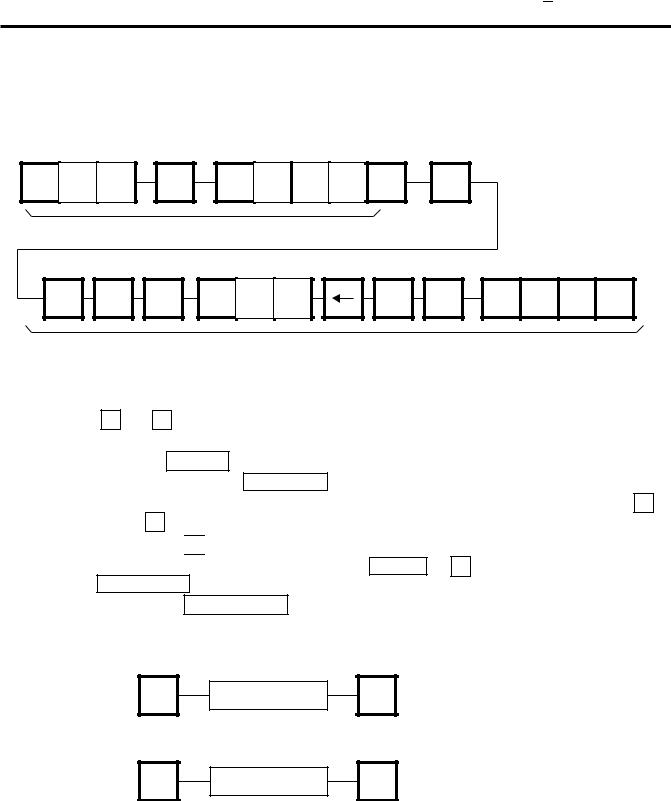
11. PROGRAMMING PROCEDURES
EM1-31064

 How to enter characters

 How to enter characters
Use the following procedure to enter a commodity name, address and ingredient message.
Example) 1st line: |
TEC STORE |
2nd line |
(TEL) 0123-45-6789 |
T E C
SPACE |
S |
T |
O |
R |
E |
RETURN |
1/4 |
1st line content
SHIFT |
( |
SHIFT |
T E E
2nd line content
DELETE
(A) 1/2
L |
6 |
7 |
8 |
9 |
NOTES: 1. ← and → keys are the cursor keys.
2.To insert a space, move the cursor to the next character to the space to be inserted, and press INSERT key.
3.To delete a line, press DELETE (B) key.
4. To move the cursor to the preceding line when entering a commodity name, press - key, or − key.
5.Pressing the 

 key toggles between capitals and small letters.
6.When entering a commodity name, press ENTER or ↓ key instead of the RETURN 1/4 key to return.
7.Pressing the CHANGE PLU key toggles the type font between normal and boldface.
8.To call a preset ingredient message idiom, follow the procedure below:
9.To skip a line when entering an ingredient message, follow the procedure below:
NEXT |
Enter the idiom |
#. |
RETURN |
PLU |
1/4 |
||
|
|
|
SET |
Enter the line |
#. |
RETURN |
NEXT |
1/4 |
||
|
|
|
11-3
Loading...