


-USER MANUAL
-MANUEL DE L’UTILISATEUR
-BENUTZERHANDBUCH
-HANDLEIDING
-MANUALE D’USO
-MANUAL DEL USUARIO
-MANUAL DO UTILIZADOR
-РУКОВОДСТВО ПОЛЬЗОВАТЕЛЯ
-Εγχειρίδιο χρήσης
-Kullanım Kılavuzu
-Instrukcja obsługi
Downloaded from
www . vandenborre . be

FOR XBOX ONE
Downloaded from
www . User Manualvandenborre . be
WARNING:
To ensure that your TX Racing Wheel functions correctly with games for XBOX ONE,
you may be required to install the games' automatic updates
(available when your games console is connected to the Internet).
1/24
TECHNICAL SPECIFICATIONS
Downloaded from
www . vandenborre . be
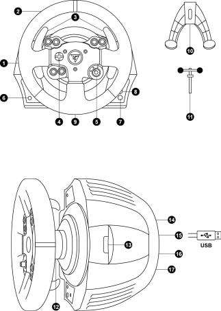
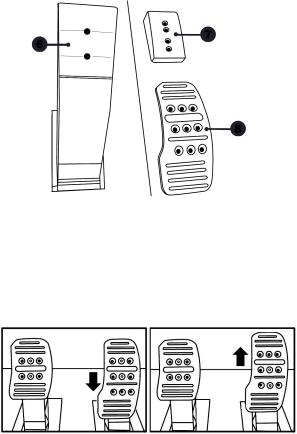
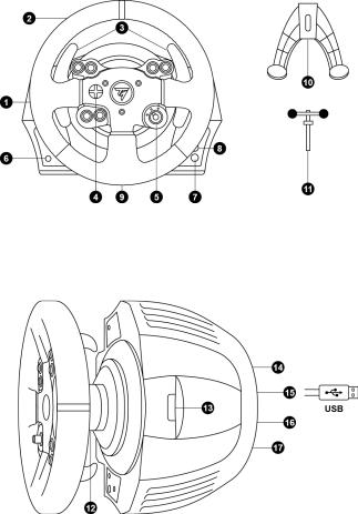
1 |
Racing wheel base |
7 |
Xbox Guide button |
2 |
Racing wheel |
8 |
White indicator light |
3 |
2 sequential gear shift levers (Up & Down) |
9 |
Large threaded hole (for attachment system |
4 |
Multidirectional D-Pad |
|
and tightening screw) |
5 |
Switch (3 positions) |
10 |
Attachment system |
6 |
MODE button + Red/Green indicator light |
11 |
Metal fastening screw |
12 |
Thrustmaster Quick Release |
|
15 |
Racing wheel USB cable and connector |
||
13 |
Controller |
pairing |
(for |
Kinect™ |
16 |
Gearbox connector |
14 |
detection) |
|
|
|
17 |
(sold separately, forthcoming release) |
Mains supply connector (type A or B) |
Pedal set connector |
|||||
(Varies from one country to another)
2/24

|
BEFORE PROCEEDING! |
Downloaded |
|
|
|
|
|
|
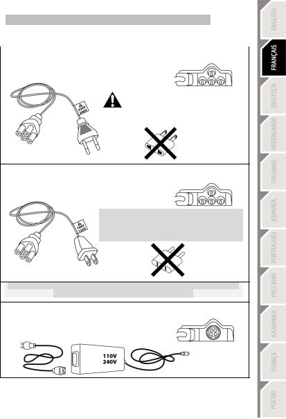
CONNECTING THE RACING WHEEL TO THE MAINS = PLEASE READ |
|
|
||||
|
|
varies according to the country where you purchased your device. |
|||||
|
Your racing wheel's power supply |
||||||
|
The mains supply can be: |
from |
|||||
|
|
www |
|
||||
|
Internal, with: |
|
|
||||
|
* A power supply unit located directly inside the racing wheel's base, with |
. |
|
|
|||
|
a type A |
||||||
|
= compatible only with a 220-240V electrical supply. |
vandenborre |
|||||
|
connector |
|
|
|
|
|
|
*A 220-240V mains power supply cable |
|
|
|
|
|
||
|
|
|
|
. |
|||
|
|
|
|
|
|
|
be |
|
|
|
Never connect the 220-240V cable |
|
|
|
|
|
|
|
to a 100-130V power outlet! |
|
|
|
|
|
|
|
Never connect this cable to a mains power adapter! |
|
|
||
Internal, with:
* A power supply unit located directly inside the racing wheel's base, with a type A connector
*A 100-125V power supply cable
= compatible only with a 100-125V electrical supply.
 Never connect the 100-125V cable to a 220-240V power outlet!
Never connect this cable to a mains power adapter!
IMPORTANT: if you do not know which voltage is supplied in the area in which you are using your racing wheel, please refer to your local electricity supplier.
External, with:
*An external power supply unit located on the racing wheel's base, with a type B connector
*A mains power supply cable
= compatible with all supply voltages, 110-240V.
3/24

WARNINGS |
Downloaded |
|
|
|
|
Before you use this product, please read this documentation carefully and keep it safe shouldfrom you need to |
||
consult it later. |
|
www |
|
|
|
|
|
. |
Warning – Electric shock |
|
vandenborre |
* Store the product in a dry location and do not expose it to dust or sunlight. |
|
|
* Respect the connection direction. |
|
. |
|
|
be |
* Do not twist or pull the connectors and cables.
* Do not spill any liquid on the product or its connectors. * Do not short-circuit the product.
* Never dismantle the product; do not throw it onto a fire and do not expose it to high temperatures. * Do not use a power supply cable other than the one provided with your racing wheel.
* Do not use the mains power supply cable if the cable or the connectors are damaged, split or broken.
* Make sure that the mains power cable is properly inserted into the power outlet and the connector located on the rear face of the racing wheel's base.
* Do not open. No user replaceable parts inside. Refer servicing to manufacturer, specified agency or qualified technician.
* Only use attachments/accessories specified by the manufacturer.
* If the steering wheel is operating unusually (if it is emitting any abnormal sounds, heat or odors), stop using it immediately, disconnect the power cable from the socket and disconnect the other cables.
* If you are not going to be using the steering wheel for an extended period, disconnect the mains adaptor from the wall socket.
 Air vents
Make sure that you do not block any of the air vents on the steering wheel base. For optimum ventilation, respect the points below:
*Position the base at least 10 cm away from any wall surfaces.
*Do not place the base in any tight spaces.
*Do not cover the base.
*Do not let any dust build up on the air vents.
For safety reasons, never use the pedal set with bare feet or while wearing only socks on your feet.
THRUSTMASTER® DISCLAIMS ALL RESPONSIBILITY IN THE EVENT OF INJURY RESULTING FROM USE OF THE PEDAL SET WITHOUT SHOES.
 Warning – Injuries due to force feedback and repeated movements
Playing with a force-feedback steering wheel may cause muscle or joint pain. To avoid any problems:
*Avoid lengthy gaming periods.
*Take 10 to 15 minute breaks after each hour of play.
*If you feel any fatigue or pain in your hands, wrists, arms, feet or legs, stop playing and rest for a few hours before you start playing again.
4/24
Warning – Injuries due to force feedback and repeated movementsDownloaded(suite) |
||
|
from |
|
* If the symptoms or pain indicated above persist when you start playing again, stop playing and |
||
consult your doctor. |
www |
|
* Keep out of children’s reach. |
||
. |
||
* During games, always leave both hands correctly positioned on the steering wheel without completely |
||
letting go. |
|
|
* During gameplay, never place your hands or your fingers under the pedals or anywhere near the |
||
pedal set. |
vandenborre |
|
. |
||
|
be |
|
* During calibration and gameplay, never place your hand or your arm through the openings in the racing wheel.
* Check the steering wheel base is carefully clamped as per manual’s instructions.
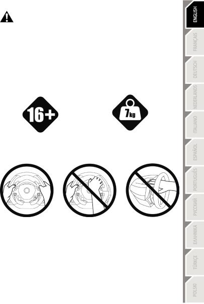
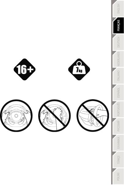
HEAVY PRODUCT
To be handled only by users 16 years of age or older
ALWAYS
Be careful not to drop the product on yourself or on anyone else!
NEVER |
NEVER |
5/24
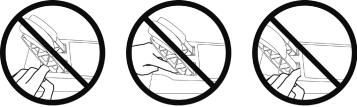
 Warning – Pedal set pinch hazard when playing
Downloaded
* Keep the pedal set out of children’s reach. |
|
|
from |
|
|
* When playing, never place your fingers on or anywhere near the sides of the pedals. |
www |
||||
* When playing, never leave your fingers on or anywhere near the pedals' rear base. |
|
||||
|
|
. |
|||
* When playing, never place your fingers on or anywhere near the pedals' front base. |
|
|
vandenborre |
||
NEVER |
NEVER |
NEVER |
|||
|
|||||
|
|
|
|
. |
|
|
|
|
|
be |
|
 Warning – Pedal set pinch hazard when not playing
* Store the pedal set in a safe place, and keep it out of children’s reach.
6/24
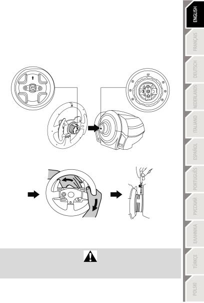
ATTACHING THE WHEEL TO ITS BASE |
Downloaded |
|
Align the connector locations using the arrows: |
|
|
from |
|
|
Base (1) connector: Arrow pointing upwards |
|
|
Racing wheel (2) connector: Arrow pointing upwards |
www |
|
|
|
|
|
. |
|
Once the connectors are correctly positioned, simply rotate the Thrustmaster Quick Release (12) device's |
|
|
ring counterclockwise, while holding the racing wheel (2) in position. |
|
|
Then, tighten the ring as much as you can; to do so, hold the ring in position and rotate the racing wheel |
|
|
clockwise. |
vandenborre |
|
|
. |
|
|
|
be |
Once you have installed the wheel, rotate it 180° (when facing the wheel, the logo should be upside
down) to access the small attachment screw located on the Thrustmaster Quick Release (12) device. Use a large cross-slot screwdriver to tighten the small attachment screw (do not use excessive force), turning it clockwise.
Do not use excessive force when screwing the small attachment screw (using a cross-slot screwdriver)!
Stop turning the screw as soon as you feel some resistance.
7/24
ATTACHING THE RACING WHEEL |
Downloaded |
|
|
Attaching the racing wheel to a table or a desktop |
from |
|
|
|
www |
|
|
1. Place the racing wheel on a table or any other horizontal, flat and stable surface. |
|
||
. |
|
||
2. Insert the fastening screw (11) in the attachment system (10), then tighten the device by turning |
|
||
the screw counterclockwise, so that it feeds into the large threaded hole (9) located beneath the |
|
||
racing wheel, until the device is perfectly stable. |
|
vandenborre |
|
|
|
||
|
|
|
. |
ALWAYS |
NEVER |
|
be |
|
|
||
WARNING: Never tighten the screw alone, without the attachment system!
(This could damage the racing wheel).
8/24

ATTACHMENT /
REMOVAL
To tighten:
Turn the screw counterclockwise
To release:
Turn the screw clockwise
DIRECTION
Downloaded from
www . vandenborre . be
9/24
Attaching the racing wheel's base to a cockpit |
Downloaded |
|
|
|
1. |
Place the racing wheel's base on the cockpit shelf. |
|
|
|
2. |
Drive two M6 screws (not included) through the cockpit shelf, then feed them into thefromtwo small |
|
||
|
threaded holes located beneath the racing wheel. |
|
|
|
|
Important: The length of the M6 screws should not exceed the thickness of the shelf + www12 mm; |
|
||
|
longer screws could cause damage to internal components located in the racing wheel's base. |
. |
|
|
3. |
|
|
||
If required, tighten the standard attachment system by inserting the fastening screw in the large |
|
|||
|
threaded hole. |
|
vandenborre |
|
|
|
|
||
|
|
|
|
. |
XBOX ONE MAPPING |
|
|
be |
|
|
|
|
||
10/24

UPGRADING YOUR RACING WHEEL'S FIRMWARE |
Downloaded |
|
|
|
|
The firmware included in your racing wheel's base can be upgraded to a more recent version featuring |
|
|
product enhancements. |
from |
|
www |
|
|
|
|
|
|
. |
|
To display the firmware version that your racing wheel is currently running and upgrade it if required: |
|
|
on PC, connect to http://ts.thrustmaster.com. In the Updates and downloads section, click Xbox |
|
|
One / Wheels / TX Racing Wheel, then select Driver / Firmware and follow the instructions |
|
|
describing the download and setup procedure. |
vandenborre |
|
|
||
|
|
. |
SETTING UP THE RACING WHEEL FOR THE XBOX ONE |
be |
|
|
||
1.Connect the pedal set to the connector (17) located at the back of the racing wheel's base.
2.Connect the power supply cable to the connector (14) located at the back of the racing wheel's base.
3.Connect the power supply cable to a mains outlet with proper voltage specifications.
For more information about this, please refer to the CONNECTING THE RACING
WHEEL TO THE MAINS section, on page 3 in this manual.
4. Connect the racing wheel's USB connector (15) to one of the console's USB ports.
You are now ready to race!
AUTOMATIC RACING WHEEL AND PEDAL SET CALIBRATION
The racing wheel automatically self-calibrates when you connect the racing wheel to the mains and the racing wheel's USB connector to the console.
During this phase, the racing wheel will rotate quickly towards the left and the right, covering a 900 degree angle, before stopping at the center.
WARNING:
Never touch the racing wheel during the self-calibration phase!
(This could cause an incorrect calibration and/or personal injuries).
AUTOMATIC CALIBRATION OF THE PEDAL SET
Never connect the pedal set to the racing wheel's base (or disconnect it from the base) when it is connected to the console or during gameplay (this could cause incorrect calibration).
Always connect the pedal set before connecting the racing wheel to the console.
Once the racing wheel's calibration is done and the game has been launched, the pedals are automatically calibrated after a few presses.
WARNING: Never press the pedals
during the racing wheel's self-calibration phase or while a game is loading!
(This could cause incorrect calibration)
11/24
If your racing wheel and pedal set do not operate correctly, or if calibration seems incorrect: |
||
Downloaded |
|
|
Turn off your console, disconnect your racing wheel entirely, reconnect all cables (using the mains |
||
power supply cable and pedal set), then restart your console and your game. |
from |
|
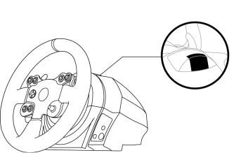
CONTROLLER PAIRING (13) |
www |
|
|
. |
|
To ensure correct detection of your racing wheel, the device's controller pairing (located on the upper |
||
section of the racing wheel's base) must always remain in the KINECT™ camera's field of vision. |
vandenborre |
|
|
|
|
|
|
. |
|
|
be |
INTERNAL TEMPERATURE SENSOR
For safety reasons, the racing wheel's base features a temperature sensor.
If the device's temperature becomes too high, your racing wheel can shut down suddenly. In this event:
-Unplug the mains power supply cable and the device's USB connector.
-Wait for the racing wheel's base to cool down entirely.
-Then, reconnect the device.
12/24

|
MODE BUTTON AND INDICATOR LIGHT (6) |
Downloaded |
|
|
|
|
|
MODE button for the pedal set |
|
|
|
|
|
|
|
from |
|
|||
|
You can electronically swap the accelerator and clutch pedals. |
|
||||
|
|
www |
|
|||
|
To do so, simply press the MODE button (6) for 2 seconds. |
|
|
|||
|
|
|
|
|
||
|
The racing wheel's internal memory stores whether the pedals have been swapped around or not.. |
|
||||
|
|
|
|
vandenborre |
||
|
ACCELERATOR AND CLUTCH PEDALS |
Color of the MODE indicator light (6) |
|
|||
|
NORMAL |
|
RED |
|
||
|
|
|
|
. |
||
|
|
|
|
|
|
be |
|
SWAPPED AROUND |
|
GREEN |
|
|
|
|
|
|
|
|
||
Other hints for the MODE button
To learn more about MODE button and indicator light, please visit http://ts.thrustmaster.com; in the
Updates and downloads section, click Xbox One / Wheels / TX Racing Wheel, then select Manual / Help file.
HELP FILES AND FAQS (not stated in this manual)
Please access http://ts.thrustmaster.com; in the Updates and downloads section, click Xbox One / Wheels / TX Racing Wheel, then select Manual / Help file.
13/24

Downloaded from
www . vandenborre . be
14/24
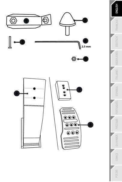
TECHNICAL FEATURES
Downloaded from
www . vandenborre . be
1 Metal support for conical stop |
4 |
2.5 mm Allen key (included) |
(not installed by default) |
5 |
Position adjustment nut for conical stop |
2Conical stop
3Attachment screw for metal support
6 |
Pedal arm |
8 Metal pedal head |
7 |
Plastic head support |
|
15/24
WARNING |
Downloaded |
|
|
|
|
|
|
Before using this product, be sure to read these instructions carefully and save them for future reference. |
|
||
|
from |
|
|
|
www |
|
|
|
|
. |
|
For safety reasons, never use the pedal set with bare feet or while wearing |
vandenborre |
||
|
only socks on your feet. |
|
|
THRUSTMASTER® DISCLAIMS ALL RESPONSIBILITY IN THE EVENT OF |
|
|
|
|
INJURY RESULTING FROM USE OF THE PEDAL SET WITHOUT SHOES. |
|
. |
|
|
|
be |
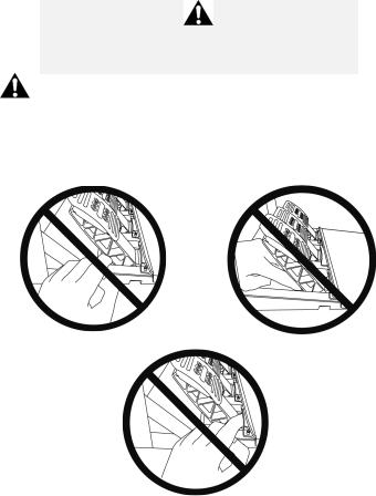
Warning – Pedal set pinching hazard during gaming sessions
*Keep the pedal set out of the reach of children.
*During gaming sessions, never place your fingers or thumbs on or near the sides of the pedals.
*During gaming sessions, never place your fingers or thumbs on or near the rear base of the pedals.
*During gaming sessions, never place your fingers or thumbs on or near the front base of the pedals.
NEVER |
NEVER |
NEVER
16/24

AUTOMATIC CALIBRATION OF PEDALS |
Downloaded |
|
|
|
|
|
|
|
from |
|
|
IMPORTANT: |
www |
|
|
|
|
. |
|
- Never connect or disconnect the pedal set from the base of the wheel when the wheel is |
|
||
connected to the console or PC, or during gaming sessions, to avoid calibration problems. |
vandenborre |
||
= Always connect the pedal set to the wheel before connecting the wheel to the console or PC. |
|||
|
|
||
- Once the wheel has self-calibrated and the game has started, the pedals automatically calibrate |
. |
||
be |
|||
themselves after being pressed a few times. |
|
|
|
-Never press on the pedals when the wheel is self-calibrating or when your game is starting up, to avoid calibration problems.
-If the pedals are not functioning correctly or appear to be improperly calibrated, power off your console, completely disconnect your wheel, then reconnect all of the cables (including the power supply cable and the pedal set cable), power the console back on and restart your game.
ATTACHING THE PEDAL SET TO A COCKPIT
-Attach the pedal set using the small screw threads located on the underside of the pedal set.
-Screw two M6 screws (not included) into the cockpit’s pedal support plate and into the two small screw threads located on the underside of the pedal set.
Important: The length of the two M6 screws must not exceed the thickness of the cockpit’s pedal support plate plus an additional 10 mm, to avoid damaging the pedal set’s internal components.
17/24
ADJUSTING THE PEDAL SET |
Downloaded |
|
|
Each of the three pedals includes: |
|
||
from |
|||
|
|||
- A metal head (8) with multiple perforations (nine for the accelerator – six for the brake – six for the |
|||
clutch). |
|
www |
|
- A plastic head support (7) (placed between the head and the arm) with four perforations. |
|||
. |
|||
- A pedal arm (6) with two perforations. |
|
vandenborre |
|
|
|
||
|
|
. |
|
|
|
be |
|
ATTENTION: To avoid any calibration problems, be sure to always disconnect your wheel’s USB cable from the console or PC before making any adjustments to your pedal set.
Adjusting the HEIGHT of the accelerator pedal
-Using the included 2.5 mm Allen key (4), unscrew the two screws holding the metal head (8) and its support (7) in place.
-Select your preferred height position, then replace and re-tighten the screws so that the metal head (8) and its support (7) are held firmly in place.
Low position (default) |
High position |
18/24
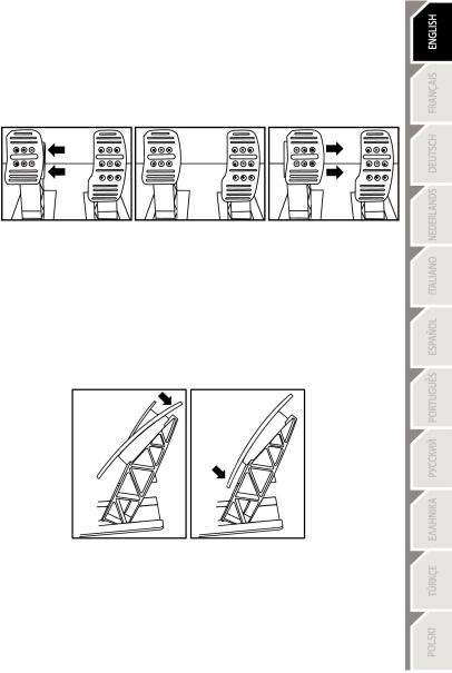
Adjusting the SPACING of the three pedals |
Downloaded |
|
- Using the included 2.5 mm Allen key (4), unscrew the two screws holding the metal fromhead (8) and |
||
its support (7) in place. |
|
www |
|
|
|
- Select your preferred position (to the left, centered, or to the right), then replace and re-tighten the. |
||
screws so that the metal head (8) and its support (7) are held firmly in place. |
vandenborre |
|
Examples illustrating the brake pedal: |
|
|
|
|
|
|
|
. |
|
|
be |
Left position |
Centered position (default) |
Right position |
|
Number of possible spacing positions per pedal: |
|
|
- Three for accelerator pedal |
|
|
- Three for brake pedal |
|
|
- Three for clutch pedal |
|
Adjusting the INCLINATION of the pedals
-Using the included 2.5 mm Allen key (4), unscrew the two screws holding the metal head (8) and its support (7) in place.
-Turn the plastic head support (7) 180°, then replace and re-tighten the screws so that the metal head (8) and its support (7) are held firmly in place.
Examples illustrating the accelerator pedal:
Less inclined position |
More inclined position (default) |
Number of possible inclination positions per pedal:
-Two for accelerator pedal
-Two for brake pedal
-Two for clutch pedal
19/24
Downloaded |
|
|
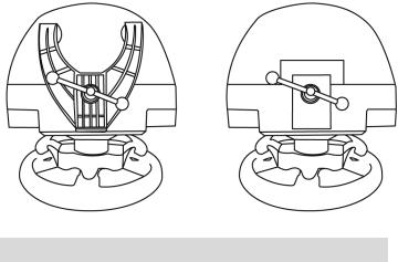
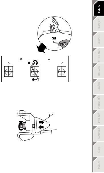
Installing the conical stop (“CONICAL RUBBER BRAKE” mod) |
|
|
This modification (or “mod”) is not essential, and is not installed by default. This meansfromthat the |
|
|
brake pedal functions perfectly even if the mod is not installed. |
www |
|
|
|
|
|
. |
|
This mod lets you experience a different feeling and resistance when braking. |
vandenborre |
|
It’s up to you whether or not to install it, depending on your own preferences. |
|
|
- Screw the conical stop (2) onto its metal support (1). |
|
. |
- Screw the position adjustment nut (5) onto the bottom (onto the conical stop’s screw thread). |
be |
|
|
|
|
- Position the unit at the back of the brake pedal’s arm.
20/24
|
Downloaded |
- Using the included 2.5 mm Allen key (4), attach the unit using the attachment screw (3) and the |
|
small central screw thread located on the underside of the pedal set. |
from |
|
|
|
www |
|
. |
|
vandenborre |
|
. |
|
be |
The “CONICAL RUBBER BRAKE” mod is now installed!
Adjusting the brake pedal’s RANGE of travel and STRENGTH of resistance
By slightly unscrewing the nut (5), you can further strengthen the resistance of the brake pedal by moving the conical stop (2) closer to the back of the pedal’s arm (if necessary, use a 14 mm wrench or pliers to re-tighten the nut and maintain the selected position). The closer the conical stop is positioned to the back of the pedal’s arm, the greater the strength of resistance will be.
Note: When the conical stop is very close to the back of the brake pedal’s arm, you may experience difficulties in reaching the maximum calibration value. Should that be the case:
*Slowly, press very hard on the brake pedal so as to reach the maximum value (if necessary, stand very briefly on the pedal – just for a second), then release the pressure; or else
*Move the conical stop a bit farther away from the back of the brake pedal’s arm.
21/24
CONSUMER WARRANTY INFORMATION |
Downloaded |
|
Worldwide, Guillemot Corporation S.A., whose registered office is located at Place du Granier, B.P. |
|
|
97143, 35571 Chantepie, France (hereinafter “Guillemot”) warrants to the consumer that this |
|
|
|
from |
|
Thrustmaster product shall be free from defects in materials and workmanship, for a warranty period |
|
|
which corresponds to the time limit to bring an action for conformity with respect to this product. In |
|
|
the countries of the European Union, this corresponds to a period of two (2) years from deliverywwwof |
|
|
the Thrustmaster product. In other countries, the warranty period corresponds to the time limit to |
|
|
|
. |
|
product (if no such action exists in the corresponding country, then the warranty period shall be onevandenborre |
||
bring an action for conformity with respect to the Thrustmaster product according to applicable laws |
|
|
of the country in which the consumer was domiciled on the date of purchase of the Thrustmaster |
|
|
(1) year from the original date of purchase of the Thrustmaster product). |
|
be |
|
|
. |
Notwithstanding the above, rechargeable batteries are covered by a warranty period of six (6) months from the date of original purchase.
Should the product appear to be defective during the warranty period, immediately contact Technical Support, who will indicate the procedure to follow. If the defect is confirmed, the product must be returned to its place of purchase (or any other location indicated by Technical Support).
Within the context of this warranty, the consumer’s defective product shall, at Technical Support’s option, be either replaced or returned to working order. If, during the warranty period, the Thrustmaster product is subject to such reconditioning, any period of at least seven (7) days during which the product is out of use shall be added to the remaining warranty period (this period runs from the date of the consumer’s request for intervention or from the date on which the product in question is made available for reconditioning, if the date on which the product is made available for reconditioning is subsequent to the date of the request for intervention). If permitted under applicable law, the full liability of Guillemot and its subsidiaries (including for consequential damages) is limited to the return to working order or the replacement of the Thrustmaster product. If permitted under applicable law, Guillemot disclaims all warranties of merchantability or fitness for a particular purpose.
This warranty shall not apply: (1) if the product has been modified, opened, altered, or has suffered damage as a result of inappropriate or abusive use, negligence, an accident, normal wear, or any other cause unrelated to a material or manufacturing defect (including, but not limited to, combining the Thrustmaster product with any unsuitable element, including in particular power supplies, rechargeable batteries, chargers, or any other elements not supplied by Guillemot for this product);
(2) if the product has been used for any use other than home use, including for professional or commercial purposes (game rooms, training, competitions, for example); (3) in the event of failure to comply with the instructions provided by Technical Support; (4) to software, said software being subject to a specific warranty; (5) to consumables (elements to be replaced over the product’s lifespan: disposable batteries, audio headset or headphone ear pads, for example); (6) to accessories (cables, cases, pouches, bags, wrist-straps, for example); (7) if the product was sold at public auction.
This warranty is nontransferable.
The consumer’s legal rights with respect to laws applicable to the sale of consumer goods in his or her country are not affected by this warranty.
22/24
Additional warranty provisions |
Downloaded |
|
|
During the warranty period, Guillemot shall not provide, in principle, any spare parts, as Technical |
|
||
Support is the only party authorized to open and/or recondition any Thrustmaster pro |
uct (with the |
|
|
exception of any reconditioning procedures which Technical Support may requestfromthat the |
|
||
consumer carry out, by way of written instructions – for example, due to the simplicity and the lack |
|
||
of confidentiality of the reconditioning process – and by providing the consumer with the requiredwww |
|
||
spare part(s), where applicable). |
|
. |
|
|
vandenborre |
||
whose warranty period has expired. |
|
||
Given its innovation cycles and in order to protect its know-how and trade secrets, Guillemot shall |
|
||
not provide, in principle, any reconditioning notification or spare parts for any Thrustmaster product |
|
||
In the United States of America and in Canada, this warranty is limited to the product’s internal |
. |
||
be |
|||
mechanism and external housing. In no event shall Guillemot or its affiliates be held liable to any third party for any consequential or incidental damages resulting from the breach of any express or implied warranties. Some States/Provinces do not allow limitation on how long an implied warranty lasts or exclusion or limitation of liability for consequential or incidental damages, so the above limitations or exclusions may not apply to you. This warranty gives you specific legal rights, and you may also have other rights which vary from State to State or Province to Province.
Liability
If permitted under applicable law, Guillemot Corporation S.A. (hereinafter “Guillemot”) and its subsidiaries disclaim all liability for any damages caused by one or more of the following: (1) the product has been modified, opened or altered; (2) failure to comply with assembly instructions; (3) inappropriate or abusive use, negligence, an accident (an impact, for example); (4) normal wear; (5) the use of the product for any use other than home use, including for professional or commercial purposes (game rooms, training, competitions, for example). If permitted under applicable law, Guillemot and its subsidiaries disclaim all liability for any damages unrelated to a material or manufacturing defect with respect to the product (including, but not limited to, any damages caused directly or indirectly by any software, or by combining the Thrustmaster product with any unsuitable element, including in particular power supplies, rechargeable batteries, chargers, or any other elements not supplied by Guillemot for this product).
TECHNICAL SUPPORT
http://support.thrustmaster.com
23/24

COPYRIGHT |
Downloaded |
|
© 2017 Guillemot Corporation S.A. All rights reserved. Thrustmaster® is a registered trademark of |
|
|
Guillemot Corporation S.A. All other trademarks are the property |
of their respective owners. |
|
|
from |
|
Illustrations not binding. Contents, designs and specifications are subject to change without notice and |
|
|
may vary from one country to another. Made in China. |
www |
|
FCC STATEMENT |
|
|
. |
|
|
1. This device complies with Part 15 of the FCC Rules. Operation is subject to the following two |
|
|
conditions: |
vandenborre |
|
(1) This device may not cause harmful interference, and |
|
|
(2) This device must accept any interference received, including interference that may cause |
. |
|
undesired operation. |
|
be |
|
|
|
2. Changes or modifications not expressly approved by the party responsible for compliance could void the user's authority to operate the equipment.
ENVIRONMENTAL PROTECTION RECOMMENDATION
*In the European Union: At the end of its working life, this product should not be disposed of with standard household waste, but rather dropped off at a collection point for the disposal of Waste Electrical and Electronic Equipment (WEEE) for recycling.
This is confirmed by the symbol found on the product, user manual or packaging. Depending on their characteristics, the materials may be recycled. Through recycling and other forms of processing Waste Electrical and Electronic Equipment, you can make a significant contribution towards helping to protect the
environment.
Please contact your local authorities for information on the collection point nearest you.
For all other countries: Please adhere to local recycling laws for electrical and electronic equipment.
Retain this information. Colours and decorations may vary.
Plastic fasteners and adhesives should be removed from the product before it is used. www.thrustmaster.com
*Applicable to EU and Turkey only
*
24/24
POUR XBOX ONE
Downloaded
from
www . Manuel de l’utilisateurvandenborre . be
ATTENTION :
Pour que le volant TX Racing Wheel fonctionne correctement avec les jeux XBOX ONE,
il peut être nécessaire d’installer les mises à jour automatiques de ces jeux
(disponibles lorsque votre console est connectée à Internet).
1/24
CARACTÉRISTIQUES TECHNIQUES
Downloaded from
www . vandenborre . be
1 |
Base du volant |
7 |
Bouton Xbox Guide |
2 |
Roue du volant |
8 |
Voyant lumineux Blanc |
3 |
2 leviers séquentiels de changement de vitesse |
9 |
Gros pas de vis (pour le système de |
4 |
(Up & Down) |
10 |
fixation et la vis de serrage) |
Croix multidirectionnelle |
Système de fixation |
||
5 |
Switch 3 positions |
11 |
Vis de serrage métallique |
6 |
Bouton MODE + Voyant lumineux Rouge/Vert |
|
|
12 |
Thrustmaster Quick Release |
15 |
Câble et connecteur USB du volant |
13 |
Appairage contrôleur (pour détection Kinect™) |
16 |
Connecteur pour la boîte de vitesses |
14 |
Connecteur type A ou B pour l’alimentation |
17 |
(vendue séparément prochainement) |
|
secteur |
Connecteur pour le pédalier |
(diffère d’un pays à l’autre)
2/24
RELIER LE VOLANT AU SECTEUR = A LIRE IMPERATIVEMENTDownloaded
En fonction du pays où vous avez acheté votre volant, l’alimentation secteur de votre volant diffère.
Elle est : |
from |
||||
|
|||||
|
|
|
|
||
Soit interne avec : |
|
www |
|||
* Boitier d’alimentation directement dans la base du volant avec connecteur type A |
. |
|
|
||
* Câble d’alimentation secteur 220-240V. |
vandenborre |
||||
= uniquement compatible avec du courant 220-240V. |
|||||
|
|
|
|||
|
|
. |
|||
|
|
|
|
be |
|
|
Ne jamais brancher le câble 220-240V |
|
|||
|
|
|
|
||
|
sur une prise de courant 100-130V !!! |
|
|
|
|
|
Ne jamais relier ce câble à un adaptateur secteur !!! |
|
|
||
Soit interne avec :
*Boitier d’alimentation directement dans la base du volant avec connecteur type A
*Câble d’alimentation secteur 100-125V.
=uniquement compatible avec du courant 100-125V.
 Ne jamais brancher le câble 100-125V sur une prise de courant 220-240V !!!
Ne jamais relier ce câble à un adaptateur secteur !!!
IMPORTANT : Si vous ne connaissez pas le voltage de la zone dans laquelle vous utilisez le volant, reportez-vous- au fournisseur local d’électricité.
Soit externe avec :
*Boitier d’alimentation externe à la base du volant avec connecteur type B
*Câble d’alimentation secteur
=compatible avec tout type de courant 110-240V.
3/24

AVERTISSEMENTS |
Downloaded |
|
|
|
|
Avant d’utiliser ce produit, lisez attentivement cette documentation et conservez-la pour pouvoir la |
||
consulter ultérieurement. |
from |
|
Avertissement – Choc électrique |
|
www |
|
. |
|
* Conservez le produit dans un endroit sec et ne l’exposez ni à la poussière ni au soleil. |
vandenborre |
|
* Respectez les sens de branchement. |
|
|
* Ne tordez pas et ne tirez pas sur les connecteurs et câbles. |
|
|
* Ne renversez pas de liquide sur le produit et ses connecteurs. |
|
. |
* Ne mettez pas le produit en court-circuit. |
|
be |
* Ne démontez jamais le produit, ne le jetez pas au feu et ne l’exposez pas à des températures élevées. * N’utilisez pas de câble d’alimentation autre que celui fourni avec votre volant
* N’utilisez pas le câble d’alimentation secteur si celui-ci où ses connecteurs sont endommagés, fendus ou cassés.
* Assurez-vous que le câble d’alimentation secteur est parfaitement inséré dans la prise murale et dans son connecteur situé à l’arrière de la base du volant.
* N’ouvrez pas l’appareil. L’appareil ne contient pas de pièces réparables par l'utilisateur. Confiez toute réparation au fabricant, à une agence spécifiée ou un technicien qualifié.
* Utilisez uniquement les systèmes de fixation /accessoires spécifiés par le fabricant.
* Si le volant fonctionne de manière anormale (s’il émet des sons, de la chaleur ou des odeurs anormales), arrêtez immédiatement de l’utiliser, débranchez le câble d’alimentation de la prise électrique et déconnectez les autres câbles.
* Lorsque vous n’utilisez pas le volant pendant une période prolongée, débranchez le câble d’alimentation secteur de la prise électrique.
 Grilles d’aération
Veuillez à n’obstruer aucune grille d’aération de la base du volant. Pour assurer une ventilation optimale, respectez les points ci-après :
*Placez la base à 10 cm au moins d’une surface murale.
*Ne placez pas la base dans un endroit exigu.
*Ne couvrez pas la base.
*Ne laissez pas la poussière s’accumuler sur les grilles d’aération.
Pour des raisons de sécurité, ne jouez pas pieds nus ou en chaussettes lorsque vous utilisez le pédalier.
THRUSTMASTER® DECLINE TOUTE RESPONSABILITE EN CAS DE
BLESSURE SUITE A UNE UTILISATION DU PEDALIER SANS CHAUSSURES.
 Avertissement – Blessures dues au retour de force et aux mouvements répétitifs
Jouer avec un volant à retour de force peut causer des douleurs aux muscles et aux articulations. Afin d’éviter tout problème :
*Evitez les périodes trop longues de jeu.
*Faites une pause de 10 à 15 minutes après chaque heure de jeu.
*Si vous éprouvez fatigue ou douleur au niveau des mains, des poignets, des bras, des pieds ou des
jambes, cessez de jouer et reposez-vous pendant quelques heures avant de recommencer à jouer.
4/24
 Avertissement – Blessures dues au retour de force et aux mouvementsDownloadedrépétitifs (suite)
*Si les symptômes ou les douleurs indiqués ci-dessus persistent lorsque vous reprenezfromle jeu, arrêtez de jouer et consultez votre médecin. www
*Laissez hors de portée des enfants. .
*Lors des phases de jeu, laissez toujours vos deux mains correctement positionnées sur le volvandenborrent sans jamais le lâcher complètement.
*Lors des phases de jeu, ne placez jamais vos mains ou vos doigts sous les pédales ou à proximité du pédalier. .
*Lors des phases de calibration et de jeu, ne jamais introduire une main ou un bras à l’intérieur de la be roue du volant.
*Vérifiez que la base du volant est correctement fixée, conformément aux instructions du manuel.
PRODUIT LOURD
Produit à manipuler uniquement par des personnes âgées de 16 ans ou plus
TOUJOURS
Ne pas laisser tomber le produit sur vous ou une autre personne
JAMAIS |
JAMAIS |
5/24
 Loading...