


Telefunken TSOP1856ST1, TSOP1840ST1, TSOP1833ST1, TSOP1838ST1, TSOP1836ST1 Datasheet
...
TSOP18..ST1
Vishay Telefunken
Photo Modules for PCM Remote Control Systems
Available types for different carrier frequencies
Type |
fo |
Type |
fo |
TSOP1830ST1 |
30 kHz |
TSOP1833ST1 |
33 kHz |
TSOP1836ST1 |
36 kHz |
TSOP1837ST1 |
36.7 kHz |
|
|
|
|
TSOP1838ST1 |
38 kHz |
TSOP1840ST1 |
40 kHz |
|
|
|
|
TSOP1856ST1 |
56 kHz |
|
|
Description
The TSOP18..ST1 ± series are miniaturized receivers for infrared remote control systems. PIN diode and preamplifier are assembled on lead frame, the epoxy package is designed as IR filter.
The demodulated output signal can directly be decoded by a microprocessor. The main benefit is the reliable function even in disturbed ambient and the protection against uncontrolled output pulses.
16123
Features
DPhoto detector and preamplifier in one package
DInternal filter for PCM frequency
DTTL and CMOS compatibility
DOutput active low
DImproved shielding against electrical field disturbance
DSuitable burst length ≥ 6 cycles/burst
Special Features
DSmall size package
DEnhanced immunity against all kinds of disturbance light
DNo occurrence of disturbance pulses at the output
DShort settling time after power on (<200ms)
Block Diagram
|
|
|
3 |
Input |
|
Control |
VS |
|
|
Circuit |
30 kW |
|
|
|
|
|
|
|
1 |
PIN |
|
|
OUT |
|
|
|
|
|
AGC |
Band |
Demodu- |
|
Pass |
lator |
|
|
|
||
|
|
|
2 |
|
|
|
GND |
9612226 |
|
|
|
Document Number 82106 |
|
|
www.vishay.de •FaxBack +1-408-970-5600 |
Rev. 1, 08-Mar-00 |
|
|
1 (6) |
TSOP18..ST1
Vishay Telefunken
Absolute Maximum Ratings
Tamb = 25_C
Parameter |
Test Conditions |
Symbol |
Value |
Unit |
Supply Voltage |
(Pin 3) |
VS |
±0.3...6.0 |
V |
Supply Current |
(Pin 3) |
IS |
5 |
mA |
Output Voltage |
(Pin 1) |
VO |
±0.3...6.0 |
V |
Output Current |
(Pin 1) |
IO |
5 |
mA |
Junction Temperature |
|
Tj |
100 |
°C |
Storage Temperature Range |
|
Tstg |
±25...+85 |
°C |
Operating Temperature Range |
|
Tamb |
±25...+85 |
°C |
Power Consumption |
(Tamb x 85 °C) |
Ptot |
50 |
mW |
Soldering Temperature |
t x 10 s, 1 mm from case |
Tsd |
260 |
°C |
Basic Characteristics
Tamb = 25_C
Parameter |
|
|
Test Conditions |
|
|
Symbol |
Min |
Typ |
Max |
Unit |
||||
Supply Current (Pin 3) |
VS = 5 V, Ev = 0 |
|
|
|
|
|
|
ISD |
0.9 |
1.2 |
1.5 |
mA |
||
|
VS = 5 V, Ev = 40 klx, sunlight |
|
|
ISH |
|
1.3 |
|
mA |
||||||
Supply Voltage (Pin 3) |
|
|
|
|
|
|
|
|
|
VS |
4.5 |
|
5.5 |
V |
Transmission Distance |
Ev = 0, test signal see fig.6, IR diode |
d |
|
35 |
|
m |
||||||||
|
TSAL6200, IF = 300 mA |
|
|
|
|
|
|
|
|
|||||
Output Voltage Low (Pin 1) |
I |
OSL |
= 0.5 mA,E |
e |
= 0.7 mW/m2, f = f |
o |
V |
|
|
250 |
mV |
|||
|
|
|
|
|
|
|
OSL |
|
|
|
|
|||
Irradiance (30 ± 40 kHz) |
Pulse width tolerance: t |
pi |
± 4/f |
< t |
< |
E |
|
0.3 |
0.5 |
mW/m2 |
||||
|
|
|
|
|
|
o |
po |
|
e min |
|
|
|
|
|
|
tpi + 6/fo, test signal see fig.6 |
|
|
|
|
|
|
|
||||||
Irradiance (56 kHz) |
Pulse width tolerance: t |
pi |
± 4/f |
< t |
< |
E |
|
0.4 |
0.7 |
mW/m2 |
||||
|
|
|
|
|
|
o |
po |
|
e min |
|
|
|
|
|
|
tpi + 6/fo, test signal see fig.6 |
|
|
|
|
|
|
|
||||||
Irradiance |
|
|
|
|
|
|
|
|
|
E |
30 |
|
|
W/m2 |
|
|
|
|
|
|
|
|
|
|
e max |
|
|
|
|
Directivity |
Angle of half transmission distance |
|
ϕ1/2 |
|
±45 |
|
deg |
|||||||
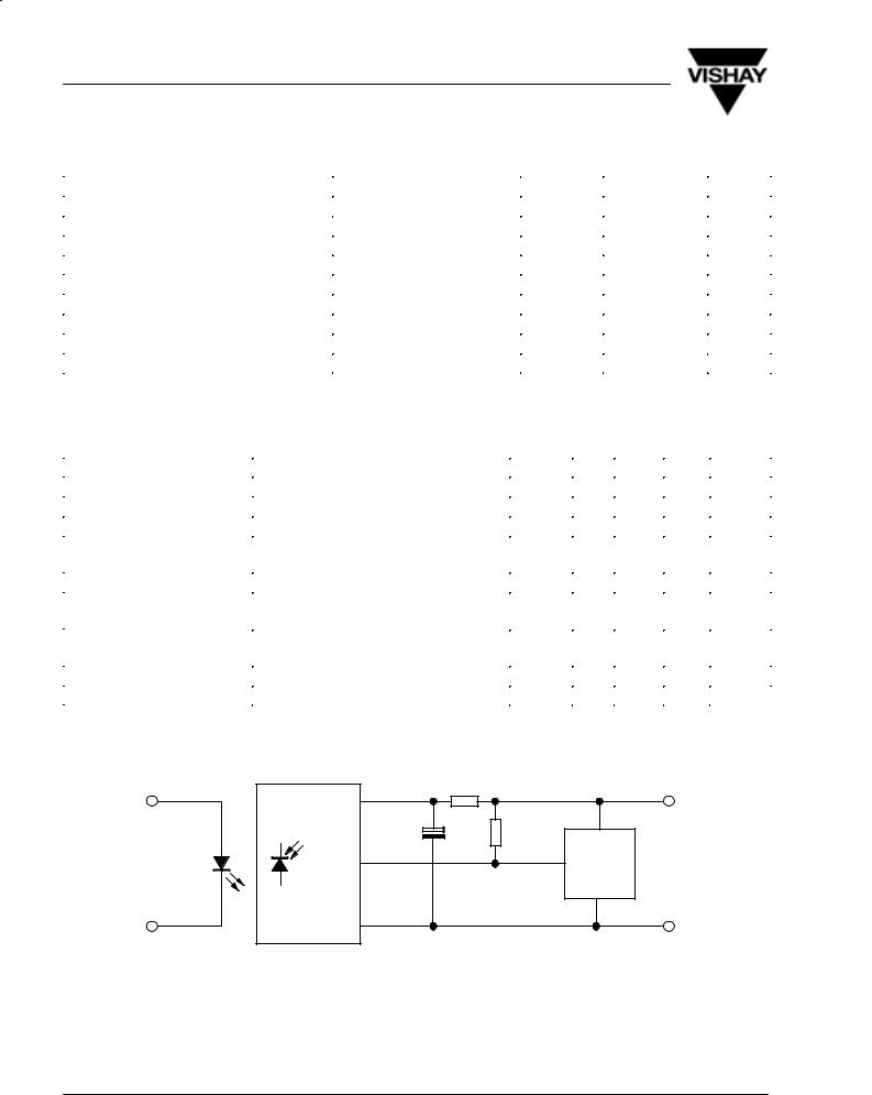
Application Circuit
100 W *) +5V **)
|
3 |
4.7 mF *) |
|
TSOP18..ST1 |
|
||
|
>10 kW |
||
TSAL62.. |
|
optional |
|
1 |
mC |
||
|
|||
|
|
||
|
2 |
|
GND
16179 |
*) recommended to suppress power supply disturbances |
|
www.vishay.de •FaxBack +1-408-970-5600 |
Document Number 82106 |
2 (6) |
Rev. 1, 08-Mar-00 |
 Loading...