


TSTS7303
TSTS730.
Vishay Telefunken
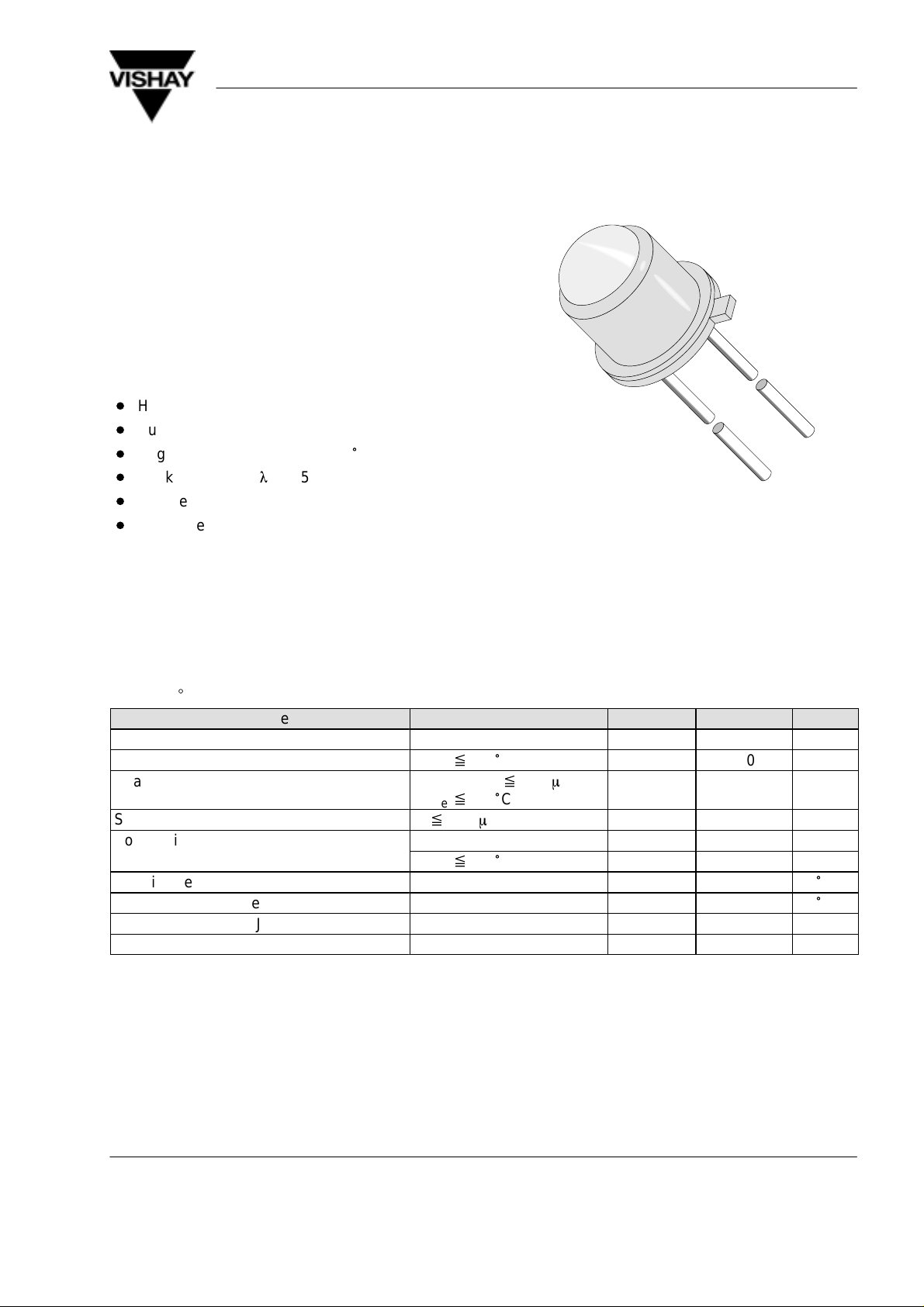
GaAs IR Emitting Diodes in Hermetically Sealed TO18
Case
Description
The TSTS730. series are infrared emitting diodes in
standard GaAs technology in a hermetically sealed
TO–18 package. Their glass lenses provide a high radiant intensity without external optics.
Features
D
High radiant intensity
D
Suitable for pulse operation
D
Angle of half intensity ϕ = ± 12
D
Peak wavelength
D
High reliability
D
Good spectral matching to Si photodetectors
lp = 950 nm
°
94 8642
Applications
Radiation source in near infrared range
Absolute Maximum Ratings
T
= 25_C
amb
Parameter Test Conditions Symbol Value Unit
Reverse Voltage V
Forward Current
Peak Forward Current
Surge Forward Current
Power Dissipation P
Junction Temperature T
Storage Temperature Range T
Thermal Resistance Junction/Ambient R
Thermal Resistance Junction/Case R
T
x 25 °C
case
tp/T = 0.5, tp x 100 ms,
T
x 25 °C
case
tp x 100 ms
T
x 25 °C
case
I
I
FM
I
FSM
P
thJA
thJC
F
stg
R
V
V
j
5 V
250 mA
500 mA
2.5 A
170 mW
500 mW
100
–55...+100
450 K/W
150 K/W
°
C
°
C
Document Number 81048
Rev. 2, 20-May-99
www.vishay.de • FaxBack +1-408-970-5600
1 (5)
TSTS730.
y
F
Vishay Telefunken
Basic Characteristics
T
= 25_C
amb
Parameter Test Conditions Symbol Min Typ Max Unit
Forward Voltage
IF = 100 mA, tp x 20 ms
Breakdown Voltage IR = 100 mA V
Junction Capacitance VR = 0 V, f = 1 MHz, E = 0 C
Radiant Power
Temp. Coefficient of
f
e
IF = 100 mA, tp x 20 ms
IF = 100 mA TK
Angle of Half Intensity ϕ ±12 deg
Peak Wavelength IF = 100 mA
Spectral Bandwidth IF = 100 mA
Rise Time IF = 1.5 A, tp/T = 0.01,
tp x 10 ms
Fall Time IF = 1.5 A, tp/T = 0.01,
tp x 10 ms
V
F
(BR)
f
e
f
l
p
Dl
t
r
t
f
1.3 1.7 V
5 V
j
30 pF
7 mW
e
–0.8 %/K
950 nm
50 nm
400 ns
400 ns
Type Dedicated Characteristics
T
= 25_C
amb
Parameter Test Conditions Type Symbol Min Typ Max Unit
Radiant Intensity IF=100mA, tp=20ms TSTS7300 I
TSTS7301 I
TSTS7302 I
TSTS7303 I
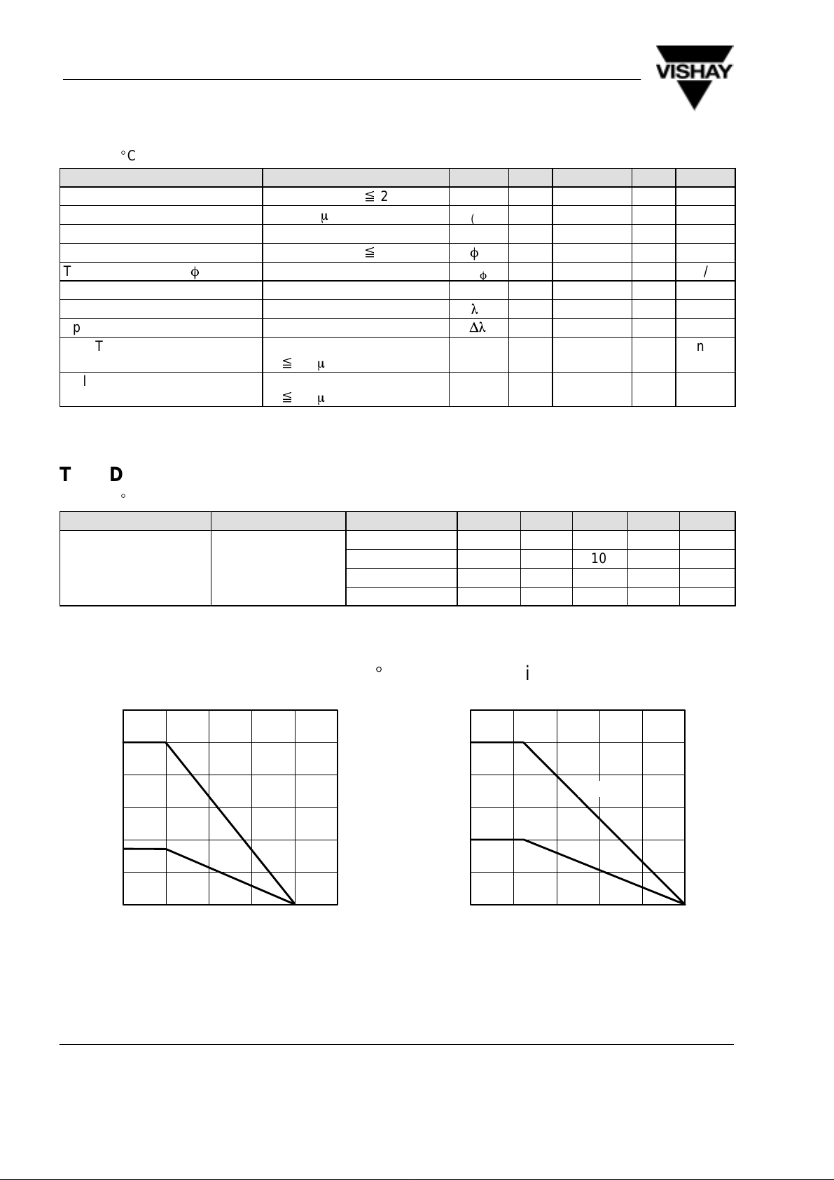
Typical Characteristics (T
600
R
thJC
500
400
300
200
R
V
P – Power Dissipation ( mW )
thJA
100
= 25_C unless otherwise specified)
amb
300
250
200
150
100
F
I – Forward Current ( mA )
50
e
e
e
e
R
thJA
4 6.3 mW/sr
6.3 10 12.5 mW/sr
10 16 20 mW/sr
16 25 32 mW/sr
R
thJC
0
0 25 50 75 100
T
94 8017 e
Figure 1. Power Dissipation vs. Ambient Temperature
www.vishay.de • FaxBack +1-408-970-5600
2 (5) Rev. 2, 20-May-99
– Ambient Temperature ( °C )
amb
125
0
020406080
T
94 8018 e
Figure 2. Forward Current vs. Ambient Temperature
– Ambient Temperature ( °C )
amb
Document Number 81048
100
 Loading...