

Page 1

- Data Brochure
Snow Detector & Melting Control 664
D 664
07/09
The Snow Detector and Melting Control 664 is designed to control up to two zones in a snow melting system. The control automatically
adjusts the mixed supply water to the snow melting system by controlling up to two boilers and a single mixing device. For mixing, the
664 can use a variable speed injection pump, a fl oating action mixing valve or a 4-20 mA device. The snow melting system may be
started manually or automatically through the use of a Snow / Ice Sensor 090. The 664 control includes a large Liquid Crystal Display
(LCD) in order to view system status and operating information.
Additional features include:
• Temporary Idle
• Optional priority zoning operation
• Slab protection for the snow melting system
• Boiler protection
• Manual Override
• Cold Weather Cut Out (CWCO)
• Remote display and adjustment capabilities
• Test sequence to ensure proper component operation
• Pump and valve exercising
• CSA C US Certifi ed (approved to applicable UL standards)
• Adjustable Warm Weather Shut Down (WWSD)
Output
4-20 mA
device
Output
Variable
Speed
driven
Output
Mixing
Valve &
Actuating
Snow/Ice Sensor
090 installed with
Sensor Socket
OR
pump
OR
Motor
Input
091 Optional
or
Slab
Sensor
Optional
Input
Slab
Sensor
Optional
%
Start Stop
Menu
Item
Snow Detector & Melting Control 664
Two Zone, Two Stage Boiler, Mixing
1 kΩ max
1+2–3
4-20 mA
Opn/
Var
4
5
Pwr
Cls6Red7Blk/
Mix
Com
8
Blu9Yel10Brn/
Do not apply power
11
Slab
Slab1
2
OR
Remote Display Module (RDM)
Remote Start / Stop Module
Input
or
Melt Demand
Idle Demand
WWSD
Minimum
Maximum
Water
Melting
12
Com13tN214Mix
15
16
Mix
Com17Boil18Out19Melt/Idle
Ret
Sup
Input
Universal
Sensor
Included
Idle Demand
Melt Demand
Made in Canada by
tekmar Control Systems Ltd.
tektra 900-01
Power 115 V
Relays 230 V (ac) 5 A 1/6 hp
Stage/Zn/P1 Relays 230 V (ac) 5 A 1/3 hp
Var. Pump 230 V (ac) 2.4 A max (FLA)
5 A max (LRA), fuse T2.5 A 250V
Demand 20 to 260 V (ac) 2 VA
Signal wiring must be rated at least 300 V.
20 21122 23224 25
Stage Stage
Demand
Input
Universal
Sensor
Included
Input
Universal
Sensor
Included
Zn
1
± 10%
50/60 Hz 600 VA
26
27
Com
Zn
Zn
2
Input
Outdoor
Sensor
Included
Tes t
28
Sys
P1
off
not testing
red
testing
red
testing paused
For maximum heat,
press and hold Test
button for 3 seconds.
Meets Class B:
Canadian ICES
FCC Part 15
30
29
Power
L
N
Input
Melt/Idle
Demand
H1198D
Input
115 V (ac)
Power
Supply
Output
System
Pump
Output
Zone
Pumps
OR
M
OR
Zone Valves
Output
Boiler
Output
Boiler
© 2009 D 664 - 07/09
1 of 36
Page 2

How To Use The Data Brochure
This brochure is organized into four main sections. They are: 1) Sequence of Operation, 2) Installation, 3) Control Settings, and 4)
Troubleshooting. The Sequence of Operation section has 6 sub-sections. We recommend reading Section A: General of the Sequence
of Operation, as this contains important information on the overall operation of the control. Then read to the sub-sections that apply to
your installation.
The Control Settings section (starting at DIP Switch Settings) of this brochure describes the various items that are adjusted and
displayed by the control. The control functions of each adjustable item are described in the Sequence of Operation.
Table of Contents
User Interface ..................................................Pg 2
Description of Display Elements ..................Pg 3
Sequence of Operation ..................................Pg 4
Section A: General Operation ..............Pg 4
Section B: Snow Melting .......................Pg 6
Section C: Boiler Operation .................Pg 8
Section D: Melting Enable / Disable ....Pg 9
Section E: Melting Operation ............... Pg 12
Section F: Idling Operation ...................Pg 14
Installa tion ....................................................... Pg 15
Electrical Connections .......................... Pg 15
Testing The Wiring .................................Pg 18
DIP Switch Settings ........................................Pg 20
Access Levels .................................................Pg 21
Control Settings ..............................................Pg 22
View Menu ..............................................Pg 22
Adjust Menu ...........................................Pg 23
Monitor Menu .........................................Pg 26
Schedule Menu ......................................Pg 28
Miscellaneous Menu .............................Pg 28
Testing and Troubleshooting ........................Pg 29
Error Messages ...................................... Pg 31
Technical Data .................................................Pg 36
Limited Warranty ............................................Pg 36
User Interface
The 664 uses a Liquid Crystal Display (LCD) as the method of supplying information. You use the LCD in order to setup and monitor
the operation of your system. The 664 has four push buttons (Menu, Item,
your control, record your settings in the ADJUST Menu table which is found in the second half of this brochure.
▲, ▼) for selecting and adjusting settings. As you program
Menu
All of the items displayed by the control are organized into various menus. These menus
are listed on the left hand side of the display (Menu Field). To select a menu, use the
Menu button. By pressing and releasing the Menu button, the display will advance to
the next available menu. Once a menu is selected, there will be a group of items that
can be viewed within the menu.
Item
The abbreviated name of the selected item will be displayed in the item field of the
display. To view the next available item, press and release the Item button. Once you
have reached the last available item in a menu, pressing and releasing the Item button
will return the display to the first item in the selected menu.
Adjust
To make an adjustment to a setting in the control, begin by selecting the appropriate
menu using the Menu button. Then select the desired item using the Item button. Finally,
use the
Additional information can be gained by observing the Status fi eld of the LCD. The status
fi eld will indicate which of the control’s outputs are currently active. Most symbols in the
status fi eld are only visible when the VIEW Menu is selected.
© 2009 D 664 - 07/09
2 of 36
▲ and / or ▼ button to make the adjustment.
Menu Item
Menu Item
Menu Item
Page 3
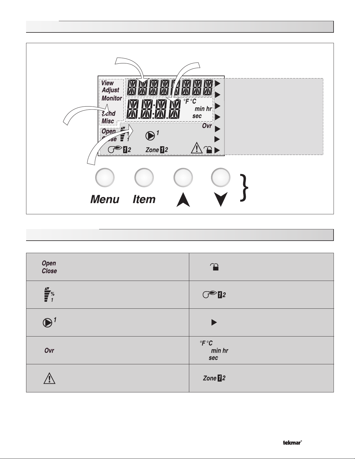
Display
Item Field
Displays an abbreviated
name of the selected item
Menu Field
Displays the
current menu
Status Field
Displays the
current status
of the control's
inputs, outputs
and operation
Number Field
Displays the current value of the selected item
Melt Demand
Idle Demand
WWSD
Minimum
Maximum
Water
Melting
Buttons
Selects Menus, Items
and adjust settings
Symbol Description
Open / Close
Displays when the actuator is opening or
closing the mixing valve.
Mixing Device Output Scale
Shows output of injection pump, mixing valve
or 4-20 mA device. Arrows show whether the
output is increasing or decreasing.
Pump
Displays when the system pump is operating.
Override
Displays when the control is in override mode.
Warning
Displays when an error exists or when a limit
has been reached.
Lock / Unlock
Displays when the access levels are
locked or unlocked.
Burner
Displays when the Stage 1 and / or
Stage 2 relay is turned on.
Pointer
Displays the control operation as
indicated by the text.
°F, °C, min, hr, sec
Units of measurement.
Zone
Displays when a zone is in operation.
© 2009 D 664 - 07/09
3 of 36
Page 4
Definitions
The following defined terms and symbols are used throughout this manual to bring attention to the presence of hazards of various risk
levels, or to important information concerning the life of the product.
- Warning Symbol: Indicates presence of hazards which can cause severe personal injury, death or
substantial property damage if ignored.
INSTALLATION
CATEGORY II
- Double insulated
- Local level, appliances
Sequence of Operation
Section A
General
Operation
Page 4 - 5
Section F
Idling
Operation
Page 14
Section B
Snow
Melting
Page 5 - 7
Section C
Boiler
Operation
Page 7 - 9
Section D
Melting Enable
/ Disable
Page 9 - 11
Section E
Melting
Operation
Page 12 - 13
Section A: General Operation
POWERING UP THE CONTROL
When the Snow Detector and Melting Control 664 is powered up, the control displays all LCD segments for 2 seconds, then the
control type number in the LCD for 2 seconds. Next, the software version is displayed for 2 seconds. Finally, the control enters into
the normal Operating mode and the LCD defaults to displaying the current outdoor air temperature.
MIXING DEVICE SELECTION (MIXING)
The 664 can supply a lower fluid temperature to the snow melting system by using a variable speed injection pump, a floating action
mixing valve or a modulating 4-20 mA device. The selection is made under the Mixing item in the ADJUST menu.
Variable Speed Injection (VAR)
A standard wet rotor circulator is connected to the 664 on the Pwr Mix
and Opn / Var terminals (4 and 3). The 664 increases or decreases the
power output to the circulator based on the system requirements. For
correct sizing and piping of the variable speed injection pump, refer to
Essay E 021. A visual indication of the current variable speed output is
displayed in the LCD in the form of a segmented bar graph.
Floating Action (FLOT)
A floating action motor is connected to the 664 on the Pwr Mix,
Opn / Var and Cls terminals (4, 3 and 5). The 664 pulses the actuator
motor open or close based on the system requirements. The mixing
valve that the actuator is connected to can be either a 2-way, 3-way or
4-way valve. A visual indication of the current position of the valve is
displayed in the LCD in the form of a segmented bar graph.
4-20 mA Output (4-20)
A 4-20 mA device is connected to the 664 on the 4-20 mA + and 4-20 mA – terminals (1 and 2). The 664 increases or decreases
the modulating output to the 4-20 mA device based on the system requirements. The 4-20 mA output can be used to operate a
variety of actuating motors for mixing valves and motor drives for larger pumps. A visual indication of the current output of the
4-20 mA device is displayed in the LCD in the form of a segmented bar graph.
© 2009 D 664 - 07/09
4 of 36
Page 5
MIXING TARGET (MIX TRG)
The mixing target temperature is the supply fluid temperature calculated by the control. The control will operate the snow melt
system so that the mix supply temperature reaches the mixing target except while providing boiler return protection for the boiler.
MIXING MAXIMUM (MIX MAX)
The Mix Max sets the highest fluid temperature that the control is allowed to calculate as the mixing target temperature. If the control
does target the Mix Max setting, and the mix supply temperature is near the MIX MAX, the Maximum pointer is displayed in the LCD
while the MIX SUP temperature is being viewed.
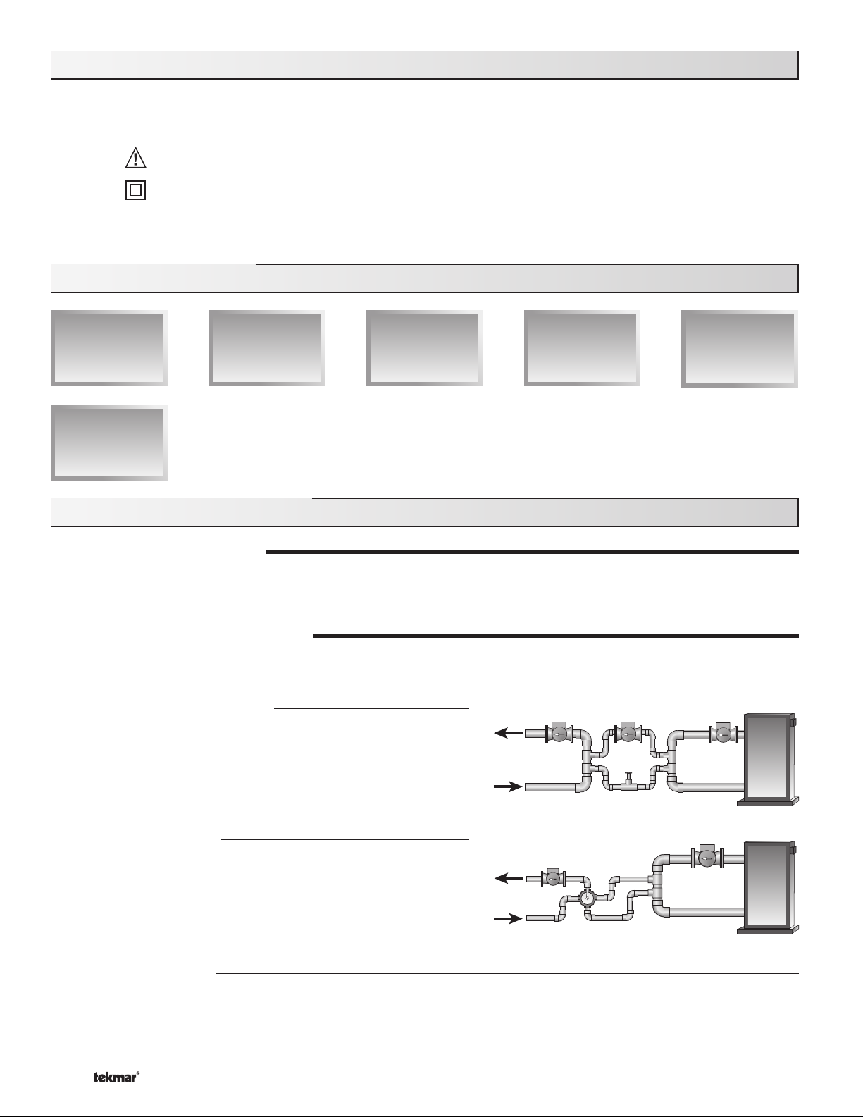
BOILER PROTECTION (Boil MIN)
The 664 is capable of providing boiler protection from cold mixing system
Mixing
Sensor
Boiler Supply
Sensor
return fl uid temperatures. If the boiler sensor temperature is cooler than
the Boil Min setting while the boiler(s) is fi ring, the 664 reduces the output
from the mixing device. This limits the amount of cool return water to the
OR
boiler(s) and allows the boiler temperature to recover. This feature can
only be used if the Boil Sens item is set to Sup or Ret. The 664 can not
provide boiler protection if the Boil Sens item is set to None.
Boiler Return
Sensor
EXERCISING (EXERCISE)
The 664 has a built in pump and valve exercising function. The exercising period is adjustable and is factory set at 70 hours. If a
pump or valve output has not been operated at least once during every exercising period, the control turns on the output for 10
seconds. This minimizes the possibility of a pump or valve seizing during a long period of inactivity. In the case where a mixing valve is
being used as the mixing device, the 664 ensures that the valve operates over its entire range at least once each exercising period.
Note: The exercising function does not work if power to the control, valves or pumps is disconnected.
Section B: Snow Melting
Section B1
General
Snow Melting
Section B1: General Snow Melting
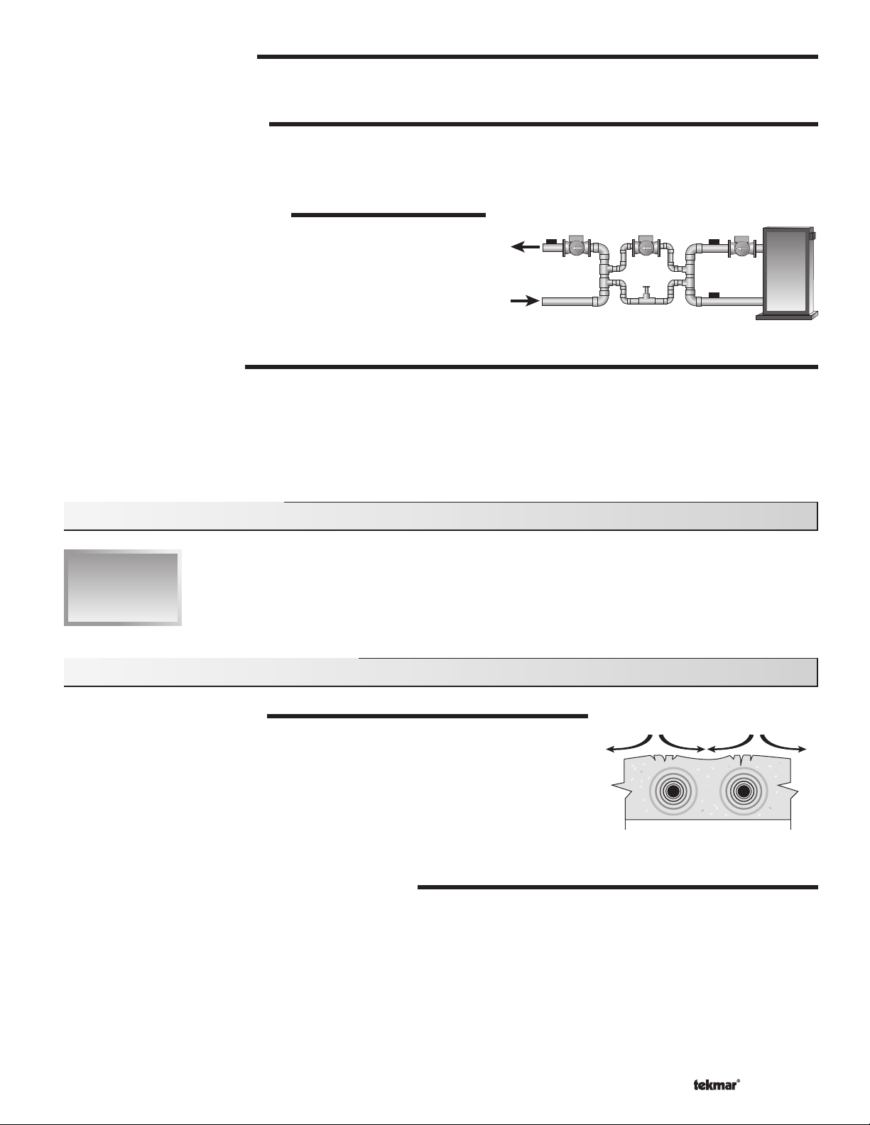
SLAB PROTECTION (∆T MAX)
The control can limit the rate at which heat is applied to the currently operating zone through
the ∆T Max setting. The ∆T (delta T) is the temperature difference between the snow melting
supply temperature and the snow melting return temperature. By limiting this temperature
difference, the rate at which heat is applied to the currently operating zone can be controlled
and thermal stresses in the slab can be minimized. When the control is operating at the
∆T MAX, the Maximum pointer can be seen when viewing the ∆T item in the VIEW menu.
The control provides slab protection differently based on boiler sensor placement.
Note: The ∆T MAX function is only available if the PRIORITY item is set to COND or FULL.
VISCOSITY COMPENSATION (EXCEEDING ∆T MAX)
At low temperatures, the glycol solutions used in snow melting systems become very viscous and difficult to pump. In order to
overcome this condition during a cold start of a snow melting system, the 664 is allowed to exceed the ∆T Max setting for a period of
time in order to warm the glycol solution. This allows the control to compensate for the high viscosity of the glycol solution and is used
when the mixing return temperature is below 30°F (-1°C). When the control exceeds the ∆T Max setting, the Maximum pointer will
fl ash when viewing the ∆T item in the VIEW menu.
Note: This operation only occurs if the PRIORITY item is set to COND or FULL.
© 2009 D 664 - 07/09
5 of 36
tensile stresses
Page 6
SOFT START
When the control starts applying heat to the slab, the supply temperature to the snow melting system is ramped up over a period of
time until it reaches the target mixed supply temperature. This feature helps reduce thermal stresses in the slab.
Note: This operation only occurs if the Boil SENS item is set to RET or NONE.
RUNNING TIME (RUN TIME)
The running time is the length of time that a zone operates once it has reached its slab target temperature. During the time that a
zone is approaching its slab target temperature, the Run Time does not decrease. Once a zone reaches its slab target temperature
the Run Time begins counting down. When the Run Time reaches 0:00 as displayed in the Status item of the appropriate zone in the
VIEW menu, the zone has fi nished melting.
Note: The running time is only applicable when a manual melting enable signal starts the snow melting system. Refer to Section D1
for a description of a manual melting enable.
WARM WEATHER SHUT DOWN (WWSD)
The control has a warm weather shut down for each zone that prevents the control from entering the Melt or Idle modes in order to
conserve energy. While a zone is in WWSD, the word WWSD is displayed in the STATUS 1 or STATUS 2 items in the VIEW menu.
When both zones enter WWSD, the 664 turns on the WWSD pointer in the display.
Automatic (Auto)
There is a warm weather shut down for each zone. When both the slab temperature of a
zone and the outdoor temperature exceed the zone’s Melt Tem perature setting by more
than 2°F (1°C), the zone enters into WWSD. While a zone is in WWSD, the word WWSD
Outdoor
Temperature
WWSD
Slab
Temperature
MELT
is displayed in the STATUS item of the appropriate zone in the VIEW menu. When both
zones enter WWSD, the 664 turns on the WWSD pointer in the display.
Control enters
Adjustable WWSD
Idle and waits
for Melt Enable
IDLE
When the WWSD is set to a temperature, the WWSD occurs when the outdoor air
temperature exceeds the WWSD setting by 1°F (0.5°C) and when the slab temperature of
a zone exceeds 34°F (1°C). The zone exits WWSD when the outdoor air temperature falls
1°F (0.5°C) below the WWSD setting or if the slab temperature of the zone falls below 34°F
CWCO
(1°C). This allows the Melting Temperature setting to be set higher than the WWSD. This is
useful where high slab temperatures are required to melt the snow or ice. A good example
of this is installations using paving bricks on top of sand and concrete layers.
COLD WEATHER CUT OUT (CWCO)
Maintaining the zone(s) at either the melting or idling temperature during extremely cold temperatures can be expensive or
impossible. The control turns the snow melting system off when the outdoor air temperature drops below the Cold Weather Cut
Out (CWCO) temperature. While the control is in CWCO, the word CWCO is displayed in the STATUS 1 and STATUS 2 item in the
VIEW menu. If a Snow / Ice Sensor 090 is used, the heater in the sensor is kept on during CWCO until the control detects moisture.
If water is detected, the heater is turned off but the control retains the moisture detected information. When the outdoor temperature
rises above the CWCO temperature, the control exits CWCO and if the Snow / Ice Sensor 090 detected moisture during CWCO, the
control initiates Melting mode. If the control has been started prior to the CWCO, it resumes the Melting mode once the outdoor air
temperature rises above the CWCO temperature.
STATUS 1 and 2 (STATUS)
While in the VIEW menu there are a number of items available to determine the current status of zone 1 and zone 2. To view the
current status of zone 1, select the STATUS 1 item in the VIEW menu. To view the current status of zone 2, select the STATUS 2 item
in the VIEW menu.
• STRT The word STRT is displayed after the snow melting system has been manually enabled. It is displayed until the
zone reaches its slab target temperature. If the zone is at its slab target temperature, STRT is displayed for five
seconds after the snow melting system has started operation. This is to verify that the control has entered into
the Melting mode.
• STOP The word STOP is displayed for fi ve seconds after the snow melting system has been manually disabled. The
word STOP is also displayed if either a Remote Start / Stop Module 039, Remote Display Module 040 or the Stop
on the control stops the snow melting system and an external melt demand is still present.
• IDLE The word IDLE is displayed as long as the zone is operating at its idling temperature.
• “IDLE” The word IDLE is fl ashed on the display as long as the zone is operating in temporary idle.
• EXT The word EXT is displayed when the RUN TIME has reached 0:00 and the control still has an external melt demand.
In this situation, the zone continues melting until the melt demand is removed or the control is stopped.
© 2009 D 664 - 07/09
6 of 36
Page 7
• DET The word DET is displayed after the snow melting system has been automatically enabled by the Snow / Ice
Sensor 090 and the zone is at its slab target temperature. DET is also displayed once the control is manually
enabled after automatic detection by the 090 and the running time has counted down to 0:00.
• 0:00 to 23:59 hr While the zone is up to temperature and melting, the remaining RUN TIME is displayed.
• INF If an infi nite RUN TIME is selected and the zone is melting, INF is displayed.
• WWSD When the zone is in Warm Weather Shut Down, WWSD is displayed.
• CWCO When the control is in Cold Weather Cut Out, CWCO is displayed.
BOILER PROTECTION
Refer to Section A for a description of boiler protection.
BOILER OPERATION
Refer to Section C for a description of boiler operation.
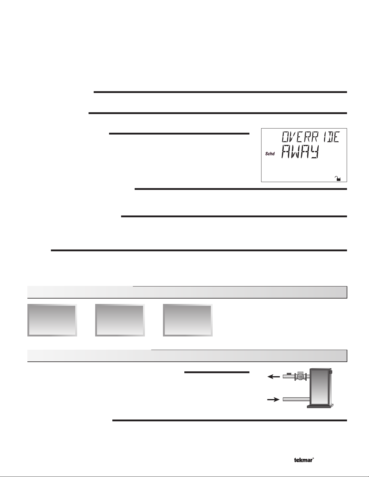
SNOW MELTING OVERRIDE
If the Away setting is selected in the SCHEDULE menu, the snow melting system is shut
down. Both the Melting and Idling temperatures are ignored as long as the control remains
in the Away mode.
SYSTEM PUMP OPERATION (Sys P1)
The System Pump (Sys P1) contact closes and remains closed as long as at least one of the zones is either in the Melting or Idling mode.
The System Pump contact shuts off if the control is in CWCO, if both zones are in WWSD, or if there is no call for Melting or Idling.
ZONE OUTPUTS (Zn 1 and Zn 2)
The Zone 1 (Zn 1) contact and the Zone 2 (Zn 2) contact operate based on the Melting and / or Idling operation. Refer to Melting
Section E and / or Idling Section F for a description of how the zone contact(s) operate. The Zone Pump contact(s) shuts off if the
control is in CWCO, if the corresponding zone(s) is in WWSD, or if there is no call for Melting or Idling.
PURGE
The system pump (Sys P1) and zoning device(s) (Zn 1 and Zn 2) continue to operate for up to 2 minutes after the last demand is
removed. This purges the residual heat from the boiler(s) into the snow melting slab. If the boiler temperature drops below the Boil Min
setting after 20 seconds, the purge is aborted and the system pump and zoning device(s) are turned off.
Section C: Boiler Operation
Section C1
Boiler Supply
Sensor
Section C2
Boiler Return
Sensor
Section C3
No Boiler
Sensor
Section C1: Boiler Supply Sensor
BOILER SENSOR ON THE SUPPLY (Boil SENS = SUP)
When operating a boiler or boiler plant that is dedicated to a snow melting system, the 664
is designed to operate the boiler(s) as effi ciently as possible. The boiler(s) are cycled based
on the mixing supply fl uid temperature. This is to provide longer and more effi cient boiler
cycles. This mode of operation only works if the Boil SENS item is set to SUP.
BOILER MINIMUM (Boil MIN)
The Boil MIN is the lowest water temperature that the control is allowed to use as a boiler target temperature. If the boiler(s) is
operating, and the boiler supply temperature is near the Boil Min setting, the Minimum pointer turns on in the LCD while the Boil SUP
temperature is being viewed. If the installed boiler(s) is designed for condensing or low temperature operation, set the Boil MIN
adjustment to OFF.
© 2009 D 664 - 07/09
7 of 36
Page 8
STAGING
The 664 controls up to two stages in order to supply the required temperature. After the first stage is turned on in the firing
sequence, the control waits a minimum amount of time before turning on the next stage. After the minimum time delay between
stages has expired, the 664 examines the control error to determine when the next stage is to fi re. The control error is determined
using Proportional, Integral and Derivative (PID) logic.
Proportional – compares the actual temperature to the target temperature. The colder the temperature, the sooner the next stage
is turned on.
Integral – compares the actual temperature to the target temperature over a period of time.
Derivative – determines how fast or slow the actual temperature is changing. If the temperature is increasing slowly, the next
stage is turned on sooner. If the temperature is increasing quickly, the next stage is turned on later, if at all.
– Each stage has a minimum on time, and a minimum off time.
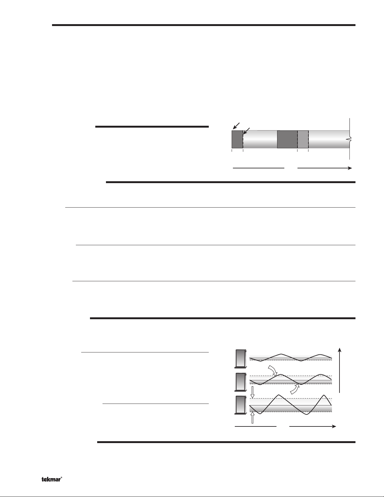
FIRE DELAY (FIRE DLY)
The FIRE DLY is the delay time that may occur between the time that the
664 closes a stage contact and the burner fi res for that stage. This delay
is usually the result of burner pre-purge or other forms of time delay built
into the burner’s safety circuits.
Boiler Contact Closes
Fire
Delay
Boiler Fires
Minimum
On Time
Minimum
Off Time
Time
Fire
Delay
Minimum
On Time
BOILER MASS (Boil MASS)
The Boil MASS setting allows the 664 to adjust to different types of heat sources depending on their thermal mass.
Light (LITE)
The LITE setting is selected if the boiler(s) that is used has a low thermal mass. This means that the boiler(s) has a very small
water content and has very little metal in the heat exchanger. A boiler that has a low thermal mass comes up to temperature quite
rapidly when fi red. This is typical of many copper fi n-tube boilers.
Medium (MED)
The MED setting is selected if the boiler(s) that is used has a medium thermal mass. This means that the boiler(s) either has
a large water content and a low metal content or a low water content and a high metal content. This is typical of many modern
residential cast iron boilers or steel tube boilers.
Heavy (HEVY)
The HEVY setting is selected if the boiler(s) that is used has a high thermal mass. This means that the boiler(s) has both a large
water content and a large metal content. A boiler that has a high thermal mass is relatively slow in coming up to temperature. This
is typical of many commercial cast iron and steel tube boilers.
DIFFERENTIAL (DIFF)
An on / off heat source such as a boiler must be operated with a differential in order to prevent short cycling. With the 664, either a
fi xed or an automatic differential may be selected.
Fixed Differential
The differential is centered around the target temperature. If the
temperature drops 1/2 the differential below the target temperature, the
664 closes the Boiler contact(s) to fi re the boiler(s). If the temperature
rises 1/2 of the differential above the target temperature, the 664 opens
the Boiler contact(s) to turn off the boiler(s).
Off
Differential
On
Auto Differential (AUTO)
If the AUTO Differential is selected, the 664 automatically adjusts
the Differential setting under the current load conditions to avoid
short cycling.
Time
STAGE 1 AND 2 (STAGE)
The Stage 1 and 2 setting may be selected to AUTO or OFF. When AUTO is selected, the stage is activated and the control
operates the appropriate boiler. When OFF is selected, the control does not fi re the stage.
© 2009 D 664 - 07/09
8 of 36
Heating Load
Page 9
ROTATION (ROTATE)
The ROTATE item is an adjustable setting that is factory set at 48 hours. The firing order of the boiler changes whenever one stage’s
accumulated running time exceeds the other stage’s accumulated running time by more than the ROTATE setting. After each rotation,
the stage with the least running hours is the fi rst to fi re and the stage with the most running hours is the last to fi re. This function
ensures that both stages receive equal amounts of use. When this item is set to the OFF setting, Stage 1 is always the fi rst to fi re.
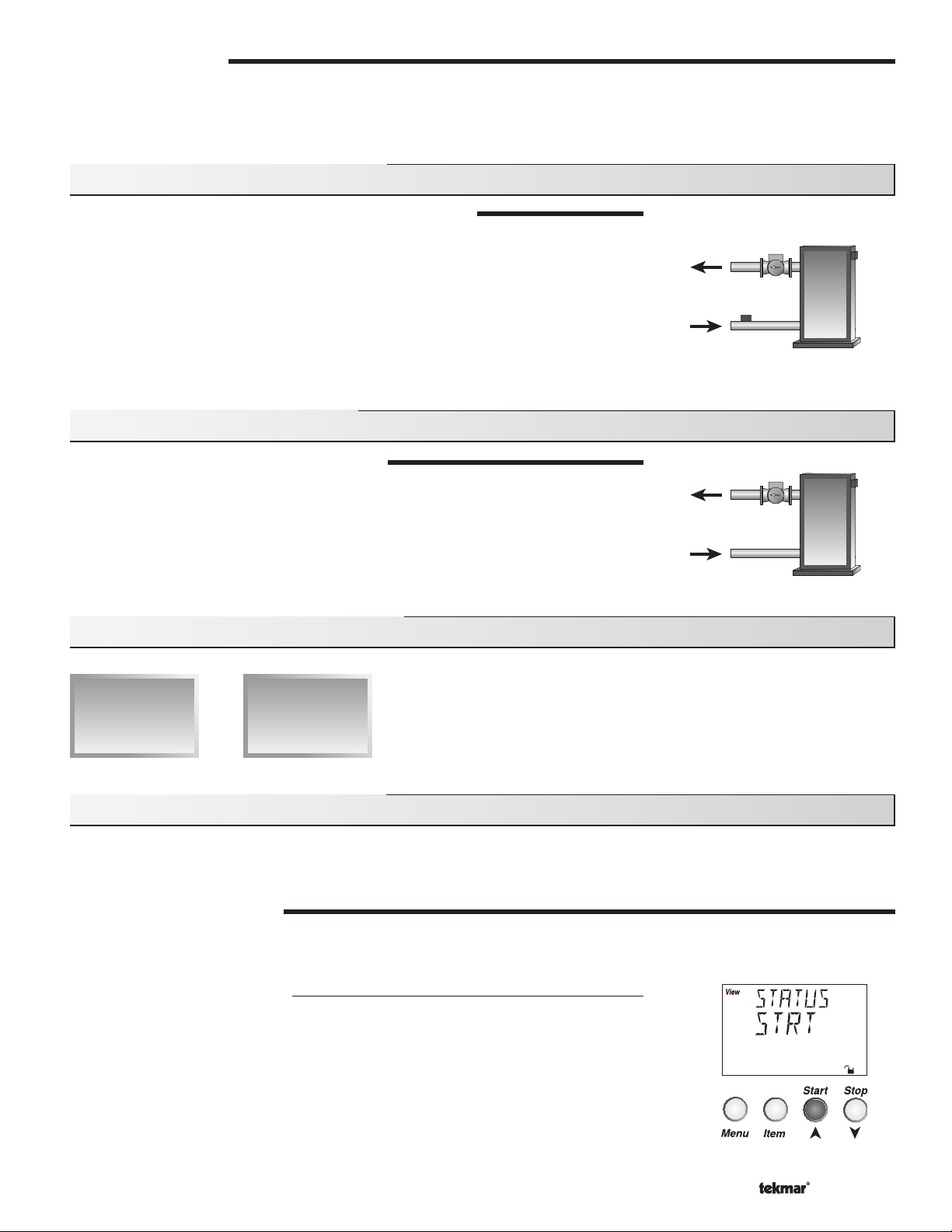
Section C2: Boiler Return Sensor
BOILER SENSOR ON THE RETURN (Boil SENS = RET)
The boiler sensor should be located on the boiler return if the 664 is one of many controls
that can call for boiler operation. When in the Return mode, the 664 provides a boiler
enable through the Stage 1 contact. The 664 no longer tries to control the boiler supply
water temperature directly, but allows the boiler to operate at its operating aquastat setting
when required. If this mode of operation is selected, the boiler pump should either operate
continuously, or be operated in parallel with the System Pump contact (Sys P1). When
the mixing device begins to ramp up, the Stage 1 contact closes on the 664. The Stage 1
contact remains closed until the mixing device no longer requires heat. With the sensor
on the boiler return, the 664 is still capable of providing boiler protection as described in
Section A.
Section C3: No Boiler Sensor
NO BOILER SENSOR (Boil SENS = NONE)
The 664 is capable of operating without a boiler sensor if desired. Without a boiler sensor,
the 664 is unable to provide boiler protection. In this mode of operation, the Stage 1 contact
is used to provide a boiler enable. When the mixing device begins to ramp up, the Stage 1
contact on the 664 closes. The Stage 1 contact remains closed until the mixing device no
longer requires heat. This type of application is typical if the 664 is drawing heat from a
source that already incorporates some form of boiler protection.
Section D: Melting Enable / Disable
Section D1
Snow Melting
Enable
Section D2
Snow Melting
Disable
Section D1: Snow Melting Enable
The snow melting system can be enabled manually or automatically. A melting enable signal applied to the control places both zones
into the Melting mode. If a melting enable signal is applied once the system is already in the Melting mode, the control responds to
the last command received.
MANUAL MELTING ENABLE
A manual melting enable signal requires the user to manually start the snow melting system and can be provided from the Start button
on the control, Remote Start / Stop Module 039, Remote Display Module 040, or an external melt demand.
Start Button on the Control
The snow melting system is enabled by pressing the Start button on the control while
in the VIEW menu. The control then displays the RUN TIME setting to allow the user to
adjust it. Once the snow melting system is enabled, the word STRT is displayed for at
least 5 seconds in the STATUS item of the appropriate zone while in the VIEW menu. If
the Start button on the control is pressed while the zone(s) is already melting and up to
temperature, the running time counter is reset to the RUN TIME setting.
© 2009 D 664 - 07/09
9 of 36
Page 10
Remote Start / Stop Module 039
The snow melting system is enabled by pressing the button on the front of the 039. While
the zone(s) is coming up to temperature, a green indicator light fl ashes on the front of
the 039. Once the zone(s) is up to temperature and the RUN TIME is counting down, the
green indicator light on the front of the 039 is on solid.
Remote Display Module 040
The snow melting system is enabled by pressing the ▲ button on the 040 while in the
VIEW menu. The 040 then displays the RUN TIME setting to allow the user to adjust
it. Once the snow melting system is enabled, the word STRT is displayed for at least 5
seconds in the Status item of the appropriate zone while in the VIEW menu.
External Melt Demand (DIP switch set to Melt Demand)
The snow melting system is enabled when a voltage between 24 and 240 V (ac) is applied
across the Melt / Idle Demand terminals (19 and 20). An external melt demand must be
present for at least 4 seconds in order to start the snow melting system. If the RUN TIME
reaches 0:00 and the external melt demand is still present, the control continues melting
until the external melt demand is removed or the system is otherwise stopped.
Note: This operation only occurs if the Idle Demand / Melt Demand DIP switch is set to
the Melt Demand position.
24 to 230 V (ac)
L
N
7
9
8
Start / Stop
19
Melt / Idle
Demand
StopStart
20
Idle Demand
Melt Demand
AUTOMATIC MELTING ENABLE (Snow / Ice Sensor 090)
The 664 can use the Snow / Ice Sensor 090 to provide an automatic melting enable signal
to start the snow melting system. The control continually monitors the 090 for the presence
of moisture. Once moisture is detected, the Water pointer is displayed in the LCD and the
snow melting system is enabled.
Note: In addition to the Snow / Ice Sensor 090 connected to the 664, the Zone 1 item in the
ADJUST menu must be set to AUTO in order for the automatic melting enable function to
work. Therefore, if zone 1 is turned off, the 090 can not provide a melting enable signal to
start the Melting mode for zone 2.
Water Detection Sensitivity (SENSTVTY)
The 664 has a Sensitivity setting which compensates for varying outdoor conditions which could affect how the moisture detector
in the 090 interprets the presence of moisture. This adjustable setting is available through the SENSTVTY item in the ADJUST
menu of the control. As snow becomes contaminated with dirt, and as the sensor itself becomes dirty, the control may incorrectly
indicate the presence of water. If this condition occurs, clean the surface of the sensor and / or turn down the SENSTVTY setting. If
the snow in your area is very clean, the SENSTVTY setting may need to be increased before snow is detected. If AUTO is selected,
the control automatically adjusts the sensitivity level used to detect moisture.
© 2009 D 664 - 07/09
10 of 36
Page 11
Section D2: Snow Melting Disable
The snow melting system can be disabled manually or automatically. A melting disable signal applied to the control takes both zones
out of the Melting mode. Once the snow melting system is disabled, the zone(s) operates in the Idling mode. The Idling mode allows the
zone(s) to be either operated at a lower temperature or turned off.
MANUAL MELTING DISABLE
A manual melting disable signal requires the user to manually stop the snow melting system and can be provided from the Stop
button on the control, Remote Start / Stop Module 039, Remote Display Module 040, or an external idle demand.
Stop Button on the Control
The Stop button on the control can be used to stop the snow melting system. The snow melting system is disabled by pressing
the Stop button on the control while in the VIEW menu. Once the snow melting system is disabled, the word STOP is displayed for
5 seconds in the STATUS item of the appropriate zone while in the VIEW menu.
Remote Start / Stop Module 039
A Remote Start / Stop Module 039 can be used to stop the snow melting system. The snow melting system is disabled by
pressing the button on the face of the 039. When the system is stopped, a solid red indicator light is displayed on the face of the
039 for fi ve seconds. If the snow melting system is disabled while there is still an external melt demand for snow melting, the 039
displays a solid red indicator light until the external demand is removed.
Remote Display Module 040
A Remote Display Module 040 can be used to stop the snow melting system. The snow melting system is disabled by pressing
the
▼ button on the 040 while in the VIEW menu. Once the snow melting system is disabled, the word STOP is displayed for 5
seconds in the STATUS item of the appropriate zone while in the VIEW menu.
20
External Idle Demand (DIP switch set to Idle Demand)
The snow melting system is disabled when a voltage between 24 and 230 V (ac) is
applied across the Melt / Idle Demand terminals (19 and 20). An external idle demand
must be present for at least 4 seconds in order to stop the snow melting system.
Note: This operation only occurs if the Idle Demand / Melt Demand DIP switch is set to
the Idle Demand position.
24 to 230 V (ac)
L
N
19
Melt / Idle
Demand
If the snow melting system is placed into Idling mode by an external idle demand, then
a manual melting enable signal is applied, the idle demand is overridden until either the
running time has expired, a stop signal is given, or the external idle demand is removed
and reapplied.
Idle Demand
Melt Demand
AUTOMATIC MELTING DISABLE (Snow / Ice Sensor 090)
The Snow / Ice Sensor 090 can be used to automatically disable the snow melting system. Once the 090 is dry, the Water pointer
turns off in the LCD. The zone 1 slab temperature has to be at least the zone 1 slab target temperature for a minimum of thirty
minutes in order for zone 1 to turn off. If a manual melting disable signal is applied and the 090 is dry, the snow melting system
turns off immediately.
© 2009 D 664 - 07/09
11 of 3 6
Page 12

Section E: Melting Operation
Section E1
General Melting
Operation
Section E1: General Melting Operation
The Snow Detector and Melting Control 664 provides up to two zones of snow melting. In order for the snow melting system to be
started, one of the methods described in Section D1 must be used. Once a melting enable signal is applied and the zone(s) is not in
WWSD or the system is not in CWCO, the Melting mode begins. When the control is in the Melting mode, the Melting pointer is visible
in the VIEW menu. The MELT 1 and the MELT 2 settings in the ADJUST menu sets the slab surface temperatures of zone 1 and zone
2 respectively. When the zone(s) is melting and its slab temperature is warming up to its slab target temperature, STRT is displayed in
the STATUS item of the appropriate zone while in the VIEW menu. The zone(s) fi nishes melting when its slab temperature has been
at least its slab target temperature for a period of time. This period of time is based on whether an automatic or manual melting enable
signal starts the snow melting system.
If an automatic melting enable signal starts the snow melting system, DET is displayed in the STATUS item of the appropriate zone
while in the VIEW menu once the slab temperature of the currently operating zone(s) reaches its slab target temperature. The currently
operating zone(s) continues to melt either until the 090 becomes dry, or any additional running time has expired. Once the Melting mode
is complete, the zone(s) operates in the Idling mode.
If a manual melting enable signal starts the snow melting system, the running time is displayed in the STATUS item of the appropriate
zone while in the VIEW menu and begins counting down once the slab temperature of the currently operating zone(s) reaches its slab
target temperature. The currently operating zone(s) continues to melt until the running time counts down to 0:00. Once the Melting mode
is complete, the zone(s) operates in the Idling mode. The table on page 14 describes how the control responds to enable and disable
signals.
ZONE 1 and 2 (ZONE)
The Zone 1 and 2 setting may be selected to AUTO or OFF. When AUTO is selected, the zone is activated and the control operates
the appropriate zone. When OFF is selected, the control does not operate the zone.
SLAB TEMPERATURE CONTROL
The 664 uses a sensor in zone 1 and zone 2 to provide slab temperature control. Zone 1 has the option to use either the Snow / Ice
Sensor 090 or the Slab Sensor. Zone 2 can only use the Slab Sensor.
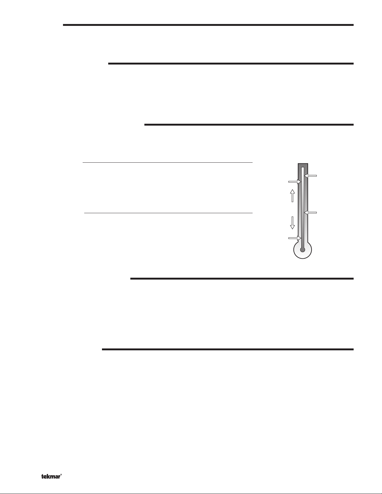
Slab Sensor
If a Slab Sensor is used, the control assumes that the sensor is
approximately 1 inch below the surface of the snow melting slab. Since
this point is closer to the source of the heat, this point is warmer than
the surface of the slab. Therefore, the sensor must be maintained at
a higher temperature in order to ensure that the surface of the slab
is maintained at the correct temperature. The amount of temperature
difference between the surface of the slab and the slab sensor changes
with the outdoor temperature. Therefore, the slab core temperature
is increased as the outdoor air temperature drops. The temperature
displayed as the slab temperature (SLAB 1 and / or SLAB 2) is the
temperature of the slab sensor.
Snow / Ice Sensor 090
The temperature displayed as the slab temperature (SLAB 1) is the
slab temperature of zone 1. This temperature is calculated from the
edge sensor and the center sensor built into the 090.
Surface temperature = 35°F
Core (sensor)
is warmer
Slab Outdoor ResetSlab Outdoor Reset
Decreasing Air Temperature
Slab Surface Temperature is Constant
Increasing Slab Core Temperature
SLAB TARGET TEMPERATURE (SLB TRG)
The SLB1 TRG and the SLB2 TRG temperatures are determined from the Melting settings (MELT 1 and MELT 2 respectively),
or Idle settings (IDLE 1 and IDLE 2 respectively) and the outdoor air temperature. The control displays the temperature(s) that it is
currently trying to maintain at the slab sensors of zone 1 and zone 2. If the control does not presently have a requirement for heat, it
displays “– – –” in the STATUS item of the appropriate zone while in the VIEW menu.
© 2009 D 664 - 07/09
12 of 36
Page 13

ADDITIONAL MELTING TIME (ADD MELT)
In cases where areas of the snow melting system haven’t completely
melted after the Melting mode has fi nished and the 090 is dry, the 664 has
a function in which additional time can be added to melt the zone(s). This
is an adjustable time through the ADD MELT item in the ADJUST menu of
the control. The ADD MELT time is calculated into a running time and is
displayed in the STATUS item of the appropriate zone while in the VIEW
menu. Once the 090 becomes dry and the currently operating zone(s)
slab temperature is at least its slab target temperature, the running time
starts counting down.
Note: This function is only available if the Snow / Ice Sensor 090 is used
in zone 1.
PRIORITY OPERATION
In a multiple zone system where the zones have different heat
requirements, or the total combined heat requirement of the snow melting
system exceeds that of the heat source, the 664 has a function which
can provide priority of zone 1 over zone 2. The 664 allows for full priority,
conditional priority or no priority. This is a selectable item through the
PRIORITY item in the ADJUST menu.
Note: If either Full Priority or Conditional Priority is selected, there is the
potential for the non-priority zone to freeze over.
Zone 2
Zone 1
Snow Ice Sensor
Zone 1 melts
before Zone 2
Dry
Full Priority (PRIORITY = FULL)
It can be selected that zone 1 has full priority over zone 2. Zone 1 begins melting first when the Melting mode is initiated. While
zone 1 is melting, the control keeps track of how long zone 1 operates at its melting temperature. Once zone 1 fi nishes melting, the
control turns off zone 1 and starts melting zone 2. Zone 2 then operates at its melting temperature for the same amount of melting
time as zone 1. If at any time while zone 2 is melting and the system is restarted either manually or automatically, the control turns
off zone 2 and begins melting zone 1. If the slab temperature of zone 2 is warm enough when the system is restarted, the control
provides any extra heat to zone 2 that zone 1 is not using. If the slab temperature of zone 2 is not warm enough when the system
is restarted, the control only provides heat to zone 1. Zone 2 then only receives heat when zone 1 fi nishes melting.
Conditional Priority (PRIORITY = COND)
It can be selected that zone 1 has conditional priority over zone 2. Zone 1 begins melting first when the Melting mode is initiated.
While zone 1 is melting and up to temperature, the control provides any extra heat to zone 2 that zone 1 is not using. While zone 1
is melting, the control keeps track of how long zone 1 operates at its melting temperature. Once zone 1 fi nishes melting, the control
turns off zone 1 and provides all available heat to zone 2. Zone 2 then operates at its melting temperature for the same amount of
melting time as zone 1. If at any time while zone 2 is melting and the system is restarted either automatically or manually, the control
turns off zone 2 and begins melting zone 1 again. The control then operates zone 1 and zone 2 as described above.
Zone 2
Zone 1
NON-PRIORITY OPERATION (PRIORITY = NONE)
If the PRIORITY item is set to NONE, zone 1 and zone 2 begin melting
simultaneously when the Melting mode is initiated. The 664 operates
based on the mixing fl uid temperature requirement of each zone. The
mixing target temperature is calculated for the zone with the highest heat
requirement, and that zone output runs continuously. The zone output
with the lower heat requirement is cycled using Pulse Width Modulation
(PWM) with a 20 minute cycle length.
Zone 1 and
Zone 2 melt
simultaneously
© 2009 D 664 - 07/09
13 of 36
Page 14

Section F: Idling Operation
Section F1
General Idling
Operation
Section F2
Temporary
Idle
Section F1: General Idling Operation
When the snow melting system starts from a cold temperature, the time required for the zone(s) to reach its melting temperature may
be excessive. To decrease this start up time, the 664 has an idling feature which can maintain the zone(s) at a lower temperature. This
feature is also useful for preventing frost and light ice formation. The IDLE 1 and the IDLE 2 settings in the ADJUST menu sets the slab
surface temperatures of zone 1 and zone 2 respectively while the control is in the Idling mode. When in the Idling mode, IDLE 1 and / or
IDLE 2 is displayed in the STATUS item of the appropriate zone while in the VIEW menu. If idling is not desirable, the IDLE 1 and / or
IDLE 2 settings may be set to OFF.
IDLING WITHOUT PRIORITY
If the PRIORITY item is set to NONE, both zone 1 and zone 2 can utilize the idling feature.
IDLING WITH PRIORITY
If the PRIORITY item is set to COND or FULL, only zone 1 can utilize the idling feature. Therefore, the IDLE 2 item in the ADJUST
menu is not available.
Section F2: Temporary Idle (TMPY IDL)
The temporary idle allows the control to enter the idle state for a set amount of time. If the snow ice detector does not detect snow
during the temporary idle period, the control then leaves the idle state and returns to the OFF state. This is useful in applications
where there is the possibility of snow and the slab can be pre-heated in order to have a short heat up time if snow is detected.
To enable a temporary idle, the Tempora ry Idle setting in the ADJUST menu must be set from OFF to the length of the temporary idle.
The DIP Switch must be set to IDLE DEMAND and the IDLE 1 or IDLE 2 settings must be set to a temperature. To activate a temporary
idle, a voltage between 24 and 240 V (ac) must be applied across the Melt/Idle Demand terminals for at least 4 seconds.
When a Tem porary Idle time is selected, the control has three available states: OFF, Temporary Idle, and Melting. The table below
describes the action of the control:
Control State Action Result
OFF External Idle Demand Temporary Idle
OFF Manual or Auto Melt Start Melting
Melting External Idle Demand Melting
Melting Manual or Auto Melt Start Melting
Melting Manual or Auto Melt Stop OFF
Temporary Idle Temporary Idle Expires OFF
Temporary Idle Manual or Auto Melt Start Melting
Temporary Idle Manual Melt Stop OFF
© 2009 D 664 - 07/09
14 of 36
Page 15

Installation
CAUTION
Improper installation and operation of this control could result in damage to the equipment and possibly even personal injury. It is your
responsibility to ensure that this control is safely installed to all applicable codes and standards. This electronic control is not intended
for use as a primary limit control. Other controls that are intended and certifi ed as safety limits must be placed into the control circuit.
Do not open the control. Refer to qualifi ed personnel for servicing. Opening voids warranty and can result in damage to the equipment
and possibly even personal injury.
STEP ONE
Check the contents of this package. If any of the contents listed are missing or damaged, please contact your wholesaler or tekmar
sales representative for assistance.
Type 664 includes: One Snow Detector and Melting Control 664, One Outdoor Sensor 070, Three Universal Sensors 082,
Note: Carefully read the details of the Sequence of Operation to ensure that you have chosen the proper control for
your application.
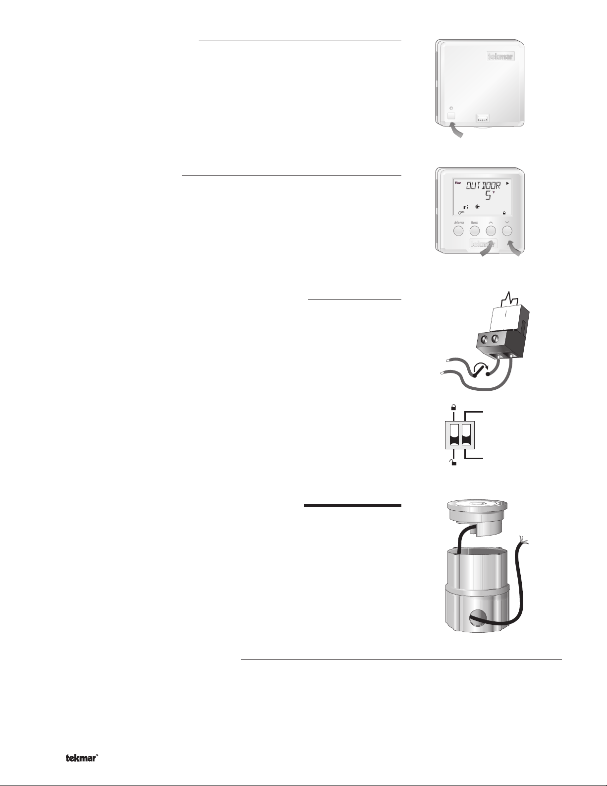
STEP TWO
Remove the control from its base by pressing down on the release clip in the wiring chamber and sliding the control away from it.
The base is then mounted in accordance with the instructions in the Data Brochure D 001.
STEP THREE
All electrical wiring terminates in the control base wiring chamber. The base has standard 7/8” (22 mm) knockouts which accept
common wiring hardware and conduit fittings. Before removing the knockouts, check the wiring diagram and select those sections
of the chamber with common voltages. Do not allow the wiring to cross between sections as the wires will interfere with safety
dividers which should be installed at a later time.
• Power must not be applied to any of the wires during the rough-in wiring stage.
• All wires are to be stripped to a length of 3/8” (9mm) to ensure proper connection to the control.
• Install the Outdoor Sensor 070, Boiler Sensor 082 and Mixing Sensor(s) 082 according to the installation instructions in the Data
Brochure D 070 and run the wiring back to the control.
• Install the Snow / Ice Sensor 090 according to the installation instructions in the Data Brochure D 090 and run the wiring back
to the control. See Data Brochure D 090 for very important details on sensor location and installation.
• If a Slab Sensor is used, install the slab sensor according to the installation instructions in the Data Brochure D 079 and run the
wiring back to the control. See page 12 for very important details on sensor location and installation.
• If a Remote Display Module (RDM) 040 is used, install the RDM according to the installation instructions in the Data Brochure
D 040 and run the wiring back to the control.
• If a Remote Start / Stop Module 039 is used, install the module according to the installation instructions in the Data Brochure
D 039 and run the wiring back to the control.
• Run wire from other system components (pumps, boiler, etc.) to the control.
• Run wires from the 115 V (ac) power to the control. Use a clean power source with a minimum 15 A circuit to ensure proper
operation. Multi-strand 16 AWG wire is recommended for all 115 V (ac) wiring due to its superior flexibility and ease of installation
into the terminals.
–––––––––––
Data Brochures D 664, D 070, D 001, User Brochure U 664, Application Brochure A 664, Essay E 021.
––––––––––
–––––––––
GETTING READY
MOUNTING THE BASE
ROUGH-IN WIRING
STEP FOUR
The installer should test to confirm that no voltage is present at any of the wires. Push the control into the base and slide it down
until it snaps firmly into place.
Powered Input Connections
115 V (ac) Power
Connect the 115 V (ac) power supply to the Power L and Power N terminals (29 and
30). This connection provides power to the microprocessor and display of the control.
As well, this connection provides power to the Sys P1 terminal (28) from the Power L
terminal (29).
© 2009 D 664 - 07/09
15 of 36
––––––––––
ELECTRICAL CONNECTIONS TO THE CONTROL
115 V (ac)
L
N
29
Power
L
30
N
Page 16

Melt / Idle Demand
To generate a melt demand or idle demand, a voltage between
24 V (ac) and 230 V (ac) must be applied across the Melt / Idle
Demand terminals (19 and 20).
Output Connections
24 to 230 V (ac)
L
N
19
Melt / Idle
Demand
20
Boiler Contacts
The Stage 1 and Stage 2 terminals (21, 22 and 23, 24) are isolated
outputs in the 664. There is no power available on these terminals
from the control. These terminals are used as a switch to either make
or break the boiler circuit. When the 664 requires the boiler(s) to fi re, it
closes the contact between terminals 21 and 22 and / or 23 and 24.
System Pump Contact (Sys P1)
The Sys P1 output terminal (28) on the 664 is a powered output.
When the relay in the 664 closes, 115 V (ac) is provided to the Sys P1
terminal (28) from the Power L terminal (29). To operate the system
pump, connect one side of the system pump circuit to terminal 28
and the second side of the pump circuit to the neutral (N) side of the
115 V (ac) power supply.
Zone Pumps and Zone Valves
The zoning outputs are isolated terminals in the 664. There is no
power available on these terminals from the control.
If zone 1 is used, connect the zone pump or zone valve circuit to the
Com Zn and Zn 1 terminals (26 and 25).
N
115 V (ac)
24 to 230 V (ac)
21
N
M
L
Stage
1
OR
28
Sys
P1
25
Zn
1
Stage
2
29
Power
L
26
Com
Zn
30
N
L
24
23
22
If zone 2 is used, connect the zone pump or zone valve circuit to the
Com Zn and Zn 2 terminals (26 and 27).
Variable Speed Injection Pump
The 664 can vary the speed of a permanent capacitor, impedance
protected or equivalent pump motor that has a locked rotor current
of less than 2.4 A. Most small wet rotor circulators are suitable as
described in Essay E 021. The 664 has an internal overload fuse which
is rated at 2.5 A 250 V (ac). Contact your tekmar sales representative
for details on the repair procedures if the fuse is blown.
If a variable speed injection pump is used, connect one of the wires
from the variable speed injection pump to the Opn / Var terminal (3)
on the 664. Connect the Pwr Mix terminal (4) to the live (L) side of
the 115 V (ac) power source. The other wire on the variable speed
injection pump must be connected to the neutral (N) side of the
115 V (ac) power supply.
© 2009 D 664 - 07/09
16 of 36
24 to 230 V (ac)
L
N
M
OR
115 V (ac)
N
L
Com
Opn/
Var
26
Zn
27
Zn
2
4
3
Pwr
Mix
Page 17

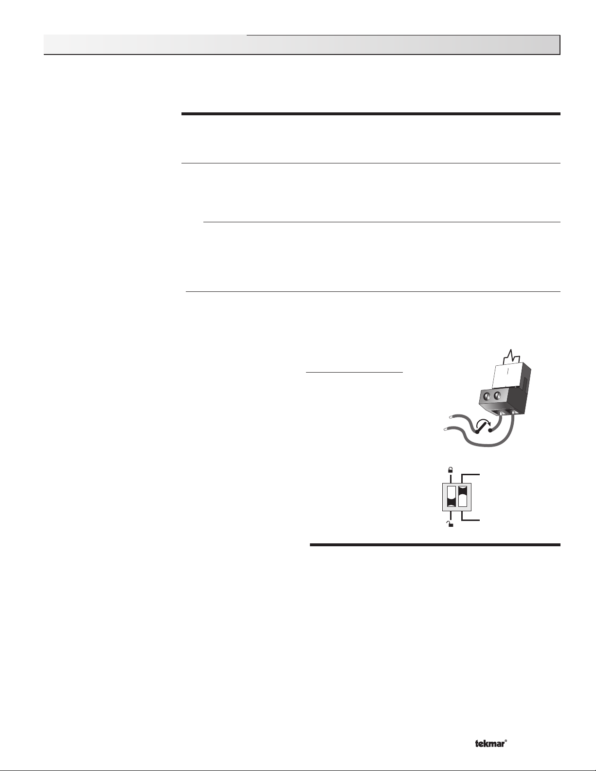
Mixing Valve Actuator
5
If a mixing valve is used, connect one side of the 24 V (ac) power to
the Pwr Mix terminal (4) on the control. The output relay Opn / Var
(3) is then connected to the open terminal of the actuating motor
and the output relay Cls (5) is connected to the close terminal of the
24 to 115 V (ac)
Opn/
Var
4
3
Cls
Pwr
Mix
actuating motor. Connect the second side of the 24 V (ac) circuit to
the common terminal of the actuating motor.
R
C
4-20 mA Device
If a 4-20 mA device is used, connect the positive 4-20 mA lead to the 4-20 mA + terminal (1) and the negative 4–20 mA
lead to the 4-20 mA – terminal (2). Maximum resistance allowed in the 4-20 mA circuit is 1000 Ω. The 4-20 mA output can
be converted to either a 2-10 V (dc) or 1-5 V (dc) output by connecting resistor(s). A 0-135 Ω Converter 005 can be used to
convert the 4-20 mA signal to 0-135 Ω.
1
4-20 mA
+
–
+
4-20 mA
uating Motor
Act
Connection to Operate
a 4 - 20 mA Device
B
1
4-20 mA
+
R
W
2
–
2
2
–
1-5 Vdc or 2-10 Vdc Device
1
4 - 20 mA
–
+
–
+
0-10 Vdc
Actuating Motor
Converting the 4-20 mA
Output to Operate a
500Ω resistor
4-20 mA converted
to 2-10 Vdc output
OR
250Ω resistor
4-20 mA converted
to 1-5 Vdc output
Modutrol IV
B
R
W
+
-
tekmar
Converting the 4-20 mA
Output to Operate a
0-135 Ω Actuating Motor
V9055
B
R
W
+
-
tekmar
Sensor and Unpowered Input Connections
Do not apply power to these terminals as this will damage the
control.
Outdoor Sensor
Connect the two wires from the Outdoor Sensor 070 to the Com and
Out terminals (16 and 18). The outdoor sensor is used by the 664 to
measure the outdoor air temperature.
Boiler Sensor
Connect the two wires from the Boiler Sensor 082 to the Com and
Boil terminals (16 and 17). The boiler sensor is used by the 664 to
measure the water temperature of the boiler.
Mixing Supply Sensor
Connect the two wires from the Mixing Supply Sensor 082 to the
Com and Mix Sup terminals (12 and 15). The mixing supply sensor
is used by the 664 to measure the fl uid supply temperature after the
mixing device. Normally the sensor is attached downstream of the
mixing pump.
Mixing Return Sensor
Connect the two wires from the Mixing Return Sensor 082 to the
Com and Mix Ret terminals (12 and 14). The mixing return sensor
is used by the 664 to measure the fl uid return temperature from the
snow melting slab.
Boiler
Sensor
Mix Supply
Sensor
Mix Return
Sensor
System
Pump
12
Com
16
Com
12
Com
17
Boil
16
Com
13
tN2
18
Out
17
Boil
15
14
Mix
Mix
Sup
Ret
14
13
Mix
tN2
Ret
© 2009 D 664 - 07/09
17 of 36
Page 18

EITHER: Snow / Ice Sensor 090 (Zone 1)
If a Snow / Ice Sensor 090 is used, connect the red wire from the
sensor cable to the Red terminal (6), connect the black wire from the
sensor cable to the Blk / Com terminal (7), connect the blue wire from
the sensor cable to the Blu terminal (8), connect the yellow wire from
the sensor cable to the Yel terminal (9) and connect the brown wire
from the sensor cable to the Brn / Slab1 terminal (10). The snow / ice
sensor is used by the 664 to measure the slab surface temperature
of zone 1. This sensor must be installed fl ush with the slab surface
and 1/2 way between the heating pipes. See Data Brochure D 090
for installation instructions regarding the Snow / Ice Sensor 090 and
Sensor Socket 091.
Red
6
Blk/
Com
Blu
Brn/
Yel
Slab1
10
9
8
7
OR: Slab Sensor (Zone 1)
If a Snow / Ice Sensor 090 is not used for zone 1, a slab sensor
can be used. If a slab sensor is used, connect the two wires from
the slab sensor to the Blk / Com and Brn / SLAB 1 terminals (7
and 10). The slab sensor is used by the 664 to measure the slab
temperature of zone 1.
Note: Proper sensor placement is critical for correct operation of the
664 control. The slab sensor must be installed 1/2 way between the
heating pipes and 1’’ (25 mm) below the surface of the slab. Although
the sensor can be installed directly into the slab, we recommend that
the sensor be installed in tubing or conduit in such a manner that the
sensor can be removed and replaced in case of failure.
Slab Sensor (Zone 2 )
If a slab sensor is used, connect the two wires from the slab sensor
to the Slab 2 and Com terminals (11 and 12). The slab sensor is used
by the 664 to measure the slab temperature of zone 2.
tekmar Net™ (tN2) Device
A Remote Display Module (RDM) 040 or Remote Start / Stop
Module 039 can be connected to the tekmar Net™ (tN2) input.
Connect the Com terminal from the appropriate tN2 device to the
Com terminal (12) on the 664. Connect the tN2 terminal from the
appropriate tN2 device to the tN2 terminal (13) on the 664.
Note: The wires from the RDM and Remote Start / Stop Module are
polarity sensitive. The tN2 device does not operate correctly if the
wires are reversed.
OR
Blk/
Com
7
Blu
Slab
Yel
11
2
12
Brn/
Slab1
12
Com
13
10
9
8
STEP FIVE
TESTING THE WIRING
Each terminal block must be unplugged from its header on the control before power is applied for testing. To remove the terminal
block, pull straight down from the control.
The following tests are to be performed using standard testing practices and procedures and should only be carried out by properly
trained and experienced persons.
A good quality electrical test meter, capable of reading from at least 0 – 300 V (ac) and at least 0 – 2,000,000 , is essential to
properly test the wiring and sensors.
Test The Sensors
17
In order to test the sensors, the actual temperature at each sensor
location must be measured. A good quality digital thermometer with
a surface temperature probe is recommended for ease of use and
accuracy. Where a digital thermometer is not available, a spare sensor
can be strapped alongside the one to be tested and the readings
compared. Test the sensors according to the instructions in the Data
Brochure D 070.
© 2009 D 664 - 07/09
18 of 36
16
Com
Boil
Page 19

Test The Power Supply
Make sure exposed wires and bare terminals are not in contact with
other wires or grounded surfaces. Turn on the power and measure
the voltage between the Power L and Power N terminals (29 and 30)
using an AC voltmeter, the reading should be between 103.5 and
126.5 V (ac).
Test The Powered Inputs
V
29
L
Power
30
N
103.5 to 126.5 V (ac)
Melt / Idle Demand
If a melt / idle demand is used, measure the voltage between the
19
Melt/Idle
Demand
20
20 to 260 V (ac)
Melt / Idle Demand terminals (19 and 20). When the melting or idling
device calls for heat, you should measure between 20 and 260 V (ac)
at the terminals. When the melting or idling device is off, you should
measure less than 5 V (ac).
Test The Outputs
30
29
28
System Pump (Sys P1)
If a system pump is connected to the Sys P1 terminal (28), make sure
Sys
P1
Power
L
N
that power to the terminal block is off and install a jumper between the
Sys P1 and Power L terminals (28 and 29). When power is applied
to the Power L and Power N terminals (29 and 30), the system
pump should start. If the pump does not turn on, check the wiring
L
between the terminal block and pump and refer to any installation
or troubleshooting information supplied with the pump. If the pump
operates properly, disconnect the power and remove the jumper.
N
115 V (ac)
Zone Pump or Zone Valve
If a zone pump or zone valve is connected to the Com Zn and Zn 1 terminals (26 and 25), make sure power to the pump or valve
circuit is off and install a jumper between the Com Zn and Zn 1 terminals (26 and 25). When the circuit is powered up, the zone
pump should turn on or the valve should open completely. If no response occurs, check the wiring between the terminal and the
pump or valve and refer to any installation or troubleshooting information supplied with these devices. If a zone pump or zone
valve is connected to the Com Zn and Zn 2 terminals (26 and 27), follow a similar procedure as described for the zone 1 relay.
Stage 1 and 2
If the boiler circuit is connected to the Stage 1 terminals (21 and 22) and / or Stage 2 terminals (23 and 24), make sure power
to the boiler circuit is off, and install a jumper between the terminals. When the boiler circuit is powered up, the boiler should
fi re. If the boiler does not turn on, refer to any installation or troubleshooting information supplied with the boiler. (The boiler may
have a fl ow switch that prevents fi ring until the boiler pump is running). If the boiler operates properly, disconnect the power and
remove the jumper.
Variable Speed Injection Pump
If a variable speed injection pump circuit is connected to the Pwr Mix and Opn / Var terminals (4 and 3), make sure the power
to the terminal block is off and install a jumper between the Pwr Mix and Opn / Var terminals (4 and 3). When the variable speed
pump circuit is powered up, the variable speed pump should operate at full speed. If the pump does not operate, check the wiring
between the terminal block and the pump and refer to any installation or troubleshooting information supplied with the pump. If
the pump operates properly, disconnect the power and remove the jumper.
Mixing Valve Actuator
If a floating action actuating motor circuit is connected to the Pwr Mix, Opn / Var and Cls terminals (4, 3 and 5), make sure
power to the motor circuit is off and install a jumper between the Pwr Mix and Opn / Var terminals (4 and 3). When the circuit
is powered up, the actuator should move in the opening direction. If it does not, check the wiring between the terminals and
the actuating motor. Refer to any installation or troubleshooting information supplied with the motor. If the motor closes instead
of opening, the wiring of the actuating motor must be reversed. If the valve opens correctly, turn off the power to the circuit
and remove the jumper. Install a jumper between the Pwr Mix and Cls terminals (4 and 5). When the circuit is powered up, the
actuator should move in the closing direction. If it does not, check the wiring between the terminals and the actuating motor.
Refer to any installation or troubleshooting information supplied with the motor. If the motor closes correctly, turn off the power
to the circuit and remove the jumper.
© 2009 D 664 - 07/09
19 of 36
Page 20

4–20 mA Device
The 4–20 mA output terminals (1 and 2) can not be tested without power applied to the control. Since no power is supplied to
the control at this point, the 4–20 mA output cannot be tested. Please refer to the operation test below.
Connecting The Control
Make sure all power to the devices and terminal blocks is off, and
remove any remaining jumpers from the terminals. Reconnect the
terminal blocks to the control by carefully aligning them with their
respective headers on the control, and then pushing the terminal blocks
into the headers. The terminal blocks should snap fi rmly into place.
Install the supplied safety dividers between the unpowered sensor
inputs and the powered wiring chambers. Apply power to the control.
The operation of the control on power up is described in the Sequence
of Operation section of the brochure.
Test the 4-20 mA Output
If a 4-20 mA device is used, connect an ammeter to the 4-20 mA output
terminals (1 and 2) and observe the current reading during operation.
When the 4-20 mA modulation increases, the initial percentage output
is zero and the meter should read 4 mA. As the % Output increases, the
meter reading should increase until 100% Output is reached at which
point the meter should read 20 mA. When the 4-20 mA modulation
decreases, the meter should start at 20 mA and eventually reach 4 mA
when the display shows 0% Output.
Note: The 4-20 mA output can only be tested if 4-20 is selected in the
Mixing item of the ADJUST menu.
Cleaning
6.4 mA
Milli Amp
1
xxx
4 - 20 mA
+
2
xxx
–
Opn/
Var
Cls
Pwr
Mix
Test the 4-20 mA output
using a milliamp meter
1000 ma = 1 amp
1
4-20 mA
+
2
-
5
4
3
The control’s exterior can be cleaned using a damp cloth. Moisten cloth with water and wring out prior to wiping control. Do no use
solvents or cleaning solutions.
DIP Switch Settings
The DIP switch settings on the control are very important and should be set to the appropriate
settings prior to making an adjustments to the control through the User Interface. The DIP
switch settings change the items that are available to be viewed and / or adjusted in the User
Interface.
If a DIP switch is changed while the control is powered up, the control responds to the change
in setting by returning the display to the VIEW menu. This is true for all the DIP switches except
for the Lock / Unlock DIP switch.
LOCK / UNLOCK (FACTORY SETTING IS UNLOCK)
The Lock / Unlock DIP switch is used to lock and unlock the access level of the control and tekmar Net™ tN2 device. Once locked,
access levels can not be changed. To determine if the control is currently locked or unlocked, a small segment representing a padlock
is viewed in the bottom right hand corner of the display. When the padlock is closed, the access level cannot be changed.
To change the access level, set the DIP switch to the unlocked, or down position. The current access level of the control or
tekmar Net™ tN2 device is viewed in its Miscellaneous (Misc) menu. While viewing the access level, use the
between the Limited (LTD), User (USER), Installer (INST) or Advanced (ADV) access levels.
To lock the access level, select the appropriate access level in the Miscellaneous (Misc) and move the DIP switch from the unlocked
position to the locked position. As long as the DIP switch is in the locked position, the access level of the control or tekmar Net™ tN2
device can no longer be viewed or adjusted in its Miscellaneous (Misc) menu.
Idle Demand
Melt Demand
▲ and ▼ keys to select
IDLE DEMAND / MELT DEMAND (FACTORY SETTING IS MELT DEMAND)
The Idle Demand / Melt Demand DIP switch is used for melting and idling operation. The position of the DIP switch determines what
the Melt / Idle Demand terminals (19 and 20) are used for. When the DIP switch is set to the Melt Demand position, the Melt / Idle
Demand terminals (19 and 20) are used to place the snow melting system into Melting mode. When the DIP switch is set to the Idle
Demand position, the Melt / Idle Demand terminals (19 and 20) are used to force the snow melting system into Idling mode.
© 2009 D 664 - 07/09
20 of 36
Page 21

Access Levels
The tekmar Snow Detector and Melting Control 664 comes with four Access
Level settings. These Access Levels restrict the number of Menus, Items
and Adjustments that can be accessed by the user. The four access levels
are Limited (LTD), User (USER), Installer (INST) and Advanced (ADV).
The access level of the control is found in the Miscellaneous (Misc) menu
when the Lock / Unlock DIP switch is set to the Unlocked position. In the
Advanced access level, all of the control settings are available to the user.
In the User access level, only a few of the menus and items are available.
The Limited access level is the most restricted of them all. The control’s
factory setting is Installer (INST). This access level is suffi cient for the
normal set up of the control. Once the control is set up, the appropriate
access level should be selected for the people that deal with the control
on a regular basis.
© 2009 D 664 - 07/09
21 of 36
Page 22

664 View Menu (1 of 2)
Item Field
Section
LT D
USER
INST
Access
Level
ADV
Description
Range
E1
E1
B1
E1
E1
Outdoor Current outdoor air temperature as measured by
the outdoor sensor.
Slab 1 Target Slab sensor target temperature of zone 1.
ZONE 1 = AUTO
Slab 1 Current slab sensor temperature of zone 1.
ZONE 1 = AUTO
Status 1 Operating status of Zone 1.
Slab 2 Target Slab sensor target temperature of zone 2.
ZONE 2 = AUTO
Slab 2 Current slab sensor temperature of zone 2.
ZONE 2 = AUTO
-67 to 149°F
(-55 to 65°C)
– – –, -58 to 167°F
(– – –, -50 to 75°C)
-58 to 167°F
(-50 to 75°C)
STRT, STOP, IDLE, EXT,
0:00 to 23:59 hr, – – –,
INF, WWSD, CWCO,
DET, IDLE
– – –, -58 to 167°F
(– – –, -50 to 75°C)
-58 to 167°F
(-50 to 75°C)
B1
A
B1
B1
B1
Status 2 Operating status of zone 2.
Mix Target The current mix target temperature as calcu-
lated by the control.
Mix Supply Current mixed supply water temperature as
measured by the mixing supply sensor.
Mix Return Current mixed return water temperature as
measured by the mixing return sensor.
Mix Ret Sensor present
∆T Current mixed ∆T difference between the mixed supply
sensor and the mixed return sensor.
∆T MAX ≠ OFF
STRT, STOP, IDLE, EXT,
0:00 to 23:59 hr, – – –,
INF, WWSD, CWCO,
DET, IDLE
– – –, -25 to 248°F
(– – –, -32 to 120°C)
-31 to 266°F
(-35 to 130°C)
-31 to 266°F
(-35 to 130°C)
-85 to 170°F
(-47 to 94°C)
© 2009 D 664 - 07/09
22 of 36
Page 23

664 View Menu (2 of 2)
Item Field
Section
LT D
USER
INST
Access
Level
ADV
Description
Range
A
C1
A
C2
664 Adjust Menu (1 of 3)
Item Field
Section
B1
LT D
USER
INST
Boil Supply Current boiler supply water temperature as
measured by the boiler sensor.
Boil SENS = SUP
Boil Return Current boiler return water temperature as
measured by the boiler sensor.
Boil SENS = RET
Access
Level
ADV
Run Time The time for which a zone is operated
once it has reached its melting temperature. This
item cannot be viewed if a Remote Start / Stop
Module 039 has been connected.
Description
0:30 to 17:00 hr,
INF (Infi nity)
Default = 4:00 hr
-31 to 266°F
(-35 to 130°C)
-31 to 266°F
(-35 to 130°C)
Range
Actual
Setting
E1
D1
E1
E1
F1
E1
Add Melt The additional time for which a zone
is operated once the Snow / Ice Sensor 090
becomes dry.
090 is present
Sensitivity Sensitivity of water detection of the
Snow / Ice Sensor 090.
090 is present
Zone 1 Selects zone 1 as operational or not.
Melt 1 The desired slab surface temperature of
zone 1 while in the Melting mode.
Zone 1 = AUTO
Idle 1 The desired slab surface temperature of
zone 1 while in the Idling mode.
Zone 1 = AUTO
Zone 2 Selects zone 2 as operational or not.
0:00 to 6:00 hr
Default = 0:30 hr
AUTO, 20 to 80%
Default = AUTO
OFF, AUTO
Default = AUTO
32 to 95°F
(0 to 35°C)
Default = 36°F (2°C)
OFF, 20 to 95°F
(OFF, -7 to 35°C)
Default = OFF
OFF, AUTO
Default = OFF
© 2009 D 664 - 07/09
23 of 36
Page 24

664 Adjust Menu (2 of 3)
Item Field
Section
LT D
USER
INST
Access
Level
ADV
Description
Range
Actual
Setting
E1
F1
B
B1
E1
Melt 2 The desired slab surface temperature of
zone 2 while in the Melting mode.
Zone 2 = AUTO
Idle 2 The desired slab surface temperature of
zone 2 while in the Idling Mode.
Zone 2 = AUTO, PRIORITY = NONE
Temporary Idle Time for which the temporary
idle is active.
WWSD Warm Weather Shut Down. Slab must
exceed 34°F to enter WWSD.
CWCO The Cold Weather Cut Out temperature
for the snow melting system.
Priority Selects priority of zone 1 over zone 2.
∆T MAX = OFF
32 to 95°F
(0 to 35°C)
Default = 36°F (2°C)
OFF, 20 to 95°F
(OFF, -7 to 35°C)
Default = OFF
OFF, 0:30 to 40:00 hr
Default = OFF
AUTO, 32 to 95°F
(AUTO, 0 to 36°C)
Default = AUTO
OFF, -30 to 50°F
(OFF, -34 to 10°C)
Default = 10°F (-12°C)
NONE, COND, FULL
Default = COND
E1
A
A
A
C
Priority Selects priority of zone 1 over zone 2.
∆T MAX ≠ OFF
Mix Maximum The maximum supply water
temperature for the mixing system.
Mixing The type of mixing device that is to be used.
Motor Speed The time the actuating motor
requires to operate from fully closed to fully open.
MIXING = FLOT or MIXING = 4 – 20
Boiler Sensor The location of the boiler sensor.
This affects operation of the Boiler contact.
COND, FULL
Default = COND
80 to 210°F, OFF
(27 to 99°C, OFF)
Default = 150°F (66°C)
FLOT (Floating),
VAR (Variable Speed),
4 – 20 (4-20 mA)
Default = VAR
30 to 230 seconds
Default = 150 sec
SUP, RET, NONE
Default = SUP
© 2009 D 664 - 07/09
24 of 36
Page 25

664 Adjust Menu (3 of 3)
Item Field
Section
LT D
USER
INST
Access
Level
ADV
Description
Range
Actual
Setting
B1
C1
A
C1
C1
C1
C1
∆T Maximum The maximum ∆T for the snow
melting system.
PRIORITY ≠ NONE
Differential The differential for the snow
melting system.
Boil SENS = SUP
Boiler Minimum The minimum temperature
allowed for the boiler target temperature.
Boil SENS ≠ NONE
Fire Delay The time delay the control can expect
between the time the Boiler contact closes and
the boiler fi res.
Boil SENS = SUP
Boiler Mass The thermal mass characteristics of
the boiler(s) that is being used.
Boil SENS = SUP
Stage 1 Selects stage 1 as operational or not.
Boil SENS = SUP
10 to 70°F, OFF
(5 to 39°C, OFF)
Default = OFF
AUTO, 2 to 42°F
(AUTO, 1 to 23°C)
Default = AUTO
OFF, 80 to 180°F
(OFF, 27 to 82°C)
Default = 140° (60°C)
0:00 to 3:00 minutes
Default = 0:10 min
LITE, MED, HEVY
Default = MED
AUTO, OFF
Default = AUTO
C1
C1
A
Stage 2 Selects Stage 2 as operational or not.
Boil SENS = SUP
Rotate Sets the rotation time for the stages.
This item is used by the Equal Run Time
Rotation function.
Boil SENS = SUP
Exercise The frequency with which the control
exercises the pumps and valves that are operated
by the control.
AUTO, OFF
Default = OFF
10 to 72 hours,
OFF
Default = 48 hr
30 to 240 hours,
(in 10 hour steps)
Default = 70 hr
© 2009 D 664 - 07/09
25 of 36
Page 26

664 Monitor Menu (1 of 2)
Note: To clear the recorded information in the specific item field, press and hold ▲ and ▼.
Access
USER
INST
Level
ADV
Item Field Description
LT D
Range
Outdoor High The highest recorded outdoor air temperature
since this item was last cleared.
Outdoor Low The lowest recorded outdoor air temperature
since this item was last cleared.
Slab 1 High The highest recorded temperature at the slab
sensor of zone 1 since this item was last cleared.
Zone 1 = Auto
Slab 1 Low The lowest recorded temperature at the slab
sensor of zone 1 since this item was last cleared.
Zone 1 = Auto
Slab 2 High The highest recorded temperature at the slab
sensor of zone 2 since this item was last cleared.
Zone 2 = Auto
Slab 2 Low The lowest recorded temperature at the slab
sensor of zone 2 since this item was last cleared.
Zone 2 = Auto
-85 to 170°F
(-65 to 77°C)
-85 to 170°F
(-65 to 77°C)
-85 to 170°F
(-65 to 77°C)
-85 to 170°F
(-65 to 77°C)
-85 to 170°F
(-65 to 77°C)
-85 to 170°F
(-65 to 77°C)
Mix High The highest recorded temperature at the mixing
supply sensor since this item was last cleared.
Mix Low The lowest recorded temperature at the mixing supply
sensor since this item was last cleared.
Zone 1 Pump or Valve The total number of zone 1 pump or
valve running hours since this item was last cleared.
Zone 1 = Auto
Zone 2 Pump or Valve The total number of zone 2 pump or
valve running hours since this item was last cleared.
Zone 2 = Auto
System Pump The total number of system pump (Sys P1)
running hours since this item was last cleared.
-25 to 230°F
(-32 to 110°C)
-25 to 230°F
(-32 to 110°C)
0 to 9999 hr
0 to 9999 hr
0 to 9999 hr
© 2009 D 664 - 07/09
26 of 36
Page 27

664 Monitor Menu (2 of 2)
Note: To clear the recorded information in the specific item field, press and hold
Access
USER
INST
Level
ADV
Boiler 1 Fire The total number of running hours for Stage 1
since this item was last cleared. This total time does not include
the Fire Dly time set in the ADJUST menu.
Boil SENS = SUP
Boiler 1 Cycle The total number of fi ring cycles that Stage 1
has had since this item was last cleared. This item can be used
in conjunction with the B1 Fire item to determine the average
cycle length of Stage 1. If the cycle length is too short, a larger
differential will allow for a longer cycle length.
Boil SENS = SUP
Boiler 2 Fire The total number of running hours for Stage 2
since this item was last cleared. This total time does not include
the Fire Dly time set in the ADJUST menu
Boil SENS = SUP
Boiler 2 Cycle The total number of fi ring cycles that Stage 2
has had since this item was last cleared. This item can be used
in conjunction with the B2 Fire item to determine the average
cycle length of Stage 2.
Boil SENS = SUP
Item Field Description
LT D
▲ and ▼.
Range
0 to 9999 hr
0 to 9999 hr
0 to 9999 hr
0 to 9999 hr
Boiler High The highest temperature recorded at the boiler
sensor since this item was last cleared.
Boil SENS ≠ NONE
Boiler Low The lowest temperature recorded at the boiler
sensor since this item was last cleared.
Boil SENS ≠ NONE
No Heat This item is an adjustable warning. If a zone’s slab
temperature does not reach its slab target temperature within
the set time, the control displays a warning message.
Cop The number of times that the microprocessor in the control
has reset since this item was last cleared. The control will reset
itself if it has experienced some form of interference that has
disrupted its operation. This can be used to give an indication
of the quality of the electrical environment that the control has
been installed in.
Non-Cop The number of times that the control has been
powered up since this item was last cleared. This number will
increase if there is a lowering of the input voltage beyond the
control’s usable range. This item can be used as an indication
of the quality of the power source.
tN2 Communication The number of times that a communication
error has been detected between the control and either an RDM
or Remote Start / Stop Module since this item was last cleared.
If the wires between the control and the tekmar Net™ tN2
device are run in a noisy electrical environment, this can cause
interference in the communication between the control and the
tN2 device.
-25 to 230°F
(-32 to 110°C)
-25 to 230°F
(-32 to 110°C)
1 to 24 hr, OFF
Default = OFF
0 to 255
0 to 255
0 to 255
© 2009 D 664 - 07/09
27 of 36
Page 28

664 Schd (Schedule) Menu (1 of 1)
Access
USER
INST
Level
ADV
Item Field Description
LT D
Range
Override The setback override that is in effect for the snow
melting system.
664 Misc (Miscellaneous) Menu (1 of 1)
Access
USER
INST
Level
ADV
Units The units of measure that all of the temperatures are to be
displayed in by the control.
Backlite The operating mode for the back lighting on the LCD
as well as time of keypad inactivity until the control automatically
returns to the default display.
Access The access level that is to be used by the control.
DIP switch = Unlock
Item Field Description
LT D
NONE, AWAY (Ovr)
Default = NONE
Range
°F, °C
Default = °F
OFF, 30 sec, ON
Default = ON
ADV, INST, USER,
LT D
Default = INST
© 2009 D 664 - 07/09
28 of 36
Page 29

Testing the Control
The Snow Detector and Melting Control 664 has a built-in test routine which
is used to test the main control functions. The 664 continually monitors the
sensors and displays an error message whenever a fault is found. See the
following pages for a list of the 664’s error messages and possible causes.
When the Test button is pressed, the test light is turned on. The individual
outputs and relays are tested in the following test sequence.
TEST SEQUENCE
Each step in the test sequence lasts 10 seconds.
During the test routine, the test sequence is paused by pressing the Test button. While paused, the control displays the testing step
as well as the word PAUS. If the Test button is not pressed again for 5 minutes while the test sequence is paused, the control exits
the entire test routine. If the test sequence is paused, the Test button can be pressed again to advance to the next step. This can also
be used to rapidly advance through the test sequence. To reach the desired step, repeatedly press and release the Test button until
the appropriate device and segment in the display turn on.
Step 1 If FLOT is selected in the MIXING item, the mixing valve is run fully open in the time set by the MOTR SPD item. If VAR
is selected in the MIXING item, the injection pump is ramped up over 10 seconds. If 4-20 is selected in the MIXING item,
the 4-20 mA device is modulated up in the time set by the MOTR SPD item.
Step 2 If FLOT is selected in the MIXING item, the mixing valve is run fully closed in the time set by the MOTR SPD item. If VAR
is selected in the MIXING item, the injection pump is ramped down over 10 seconds. If 4-20 is selected in the MIXING
item, the 4-20 mA device is modulated down in the time set by the MOTR SPD item.
Step 3 If the Zone 1 item is set to AUTO, the Zone 1 contact (Zn 1) is turned on for 10 seconds. After 10 seconds the Zone 1
contact (Zn 1) is turned off.
Step 4 If the Zone 2 item is set to AUTO, the Zone 2 contact (Zn 2) is turned on for 10 seconds. After 10 seconds the Zone 2
contact (Zn 2) is turned off.
Step 5 The System Pump contact (Sys P1) is turned on for 10 seconds.
Step 6 The Stage 1 contact is turned on for 10 seconds
Step 7 If SUP is selected in the Boil SENS item, the Stage 2 contact is turned on for 10 seconds. After 10 seconds, the Stage 1,
Stage 2 and Sys P1 contacts are shut off.
MAX HEAT
The Snow Detector and Melting Control 664 has a function called Max Heat. In this mode, the 664 turns on and operates the system
up to the maximum set temperatures, and the mixing device at the set percentage. The control continues to operate in this mode
for up to 24 hours or until either the Item, Menu or Test button is pressed. This mode may be used for running all circulators during
system start-up in order to purge air from the piping. To enable the Max Heat feature, use the following procedure.
1) Press and hold the Test button for more than 3 seconds. At this point, the control displays
the words MAX HEAT and the word NO.
2) Using the
word MANUAL and the number 100. This number represents the desired output from the
mixing device.
3) Set the desired output of the mixing device by using the
control.
4) To cancel the Max Heat mode, press either the Item, Menu, or Test button.
5) Once the Max Heat mode has either ended or is cancelled, the control resumes normal
operation.
▲ or ▼ buttons, select the word YES. After 3 seconds, the control fl ashes the
Menu Item
▲ and / or ▼ buttons on the
Menu Item or
© 2009 D 664 - 07/09
29 of 36
Page 30

Troubleshooting
When troubleshooting any heating system, it is always a good idea to establish a set routine to follow. By following a consistent
routine, many hours of potential headaches can be avoided. Below is an example of a sequence that can be used when diagnosing
or troubleshooting problems in a hydronic heating system.
Establish the problem. Get as much information from the customer as possible about the problem. Is there
Establish the
Problem
too much heat, not enough heat, or no heat? Is the problem only in one particular zone or area of the building
or does the problem affect the entire system? Is this a consistent problem or only intermittent? How long has
the problem existed for? This information is critical in correctly diagnosing the problem.
Understanding
the Sequence of
Operation
Use the Test
Routine
Sketch the
Piping in the
System
Document the
Control
Isolate the
Problem
Understand the sequence of operation of the system. If a particular zone is not receiving enough heat,
which pumps or valves in the system must operate in order to deliver heat to the affected zone? If the zone
is receiving too much heat, which pumps, valves or check valves must operate in order to stop the delivery
of heat?
Press the Test button on the control and follow the control through the test sequence as described in the
Testing section. Pause the control as necessary to ensure that the correct device is operating as it should.
Sketch the piping of the system. This is a relatively simple step that tends to be overlooked, however it can often
save hours of time in troubleshooting a system. Note flow directions in the system paying close attention to the
location of pumps, check valves, pressure bypass valves and mixing valves. Ensure correct flow direction on
all pumps. This is also a very useful step if additional assistance is required.
Document the control for future reference. Before making any adjustments to the control, note down all
of the items that the control is currently displaying. This includes items such as error messages, current
temperatures and settings, and which devices should be operating as indicated by the LCD. This information
is an essential step if additional assistance is required to diagnose the problem.
Isolate the problem between the control and the system. Now that the sequence of operation is known and
the system is sketched, is the control operating the proper pumps and valves at the correct times? Is the
control receiving the correct signals from the system as to when it should be operating? Are the proper items
selected in the menus of the control for the device that is to be operated?
Test the contacts, voltages and sensors. Using a multimeter, ensure that the control is receiving adequate
Test the Contacts,
Voltages and
Sensors
Monitor the
System
© 2009 D 664 - 07/09
30 of 36
voltage to the power terminals and the demand terminals as noted in the technical data. Use the multimeter
to determine if the internal contacts on the control are opening and closing correctly. Follow the instructions
in the Testing the Wiring section to simulate closed contacts on the terminal blocks as required. Test the
sensors and their wiring as described in the sensor Data Brochures.
Monitor the system over a period of time. Select the applicable items in the MONITOR menu of the control
and reset them to zero. Allow the system and the control to operate over a known period of time and then
record the Monitor items. Use this information to help diagnose any remaining problems.
Page 31

664 Error Messages (1 of 3)
Error Displayed
Description of Error
The control was unable to store a piece of information into its EEPROM. This error can be caused by a
noisy power source. The control will display the error message and will continue to operate as normal.
Pressing either the Menu or Item button will clear this error.
The control was unable to read a piece of information stored in the ADJUST menu. Because of this, the
control was required to load the factory settings into all of the items in the ADJUST menu. The control
will stop operation until all of the items available in the ADJUST menu of the control have been checked
by the user or installer.
Note: Access level must be ADV in order to clear the error.
The control was unable to read a piece of information stored in the MONITOR menu. Because of this,
the control was required to load the factory settings into all of the items in the MONITOR menu. The
control will continue to display the error message until all of the items available in the MONITOR menu
of the control have been checked by the user or installer.
Note: Access level must be ADV in order to clear the error.
The control was unable to read a piece of information stored in the SCHEDULE menu. Because of this,
the control was required to load the factory settings into all of the items in the SCHEDULE menu. The
control will continue to display the error message until all of the items available in the SCHEDULE menu
of the control have been checked by the user or installer.
Note: Access level must be ADV in order to clear the error.
The control was unable to read a piece of information stored in the MISCELLANEOUS menu. Because
of this, the control was required to load the factory settings into all of the items in the MISCELLANEOUS
menu. The control will continue to display the error message until all of the items available in the
MISCELLANEOUS menu of the control have been checked by the user or installer.
Note: Access level must be ADV in order to clear the error.
An incorrect device has been connected to the tekmar Net™ tN2 input terminal. Once the problem has
been corrected, press either the Menu or Item button to clear the error message from the control.
A short circuit has been read between the tN2 terminal and a Com terminal on the control. Either the
wires leading to the tN2 device are shorted or the polarity of the wires is reversed. Determine the cause
and remove the short. To clear this error, press either the Menu or Item button.
The control is no longer able to read the outdoor sensor due to a short circuit. In this case the control
assumes an outdoor temperature of 32°F and continues operation. Locate and repair the problem as
described in the Data Brochure D 070. To clear the error message from the control after the sensor has
been repaired, press either the Menu or Item button.
The control is no longer able to read the outdoor sensor due to an open circuit. In this case the control
assumes an outdoor temperature of 32°F and continues operation. Locate and repair the problem as
described in the Data Brochure D 070. To clear the error message from the control after the sensor has
been repaired, press either the Menu or Item button.
The control is no longer able to read the mixing supply sensor due to a short circuit. In this case, the
control does not operate the snow melting system. Locate and repair the problem as described in the
Data Brochure D 070. To clear the error message from the control after the sensor has been repaired,
press either the Menu or Item button.
© 2009 D 664 - 07/09
31 of 36
Page 32

664 Error Messages (2 of 3)
Error Displayed
Description of Error
The control is no longer able to read the mixing supply sensor due to an open circuit. In this case, the
control does not operate the snow melting system. Locate and repair the problem as described in the
Data Brochure D 070. To clear the error message from the control after the sensor has been repaired,
press either the Menu or Item button.
The control is no longer able to read the mixing return sensor due to a short circuit. If the ∆T MAX item is
set to OFF, the control will continue to operate as if the as if the mixing return sensor was not connected
to the control. If the ∆T MAX item is not set to OFF, the control does not operate the snow melting
system. Locate and repair the problem as described in the Data Brochure D 070. To clear the error
message from the control after the sensor has been repaired, press either the Menu or Item button.
The control is no longer able to read the mixing return sensor due to an open circuit. If the ∆T MAX item
is set to OFF, the control will continue to operate as if the mixing return sensor was not connected to
the control. If the ∆T MAX item is not set to OFF, the control does not operate the snow melting system.
Locate and repair the problem as described in the Data Brochure D 070. To clear the error message
from the control after the sensor has been repaired, press either the Menu or Item button.
The control is no longer able to read the boiler sensor due to a short circuit. If the Boil MIN item is set
to OFF, the control operates the Boiler contact when the mixing device starts to operate. If the Boil MIN
is not set to OFF, the control does not operate the snow melting system. Locate and repair the problem
as described in the Data Brochure D 070. To clear the error message from the control after the sensor
has been repaired, press either the Menu or Item button.
The control is no longer able to read the boiler sensor due to an open circuit. If the Boil MIN item is
set to OFF, the control operates the Boiler contact when the mixing device starts to operate. If the
Boil MIN is not set to OFF, the control does not operate the snow melting system. Locate and repair the
problem as described in the Data Brochure D 070. If the boiler sensor was deliberately not installed, set
the Boil SENS item to NONE. To clear the error message from the control after the sensor has been
repaired, press either the Menu or Item button.
The control is no longer able to read the slab sensor of zone 1 due to a short circuit. In this case, if the
control is currently in the Melting mode, the control will target a fi xed mixing water temperature until the
melting cycle is fi nished. Locate and repair the problem as described in the Data Brochure D 070. To
clear the error message from the control after the sensor has been repaired, press either the Menu or
Item button.
The control is no longer able to read the slab sensor of zone 1 due to an open circuit. In this case, if
the control is currently in the Melting mode, the control will target a fi xed mixing water temperature until
the melting cycle is fi nished. Locate and repair the problem as described in the Data Brochure D 070.
To clear the error message from the control after the sensor has been repaired, press either the Menu
or Item button.
The control is no longer able to read the yellow sensor due to a short circuit. In this case, the control will
turn off the heater in the Snow / Ice Sensor 090. Check the 090 yellow temperature sensor (black and
yellow wires, terminals 7 and 9), and the wiring from the terminal plug to the sensor. To clear the error
message from the control after the sensor has been repaired, press either the Menu or Item button.
The control is no longer able to read the yellow sensor due to an open circuit. In this case, the control will
turn off the heater in the Snow / Ice Sensor 090. Check the 090 yellow temperature sensor (black and
yellow wires, terminals 7 and 9), and the wiring from the terminal plug to the sensor. To clear the error
message from the control after the sensor has been repaired, press either the Menu or Item button.
The control is no longer able to read the water detection circuit due to a short circuit. In this case, if the
control is currently in the Melting mode, the control will fi nish the snow melting cycle. The snow melting
system can only be operated using an external melt demand, Remote Display Module 040, Remote
Start / Stop Module 039 or the Start button on the control. Otherwise, the control will operate as if the
Snow / Ice Sensor 090 is dry. Check the 090 water detection circuit (black and blue wires, terminals 7
and 8) according to the Data Brochure D 090. To clear the error message from the control after the error
has been repaired, press either the Menu or Item button.
© 2009 D 664 - 07/09
32 of 36
Page 33

664 Error Messages (3 of 3)
Error Displayed
Description of Error
The control is no longer able to read the water detection circuit due to an open circuit. In this case, if the
control is currently in the Melting mode, the control will fi nish the snow melting cycle. The snow melting
system can only be operated using an external melt demand, Remote Display Module 040, Remote
Start / Stop Module 039 or the Start button on the control. Otherwise, the control will operate as if the
Snow / Ice Sensor 090 is dry. Check the 090 water detection circuit (black and blue wires, terminals 7
and 8) according to the Data Brochure D 090. To clear the error message from the control after the error
has been repaired, press either the Menu or Item button.
The control is reading a heater malfunction. In this case, unless the yellow sensor becomes too hot, the
heater continues to try to operate. The snow melting system can only be operated using an external
melt demand, Remote Display Module 040, Remote Start / Stop Module 039 or the Start button on the
control. Check the 090 heater circuit (red and black wires, terminals 6 and 7) according to the Data
Brochure D 090. Make sure the yellow and brown wires are not reversed. To clear the error message
from the control after the error has been repaired, press either the Menu or Item button.
The control is no longer able to read the slab sensor of zone 2 due to a short circuit. In this case, if the
control is currently in the Melting mode, the control will target a fi xed mixing water temperature until the
melting cycle is fi nished. Locate and repair the problem as described in the Data Brochure D 070. To
clear the error message from the control after the sensor has been repaired, press either the Menu or
Item button.
The control is no longer able to read the slab sensor of zone 2 due to an open circuit. In this case, if
the control is currently in the Melting mode, the control will target a fi xed mixing water temperature until
the melting cycle is fi nished. Locate and repair the problem as described in the Data Brochure D 070.
To clear the error message from the control after the sensor has been repaired, press either the Menu
or Item button.
The control’s internal sensor is too hot (above 160°F (71°C)). In this case, the control will turn off the
heater in the Snow / Ice Sensor 090 until the control cools off. To clear the error message from the
control after the error has been repaired, press either the Menu or Item button.
This warning message will be displayed if the Slab 1 temperature does not increase to the SLB1 TRG
temperature while zone 1 is melting within a set time. The time limit is set using the NO HEAT item in
the MONITOR menu. To clear this warning, press either the Menu or Item button.
This warning message will be displayed if the Slab 2 temperature does not increase to the SLB2 TRG
temperature while zone 2 is melting within a set time. The time limit is set using the NO HEAT item in
the MONITOR menu. To clear this warning, press either the Menu or Item button.
© 2009 D 664 - 07/09
33 of 36
Page 34

Notes
© 2009 D 664 - 07/09
34 of 36
Page 35

Notes
© 2009 D 664 - 07/09
35 of 36
Page 36

Technical Data
Snow Detector & Melting Control 664 Two Zone, Two Stage Boiler, Mixing
Literature — D 664, A 664’s, D 001, D 070, E 021, U 664.
Control — Microprocessor PID control; This is not a safety (limit) control.
Packaged weight — 3.5 lb. (1600 g), Enclosure A, blue PVC plastic
Dimensions — 6-5/8” H x 7-9/16” W x 2-13/16” D (170 x 193 x 72 mm)
Approvals — CSA C US, CSA 22.2 No 24 and UL 873, meets class B: ICES &
Ambient conditions — Indoor use only, 32 to 122°F (0 to 50°C), < 90% RH non condensing.
Power supply — 115 V (ac) ±10%, 50/60 Hz, 600 VA
Relays — 230 V (ac) 5 A 1/6 hp
Stage/Zn/P1 Relays — 230 V (ac) 5 A 1/3 hp
Var. Pump — 230 V (ac) 2.4 A max (FLA) 5 A max (LRA), fuse T2.5 A 250V
Demand — 20 to 260 V (ac) 2 VA
Sensors included — NTC thermistor, 10 kΩ @ 77°F (25°C ±0.2°C) ß=3892
Outdoor Sensor 070 and 3 of Universal Sensor 082
Optional devices — tekmar type #: 741, 039, 040, 072, 073, 090, 091.
The installer must ensure that this control and its wiring are isolated and/or shielded from strong sources of electromagnetic noise. Conversely, this Class B digital apparatus
complies with Part 15 of the FCC Rules and meets all requirements of the Canadian Interference-Causing Equipment Regulations. However, if this control does cause harmful
interference to radio or television reception, which is determined by turning the control off and on, the user is encouraged to try to correct the interference by re-orientating
or relocating the receiving antenna, relocating the receiver with respect to this control, and/or connecting the control to a different circuit from that to which the receiver is
connected.
Cet appareil numérique de la classe B respecte toutes les exigences du Règlement sur le matériel brouilleur du Canada.
Caution The nonmetallic enclosure does not provide grounding between conduit connections. Use grounding type bushings and jumper wires.
Attention Un boîtier nonmétallique n´assure pas la continuité électrique des conduits. Utiliser des manchons ou des fils de accord spécialement conçus pour la mise
á la terre.
FCC Part 15.
%
Start Stop
Menu
Item
Snow Detector & Melting Control 664
Two Zone, Two Stage Boiler, Mixing
1 kΩ max
1+2–3
4
5
Opn/4-20 mA
Pwr
Cls6Red7Blk/
Var
Mix
Do not apply power
8
11
Blu9Yel10Brn/
Slab
Com
Slab1
2
12
Com13tN214Mix
Melt Demand
Idle Demand
WWSD
Minimum
Maximum
Water
Melting
15
Mix
Ret
Sup
16
Com17Boil18Out19Melt/Idle
Demand
Idle Demand
Melt Demand
Made in Canada by
tekmar Control Systems Ltd.
tektra 900-01
Power 115 V ± 10% 50/60 Hz 600 VA
Relays 230 V (ac) 5 A 1/6 hp
Stage/Zn/P1 Relays 230 V (ac) 5 A 1/3 hp
Var. Pump 230 V (ac) 2.4 A max (FLA)
5 A max (LRA), fuse T2.5 A 250V
Demand 20 to 260 V (ac) 2 VA
Signal wiring must be rated at least 300
20 21
22 23
24 25
26
Stage
27
Stage
Zn
Com
1
Zn
2
1
Zn
2
Test
28 30
Sys
P1
off
not testing
red
testing
red
testing paused
For maximum heat,
press and hold Test
button for 3 seconds.
Meets Class B:
Canadian ICES
FCC Part 15
29
Power
N
L
Date Code
H1198D
Limited Warranty and Product Return Procedure
Limited Warranty The liability of tekmar under this warranty is limited. The
Purchaser, by taking receipt of any tekmar product (“Product”), acknowledges the terms of the Limited Warranty in effect at the time of such Product
sale and acknowledges that it has read and understands same.
The tekmar Limited Warranty to the Purchaser on the Products sold hereunder
is a manufacturer’s pass-through warranty which the Purchaser is authorized
to pass through to its customers. Under the Limited Warranty, each tekmar
Product is warranted against defects in workmanship and materials if the Product is installed and used in compliance with tekmar’s instructions, ordinary
wear and tear excepted. The pass-through warranty period is for a period of
twenty-four (24) months from the production date if the Product is not installed
during that period, or twelve (12) months from the documented date of installation if installed within twenty-four (24) months from the production date.
The liability of tekmar under the Limited Warranty shall be limited to, at tekmar’s
sole discretion: the cost of parts and labor provided by tekmar to repair defects in
materials and/or workmanship of the defective product; or to the exchange of the
defective product for a warranty replacement product; or to the granting of credit
limited to the original cost of the defective product, and such repair, exchange or
credit shall be the sole remedy available from tekmar, and, without limiting the
foregoing in any way, tekmar is not responsible, in contract, tort or strict product liability, for any other losses, costs, expenses, inconveniences, or damages,
whether direct, indirect, special, secondary, incidental or consequential, arising
from ownership or use of the product, or from defects in workmanship or materials,
including any liability for fundamental breach of contract.
The pass-through Limited Warranty applies only to those defective Products
returned to tekmar during the warranty period. This Limited Warranty does not
cover the cost of the parts or labor to remove or transport the defective Product, or
to reinstall the repaired or replacement Product, all such costs and expenses being
subject to Purchaser’s agreement and warranty with its customers.
Any representations or warranties about the Products made by Purchaser to its
customers which are different from or in excess of the tekmar Limited Warranty are
the Purchaser’s sole responsibility and obligation. Purchaser shall indemnify and
hold tekmar harmless from and against any and all claims, liabilities and damages
of any kind or nature which arise out of or are related to any such representations
or warranties by Purchaser to its customers.
The pass-through Limited Warranty does not apply if the returned Product has
been damaged by negligence by persons other than tekmar, accident, fire, Act
of God, abuse or misuse; or has been damaged by modifications, alterations or
attachments made subsequent to purchase which have not been authorized by
tekmar; or if the Product was not installed in compliance with tekmar’s instructions
and/or the local codes and ordinances; or if due to defective installation of the
Product; or if the Product was not used in compliance with tekmar’s instructions.
THIS WARRANTY IS IN LIEU OF ALL OTHER WARRANTIES, EXPRESS OR
IMPLIED, WHICH THE GOVERNING LAW ALLOWS PARTIES TO CONTRACTUALLY EXCLUDE, INCLUDING, WITHOUT LIMITATION, IMPLIED WARRANTIES
OF MERCHANTABILITY AND FITNESS FOR A PARTICULAR PURPOSE, DURABILITY OR DESCRIPTION OF THE PRODUCT, ITS NON-INFRINGEMENT OF
ANY RELEVANT PATENTS OR TRADEMARKS, AND ITS COMPLIANCE WITH
OR NON-VIOLATION OF ANY APPLICABLE ENVIRONMENTAL, HEALTH OR
SAFETY LEGISLATION; THE TERM OF ANY OTHER WARRANTY NOT HEREBY
CONTRACTUALLY EXCLUDED IS LIMITED SUCH THAT IT SHALL NOT EXTEND
BEYOND TWENTY-FOUR (24) MONTHS FROM THE PRODUCTION DATE, TO
THE EXTENT THAT SUCH LIMITATION IS ALLOWED BY THE GOVERNING
LAW.
Product Warranty Return Procedure All Products that are believed to have
defects in workmanship or materials must be returned, together with a written
description of the defect, to the tekmar Representative assigned to the territory in
which such Product is located. If tekmar receives an inquiry from someone other
than a tekmar Representative, including an inquiry from Purchaser (if not a tekmar
Representative) or Purchaser’s customers, regarding a potential warranty claim,
tekmar’s sole obligation shall be to provide the address and other contact information regarding the appropriate Representative.
tekmar Control Systems Ltd., Canada
Control Systems
tekmar Control Systems, Inc., U.S.A.
Head Office: 5100 Silver Star Road
Vernon, B.C. Canada V1B 3K4
(250) 545-7749 Fax. (250) 545-0650
Web Site: www.tekmarcontrols.com
Product design, software and literature are Copyright © 2009 by:
36 of 36
tekmar Control Systems Ltd. and tekmar Control Systems, Inc.
All specifications are subject to change without notice.
Printed in Canada. D 664 - 07/09.
 Loading...