

Page 1
ST.US.E10135.2
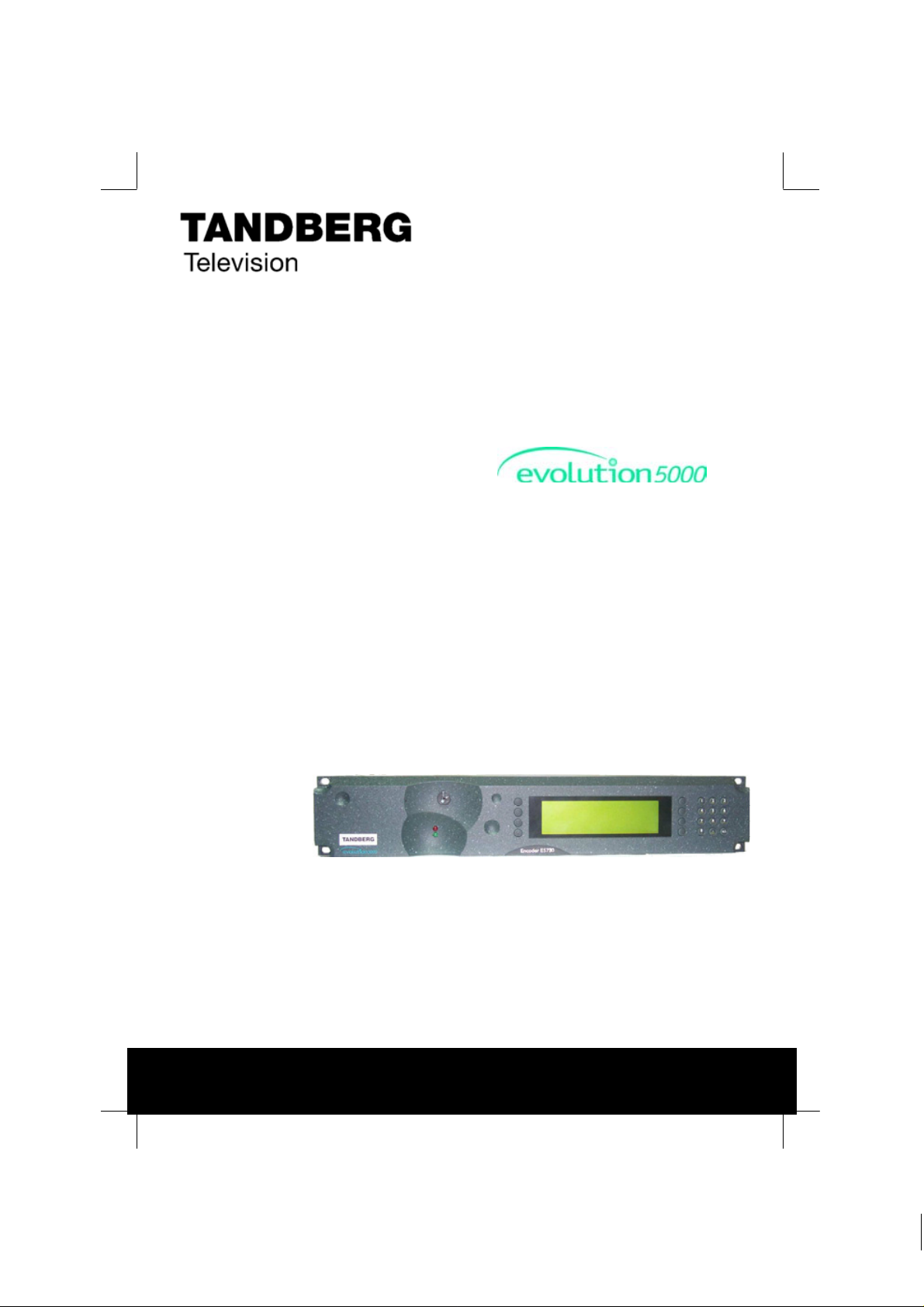
E5780 and E5782 Encoder
USER GUIDE
Build Version 3.6.0
(and later)
E5780/E5782 Encoder
ENGLISH (UK)
www.tandbergtv.com
Page 2

evolution 5000 E5780 and E5782 Encoder
Trademarks
Dolby® / Dolby® Digital / AC-3® are registered trademarks of Dolby
Laboratories Licensing Corporation.
Customer Services
Europe, Middle East Tel: +44 (0) 23 8048 4455
and Africa: Fax: +44 (0) 23 8048 4467
support@tandbergtv.com
Americas: Tel: +1 (321) 308 0470
fieldservice-americas@tandbergtv.com
China: Tel: +86 10 6856 0260 (Beijing)
Tel: +852 2530 3215 (Hong Kong)
fieldservice-asia@tandbergtv.com
Australia/NZ: Tel: +61 2 8923 0450
fieldservice-australia@tandbergtv.com
Internet Address: http://www.tandbergtv.com
Technical Training
International: Tel: +44 (0) 23 8048 4229
Fax: +44 (0) 23 8048 4467
training@tandbergtv.com
This document and the information contained in
it is the property of TANDBERG Television Ltd
and may be the subject of patents pending and
granted. It must not be used for commercial
purposes nor copied, disclosed, reproduced,
stored in a retrieval system or transmitted in
any form or by any means (electronic,
mechanical, photocopying, recording or
otherwise), whether in whole or in part, without
TANDBERG Television’s prior written agreement.
© 2003 - 2005 TANDBERG Television Ltd. All
rights reserved.
2
Issue 2 first published in 2005 by:
TANDBERG Television Ltd
Registered Address:
Unit 2 Strategic Park, Comines Way,
Hedge End, Southampton,
Hampshire,
SO30 4DA
United Kingdom
Registered Company Number 03695535
Page 3

evolution 5000 E5780 and E5782 Encoder
Contents
1 Who Should Use This User Guide? ..................................................5
1.1 What Equipment is Covered by This User Guide? .................................. 5
1.2 Hardware and Software Options......................................................... 6
2 Installing the Equipment................................................................ 7
2.1 Introduction.................................................................................... 7
2.2 Operating Voltage............................................................................ 8
2.3 Power Cable and Earthing ................................................................. 8
2.4 Power Supply Stand-by Switch........................................................... 9
2.5 Connecting Up the Basic Encoder ....................................................... 9
2.6 Connecting the Encoder to the Power Supply ..................................... 12
3 Operating the Equipment From the Front Panel............................13
3.1 Introduction.................................................................................. 13
3.2 Establishing Local Control................................................................ 13
3.3 Navigating the Menus..................................................................... 14
4 Typical Operation and Setting of Parameters ............................... 16
4.1 Select Syntax................................................................................ 17
4.2 Load Default Configuration/Restore Factory Defaults........................... 17
4.3 Set the Remote Control Options....................................................... 17
4.4 Set the Mux Options....................................................................... 18
4.5 Set the Video Options..................................................................... 18
4.6 Set the VBI Options........................................................................ 19
4.7 Set the Audio Options..................................................................... 21
4.8 Set the Data Options...................................................................... 22
4.9 Set the Output Options................................................................... 22
4.10 Configuring Option Cards ................................................................ 22
4.11 Configuring the Encoder for Minimum Delay....................................... 22
4.12 Configuring the Encoder for Minimum Bit-rate.................................... 23
5 Typical Configurations..................................................................24
5.1 Stand-alone ATSC Encoder (SD) ...................................................... 24
5.2 Stand-alone ATSC Encoder (HD) ...................................................... 25
5.3 Contribution Feed (4:2:2) (SD)........................................................ 26
5.4 Contribution Feed (4:2:2) (HD)........................................................ 27
3
Page 4

evolution 5000 E5780 and E5782 Encoder
List of Figures
Figure 2.1: Stand-by Switch ..................................................................... 9
Figure 2.2: Rear Panel Component Parts and Connectors ............................ 10
Figure 3.1: Input Monitor in SD............................................................... 13
Figure 3.2: Summary Screen.................................................................. 14
Figure 3.3: Keypad and Display Functions................................................. 14
Figure 3.4: Accessing Inscriptions on the Keypad....................................... 14
Figure 3.5: Functions Associated With Softkeys ......................................... 15
Figure 4.1: Menu Tree ........................................................................... 16
List of Tables
Table 1.1: Equipment Model Descriptions.................................................... 5
Table 1.2: Hardware Options .................................................................... 6
Table 1.3: Software Options ..................................................................... 6
Table 2.1: Types of Connector ................................................................ 11
Table 2.2: Fuse Type and Rating ............................................................. 12
4
Page 5
evolution 5000 E5780 and E5782 Encoder
1 Who Should Use This User Guide?
This User Guide is written for operators/users of the E5780/5782
Encoders to assist in installation and operation. It is not intended to be
a detailed source of information. This can be found in the Reference
Guide companion document which is issued on CD.
WARNING
Do not remove the covers of this equipment. Hazardous voltages are
present within this equipment and may be exposed if the covers are
removed. Only TANDBERG Television trained and approved service
engineers are permitted to service this equipment.
CAUTION
Unauthorised maintenance or the use of non-approved replacemen ts may
affect the equipment specification and invalidate any warranties.
1.1 What Equipment is Covered by This User Guide?
Table 1.1: Equipment Model Descriptions
Model Number Marketing Code Description
E5780 Encoder
E5782 Encoder
M2/ENC/E5780
M2/ENC/E5782
2U MPEG-2 Encoder with 4:2:0 video
encoding mode. Available with the
Reflex1 option.
2U MPEG-2 Encoder with 4:2:0/4:2:2
video encoding mode. Available with
the Reflex1 option.
See Table 1.2 and Table 1.3 for a list of hardware and software options
available with the Encoder. Detailed information is in the Reference
Guide.
1
Reflex is only available when software option M2/ESO2/HDVBR is purchased.
5
Page 6

evolution 5000 E5780 and E5782 Encoder
1.2 Hardware and Software Options
Table 1.2: Hardware Options
Marketing Code Description
Daughter Card Options
M2/EDCOM2/BISS BISS2 scrambling option - Mode 0, 1 and BISS-E
Hardware Options
M2/EOM2/AUDLIN2 Additional Audio + Linear PCM
M2/EOM2/REMUX Remux Option Module
M2/EOM2/ASI-OPT SMPTE 310 (SSI) and ASI Optical Outputs
M2/EOM2/SSI-US SMPTE 310 (SSI) Outputs
M2/EOM2/ATMS155MM
M2/EOM2/ATMS155SM STM-1 OC3 Monomode Physical Interface Module
M2/EOM2/ATMS34 PDH/E3 Module
M2/EOM2/ATMS45 PDH/DS3 Module
M2/EOM2/ATMS155E STM-1 Electrical Module
M2/EOM2/IP IP Output Card
M2/EOM2/G703 G.703 Output Card
M2/EOM2/GPI General Purpose Interface (GPI) Option Card
STM-1 OC3 Multimode Physical Interface Module
(SDH STM-1/SONET STS-3c Multimode Optical)
(SDH STM-1/SONET STS-3c Monomode Optical)
6
Table 1.3: Software Options
Marketing Code Description
SD Options
M2/ESO2/NR Noise Reduction - four levels of professional-grade
M2/ESO2/PU Performance Upgrade/Bit-rate <1.5 Mbit/s - enables
M2/ESO2/VBR Reflex and VBR - automatic variable bit-rate at a
2
BISS is implemented according to Tech 3290 March 2000 and BISS-E is implemented
according to Tech 3292 April 2001.
adaptive noise reduction.
advanced TANDBERG Television coding algorithms
that increase the efficiency by at least 0.75 Mbit/s
per channel. It also reduces the lower bit-rate limit
to 256 kbit/s.
fixed quality setting for optimum bandwidth usage
in stand-alone or Reflex statistical multiplexing
modes.
Page 7

evolution 5000 E5780 and E5782 Encoder
Marketing Code Description
M2/ESO2/422 MPEG-2 422P@ML - for professional editing quality
M2/ESO2/RAS RAS (Remote Authorisation System) - allows
M2/ESO2/ACON Auto Concatenation - aligns the Encoder to the
M2/ESO2/AC3 Dolby Digital (AC-3) - enables Dolby AC-3 stereo
M2/ESO2/DVB-MHP MHP Timing Events
M2/ESO2/DTS DTS Audio
M2/ESO2/525VBIDATA
M2/ESO2/SCTE-353
HD Options
M2/ESO2/HDNR HD Noise Reduction
M2/ESO2/HDVBR Reflex and VBR - automatic variable bit-rate at a
M2/ESO2/HD422 MPEG-2 422P@ML - for professional editing quality
pictures, 1.5 Mbit/s to 50 Mbit/s.
material to be protected from illegal viewing using
TANDBERG Television’s proprietary scrambling
system.
previous Encoder’s GOP structure to significantly
reduce coding artefacts caused by successive coding
and decoding.
encoding.
NABTS and GEMSTAR 2.0 VBI extraction
Splice Points Licence key
fixed quality setting for optimum bandwidth usage
in stand-alone or Reflex statistical multiplexing
modes.
pictures.
2 Installing the Equipment
2.1 Introduction
For best performance and reliability follow the instructions for site
requirements and installation in the Reference Guide and only use
installation accessories recommended by the manufacturers.
3
M2/ESO2/SCTE-35 only available when M2/EOM2/GPI purchasable option installed.
7
Page 8

evolution 5000 E5780 and E5782 Encoder
2.2 Operating Voltage
All Encoder models are fitted with a wide-ranging power supply. It is
suitable for supply voltages of 100-120 Vac -10% +6% or 220-240 Vac
-10% +6% at 50/60 Hz nominal.
CAUTION
This product should be operated only from the type of power source
indicated on the marking label. If you are not sure of the type of power
supply to your business, consult a qualified electrical engineer or y our
local power com p a n y .
NOTE
Refer to the Reference Guide for details of the colour codes used on
the mains leads.
See Table 2.2 for fuse information and also the Reference Guide for a
full power supply specification.
2.3 Power Cable and Earthing
8
Check that the power cable is suitable for the country in which the
Encoder is to be used.
WARNINGS
1. The Technical Earth is not a Protective earth for electric shock
protection.
2. This unit must be correctly earthed through the moulded plug
supplied. If the local mains supply does not have an earth
conductor do not connect the unit. Contact Customer Services
for advice.
3. Before connecting the unit to the supply, check the supply
requirements in Annex B of the Reference Guide.
Page 9

evolution 5000 E5780 and E5782 Encoder
2.4 Power Supply Stand-by Switch
This switch puts the Encoder into stand-by mode. It powers down the
supply rails of the display and internal circuits within the unit. The
switch type avoids accidental powering-down of the Encoder. For normal
use, using a screwdriver, ensure that the I is always at the top (see
Figure 2.1).
NOTES
1. This product should be operated only from the type of power
source indicated on the marking label.
2. If you are not sure of the type of power supply to your business,
consult a qualified electrical engineer or yo ur local power
company.
WARNING
This is NOT a mains switch and will not isolate the Encoder from the
power supply. Disconnect the power cord to isolate the unit.
On position
Stand-by position
Figure 2.1: Stand-by Switch
2.5 Connecting Up the Basic Encoder
Always use the specified cables supplied for signal integrity and
compliance with EMC requirements (see Annex B of the Reference
Guide).
Only those connectors used are labelled in Figure 2.2 and described in
Table 2.1.
9
Page 10

evolution 5000 E5780 and E5782 Encoder
Base
Board
Option
Slots 4-6
Option
Slots 1-3
RS-422 Data
Alarm
Option Slot 1
RS-232 Data
RS-232/ RS-485
Control
HD SDI
Input
Figure 2.2: Rear Panel Component Parts and Connectors
Ethernet
Option Slot 3
ASI
Outputs
SDI In
H Sync
Composite
Video
Option Slot 6
Option Slot 2
Audio In and
Audio Reference Out
Technical
Earth
10
Page 11

evolution 5000 E5780 and E5782 Encoder
Table 2.1: Types of Connector
Type of Connector Description
SDI IN
HD SDI INPUT
COMP VIDEO
H SYNC
Audio In
ASI OUT 1, 2 and 3
Ethernet #1 and #2 An 8-way, RJ-45 connector provides a 10BaseT Ethernet
RS-232/RS-485
Control
Alarm If required, connect an external status monitoring device
RS-232 RS-232 data is available on the Base Board and the
RS-422 A 15-way, D-type female connector provides an RS-422
Technical Earth Connect the Encoder's Technical earth to a suitable
A 75 Ω BNC connector provides a serial digital video input
to the unit. This input is terminated in 75 Ω.
A 75 Ω BNC conne ctor provi des an H D seri al di gital video
input to the unit. This input is terminated in 75 Ω.
A 75 Ω BNC connector provides a high quality analogue
video input to the unit.
Optional - Studio Black and Burst should be fed to the
75 Ω BNC connector (H SYNC). This genlocks the
Encoder to the Studio system. This method may be
required with some audio formats, or for locking
Encoders to an evolution 5000 Multiple x er.
The 15-way, D-type male connector is used in different
ways according to the audio input and the encoding
configuration selected.
The connector provides two stereo pairs which may be
independently configured as either analogue or digital.
The left channel is used to input digital audio.
The Encoder is supplied with a break-out cable which
plugs into this connector, and provides a more
convenient means of connecting the audio signals via
five connectors. There are four XLR female connectors,
with the fifth cable being a BNC which provides an
AES/EBU 75 Ω digital reference output. This is for when
the unit is connected to an external Dolby Digital
Encoder.
A 75 Ω BNC connector provides the output from the
Encoder. Connect the Multiplexer or Modulator ASI cable
to the appropriate ASI OUT connector, using good
quality 75 Ω coaxial cable (for example, BBC PSF 1/3).
interface for communications with the TDC/MEM for
control and monitoring. The Encoder has a single
switched Ethernet channel. Ethernet#1 is selected as
default at power-up. If a carrier is not detected on
Ethernet#1 then the input switches to Ethernet#2. This
gives a redundant Ethernet control via two hubs.
A 9-way, D-type male connector provides an
RS-232/RS-485 port for remote control of the Encoder.
This connector is wired as a DTE.
to the ALARM connector. A 9-way, D-type male
connector provides an alarm relay interface which can
be used to send a signal to remote equipment.
option module M2/EOM2/DAT.
synchronous, serial communications data input interface.
point.
11
Page 12

evolution 5000 E5780 and E5782 Encoder
NOTE
Refer to the Reference Guide for all power supply, fuse, safety, EMC
information and operating conditions.
2.6 Connecting the Encoder to the Power Supply
WARNINGS
1. Do not overload wall outlets and extension cords as this can
result in a risk of fire or electric shock
2. As no mains switch is fitted to this unit, ensure the local power
supply is switched OFF before connecting the supply cord.
3. The Encoder is not fitted with an on/off switch. Ensure that the
socket-outlet is installed near the equipment so that it is easily
accessible. Failure to isolate the equipment properly may cause
a safety hazard.
Connect the Encoder to the power supply as follows:
!Power Supply
Ensure the power supply is isolated and switched off.
12
!Encoder
Ensure the correct fuse type and rating has been fitted to both the
equipment and the power cable.
!Supply Cord
Connect the lead to the Encoder input connector and then to the
power supply. Switch on the power supply.
Table 2.2: Fuse Type and Rating
Power Supply Fuse Type and Rating
100-120 Vac / 220-240 Vac IEC/EN 60127-2 Sheet 5
Bussmann S505/Littelfuse 215
5 A 250 V T HBC
Page 13

evolution 5000 E5780 and E5782 Encoder
3 Operating the Equipment From the Front Panel
3.1 Introduction
The front panel display and keypad may be used to configure, control
and monitor the Encoder when an external control system is not used.
3.2 Establishing Local Control
3.2.1 Input Monitor / Keyboard Lock
At power-on the Encoder runs through a boot sequence (boot time
without any option modules is approximately 45 seconds). An initial
Input Monitor screen is shown. Figure 3.1 shows SD mode (HD not
available in build version 3.3).
Key icon, shown in the unlocked
position.
Figure 3.1: Input Monitor in SD
The softkeys can be locked out to prevent inadvertent operation (see
the key icon in Figure 3.1). Press the softkey adjacent to the key icon.
This shows the Keyboard Lock screen. Press the Yes softkey to disable
the softkeys. They are all disabled with the exception of Unlock.
To enable and restore the softkey functions, press the Unlock softkey.
This shows the Keyboard Lock screen. Press the Yes softkey.
13
Page 14

evolution 5000 E5780 and E5782 Encoder
play
pp
A
3.2.2 Summary Screen
On or Off Air.
Indicates whether or not the mux
On Air option is set to on or off.
Clear or Scrambled.
Indicates whether or not the output
is scrambled.
Figure 3.2: Summary Screen
3.3 Navigating the Menus
3.3.1 Moving Through the Menu Screens
This gives quick access to
the Configurations menu
Press More softkey to
access the Advanced (Top
Level) menu
Each softkey on each side of the
display is used to access, select
and sometimes amend the menu
item associated with it.
Figure 3.3: Keypad and Display Functions
3.3.2 How to Use the Keypad
Press the softkey once to have a
2 a
ear on the display screen
screen
Press the softkey twice in rapid
succession for an A to appear on the
dis
Figure 3.4: Accessing Inscriptions on the Keypad
14
Where there is a +/- sign
associated with a softkey,
this scrolls through a set
of options.
Press the softkey three times in rapid succession
to have a B appear on the display screen
2
Press the softkey four times in rapid succession
BC
to have a C appear on the display screen
This keypad is used to amend
the menu option which has been
selected (unless indicated
Page 15

evolution 5000 E5780 and E5782 Encoder
3.3.3 How to Use the Functions Associated with Softkeys
The following display screens show the different functions associated
with the options.
Press Left and Right
to move the
underscore to the
next letter that you
want to change.
Press Ins to insert a
space where the
underscore is.
Press Del to delete
where the
underscore is.
On Air / Off Air indicates
whether the mux On Air option
is set to on or off.
Softkeys mean those at the side of the
screen and those on the keypad.
Scramble means that
scrambling is enabled. Clear
means that it is not.
Figure 3.5: Functions Associated With Softkeys
NOTE
A black diagonal cross enclosed by a white circle ( ) means that
the Encoder is under remote control and the user does not have
access to change that parameter.
Press + and - to scroll
through the choices in
the option.
Press Enter to accept
the option choice.
Press Quit to revert to
previous menu.
15
Page 16

evolution 5000 E5780 and E5782 Encoder
A
V
4 Typical Operation and Setting of Parameters
Summary
Screen
Ops
Cfgs....
More....
Quit
Advanced
Menu
Setup....
Errors....
Diagnostics....
Ops
Configs....
Quit
Front Panel
Diagnostics
Menu
Config
Menu
Errors
Menu
Setup
Menu
System....
Video....
Audio....
Data....
Output....
Mux....
ATM....
Quit
System
Menu
Service Info....
Remote Control....
General....
Advanced....
Mbd Services ....
Build....
Quit
ideo
Menu
Video Source....
Video Encoder....
VBI....
udio
Menu
Audio A....
Audio B....
Audio XLR....
Audio Languages
Data
Menu
Data A - RS232....
Data B - RS422....
Data X A - RS232....
Data X B - RS422....
16
Figure 4.1: Menu Tree
Output
Menu
Output Format
Delivery Descriptor....
IP Streamer....
Mux
Menu
Mux....
Page 17

Refer the following steps for a typical set-up. See Figure 4.1 for the
menu tree and Section 4.1 onwards on how to navigate the menus. For
more detailed information or parameters not mentioned refer to the
Reference Guide.
!Select the syntax.
!Optional - load a default configuration and amend if necessary or
restore the factory defaults. Refer to Section 5 for examples of
typical configurations.
!Set the remote control options.
!Set the mux options.
!Set the video options.
!Set the audio options.
!Set the data options.
!Set the output options.
4.1 Select Syntax
Navigate to the Service Info Menu and select the Syntax option.
Choose DVB or ATSC, as required. The service information for the
service can then be set in the Service Info Menu.
evolution 5000 E5780 and E5782 Encoder
4.2 Load Default Configuration/Restore Factory Defaults
From the Summary screen navigate to the Configs Menu. Select Load
Active Config and choose one of the configurations. Amend the
parameters as necessary.
4.3 Set the Remote Control Options
If the Encoder is to be controlled via its Ethernet interface the unit's IP
address and associated parameters must be set in the Remote Control
Menu.
Alternatively, if the Encoder is to be controlled via RS-232/RS-485, the
serial protocol, baud-rate and unit address must be set in the Remote
Control Menu.
17
Page 18

evolution 5000 E5780 and E5782 Encoder
Navigate to the Remote Control Menu. Select the following options:
!IP Address Option – enter or change the IP address of the unit.
!Serial Protocol Option – select RS-485 or RS-232.
!Change other options as required.
4.4 Set the Mux Options
Navigate to the Mux Menu. Select the following options:
!Packet Length Option – select either 188 (typical) or 204 bytes.
!On Air – set to On to send the output of the Encoder to the
Multiplexer.
!Bit-rate (188) / Bit-rate (204) Options – select the required
bit-rate.
NOTE
If the Packet Length option is set to 188 bytes then only the
Bit-rate (188) option is displayed. If the Packet Length option is set
to 204 bytes then both the Bit-rate (188) and Bit-rate (204) options
are displayed.
4.5 Set the Video Options
Navigate to the Video Menu and select the Video Encoder Menu to
configure the video input to the Encoder. Select the following options:
!Profile\Level Option – select MP@ML, 422P@ML, MP@HL or
422P@HL.
NOTE
This option is always MP@ML or MP@HL and cannot be changed
unless the M2/ESO2/422 or M2/ESO2/HD422 software option is
enabled.
18
Page 19

evolution 5000 E5780 and E5782 Encoder
!Compression Mode – select the required compression mode.
Standard is the default mode. The various seamless modes allow
the bit-rate to be changed, over a defined range, without a break in
transmission. The low delay modes use various techniques to
reduce the encoding delay, but picture quality may reduce (see the
Reference Guide for more details).
NOTE
In SD changing compression mode can change the GOP structure
and length.
!Bit-rate – select the required video bit-rate. This defaults to the
maximum possible bit-rate given the current mux bit-rate set, and
the bit-rates set for the other elements such as audio and data.
NOTE
In SD, high bit-rates in low resolutions cannot always generate
sufficient bits to match the requested bit-rate. However, a valid
picture is still produced.
!Exit the Video Encoder Menu and then select the Video Source
Menu to configure the following option.
!Video Input – select the video input required. The video input
options depend upon the profile selected. If the selected input is SD
SDI, the frame rate must also be set. For HD formats choose the
correct input (see the Reference Guide for details).
4.6 Set the VBI Options
Navigate to the Video Menu and select the VBI Menu. The options
available depend on whether the video source is 625 lines, 25 Hz or
525 lines, 29.97 Hz.
VBI In Picture (SD only) - if the video profile level is 422P@ML, then a
VBI In Picture option is available. This transmits the VBI lines as part
of the picture. They will suffer some distortion, and so this is not
suitable for all VBI types, e.g. Video Index.
19
Page 20

evolution 5000 E5780 and E5782 Encoder
NOTES
1. Requires up to 3 Mbit/s of video bit-rate to carry this additional
information.
2. 3:2 pulldown cannot be used when using this option.
VBI Options (625 lines, 25 Hz) – in SD the Encoder can extract a
maximum of eight VBI lines per field on the SD inputs. However this
limit does not apply to Teletext. The possible VBI lines are 6 – 23 and
318 – 335.
In SD the possible VBI types are; Vertical Interval Time Code (VITC),
Video Index, Teletext System B, Inverted Teletext, Wide Screen
Signalling, and Video Programming System (VPS).
In HD Teletext can be extracted from the SD inputs and put into the
stream on its own PID.
!Teletext - to enable the processing of Teletext select the following
options:
Teletext All Lines – set to On to enable Teletext System B
extraction from all VBI lines.
Teletext PID – assign the PID to be used to carry the extracted
Teletext data.
VBI Line – select individual VBI lines to either turn Teletext
extraction off for that line, or to change the VBI type.
!Other VBI types (SD only) - to enable the processing of VBI other
than Teletext select the following options:
VBI on PID – set to On to enable the extracted VBI data to be
carried on a separate PID.
VBI PID - assign the PID to be used to carry the VBI data.
VPS (Line 16) – set to On if VPS is to be extracted from
line 16.
WSS (line 23) – set to the appropriate WSS type, if WSS is to
be extracted from line 23. The WSS types are ETSI 300 294, or
WSS-AFD.
Auto Detect VITC – set to On if the Encoder is required to
automatically detect the presence of VITC and extract it. In HD
the timecode is extracted according to SMPTE RP188 from the
HD SDI.
VBI Lines – if necessary, select individual VBI lines to set the
VBI type that the Encoder should extract from that line.
20
Page 21

evolution 5000 E5780 and E5782 Encoder
VBI Options (525 lines, 29.97 Hz) - in SD the Encoder can extract a
maximum of eight VBI lines per field. The possible VBI types are;
Vertical Interval Time Code (VITC), Video Index, Closed Caption,
Neilson AMOL 1, and Neilson AMOL 11.
To enable the processing of VBI select the following options:
!VBI on PID – set to On to enable the extracted VBI data to be
carried on a separate PID.
!VBI PID - assign the PID to be used to carry the VBI data.
!Auto Detect VITC – set to On if the Encoder is required to
automatically detect the presence of VITC and extract it. In HD the
timecode is extracted according to SMPTE RP188 from the HD SDI.
!VBI Lines – select individual VBI lines to set the VBI type that the
Encoder should extract from that line (SD only).
!Clo sed Captions – set to the required source of closed caption
data. The options are; video line 21, video line 21 and line 284,
SMPTE 333M, SCTE20, SCTE21 or SCTE20 & 21.
!CC Format – select the required closed caption format, the default
is ATSC, and this is the required setting for EIA-708B compliant
closed captions.
!SMPTE 333M Port – if the closed caption source has been set to
SMPTE 333M, then the Encoder’s RS-232 port through which the
data is to be input must be selected.
!SMPTE 334 CC can be extracted from the HD-SDI.
For more details regarding setting up the Encoder’s closed caption
options see the Reference Guide.
4.7 Set the Audio Options
The standard Encoder can process two stereo pairs, but up to four can
be processed with the addition of audio option cards. All the audio
inputs are configured in a similar manner.
Navigate to the Audio Menu. Select the following options:
!Source Option - select the audio source. This can be an analogue
or a digital input, or can be de-embedded from the SDI input. If the
audio source is embedded in the SDI (HD or SD) then the audio
DID must be set. Entering 1024 for the DID causes the default DID
for the selected group to be used.
!Coding Standard Option - Select the coding standard, e.g.
MPEG Layer 2, Dolby Digital (AC-3) etc.
!Bit-rate Option - select the required audio bit-rate.
21
Page 22

evolution 5000 E5780 and E5782 Encoder
4.8 Set the Data Options
Navigate to the Data Menu. If serial data, either RS-232 or RS-422, is to
be encoded then configure the input source and bit-rates.
4.9 Set the Output Options
The Output Menu allows the output of the Encoder to be selected. This
is set to ASI unless an option card providing an alternative output is
fitted. If the output is set to ASI, a Delivery Descriptor Menu is
available, which allows all the parameters in the delivery descriptor to
be set.
4.10 Configuring Option Cards
For information regarding configuring any option cards that may be
fitted to the Encoder please refer to the Reference Guide.
4.11 Configuring the Encoder for Minimum Delay
There is a trade-off between encoding delay and picture quality for a
given bit-rate. The parameters that can be adjusted to reduce the
encoding delay are as follows:
22
!Clock Source - the Clock option is found in the Mux Menu. Setting
the clock source to either HSYNC or Video, means that the frame
resynchroniser in the video input of the Encoder is not used, which
removes between 0 and 40 ms of delay.
!Compression Mode - the Compression Mode option is found in
the Video Encoder Menu. There are three compression modes in
SD that reduce coding delay; Low Delay, Very Low Delay, and Mega
Low Delay and one in HD mode: Low Delay.
Low Delay mode reduces the size of the video rate buffer, which
results in a smaller encoding delay. This can compromise video
quality in some circumstances.
Very Low Delay mode also reduces the size of the video rate buffer,
but it also forces the GOP structure to IP, which removes the frame
reordering delay, and uses field pictures.
Mega Low delay mode is not fully DVB compliant. It has a smaller
video rate buffer than Very Low Delay mode, it also uses a GOP
structure of IP and different refresh techniques.
Page 23

evolution 5000 E5780 and E5782 Encoder
!Video Bit-rate - the video bit-rate can be set in the Video
Encoder Menu. The simple rule is that the higher the bit-rate, the
lower the encoding delay.
4.12 Configuring the Encoder for Minimum Bit-rate
The following parameters can be configured to minimise the video
bit-rate required for a given picture quality:
!Compression Mode - the Compression Mode option is found in
the Video Encoder Menu. For minimum bit-rate this should be set
to standard.
!Video Bandwidth - the Video Bandwidth option is found in the
Video Source Menu. To minimise the video bit-rate this should be
set to medium, or better still soft. However, this does affect the
sharpness of the pictures.
!Noise Reduction - if the noise reduction option has been
purchased, then there will be a Noise Reduction option in the
Video Source Menu. The higher the level of noise reduction set,
the lower the video bit-rate, but the sharpness of the pictures will
be reduced.
Three new noise reduction levels have been added in SV 3.6.0.
Please refer to the Reference Guide.
!Video Resolution - the Resolution option is found in the Video
Encoder Menu. Selecting a lower resolution reduces the required
video bit-rate, but also reduces the amount of detail in the picture.
In HD certain vertical resolutions do not support different horizontal
resolutions.
!GOP Structure - the GOP Structure option is found in the Video
Encoder Menu.
A new option, “Adaptive GOP”, has been added in SV 3.6.0. Please
refer to the Reference Guide. This option has always been available
in HD mode.
!Long GOP - if the performance upgrade option has been
purchased, in the Video Encoder Menu there will be a Long GOP
which, if set to On, allows GOPs of greater than 0.5 seconds
duration to be selected. Setting a longer GOP may allow the video
bit-rate to be reduced, but at the cost of a longer time to acquire
the service. Also, if a very long GOP is used, the build-up of noise
up to the next I frame may become noticeable.
23
Page 24

evolution 5000 E5780 and E5782 Encoder
5 Typical Configurations
5.1 Stand-alone ATSC Encoder (SD)
To put the Encoder into a typical configuration for a stand-alone ATSC
Encoder perform the following:
!Navigate to the Config Menu.
!Load Active Config – select the ‘Standard (ATSC)’ configuration
which has the video bit-rate that is required.
A summary of the standard ATSC configuration is:
Syntax = ATSC
Mux bit-rate = 19.392658 Mbit/s
Video Source = NTSC with pedestal
Video Encoding Profile = MP@ML (4:2:0)
Compression Mode = Standard
Audio Channel A = Analogue Source, Dolby (AC-3) encoding at
384 kbit/s
Audio Channel B = Off
Closed captions = EIA-708B sourced from line 21 of the video.
!Navigate to the Service Info Menu and configure the SI
parameters such as channel name, and network name as required.
It may also be necessary to modify some of the other default settings to
suit the particular installation, see the Reference Guide for details.
24
Page 25

evolution 5000 E5780 and E5782 Encoder
5.2 Stand-alone ATSC Encoder (HD)
To put the Encoder into a typical configuration for a stand-alone ATSC
Encoder perform the following:
!Navigate to the Config Menu.
!Select HD Factory Defaults.
NOTE
Do this the first time that the menus are accessed. This is to ensure
that all SD and HD configurations are available for use.
!Load Active Config – select the ATSC configuration which has the
video resolution that is required.
A summary of the standard ATSC configuration is:
Syntax = ATSC
Mux bit-rate = 19.392658 Mbit/s
Video Source = HD-SDI
Video Encoding Profile = MP@HL
Compression Mode = Standard
Audio Channel A = Analogue Source, Dolby (AC-3) encoding at
384 kbit/s
Audio Channel B = Off
Closed captions = EIA-708B sourced from line 21 of SD SDI
input.
!Navigate to the Service Info Menu and configure the SI
parameters such as channel name, and network name as required.
It may also be necessary to modify some of the other default settings to
suit the particular installation, see the Reference Guide for details.
25
Page 26

evolution 5000 E5780 and E5782 Encoder
5.3 Contribution Feed (4:2:2) (SD)
Software option module M2/ESO2/422 is required for this installation.
To put the Encoder into a typical configuration for a contribution link
that requires 4:2:2 video carry out the following:
!Navigate to the Config Menu.
!Load Active Config – Select the ‘4:2:2’ configuration which has
the video bit-rate that is required. In 525 line selecting a DVB
configuration for a contribution feed is recommended.
A summary of the configuration is:
Mux bit-rate = 40 Mbit/s
Video Source = SDI (25 Hz or 29.97 Hz depending on line
standard)
Video Encoding Profile = 422P@ML (4:2:2)
Compression Mode = Standard
Video Bit-rate = 25 Mbit/s
Audio Channel A = Analogue Source, MPEG Layer 2 encoding at
384 kbit/s
Audio Channel B = Analogue Source, MPEG Layer 2 encoding at
384 kbit/s
It is probably desirable to modify the video bit-rate to that required, and
the mux bit-rate to the minimum required to carry the video and audio
channels defined.
26
It may also be necessary to modify some of the other default settings to
suit the particular installation (see the Reference Guide for details).
Page 27

evolution 5000 E5780 and E5782 Encoder
5.4 Contribution Feed (4:2:2) (HD)
The Encoder needs to be an E5782 for this mode. To put the Encoder
into a typical configuration for a contribution link that requires 4:2:2
video carry out the following:
!Navigate to the Config Menu.
!Select HD Factory Defaults.
NOTE
Do this the first time that the menus are accessed. This is to ensure
that all SD and HD configurations are available for use.
!Load Active Config – Select the 4:2:2 HD configuration which has
the video resolution that is required.
A summary of the configuration is:
Mux bit-rate = 40 Mbit/s
Video Source = HD SDI
Video Encoding Profile = 422P@HL (4:2:2)
Compression Mode = Standard
Video Bit-rate = 35 Mbit/s
Audio Channel A = Analogue Source, MPEG Layer 2 encoding at
384 kbit/s
Audio Channel B = Analogue Source, MPEG Layer 2 encoding at
384 kbit/s
It is probably desirable to modify the video bit-rate to that required, and
the mux bit-rate to the minimum required to carry the video and audio
channels defined.
It may also be necessary to modify some of the other default settings to
suit the particular installation (see the Reference Guide for details).
27
Page 28

evolution 5000 E5780 and E5782 Encoder
BLANK
28
 Loading...