

Page 1

ST.RE.E10076.3
Issue 3
ENGLISH (UK)
REFERENCE GUIDE
E5714/E5740-xxx DSNG,
E5750 DENG Voyager Encoder
Build Version 3.6.0 and later
1U Encoder
2U Encoder
Page 2

g
f
r
Preliminary Pages
ENGLISH (UK)
If you do not understand the contents of this manual
Also, translation into any EC official language of this manual can be made
READ THIS FIRST!
DO NOT OPERATE THIS EQUIPMENT.
available, at your cost.
En översättning till detta språk av denna handbok kan också anskaffas, på
Om Ni inte förstår informationen i denna handbok
ARBETA DÅ INTE MED DENNA UTRUSTNING.
SVENSKA
LÄS DETTA FÖRST!
Er bekostnad.
PORTUGUÊS
LEIA O TEXTO ABAIXO ANTES DE MAIS NADA!
O utilizador poderá também obter uma tradução do manual para o
Se não compreende o texto deste manual
NÃO UTILIZE O EQUIPAMENTO.
português à própria custa.
Si vous ne comprenez pas les instructions contenues dans ce manuel
En outre, nous pouvons vous proposer, à vos frais, une version française
AVANT TOUT, LISEZ CE QUI SUIT!
NE FAITES PAS FONCTIONNER CET APPAREIL.
FRANÇAIS
de ce manuel.
ITALIANO
LEGGERE QUESTO AVVISO PER PRIMO!
Se non si capisce il contenuto del presente manuale
NON UTILIZZARE L’APPARECCHIATURA.
È anche disponibile la versione italiana di questo manuale, ma il costo è a
LEES DIT EERST!
Als u de inhoud van deze handleiding niet begrijpt
STEL DEZE APPARATUUR DAN NIET IN WERKING.
U kunt tevens, op eigen kosten, een vertaling van deze handleiding
LUE ENNEN KÄYTTÖÄ!
Jos et ymmärrä käsikirjan sisältöä
ÄLÄ KÄYTÄ LAITETTA.
Käsikirja voidaan myös suomentaa asiakkaan kustannuksella.
LÆS DETTE FØRST!
MEDMINDRE DE TIL FULDE FORSTÅR INDHOLDET AF DENNE
Vi kan også for Deres regning levere en dansk oversættelse af denne
Udstyret må ikke betjenes
carico dell’utente.
NEDERLANDS
krijgen.
SUOMI
DANSK
HÅNDBOG.
håndbog.
Sollte Ihnen der Inhalf dieses Handbuches nicht klar verständlich sein,
Podemos asimismo suministrarle una traducción de este manual al
(idioma) previo pago de una cantidad adicional que deberá abonar usted
This document and the information contained in it is the property o
TANDBERG Television Ltd and may be the subject of patents
pending and granted. It must not be used for commercial purposes
nor copied, disclosed, reproduced, stored in a retrieval system o
transmitted in any form or by any means (electronic, mechanic al,
photocopying, recording or otherwise), whether in whole or in part,
without TANDBERG Television’s prior written agreement.
2004 - 2005 TANDBERG Television Ltd. All rights reserved.
LESEN SIE ZUERST DIESEN HINWEIS!
BEDIENEN SIE DIESE GERÄTE NICHT!
Eine Übersetzung des Handbuches in diese Sprache ist gegen
LEA ESTE AVISO PRIMERO!
Si no entiende el contenido de este manual
DEUTSCH
dann
Berechnung lieferbar.
ESPAÑOL
NO OPERE ESTE EQUIPO.
mismo.
ЕЛЛЗНЙКБ
ДЙБВБУФЕ РСЩФБ БХФП!
Бн ден кбфблЬвефе фп ресйечьменп бхфпэ фпх впзиЮмбфпт/егчейсйдЯпх
МЗН ЛЕЙФПХСГЗУЕФЕ БХФПН ФПН ЕОПРЛЙУМП.
ЕрЯузт, бхфь фп егчейсЯдйп еЯнбй дйбиЭуймп уе мефЬцсбуз
уе бхфЮ фз глюууб кбй мрпсеЯфе нб фп бгпсЬуефе.
Issue 3 first published in 2005 by:
ANDBERG TELEVISION LTD
T
R
EGISTERED ADDRESS:
NIT 2 STRATEGIC PARK,
U
OMINES WAY,
C
EDGE END, SOUTHAMPTON,
H
AMPSHIRE,
H
SO30 4DA
istered Company Number 03695535
Re
Page ii Reference Guide: E57xx DSNG and DENG Voyager Encoder
ST.RE.E10076.3
Page 3

List of Contents
Chapter 1: Introduction to the Basic Encoder
Gives a general description of the equipment and its main features and
functions. Identifies the controls, indicators and connectors on the front
and rear panels.
Chapter 2: Installing the Equipment
Provides a guide to the suitability of an installation and gives detailed
procedures for the preparation and installation of the equipment. Also
details the external connectors and provides important safety
information.
Chapter 3: Options and Upgrades
This chapter describes the options and upgrades available for the
E57xx series of Encoder models.
Chapter 4: Operating the Equipment Locally
Describes local control in detail. Provides the power-up/power-down
procedures and other general operating/control/set-up procedures.
Preliminary Pages
Chapter 5: Web Browser Interface
Details how to access and use the Web Browser Interface for a range of
diagnostic and other utilities.
Chapter 6: Preventive Maintenance and Fault-finding
Details routine maintenance tasks to be performed by the operator and
provides general servicing advice and fault-finding information. Provides
information regarding warranty and maintenance available from Customer
Services. Gives relevant disposal information.
Annex A: Glossary
Annex B: Technical Specification
Annex C: Language Abbreviations
Annex D: Creating and Downloading a Logo
Annex E: Band Plans
Annex F: Audio Modes
Annex G: Accuracy of Frequency Sources
Annex H: Use of Remux Card in ATSC
Annex I: EDH Capability for E57xx Encoders
Reference Guide: E57xx DSNG and DENG Voyager Encoder Page iii
ST.RE.E10076.3
Page 4

Preliminary Pages
About this Reference Guide
This Reference Guide provides instructions and information for the
installation, operation of the Encoder.
This Reference Guide should be kept in a safe place for reference for the
life of the equipment. It is not intended that this Reference Guide will be
amended by the issue of individual pages. Any revision will be by a
complete reissue. Further copies of this Reference Guide can be ordered
from the address shown on page viii. If passing the equipment to a third
party, also pass the relevant documentation.
Issues of this Reference Guide are listed below:
Issue Date Build Version Comments
1 June 2003 3.2 Initial release.
2 June 2004 3.5 and later
3 January 2005 3.6.0
NOTE…
The Build Version in the table refers to an overall number which encompasses all the various
software/firmware versions of video, audio, etc in the Encoder.
The following documents are also associated with this equipment:
Include functionality of SV 3.6.0. Delete obsolete options. Add
new Satmod, L-band and GPI cards.
• ST.US.E10076: User Guide
• ST.TS.SNMP.E10074: Simple Network Management Protocol
• ST.TS.E10074 Remote Control Protocol
• ST.AN.1094: Video Noise Reduction and Compression
• ST.AN.1110: Near Loss-less MPEG Concatenation
Without Helper Signals
• ST.AN.BW.E10074: Variable Bandwidth Feature of E57xx
Encoders
Nomenclature
The terms RS-232 and RS-422 have been superseded by EIA-232 and
EIA-422. However, because the original names are inscribed on the
Encoder the original terms are used in the text of this Reference Guide.
Page iv Reference Guide: E57xx DSNG and DENG Voyager Encoder
ST.RE.E10076.3
Page 5

Acknowledgements
General
All best endeavours have been made to acknowledge registered
trademarks and trademarks used throughout this Reference Guide. Any
notified omissions will be rectified in the next issue of this Reference
Guide. Some trademarks may be registered in some countries but not in
others.
Registered trademarks and trademarks used are acknowledged below and
marked with their respective symbols. However, they are not marked
within the text of this Reference Guide.
Registered Trademarks
AC-3®, Dolby Digital® and Pro Logic® are registered trademarks of Dolby
Laboratories Licensing Corporation.
Musicam
France (TDF), Europe, and is a registered trademark of CCS (now Musicam
USA Incorporated), USA.
Ethernet
XILINX
®
is a registered trademark of Thomson and Télédiffusion de
®
is a registered trademark of Xerox Corporation.
®
is a registered trademark of Xilinx Inc.
Preliminary Pages
Trademarks
Pozidriv™ is a trademark of European Industrial Services.
Reflex™ is a trademark of TANDBERG Television.
Windows NT™ is a trademark of Microsoft Corporation.
STREAMS™ is a trademark of TANDBERG Television.
NDS™ is a trademark of NDS Limited.
Reference Guide: E57xx DSNG and DENG Voyager Encoder Page v
ST.RE.E10076.3
Page 6

Preliminary Pages
Warnings, Cautions and Notes
Heed Warnings
All warnings on the product and in the operating instructions should be
adhered to. The manufacturer can not be held responsible for injuries or
damage where warnings and cautions have been ignored or taken lightly.
Read Instructions
All the safety and operating instructions should be read before this product
is operated.
Follow Instructions
All operating and use instructions should be followed.
Retain Instructions
The safety and operating instructions should be retained for future
reference.
WARNINGS GIVE INFORMATION WHICH, IF STRICTLY OBSERVED, WILL PREVENT PERSONAL
INJURY OR DEATH, OR DAMAGE TO PERSONAL PROPERTY OR THE ENVIRONMENT. THEY
ARE BOXED AND SHADED FOR EMPHASIS, AS IN THIS EXAMPLE, AND ARE PLACED
IMMEDIATELY PRECEDING THE POINT AT WHICH THE READER REQUIRES THEM.
Cautions give information which, if strictly followed, will prevent damage to equipment or other goods.
They are boxed for emphasis, as in this example, and are placed immediately preceding the point at
NOTES...
Notes provide supplementary information. They are highlighted for emphasis, as in this example, and
are placed immediately after the relevant text.
EMC Compliance
This equipment is certified to the EMC requirements detailed in Annex B,
Technical Specification. To maintain this certification, only use the leads
supplied or if in doubt contact Customer Services.
WARNINGS...
CAUTIONS...
which the reader requires them.
Page vi Reference Guide: E57xx DSNG and DENG Voyager Encoder
ST.RE.E10076.3
Page 7

Contact Information
TANDBERG Television Customer Services
Support Services
Our primary objective is to provide first class customer care that is tailored
to your specific business and operational requirements. All levels are
supported by one or more service performance reviews to ensure the
perfect partnership between TANDBERG Television and your business.
Warranty
All TANDBERG Products and Systems are designed and built to the highest
standards and are covered under a comprehensive 12 month warranty.
Levels of Continuing TANDBERG Television Service Support
For stand-alone equipment, then TANDBERG Television BASIC
Advantage is the value for money choice for you. BASIC provides you
with year-by-year Service long after the warranty has expired.
Preliminary Pages
For systems support you can choose either Gold or Silver Advantage.
These packages are designed to save you costs and protect your income
through enlisting the help of TANDBERG Television support specialists.
VOYAGER Advantage is the truly mobile service solution. This provides a
package specifically designed to keep you mobile and operational.
Call TANDBERG Sales for more details.
Where to Find Us
Europe, Middle East +44 (0) 23 8048 4455
and Africa: Fax: +44 (0) 23 8048 4467
support@tandbergtv.com
Americas: +1 (321) 308 0470
fieldservice-americas@tandbergtv.com
China: +86 10 6856 0260 (Beijing)
+852 2530 3215 (Hong Kong)
fieldservice-asia@tandbergtv.com
Australia/NZ: +612 8923 0450
fieldservice-australia@tandbergtv.com
Internet Address: http://www.tandbergtv.com
Reference Guide: E57xx DSNG and DENG Voyager Encoder Page vii
ST.RE.E10076.3
Page 8

Preliminary Pages
Technical Training
Training Courses
TANDBERG Television provides a wide range of training courses on the
operation and maintenance of our products and on their supporting
technologies. TANDBERG can provide both regularly scheduled courses and
training tailored to individual needs. Courses can be run either at your
premises or at one of our dedicated training facilities.
Where to Find Us
For further information on TANDBERG Television's training programme
please contact us:
International Telephone: +44 23 8048 4229
International Facsimile +44 23 8048 4467
E-mail Address: training@tandbergtv.com
Internet Address http://www.tandbergtv.com
Customer Services and Technical Training Postal Address
Tandberg Television
Unit 2
Strategic Park
Comines Way
Hedge End
Southampton
Hampshire
SO30 4DA
United Kingdom
Return of Equipment
If you need to return equipment for repair, please contact the Customer
Services Helpdesk on +44 (0) 23 8048 4455. A Returns Authorisation
Number (RAN) will be issued and full details of the unit will be logged.
Please ensure the RAN number is clearly marked on the packaging of the
unit. The unit should then be sent to the following address:
Tandberg Television – Customer Services
Unit 1
Strategic Park
Comines Way
Hedge End
Southampton
Hampshire
SO30 4DA
United Kingdom
Technical Publications
If you need to contact TANDBERG Television Technical Publications
regarding this publication, e-mail: techpubs@tandbergtv.com.
Page viii Reference Guide: E57xx DSNG and DENG Voyager Encoder
ST.RE.E10076.3
Page 9

1. Introduction to the Basic Encoder
Contents
1.1 Scope of this Reference Guide.................................1-3
1.1.1 Who Should Use This Reference Guide.......1-3
1.1.2 Build Version ................................................1-3
1.1.3 What Equipment is Covered by This
Reference Guide..........................................1-3
Equipment Models........................................1-3
1.2 Role of the Encoder in a System...............................1-4
1.2.1 Typical System.............................................1-4
1.2.2 DSNG Systems ............................................1-5
Overview.......................................................1-5
E5714...........................................................1-6
E5740/E5760................................................1-6
1.2.3 DENG Systems ............................................1-6
1.3 Summary of Features............................................... 1-7
1.3.1 Video Encoding ............................................1-7
MPEG-2 Encoding........................................1-7
Video Encoding Modes.................................1-7
Video Inputs..................................................1-7
Video Input Types.........................................1-7
Serial Digital Video Input Error Detection
and Handling (EDH) .....................................1-7
Video Encoding Functions............................1-7
Motion Estimation.........................................1-8
Variable Video Bit-rate..................................1-8
Coding Resolutions ......................................1-8
Internal Frame Synchroniser........................1-8
Output on Video Loss...................................1-9
1.3.2 Audio Encoding ............................................1-9
General.........................................................1-9
Audio Inputs..................................................1-9
Audio Channels..........................................1-10
Output on Digital Audio Loss......................1-10
Chapter 1
MPEG Encoding Modes..............................1-10
Dolby Digital (AC-3) Encoding Modes.........1-10
Test Tones..................................................1-10
Audio Variable Bit-rate................................1-10
Dolby Digital (AC-3)....................................1-11
1.3.3 Vertical Blanking Interval (VBI) Line
Processing Modes.......................................1-11
Introduction.................................................1-11
VBI in Picture..............................................1-11
VBI User Data.............................................1-11
VBI in PID ...................................................1-11
Teletext Extraction......................................1-12
1.3.4 Data Channels............................................1-12
1.3.5 Outputs .......................................................1-12
1.3.6 IF Modulation..............................................1-13
E5714..........................................................1-13
E5740..........................................................1-13
E5750..........................................................1-13
1.3.7 Control and Monitoring................................1-13
1.3.8 Options and Upgrades................................1-13
1.4 Guided Tour............................................................1-14
1.4.1 Enclosure....................................................1-14
1.4.2 Front Panel Description ..............................1-14
Front Panel Display, Navigation Keys,
Softkeys, Keyboard.....................................1-14
Power Supply Stand-by Switch...................1-14
1.4.3 Rear Panel Description...............................1-15
Introduction.................................................1-15
1.4.4 Boards in the Basic Encoder.......................1-16
Reference Guide: E57xx DSNG and DENG Voyager Encoder Page 1-1
ST.RE.E10076.3
Page 10

Introduction to the Basic Encoder
List of Figures
Figure 1.1: 1U Encoder Front View............................................... 1-4
Figure 1.2: 2U Encoder Front View............................................... 1-4
Figure 1.3: Typical DSNG Encoder Configuration......................... 1-5
Figure 1.4: Typical DENG System Configuration..........................1-6
Figure 1.5: 1U Encoder Front Panel Indicators........................... 1-14
Figure 1.6: Stand-by Switch........................................................ 1-15
Figure 1.7: 2U Encoder Front Panel Indicators........................... 1-15
Figure 1.8: E5750 (2U) Rear Panel Component Parts and
Connectors.................................................................1-15
List of Tables
Table 1.1: Build Version ................................................................1-3
Table 1.2: Equipment Model Descriptions.....................................1-4
Table 1.3: Video Bit-rate Range ................................................... 1-8
Table 1.4: Front Panel Indicators ................................................1-14
Table 1.5: Boards in the Basic Encoder...................................... 1-16
Page 1-2 Reference Guide: E57xx DSNG and DENG Voyager Encoder
ST.RE.E10076.3
Page 11

Introduction to the Basic Encoder
1.1 Scope of this Reference Guide
1.1.1 Who Should Use This Reference Guide
This Reference Guide is written for operators/users of the 1U and 2U
Voyager Encoders to assist in the installation, operation and day-to-day
care. These Encoders are referred to throughout this Reference Guide as
‘Encoder(s)’ unless there is a specific difference, where they will be
referred to by the model number.
WARNING…
DO NOT REMOVE THE COVERS OF THIS EQUIPMENT. HAZARDOUS VOLTAGES ARE PRESENT
WITHIN THIS EQUIPMENT AND MAY BE EXPOSED IF THE COVERS ARE REMOVED. ONLY
TANDBERG TELEVISION TRAINED AND APPROVED SERVICE ENGINEERS ARE PERMITTED TO
SERVICE THIS EQUIPMENT.
CAUTION…
Unauthorised maintenance or the use of non-approved replacements may affect the equipment
specification and invalidate any warranties.
This Reference Guide does not include any maintenance information or
procedures which would require the removal of covers.
1.1.2 Build Version
This Reference Guide has been written to cover the functionality in
Table 1.1.
Table 1.1: Build Version
E5714, E5740, E5750
Build Version 3.6.0 and later
The Build version indicates the status of the Encoder and refers to an
overall number which encompasses all the various software/firmware
versions of video, audio, etc. in the Base Board.
The current Build version can be found in the Build Menu (see Chapter 4,
Operating the Equipment Locally, Figure 4.9).
This number should be
quoted in all correspondence with TANDBERG Television.
1.1.3 What Equipment is Covered by This Reference Guide
Equipment Models
Each model of Encoder comprises an enclosure with a Base Board and
Modulator fitted as standard. The E5714 and E5740 are fitted with a
Satellite Modulator; the E5750 is fitted with an OFDM Modulator.
There are vacant slots for option modules; one in the E5714; three in the
E5760; four in the E5740; five in the E5750. These slots can be occupied
by any combinations of modules shown in Chapter 3, Options and
Upgrades.
Reference Guide: E57xx DSNG and DENG Voyager Encoder Page 1-3
ST.RE.E10076.3
Page 12

Introduction to the Basic Encoder
Figure 1.1: 1U Encoder Front View
Figure 1.2: 2U Encoder Front View
Table 1.2: Equipment Model Descriptions
Model
Number
E5714 Encoder M2/VOY/E5714 1U MPEG-2 DSNG Encoder with QPSK modulator. Has
E5740 Encoder M2/VOY/E5740 2U MPEG-2 DSNG Encoder with IF output satellite
E5740 Encoder M2/VOY/E5740-
E5750 Encoder M2/VOY/E5750 2U MPEG-2 DENG Encoder with OFDM modulator. Has
Marketing
Code
LBAND
Description
1
4:2:0/4:2:2
estimation.
modulator. Has 4:2:0/4:2:2
exhaustive motion estimation.
2U MPEG-2 DSNG Encoder with L-band output Satellite
Modulator. Has 4:2:0/4:2:2
exhaustive motion estimation.
4:2:0/4:2:2
estimation.
video encoding mode and fully exhaustive motion
1
video encoding mode and fully
1
video encoding mode and fully
1
video encoding mode and fully exhaustive motion
1.2 Role of the Encoder in a System
1.2.1 Typical System
The Encoder is a transportable digital exciter designed specifically for
mobile contribution applications. It is compact and lightweight, fully
MPEG-2 and DVB or ATSC compliant and has high performance for the
transmission of studio-quality video material. The equipment is designed to
be suitable for both flyaway use (within an appropriate flight case) and
truck installation.
The E5714 and E5740 contain the same high performance Encoder. The
E5714 is a 1U chassis housing the Encoder and a QPSK Satellite Modulator.
The E5740 is a 2U chassis housing the Encoder, and a Satellite Modulator
2
capable of QPSK, 8PSK
1
4:2:2 is only available when software option M2/ESO2/422 is purchased.
2
8PSK is only available when software option M2/ESO2/SM38PSK is purchased.
3
16QAM is only available when software option M2/ESO2/SM316QAM is purchased.
Page 1-4 Reference Guide: E57xx DSNG and DENG Voyager Encoder
ST.RE.E10076.3
and 16QAM3 modulation.
Page 13
Introduction to the Basic Encoder
r
Y
A
The Encoder has one card, containing a single video encoder, two stereo
4
audio encoders (dual standard MPEG-1 (layer 2)/Dolby Digital (AC-3)
5
composite video decoder, CA
, data input and general purpose VBI
),
extraction and encoding circuitry. It also contains either a satellite
modulator or an OFDM modulator.
High quality 4:2:0 or 4:2:2
digital noise reduction techniques
6
video encoding is ensured by the inclusion of
7
and many other proprietary algorithms
as well as standard MPEG compression techniques. Fully Exhaustive motion
estimation is also used.
Video can be input to the unit in serial digital component (SDI) format or
composite analogue (PAL/NTSC). There is also a logo overlay facility
allowing broadcasters to trademark material.
The audio functionality supports multiple sampling frequencies, bit-rates
and coding modes. Audio can be input in balanced analogue, digital
AES/EBU input as a discrete channel or embedded on serial digital video.
Various coding standards are supported, including Linear PCM. Additional
audio channels can be accommodated by purchasing the option module
M2/EOM2/AUDLIN2.
Unit functionality can be further extended with option modules (see
Chapter 3, Options and Upgrades).
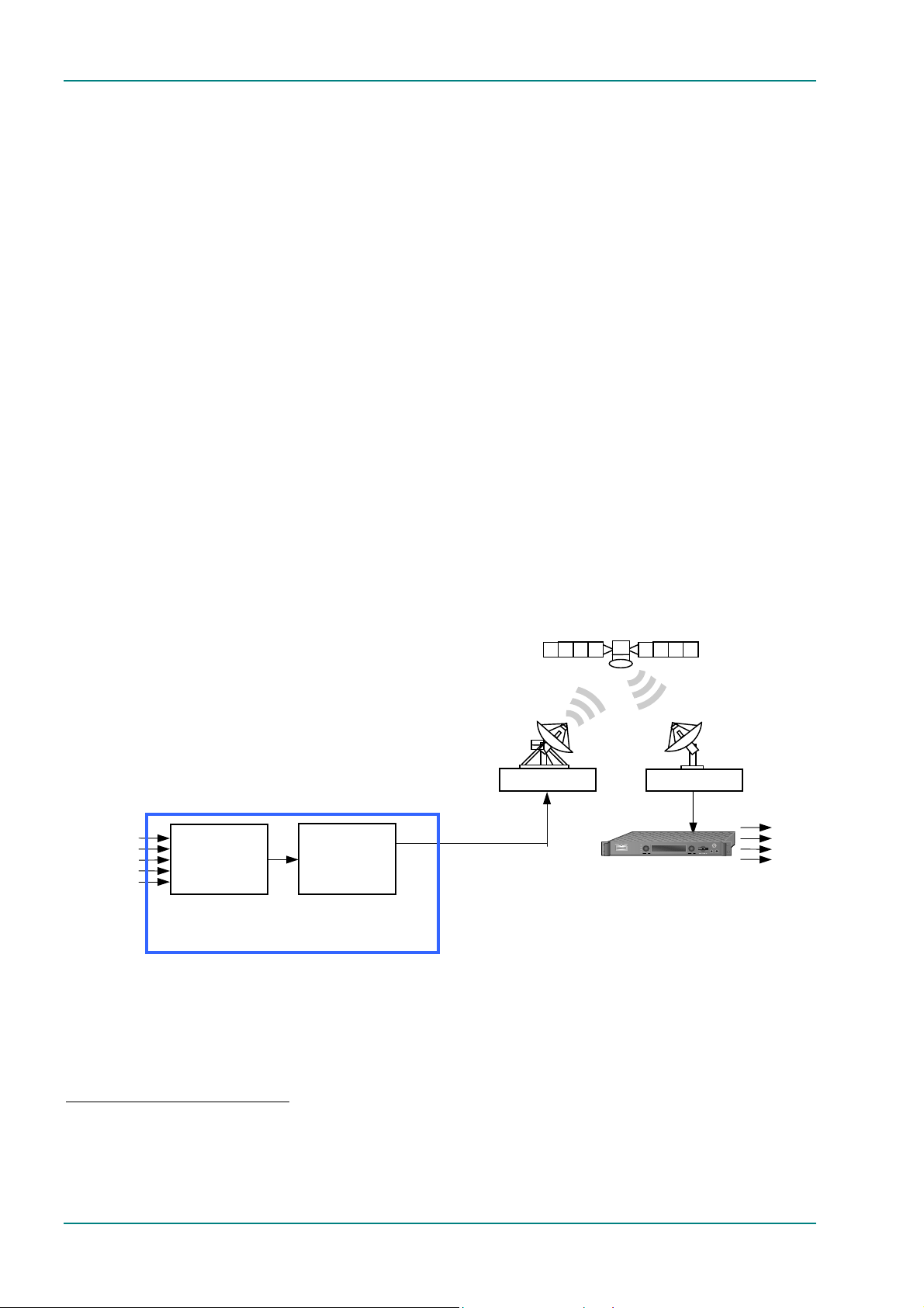
1.2.2 DSNG Systems
VIDEO (ANALOGUE)
VIDEO (DIGITAL)
AUDIO
SYNC DATA
ASYNC DATA
Overview
Encoder
Modulator
DSNG Encoder
Up-link equipment
(including Up-converte
and High Power Amplifier)
IF
Tx
ALARM
REMOTE CNTRL
AUTHORIZED
LOCK
BER STATUS
MULTIFUNCTIONAL DISPLA
STATUS
Satellite Receiver
Down-link equipment
(including Low Noise Block
and Down-converter)
Rx
ALTEI
VIDEO
AUDIO
ASYNC DATA
SYNC DATA
Figure 1.3: Typical DSNG Encoder Configuration
4
Dolby Digital (AC-3) is only available when software option M2/ESO2/AC3 is purchased.
5
CA relates to RAS and BISS. RAS and BISS are only available when software options M2/ESO2/RAS and
M2/EDCOM2/BISS are purchased. A E57xx Encoder may be fitted with both RAS and BISS options but only one
scrambling format can be used at any one time. BISS is available from Build version 2.1.0 but BISS- is not supported
before Build version 2.2.0.
6
4:2:2 is only available when software option M2/ESO2/422 is purchased.
7
Noise reduction is only available when software option M2/ESO2/NR is purchased.
Reference Guide: E57xx DSNG and DENG Voyager Encoder Page 1-5
ST.RE.E10076.3
Page 14
Introduction to the Basic Encoder
E5714
The satellite modulator within the E5714 supports QPSK modulation in
accordance with EN 300 421 (DVB-S). It provides a main and monitoring
IF Output. The IF frequency can be tuned between 50 MHz and 90 MHz, or
950 – 1750 MHz on the E5714 L-band.
E5740/E5760
The satellite modulator fitted within the E5740 is capable of QPSK
modulation in accordance with EN 300 421 (DVB-S), and is also capable of
8PSK and 16QAM modulation in accordance with EN 301 210 (DVB-DSNG).
It is available in two variants. One provides an IF output tuneable in the
range 50 MHz to 180 MHz. The other provides an L-band output tuneable
in the range 950 MHz to 1750 MHz.
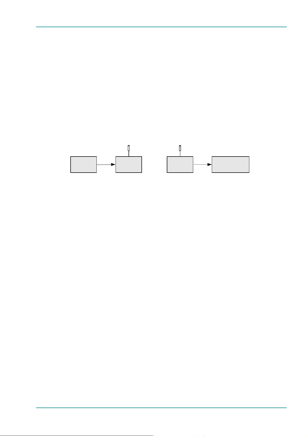
1.2.3 DENG Systems
70 MHz IF
E5715/E5750
Encoder
Radio Tx Radio Rx
Rec / Mon
Equipment
Figure 1.4: Typical DENG System Configuration
The OFDM modulator fitted in the E5750 takes the Encoder’s output
transport stream, and uses Coded Orthogonal Frequency Division
Multiplexing (COFDM) to spread the data over 1705 carriers (2k mode) or
6817 carriers (8k mode). This means that relatively low data rates can be
used on each carrier frequency, and any multipath effects (ghosting) which
occur affects only a small amount of data.
The carriers are closely spaced so that their sidebands overlap, but due to
the orthogonal relationship between carrier frequencies they do not
interfere with each other. This makes the system spectrally efficient.
Noise, multipath effects, co-channel interference and other impairments
can cause some bits to be received in error. Therefore, Forward Error
Correction (FEC) consisting of Reed-Solomon (RS) coding followed by
convolution coding is used to add extra bits to the transmitted signal. This
allows a large number of errors at the receive end to be corrected by
convolutional (Viterbi) decoding followed by RS decoding.
2
Five convolutional rates are available: ½,
/3, ¾, 5/6 and 7/8. These provide
different compromises between bit-rate and ruggedness.
The modulation scheme used on each carrier can either be QPSK, 16QAM,
or 64QAM. These also provide different compromises between bit-rate and
ruggedness, QPSK being the most rugged.
Four guard intervals are available
1
/32, 1/16, 1/8, and ¼. These are used to
reduce the effects of intersymbol interference at the receive end caused by
multipath propagation.
The output of the modulator is 70 MHz IF for connection to a suitable radio
transmitter.
Page 1-6 Reference Guide: E57xx DSNG and DENG Voyager Encoder
ST.RE.E10076.3
Page 15

1.3 Summary of Features
1.3.1 Video Encoding
MPEG-2 Encoding
The Encoder processes a broadcast-standard video signal into a
compressed encoded bit-stream in accordance with:
• The MPEG-2 Main profile @ Main level (MP@ML) specification
(ISO/IEC 13818)
• The MPEG-2 4:2:2
(ISO/IEC 13818)
Video Encoding Modes
Either the 4:2:0 or 4:2:28 video encoding modes can be selected. The
coding mode selected affects the compression techniques, encoder delay
and rate control.
Video Inputs
8
profile @ Main Level (422P@ML) specification
Introduction to the Basic Encoder
The standard video inputs are:
• SDI - Serial Digital Interface - ITU-R BT.656-4, part 3 (D1 serial
format) – SMPTE 259 (component only)
• Composite Analogue (PAL/NTSC)
Video Input Types
The video input types which are supported are:
• 625-line composite PAL-B, -D, -G, -H or -I (ITU-R BT. 624-4)
• 525-line composite NTSC-M (with and without pedestal) or PAL-M
(ITU-R BT. 624-4)
• Serial digital (ITU-R BT.656-4, part 3) input (D1 serial format) and
(ANSI/SMPTE 259M) (component only)
• Internal test pattern function
Serial Digital Video Input Error Detection and Handling (EDH)
The serial digital video input supports error detection and handling (EDH)9
as defined by the specification SMPTE RP 165-1994, ‘Error Detection
Checkwords and Status Flags for Use in Bit Serial Digital Interfaces for
Television’.
Video Encoding Functions
The standard video encoding functions include:
• Support for all MP@ML and 422P@ML
• Selectable bit-rate operation, <1.5 Mbit/s - 50 Mbit/s (see Table 1.3)
8
standard coding modes
10
• Support for the standard set of video picture resolutions (720, 704,
640, 544, 480, 352) in both 625 and 525 line operation. 352 supports
full and half-vertical resolution in both 625 and 525 line operation
8
4:2:2 is only available when software option M2/ESO2/422 is purchased.
9
Error detection and handling is not currently supported.
10
Bit-rates lower than 1.5 Mbit/s are only available when the software option M2/ESO2/PU is purchased.
Reference Guide: E57xx DSNG and DENG Voyager Encoder Page 1-7
ST.RE.E10076.3
Page 16

Introduction to the Basic Encoder
• Fully exhaustive motion estimation
• An internal frame synchroniser (see Internal Frame Synchroniser on
Page 1-8)
• Support for Active Format Descriptor (AFD) (see Chapter 4, Operating
the Equipment Locally, Table 4.36)
• Support for a variety of Group of Pictures (GOP) structures with a
variable number of B frames
• Built-in patented adaptive noise reduction circuitry
• A logo overlay facility whereby the Encoder is able to overlay
broadcasters trademarks/logos onto the active video
Motion Estimation
Fully Exhaustive motion estimation is used. It takes a macro block of
16 pixels x 16 pixels and then performs an exhaustive search without
subsampling.
Variable Video Bit-rate
The MPEG-2 compression algorithm uses adaptive field/frame coding,
forward and backward predictive processing with motion estimation and
compensation to reduce the bit-rate to the range shown in Table 1.3.
11
Table 1.3: Video Bit-rate Range
Video Encoding Mode
4:2:0 4:2:213
1.5 Mbit/s - 15 Mbit/s 1.5 Mbit/s - 50 Mbit/s
NOTE…
Minimum bit-rate is 0.25 Mbit/s when software option M2/ESO2/PU is purchased.
12
Coding Resolutions
To provide optimum picture quality over the full range of supported
bit-rates, the encoded picture resolution is controlled automatically
according to the video bit-rate. Alternatively, the user can override this
and select manual control, if desired. Coding resolutions are shown in
Annex B, Technical Specification.
Internal Frame Synchroniser
An internal frame synchroniser is provided to accommodate slight
differences between the incoming frame rate and that generated by the
stable reference
14
used by the Encoder.
11
Noise reduction is only available when software option M2/ESO2/NR is purchased.
12
The video bit-rate depends on the Multiplexer bit-rate which is set.
13
4:2:2 is only available when software option M2/ESO2/422 is purchased.
14
To ensure broadcast quality it is recommended that the studio reference is fed to HYSNC.
Page 1-8 Reference Guide: E57xx DSNG and DENG Voyager Encoder
ST.RE.E10076.3
Page 17

Output on Video Loss
The Encoder can be software-configured to show, in the event of video
input loss, either:
• A test pattern (with or without ident text)
• A freeze frame (with or without ident text)
• Cut to a black screen (with or without ident text)
• Drop the video PID
• Turn off the ASI output of the Encoder
1.3.2 Audio Encoding
General
Audio can be encoded to:
• MPEG-1 Audio (layer 2) standard (sampling rate 32 kHz or 48 kHz).
• Dolby Digital (AC-3)
Output bit-rate is selectable in the range 32 kbit/s - 384 kbit/s
(dependent on configuration) for MPEG-1 Audio (layer 2) and
56 kbit/s - 640 kbit/s (dependent on configuration) for Dolby Digital
(AC-3) coding mode selectable between 1/0 and 2/0.
15
Introduction to the Basic Encoder
(sampling rate 32 kHz or 48 kHz)16.
• Dolby Digital (AC-3) pre-encoded audio (IEC 61937 specification) in
pass-through mode is also available (it only operates at 48 kHz). This
is where an audio stream has already been encoded externally, prior to
entering the Encoder.
• Linear PCM
• Dolby E Pass-thru
• DTS Pass-thru
NOTES…
1. See Annex F, Audio Modes for details of setting up the audio.
2. MPEG-1 audio sampling rate is fixed at 48 kHz when controlled from the front panel.
16
(SMPTE 302M).
16
16
.
Audio Inputs
The standard audio input is:
• AUDIO IN – 15-way male D-type - software selectable balanced
analogue or digital AES/EBU, with AES/EBU on left only. A break-out
cable is supplied which plugs into this connector and provides a more
convenient means of connecting the audio inputs via five connectors.
There are four XLR female connectors, with the fifth cable being a BNC
which provides an AES/EBU 75 Ω digital reference output.
• Alternatively, audio can be input embedded as AES/EBU on the serial
digital interface (SDI). In this mode a maximum of four stereo pairs
can be extracted from any two Data Identifiers (DIDs). Audio may be
converted to either of the standard output sampling frequencies,
32 kHz or 48 kHz, by use of the built-in asynchronous sample rate
converters. This applies only to audio which is not pre-encoded.
15
Dolby Digital (AC-3) is only available when software option M2/ESO2/AC3 is purchased.
16
To achieve lip sync in all modes the audio option M2/EOM2/AUDLIN2 must be used.
Reference Guide: E57xx DSNG and DENG Voyager Encoder Page 1-9
ST.RE.E10076.3
Page 18

Introduction to the Basic Encoder
Audio Channels
The Encoder Base Board is capable of processing two stereo pairs, from
any of the following
17
:
• SDI Embedded source
• Digital source AES/EBU
• Analogue source, termination impedance 600 Ω or 20 kΩ
These signals may be processed using the encoding modes in the following
section.
Output on Digital Audio Loss
The Encoder can be software-configured, in the event of loss of digital
audio input lock loss, to either:
• Code an audio stream of silence
• Drop the audio PID
• Turn off the ASI output of the Encoder
MPEG Encoding Modes
The two stereo pairs may be configured in various encoding modes:
• Single mono: either the left or the right channel is encoded - the
signal is output to both XLR connectors at the receiving end. Not
available in Linear PCM.
• Dual mono: the left and right signals are encoded and carried in the
transport stream as a single Packetised Elementary Stream (PES) data
stream. The way that the left and right signals are output from the
Receiver is dependent on how the routing is set up on the Receiver.
Both the left and the right may be output, or the left only, or the right
only. This is typically used for multilingual services. Available in
MPEG-1 (layer 2) and Linear PCM.
• Stereo: A stereo pair is coded as two mono signals - the two signals
are output as stereo at the receiving end.
• Joint stereo: A stereo pair is coded taking advantage of the stereo
nature of the channels - the two signals are output as stereo at the
receiving end. Available in MPEG-1 (layer 2) only.
• Audio Description Service
Dolby Digital (AC-3) Encoding Modes
• 1/0: centre
• 2/0: left and right
Test Tones
The equipment can be configured to generate a test tone for alignment
purposes. Refer to Annex B, Technical Specification for level and
frequency.
Audio Variable Bit-rate
MPEG-1 audio output bit-rate (see Annex B, Technical Specification) is
selectable in the range 32 kbit/s -384 kbit/s (dependent on configuration).
17
See Annex F, Audio Modes for details of setting up the audio.
Page 1-10 Reference Guide: E57xx DSNG and DENG Voyager Encoder
ST.RE.E10076.3
Page 19

Introduction to the Basic Encoder
Dolby Digital (AC-3)
Dolby Digital (AC-3) audio encoding incorporates digital normalisation,
preprocessing (filtering), dynamic range compression and the addition of
bit-stream information.
Dolby Pro Logic audio can be carried as stereo audio through the Encoder
as long as a suitably high bit-rate is selected (see Annex B, Technical
Specification).
1.3.3 Vertical Blanking Interval (VBI) Line Processing Modes
Introduction
The Encoder has three modes for processing VBI lines.
NOTE…
A maximum of eight VBI lines per field may be extracted. This limit does not apply to Teletext.
VBI in Picture
By selecting the VBI in Picture extended active picture format available in
the MPEG 4:2:2 specification the Encoder compresses and transmits the
VBI data as part of the active picture. This mode requires up to 3 Mbit/s of
extra bit-rate, depending on the amount and complexity of the VBI
present.
NOTES…
1. VBI in Picture transmits the VBI waveform as part of the picture and as such will be subject to
some distortion. Most analogue VBI types are robust against this type of distortion but others,
e.g. video index, are intended for SDI transmission and will not survive MPEG coding/decoding
in VBI in Picture mode. VITS test signal and ghost cancellation signal will become corrupted.
2. VBI in Picture is not supported when 3:2 Pulldown is active.
VBI User Data
Closed Caption data, together with other formats such as VITC and AFD,
can be transmitted in the user data field of the video or relevant part of
the video stream.
VBI in PID
The Encoder has the ability to extract and transmit a wide variety of VBI
line formats. Circuitry on the front end of the equipment incorporates a
number of general purpose line grabbers so that known formats of VBI
data can be extracted.
The following VBI data formats are supported:
• Line 21 (field 1 and field 2) data Services EIA-608 (Closed Caption and
V-chip)
• Neilson AMOL 1, Neilson AMOL 11
Reference Guide: E57xx DSNG and DENG Voyager Encoder Page 1-11
ST.RE.E10076.3
Page 20

Introduction to the Basic Encoder
• VITC
18
(EBU and SMPTE)
VITC extraction from line 16 or 22 for 625-line systems (EBU
definitions), or line 14 for 525-line systems is supported.
• Programme Delivery Control (PDC), via ITU-R System B Teletext
extension data packets of type 8/30, format 2 and Line 16 Video
Programme System (VPS). Video Programming Teletext (VPT) and VPS
are trade names
• Wide Screen Signalling (WSS) (line 23) ETS 300 294
• Gemstar2x
• EIA516 (NABTS)
• Video Index (for Pan Scan, Aspect Ratio and Active Format Descriptor)
• The supported VBI line number range is 10-22 and 272-285 for 525
lines and 6-22 and 318-334 for 625 lines
Teletext Extraction
The Encoder supports internal Teletext data extraction (Teletext drop)
from the VBI of a video input and formats this data into a transport packet,
as specified in the DVB specification EN300-472. The Encoder can extract
up to 18 lines of Teletext from each field of the video frame.
Line filters can be invoked to selectively disable any individual lines in this
range. The filters are provided to allow the user to ensure that
non-Teletext lines (e.g. ITS lines) are not erroneously extracted. The
extracted Teletext lines are formatted into PES packets according to the
DVB specification. The Teletext PES packets are time-stamped to allow
correct alignment of subtitling captions with decoded video.
The following Teletext services are extractable:
• Sytem B (WST) Teletext
• Video Programming Teletext (VPT), PDC (Packet 8/30 format 2)
• Inverted Teletext
• EIA516 (NABTS)
1.3.4 Data Channels
The basic Encoder supports two data channels, an asynchronous RS-232
and a synchronous RS-442. These are provided as data pipes only, they
are not time-stamped.
1.3.5 Outputs
Three ASI-C (copper) outputs supplying a DVB and ATSC19 MPEG-2
transport stream are supplied as standard.
18
VITC: Only timecode is extracted.
19
ATSC internal PSIP generation is not supported in Build versions 2.1.0 and 2.2.0.
Page 1-12 Reference Guide: E57xx DSNG and DENG Voyager Encoder
ST.RE.E10076.3
Page 21

1.3.6 IF Modulation
E5714
The internal satellite modulator within the E5714 supports QPSK
modulation in accordance with EN 300 421 (DVB-S). It provides a main
and monitoring IF Output. The IF frequency can be tuned between 50 MHz
and 90 MHz in steps of 125 kHz. The maximum symbol rate is 30 Msym/s
from 60 MHz to 80 MHz (20 Msym/s at 50 MHz and 90 MHz). Also 950 –
1750 MHz in 1 kHz steps available.
E5740
The satellite modulator fitted within the E5740 is capable of QPSK
modulation in accordance with EN 300 421 (DVB-S), and is also capable of
8PSK and 16QAM modulation in accordance with EN 301 210 (DVB-DSNG).
It is available with either IF outputs, or L-band outputs.
The IF output frequency can be tuned between 50 MHz and 180 MHz in
1 kHz steps. The L-band output frequency can be tuned between 950 MHz
and 1750 MHz in 1 kHz steps. The maximum symbol rate is 66 Msym/s.
Introduction to the Basic Encoder
E5750
The OFDM modulator fitted within the E5750 provides an IF output at 70
MHz and 0dBm. It is capable of operating in 2k carriers, or 8k carriers
transmission modes. It supports FEC rates of ½,
1
guard intervals of
/32, 1/16, 1/8, and ¼. It can provide QPSK, 16QAM, or
64QAM modulation schemes.
1.3.7 Control and Monitoring
Remote control of the Encoder is via the Ethernet network running the
Simple Network Management Protocol (SNMP) protocol or via the
RS-232/RS-485 remote control port.
Alternatively, Local control is implemented through the front panel keypad
and display.
1.3.8 Options and Upgrades
Options and Upgrades are described in Chapter 3, Options and Upgrades.
2
/3, ¾, 5/6 and 7/8, and
Reference Guide: E57xx DSNG and DENG Voyager Encoder Page 1-13
ST.RE.E10076.3
Page 22
Introduction to the Basic Encoder
1.4 Guided Tour
1.4.1 Enclosure
There are two sizes of enclosure, 1U and 2U versions. The enclosure is
used as a stand-alone unit. All inputs and outputs are via rear panel
connectors.
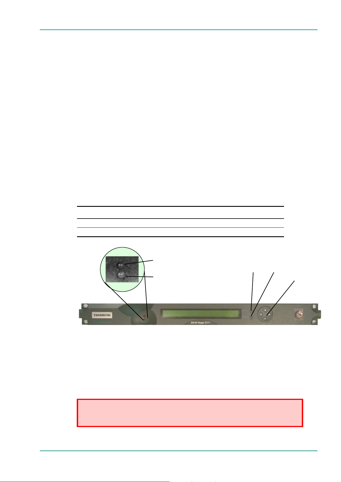
1.4.2 Front Panel Description
Front Panel Display, Navigation Keys, Softkeys, Keyboard
The 1U Encoder provides navigation keys to access and input data. The
2U Encoder provides a keypad and softkeys to access and input data.
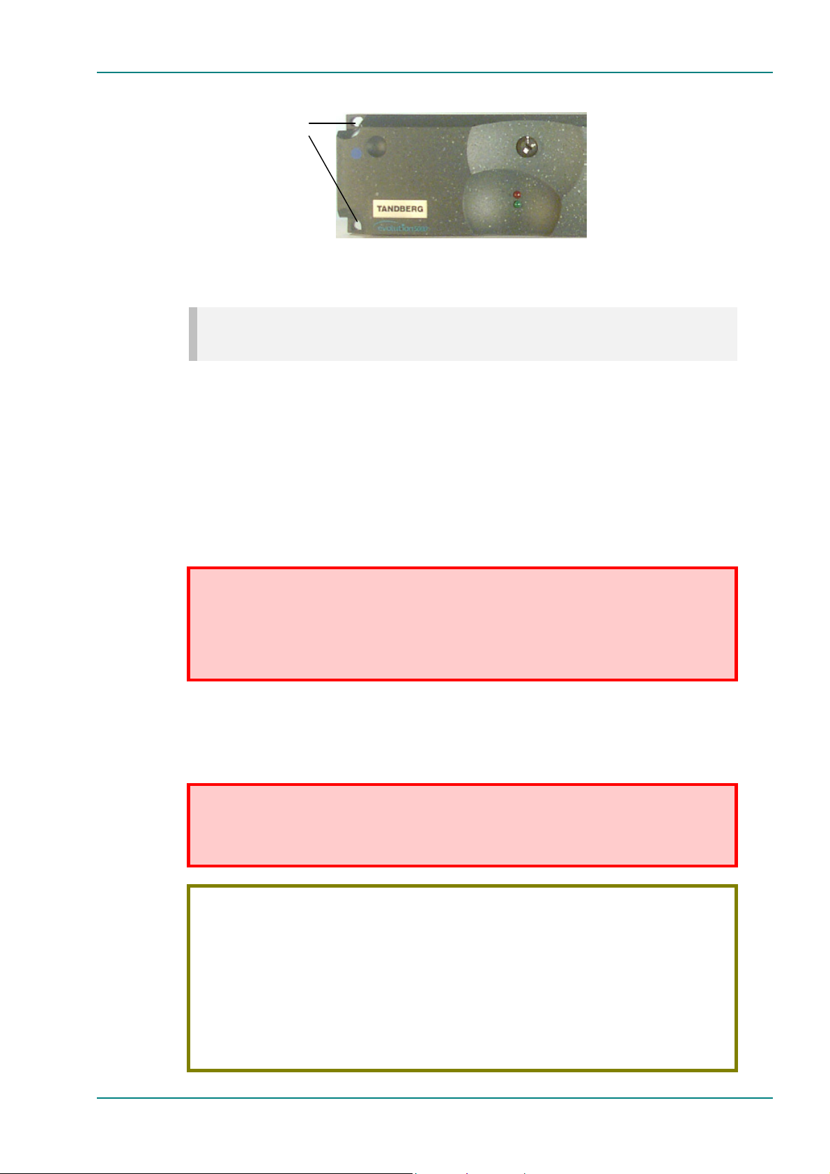
There are two LED indicators, located on the left of the front panel (see
Figure 1.5 and Figure 1.7).
The front panel display and navigation keys/softkeys/keyboard are used as
a local control method to set up and configure the Encoder (see Chapter 4,
Operating the Equipment Locally). They can also be used as quick method
for accessing the status of the equipment.
Table 1.4: Front Panel Indicators
Indicator Colour Description
Alarm Red This LED is lit when an alarm condition has been detected by the Encoder.
Power Green This LED is lit when power is being received by the Encoder.
Alarm (red)
Power (green)
Enter Cancel
Figure 1.5: 1U Encoder Front Panel Indicators
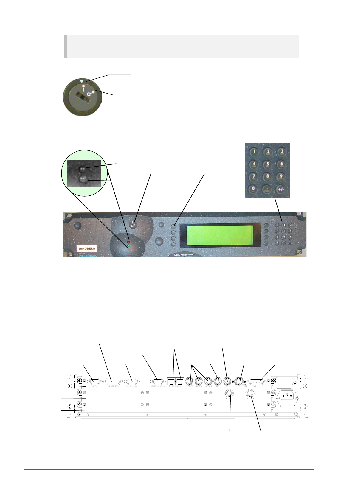
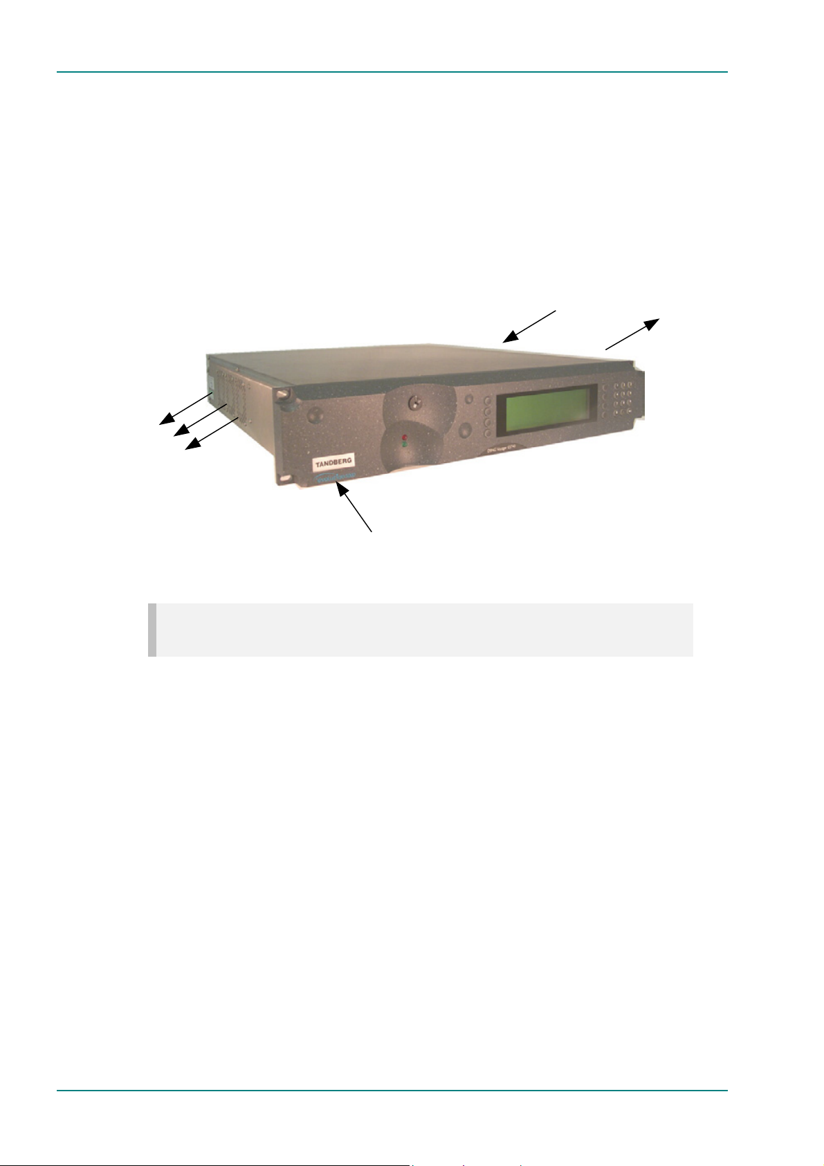
Power Supply Stand-by Switch
Navigation keys, to
select options
The use of this switch puts the Encoder into stand-by mode. It powers
down the supply rails of the display and internal circuits within the unit.
The switch type avoids accidental powering-down of the Encoder. For
normal use ensure that the I is always at the top (see Figure 1.6).
WARNING…
THIS IS NOT A MAINS SWITCH AND DOES NOT ISOLATE THE ENCODER FROM THE POWER
SUPPLY.
Page 1-14 Reference Guide: E57xx DSNG and DENG Voyager Encoder
ST.RE.E10076.3
Page 23
NOTE…
Current versions of the 1U Encoder may not have this switch fitted.
Introduction to the Basic Encoder
Figure 1.6: Stand-by Switch
Alarm (red)
Power (green)
On position
Stand-by position
Power Supply
Stand-by Switch
Softkeys, to select
options
Figure 1.7: 2U Encoder Front Panel Indicators
1.4.3 Rear Panel Description
Introduction
The Encoder provides connectors at the rear panel. All, except the power
connector, are physically located on the separate modules which comprise
the Encoder.
Base Board
Option Slots 4-5
Option Slot 1-3
RS-422 Data
Alarm
Option Slot 4 Option Slot 5
Option Slot 1
RS-232/ RS-485
Remote Control
RS-232 Data
Ethernet
Outputs
Option Slot 2
ASI
DI In
H Sync
IF OUT 1
Composite
Video
Option Slot 3
Audio Reference Out
IF OUT 2
Audio In and
Figure 1.8: E5750 (2U) Rear Panel Component Parts and Connectors
Reference Guide: E57xx DSNG and DENG Voyager Encoder Page 1-15
ST.RE.E10076.3
Page 24

Introduction to the Basic Encoder
1.4.4 Boards in the Basic Encoder
The basic Encoder contains two boards mounted horizontally in the
enclosure (see Table 1.5). Option modules can be fitted in the remaining
slots (see Equipment Models on page 1-3 and Chapter 3, Options and
Upgrades).
Table 1.5: Boards in the Basic Encoder
Model Number Card
E5714 S11171 Encoder Base Board
S12376 Tuneable QPSK Modulator
E5740-IF S11171 Encoder Base Board
S13716 70/140 MHz Satellite Modulator
E5714-LBAND S11171 Encoder Base Board
S13499 L-Band Satellite Modulator
E5740-LBAND S11171 Encoder Base Board
S13719 L-Band Satellite Modulator
E5750 S11171 Encoder Base Board
S12524 OFDM Modulator
Access to the modules or boards in the basic Encoder is not required for
normal operation and may invalidate the warranty.
Page 1-16 Reference Guide: E57xx DSNG and DENG Voyager Encoder
ST.RE.E10076.3
Page 25

Contents
Chapter 2
2. Installing the Equipment
2.1 Introduction...............................................................2-3
2.1.1 Read This First!............................................2-3
2.1.2 General.........................................................2-3
2.1.3 Site Requirements........................................2-3
Power Supplies.............................................2-3
Environment .................................................2-3
Lightning Protection......................................2-3
2.1.4 EMC Compliance Statements ......................2-3
EN 55022 / AS/NZS 3548.............................2-3
FCC..............................................................2-4
2.2 Preliminary Checks...................................................2-4
2.2.1 Mechanical Inspection..................................2-4
2.2.2 Moving the Equipment Safely.......................2-4
2.3 Installing the Equipment............................................2-4
2.3.1 Fixing Method...............................................2-4
2.3.2 Cable Routing...............................................2-5
2.3.3 Equipment Access........................................2-5
2.3.4 Ventilation.....................................................2-5
2.4 AC Mains Operating Voltage and Earthing...............2-7
2.4.1 AC Power Supply .........................................2-7
2.4.2 Power Cable and Earthing............................2-7
General.........................................................2-7
Protective Earth/Technical Earth..................2-7
Connecting the Encoder to the AC Power
Supply...........................................................2-8
2.5 -48 Vdc Power Supply...............................................2-9
2.5.1 DC Power Supply.........................................2-9
2.5.2 Location of the DC Input Connector.............2-9
2.5.3 Connecting the Equipment to the DC
Power Supply .............................................2-10
2.5.4 Protective Earth/Technical Earth................2-10
2.6 Signal Connections For the Basic Unit....................2-11
2.6.1 Introduction.................................................2-11
2.6.2 Connecting Up the Basic Encoder..............2-12
2.6.3 Power Supply..............................................2-13
2.6.4 Technical Earth...........................................2-13
2.6.5 Video Inputs................................................2-14
SDI IN .........................................................2-14
H SYNC ......................................................2-14
COMP VIDEO.............................................2-14
2.6.6 Audio Inputs................................................2-15
2.6.7 ASI OUT 1, 2 and 3 Outputs.......................2-16
2.6.8 Control Interfaces........................................2-16
Connection..................................................2-16
Ethernet #1 and #2 .....................................2-16
Alarm...........................................................2-16
Remote Control...........................................2-17
2.6.9 Data ............................................................2-18
RS-232 Connector......................................2-18
RS-422 Connector......................................2-18
Voyager Modulator Cards...........................2-19
2.6.10 Satellite Modulator IF Output (E5714 and
E5740 IF)....................................................2-20
IF Out (Main)...............................................2-20
IF Out (Monitor)...........................................2-20
2.6.11 Satellite Modulator L-Band Output
(E5740 LBAND and E5714)........................2-20
L-Band In ....................................................2-20
L-Band Out (Main) ......................................2-21
L-Band Out (Monitor)..................................2-21
ASI Input.....................................................2-21
2.6.12 OFDM Modulator Outputs (E5750).............2-22
IF Out 1.......................................................2-22
IF Out 2.......................................................2-22
Reference Guide: E57xx DSNG and DENG Voyager Encoder Page 2-1
ST.RE.E10076.3
Page 26

Installing the Equipment
2.7 Powering Up/Down..................................................2-23
2.7.1 Before Powering Up....................................2-23
2.7.2 Powering Up ...............................................2-23
2.7.3 Powering Down...........................................2-23
2.8 Setting the Encoder IP Address..............................2-23
2.8.1 Methods of Changing the Encoder IP
Address.......................................................2-23
2.8.2 From the Front Panel Menus......................2-24
2.8.3 Via Telnet....................................................2-24
List of Figures
Figure 2.1: Fitting the Encoder into a Rack................................... 2-5
Figure 2.2: Air Path Through the 2U Enclosure............................. 2-6
Figure 2.3: Connector Block for -48 Vdc Input.............................. 2-9
Figure 2.4: E5714 (1U) Rear Panel Component Parts and
Connectors.................................................................2-11
Figure 2.5: E5740-IF (2U) Rear Panel Component Parts and
Connectors.................................................................2-11
Figure 2.6: E5740-L-Band (2U) Rear Panel Component Parts
and Connectors..........................................................2-12
Figure 2.7: E5750 (2U) Rear Panel Component Parts and
Connectors.................................................................2-12
Figure 2.8: Equipment Connections for the Basic Unit................ 2-13
Figure 2.9: Main Telnet Menu...................................................... 2-24
List of Tables
Table 2.1: Supply Cable Wiring Colours........................................ 2-7
Table 2.2: SDI Connector............................................................2-14
Table 2.3: H SYNC Connector.................................................... 2-14
Table 2.4: COMP VIDEO Connector...........................................2-15
Table 2.5: Audio In Connector.....................................................2-15
Table 2.6: ASI OUT 1, 2 and 3 Connectors................................. 2-16
Table 2.7: Ethernet Connector ....................................................2-16
Table 2.8: Alarm Connector......................................................... 2-17
Table 2.9: Remote Control Connector (RS-232/ RS-485)...........2-17
Table 2.10: RS-232 Data Connector (Base Board) -
Asynchronous ............................................................2-18
Table 2.11: RS-422 Data Connector (Base Board) -
Synchronous.............................................................. 2-18
Table 2.12: Voyager Modulator Cards......................................... 2-19
Table 2.13: IF Out Connector (Main)...........................................2-20
Table 2.14: IF Output Connector (Monitor).................................. 2-20
Table 2.15: L-band In Connector.................................................2-20
Table 2.16: L-band Out (Main) Connector...................................2-21
Table 2.17: L-band Out (Monitor) Connector............................... 2-21
Table 2.18: ASI Input...................................................................2-22
Table 2.19: IF Out 1 Connector...................................................2-22
Table 2.20: IF Out 2 Connector...................................................2-22
Page 2-2 Reference Guide: E57xx DSNG and DENG Voyager Encoder
ST.RE.E10076.3
Page 27

2.1 Introduction
2.1.1 Read This First!
The Encoder must be handled carefully and thoughtfully to prevent safety
hazards and damage. It is usually supplied as part of a system installed by
TANDBERG Television engineers. In any case, ensure the personnel
designated to install the unit have the appropriate skills and knowledge. If
in any doubt, contact Customer Services.
Follow the instructions for installation and only use installation accessories
recommended by the manufacturers.
2.1.2 General
Installation of the Encoder is normally performed by TANDBERG Television
personnel. This chapter provides configuration and connection information
for planning installations, checking the final set-up in the event of a fault,
modifying the requirements or moving the equipment to another location.
In the event of problems, contact Customer Services.
Installing the Equipment
2.1.3 Site Requirements
Power Supplies
See Annex B, Technical Specification for a full specification.
Environment
See Annex B, Technical Specification for a full specification.
Do not install this product in areas of high humidity or where there is
danger of water ingress.
Lightning Protection
IF THE ENCODER HAS BEEN SUBJECT TO A LIGHTNING STRIKE OR POWER SURGE WHICH
HAS STOPPED IT WORKING, DISCONNECT THE POWER IMMEDIATELY. DO NOT REAPPLY
POWER UNTIL IT HAS BEEN CHECKED FOR SAFETY. IF IN DOUBT, CONTACT TANDBERG
TELEVISION CUSTOMER SERVICES.
Where appropriate, ensure this product has an adequate level of lightning
protection. Alternatively, during a lightning storm or when it is left
unattended and unused for long periods of time, unplug it from the supply
outlet and disconnect the output equipment. This prevents damage to the
product due to lightning and power line surges.
WARNING…
2.1.4 EMC Compliance Statements1
EN 55022 / AS/NZS 3548
This equipment is a Class A product. In a domestic environment this
product may cause radio interference in which case the user may be
required to take adequate measures.
1
The EMC information was correct at the time of manufacture. The EMC tests were performed with the Technical earth
attached.
Reference Guide: E57xx DSNG and DENG Voyager Encoder Page 2-3
ST.RE.E10076.3
Page 28

Installing the Equipment
FCC
This equipment has been tested and found to comply with the limits for a
Class A digital device, pursuant to Part 15 of the FCC Rules. These limits
are designed to provide reasonable protection against harmful interference
when the equipment is operated in a commercial environment.
This equipment generates, uses, and can radiate radio frequency energy
and, if not installed and used in accordance with the instruction manual,
may cause harmful interference to radio communications. Operation of this
equipment in a residential area is likely to cause harmful interference in
which case the user will be required to correct the interference at his own
expense.
2.2 Preliminary Checks
2.2.1 Mechanical Inspection
When taking delivery of an Encoder, check the equipment items delivered
against the enclosed delivery note. Inspect the equipment for damage in
transit. If in doubt, contact Customer Services (see Preliminary Pages).
NOTE…
Do not remove the covers of this equipment as doing so may invalidate any warranties, cause a safety
hazard and/or affect the EMC performance. It may also invalidate any safety tests. Check with
Customer Services beforehand.
2.2.2 Moving the Equipment Safely
Do not place this product on an unstable cart, stand,
bracket, or table. The product may fall, causing serious
injury and serious damage to the product. Use only with a
cart, stand, bracket or table recommended by TANDBERG
Television.
An appliance and cart combination should be moved with care. Quick
stops, excessive force, and uneven surfaces may cause the appliance and
cart combination to overturn.
Do not move or carry the equipment whilst it is still connected to the
supply or other leads, is live or is in operation.
2.3 Installing the Equipment
2.3.1 Fixing Method
The Encoder can be operated mounted in a 19-inch rack. Ensure that it is
firmly and safely located and has an adequate through-flow of air.
Slide the Encoder onto the chassis supports and affix to the rack by means
of an M6 x 18 mm panhead screw in each corner (see Figure 2.1).
Do not use this product as a support for any other equipment.
Page 2-4 Reference Guide: E57xx DSNG and DENG Voyager Encoder
ST.RE.E10076.3
Page 29
f
Location of screws to attach
Encoder to rack.
Same at the opposite side o
the Encoder.
Figure 2.1: Fitting the Encoder into a Rack
NOTE…
Current versions are not fitted with the Standby switch shown above.
2.3.2 Cable Routing
Power supply cables should be routed so that they are not likely to be
walked on or pinched by items placed upon or against them. Pay particular
attention to cables at plugs, convenience receptacles, and the point where
they exit from the appliance.
Installing the Equipment
Do not run ac power cables in the same duct as signal leads.
2.3.3 Equipment Access
BERYLLIUM COPPER FINGER STRIPS ARE USED IN THIS EQUIPMENT TO SEAL THE
ENCLOSURE FOR EMI PROTECTION. THIS ARRANGEMENT IS PERFECTLY SAFE DURING
NORMAL OPERATION. DO NOT FILE THE STRIPS OR OTHERWISE CAUSE THEM TO PRODUCE
DUST OR PARTICLES. ANY CUTS CAUSED BY THE STRIP SHOULD BE TREATED
Ensure that the Encoder is installed in such a way as to allow access to the
rear of the unit and the connectors.
2.3.4 Ventilation
NEVER PUSH OBJECTS OF ANY KIND INTO THIS EQUIPMENT THROUGH OPENINGS AS THEY
MAY TOUCH DANGEROUS VOLTAGE POINTS OR SHORT-OUT PARTS THAT COULD RESULT IN
A FIRE OR ELECTRIC SHOCK. NEVER SPILL LIQUID OF ANY KIND ON THE PRODUCT.
1. Openings in the cabinet are provided for ventilation and to ensure reliable operation of the product
and to protect it from overheating, and these openings must not be blocked or covered. This product
should never be placed near or over a radiator or heat register. This product should not be placed in
a built-in installation such as a rack unless proper ventilation is provided or the instructions have
been adhered to.
2. Do not install equipment so that the air intake of one aligns with the outlet on another. Provide
baffles and adequate spacing.
3. The fans contained within this unit are not fitted with a dust/insect filter. Pay particular attention to the
environment in which it is to be used.
WARNING...
APPROPRIATELY.
WARNING...
CAUTIONS...
Reference Guide: E57xx DSNG and DENG Voyager Encoder Page 2-5
ST.RE.E10076.3
Page 30
Installing the Equipment
The unit is designed for stationary or fixed use only. Ensure it is firmly and
safely located and has an adequate through-flow of air. Allow at least
50 mm free air-space at each side of the equipment. Units in racks can be
stacked without ventilation panels between. Racks containing stacked
equipment may need to be forced-air cooled to reduce the operating
ambient temperature. For stacking constraints contact Customer Services.
The 1U Encoder uses a similar air-flow path, with three fans on each side
of the unit. With both 1U and 2U units it is important not to block the front
air intake on the bottom-left corner of the front panel (see Figure 2.2).
Three fans mounted
at rear, left side of
unit
4
Warm air out
(left, rear)
Cool air in
(front – via bottom vent)
Do not block the air intake.
Figure 2.2: Air Path Through the 2U Enclosure
NOTE…
Cooling arrangements in current models may differ to those shown.
1
3
Cool air in
(right, rear)
2
Warm air out
(right, front)
Two fans mounted
at front, right side
of unit
Page 2-6 Reference Guide: E57xx DSNG and DENG Voyager Encoder
ST.RE.E10076.3
Page 31

Installing the Equipment
2.4 AC Mains Operating Voltage and Earthing
2.4.1 AC Power Supply
CAUTION...
This product should be operated only from the type of power source indicated on the marking label. If
you are not sure of the type of power supply to your business, consult a qualified electrical engineer or
your local power company.
See Annex B, Technical Specification for a full power supply specification.
There are no links or switches to be altered for operation from different ac
supplies.
2.4.2 Power Cable and Earthing
General
Check that the ac power cable is suitable for the country in which the
Encoder is to be used.
WARNINGS...
1. IF THE MOULDED PLUG FITTED TO THE MAINS CABLE SUPPLIED WITH THIS UNIT IS NOT
REQUIRED, PLEASE DISPOSE OF IT SAFELY. FAILURE TO DO THIS MAY ENDANGER LIFE
AS LIVE ENDS MAY BE EXPOSED IF THE REMOVED PLUG IS INSERTED INTO A MAINS
OUTLET.
2. POWER-SUPPLY CORDS SHOULD BE ROUTED SO THAT THEY ARE NOT LIKELY TO BE
WALKED ON OR PINCHED BY ITEMS PLACED UPON OR AGAINST THEM, PAYING
PARTICULAR ATTENTION TO CORDS AT PLUGS, CONVENIENCE RECEPTACLES, AND
THE POINT WHERE THEY EXIT FROM THE APPLIANCE.
The unit is supplied with three, detachable mains-supply cables fitted with
moulded plugs suitable for the USA, UK or Europe.
The wires in the mains cable are coloured in accordance with the wire
colour code shown in Table 2.1.
Table 2.1: Supply Cable Wiring Colours
UK
(BS 1363)
Earth: Green-and-yellow Green-and-yellow Green
Neutral: Blue Blue White
Live: Brown Brown Black
EUROPE
(CEE 7/7)
USA
(NEMA 5-15P)
Protective Earth/Technical Earth
WARNINGS...
1. THIS UNIT MUST BE CORRECTLY EARTHED THROUGH THE MOULDED PLUG SUPPLIED.
IF THE LOCAL MAINS SUPPLY DOES NOT HAVE AN EARTH CONDUCTOR DO NOT
CONNECT THE UNIT. CONTACT CUSTOMER SERVICES FOR ADVICE.
2. BEFORE CONNECTING THE UNIT TO THE SUPPLY, CHECK THE SUPPLY REQUIREMENTS
IN ANNEX B.
Reference Guide: E57xx DSNG and DENG Voyager Encoder Page 2-7
ST.RE.E10076.3
Page 32

Installing the Equipment
The unit has a Technical earth terminal (marked with ) located at the
rear panel. Its use is recommended. This is NOT a Protective earth for
electric shock protection. The terminal is provided to:
1. Ensure all equipment chassis fixed within a rack are at the same
Technical earth potential. To do this, connect a wire between the
Technical earth terminal and a suitable point on the rack.
2. Eliminate the migration of stray charges when connecting between
equipment.
Connecting the Encoder to the AC Power Supply
1. DO NOT OVERLOAD WALL OUTLETS AND EXTENSION CORDS AS THIS CAN RESULT IN A
RISK OF FIRE OR ELECTRIC SHOCK.
2. AS NO MAINS SWITCH IS FITTED TO THIS UNIT, ENSURE THE LOCAL AC POWER SUPPLY
IS SWITCHED OFF BEFORE CONNECTING THE SUPPLY CORD.
3. THE ENCODER IS NOT FITTED WITH AN ON/OFF SWITCH. ENSURE THAT THE SOCKETOUTLET IS INSTALLED NEAR THE EQUIPMENT SO THAT IT IS EASILY ACCESSIBLE.
FAILURE TO ISOLATE THE EQUIPMENT PROPERLY MAY CAUSE A SAFETY HAZARD.
WARNING...
IF THE TERMINAL SCREW HAS TO BE REPLACED, USE THE FOLLOWING:
1U ENCODER - M4 X 10 mm LONG POZIDRIV PANHEAD.
2U ENCODER - M5 X 12mm LONG POZIDRIV PANHEAD.
USING A LONGER SCREW MAY CAUSE A SAFETY HAZARD.
WARNINGS...
To connect the unit to the local ac power supply:
1. Ensure the local ac supply is switched OFF.
2. Ensure the correct fuse type and rating has been fitted to both the
equipment and the ac power cable.
3. Connect the ac power lead to the Encoder mains input connector and
then to the local mains supply.
Page 2-8 Reference Guide: E57xx DSNG and DENG Voyager Encoder
ST.RE.E10076.3
Page 33

2.5 -48 Vdc Power Supply
A
2.5.1 DC Power Supply
NOTE…
Only model M2/VOY/E5750/48V uses a dc power supply.
CAUTION...
This product should be operated only from the type of power source indicated on the marking label. If
you are not sure of the type of power supply to your business, consult a qualified electrical engineer.
This product uses a –48 Vdc power supply source (see Annex B, Technical
Specification for a full power supply specification.
2.5.2 Location of the DC Input Connector
The connector is located at the right-hand rear of the equipment.
Installing the Equipment
WARNING…
THE –48 VDC ENCODER IS NOT FITTED WITH AN ON/OFF SWITCH. ENSURE THAT THE SUPPLY
HAS A SUITABLE MEANS OF ISOLATION WHICH IS EASILY ACCESSIBLE. FAILURE TO
ISOLATE THE EQUIPMENT PROPERLY MAY CAUSE A SAFETY HAZARD.
Technical Earth
1U Encoder
Technical Earth
Fuse Carrier
Connector Block
Fuse
6.3
Equipment Side
— +
— +
2U Encoder
Connector Block
—48 V 0 V
Supply Side
Figure 2.3: Connector Block for -48 Vdc Input
The equipment fuse is held in an integral fuse carrier at the dc power inlet
at the rear of the Encoder. See Annex B, Technical Specification for dc fuse
information.
Reference Guide: E57xx DSNG and DENG Voyager Encoder Page 2-9
ST.RE.E10076.3
Page 34

Installing the Equipment
2.5.3 Connecting the Equipment to the DC Power Supply
Connect the Encoder to the local dc power supply as follows.
1. Local DC Power Supply
Ensure the local dc supply is isolated.
2. Encoder
Ensure the correct fuse is fitted.
3. Supply Cord
Connect the dc lead to the Encoder input connector and then to the
local dc power supply. Switch on the dc power supply.
2.5.4 Protective Earth/Technical Earth
The unit has a Technical earth terminal (marked with ) located at the
rear panel (see Figure 2.3). Its use is recommended. This is NOT a
Protective earth for electric shock protection. The terminal is provided to:
• Ensure all equipment chassis fixed within a rack are at the same
Technical earth potential. To do this, connect a wire between the
Technical earth terminal and a suitable point on the rack.
• Eliminate the migration of stray charges when connecting between
equipment.
WARNING...
IF THE TERMINAL SCREW HAS TO BE REPLACED, USE THE FOLLOWING:
1U ENCODER - M4 X 10 mm LONG POZIDRIV PANHEAD.
2U ENCODER - M5 X 12mm LONG POZIDRIV PANHEAD.
USING A LONGER SCREW MAY CAUSE A SAFETY HAZARD.
Page 2-10 Reference Guide: E57xx DSNG and DENG Voyager Encoder
ST.RE.E10076.3
Page 35

Installing the Equipment
2.6 Signal Connections For the Basic Unit
2.6.1 Introduction
All signal connectors are located at the rear panel of the Encoder. For a
detailed interface specification see Annex B, Technical Specification.
Always use the specified cables supplied for signal integrity and compliance
with EMC requirements (see Annex B, Technical Specification).
Base Board
IF Out Main
IF Out Monitor
Option Slot 2
RS-422
Alarm
Data
Data
RS-232/ RS-485
Remote Control
Ethernet RS-232
ASI Outputs
SDI In
Figure 2.4: E5714 (1U) Rear Panel Component Parts and Connectors
Alarm
RS-422
Data
RS-232
Data
RS-232/RS-485
Remote Control
Ethernet
ASI
Outputs
SDI In
H Sync
H Sync
Composite
Video
Composite
Video
Technical Earth
Audio In
and
Audio Reference Out
Audio In
and
Audio Reference Out
Base Board
Option Slots 4-6
Option Slot 1
Option Slot 4
Option Slot 1
Option Slot 5
Option Slot 6
IF Out
Main
IF Out
Monitor
TANDBERG
Television use
only
Figure 2.5: E5740-IF (2U) Rear Panel Component Parts and Connectors
Technical
Earth
Reference Guide: E57xx DSNG and DENG Voyager Encoder Page 2-11
ST.RE.E10076.3
Page 36

Installing the Equipment
Base Board
Option Slots 4-6
Option Slot 1
Alarm
RS-422
Data
RS-232
Data
Option Slot 4
Option Slot 1
RS-232/RS-485
Remote Control
Ethernet
Option Slot 5
ASI
Outputs
SDI In
H Sync
Composite
Option Slot 6
L-Band In
L-Band Out
TANDBERG
Television use
only
Figure 2.6: E5740-L-Band (2U) Rear Panel Component Parts and Connectors
RS-422
Data
Alarm
RS-232
Data
RS-232/RS-485
Remote Control
Ethernet
ASI
Outputs
SDI In
H Sync
Composite
Video
Audio In
and
Audio Reference Out
Video
Technical
Earth
Audio In
and
Audio Reference Out
Base Board
Option Slots 4-5
Option Slot 1
Option Slot 4
Option Slot 1
Option Slot 5
L-Band In
L-Band Out
Figure 2.7: E5750 (2U) Rear Panel Component Parts and Connectors
2.6.2 Connecting Up the Basic Encoder
Once the unit has been installed in its intended operating position, it is
ready to be connected up to the rest of the system equipment
(see Figure 2.8), providing it too has been installed (see the following for
pin-out details of the connectors).
Technical
Earth
Page 2-12 Reference Guide: E57xx DSNG and DENG Voyager Encoder
ST.RE.E10076.3
Page 37

Installing the Equipment
A
[
[
Serial Digital Interface
Studio Black and Burst
Analogue composite video
Audio input
AES/EBU Reference
10BaseT
10BaseT
RS-232/RS-485
RS-232 data input
RS-422 data input
Video Input
SDI IN
H SYNC
COMP VIDEO
Audio Input
AUDIO IN
Control
ETHERNET #1
ETHERNET #2
REMOTE CONTROL
Data
RS-232 DATA
RS-422 DATA
Encoder
Output
ASI OUT 1
ASI OUT 2
SI OUT 3
Alarm
ALARM
Modulator (IF)
E5740-IF]
OUT MAIN
OUT MONITOR
Modulator (L-band)
E5740-L Band]
L-BAND IN
L-BAND OUT MAIN
L-BAND OUT MONITOR
DVB/ATSC Transport stream output
DVB/ATSC Transport stream output
DVB/ATSC Transport stream output
Alarm
Main Output
Monitor Output
L-Band In
L-Band Monitor Output
L-Band Main Output
Figure 2.8: Equipment Connections for the Basic Unit
Do not move or install equipment whilst it is still attached to the mains
supply. Ensure ESD precautions are observed whilst interconnecting
equipment.
NOTE…
See Chapter 3 for information relating to Options and Upgrades.
2.6.3 Power Supply
Section 2.4, AC Mains Operating Voltage and Earthing provides details of
power supply connection, Protective earthing and safety. Read all the
instructions carefully and take note of all warnings and cautions.
2.6.4 Technical Earth
Connect the Encoder's Technical earth to a suitable point.
Reference Guide: E57xx DSNG and DENG Voyager Encoder Page 2-13
ST.RE.E10076.3
Page 38

Installing the Equipment
2.6.5 Video Inputs
SDI IN
A 75 Ω BNC connector provides a serial digital video
input to the unit. See Chapter 4, Operating the
Equipment Locally, Video Input Option for the types of
video and selection method. This input is terminated in
75 Ω.
The serial input supports error detection and handling (EDH) as defined by
the specification SMPTE RP 165-1994, ‘Error Detection Checkwords and
Status Flags for Use in Bit Serial Digital Interfaces for Television’.
For more information about EDH refer to Annex I, EDH Capability for E57xx
Encoders.
Table 2.2: SDI Connector
Pin Signal
Centre Video Input
Screen Ground
Impedance 75 Ω
H SYNC
Studio Black and Burst should be fed to the 75 Ω BNC
connector (H SYNC). This will then genlock the
Encoder to the Studio system. This method may be
required with some audio formats, or for locking
Encoders to an evolution 5000 Multiplexer. For details
on the genlocking system see Annex F, Audio Modes.
Table 2.3: H SYNC Connector
Pin Signal
Centre Video Input
Screen Ground
Impedance 75 Ω
COMP VIDEO
A 75 Ω BNC connector provides a high quality
analogue video input to the unit. See Chapter 4,
Operating the Equipment Locally, Video Input Option
for the types of video and selection method.
NOTE…
The input is differential to prevent 50 Hz/60 Hz hum.
Page 2-14 Reference Guide: E57xx DSNG and DENG Voyager Encoder
ST.RE.E10076.3
Page 39

Table 2.4: COMP VIDEO Connector
Pin Signal
Centre Video Input
Screen Video Input Return
Impedance 75 Ω
2.6.6 Audio Inputs
Connect the audio cable to the AUDIO IN
connector. The 15-way, D-type male connector is
used in different ways according to the audio input
and the encoding configuration selected.
The connector provides two stereo pairs. They may be independently
configured as either analogue or digital. The left channel is used to input
digital audio.
The Encoder is supplied with a break-out cable which plugs into this
connector, and provides a more convenient means of connecting the audio
signals via five connectors. There are four XLR female connectors, with the
fifth cable being a BNC which provides an AES/EBU 75 Ω digital reference
output.
Table 2.5: Audio In Connector
Installing the Equipment
Pin Signal Pin Signal
Analogue Digital Analogue Digital
1 Left Channel A (+) AES/EBU (A) (+) 9 Left Channel A (-) AES/EBU (A) (-)
2 Not connected 10 Right Channel A (+)
3 Right Channel A (-) 11 Not connected
4 Left Channel B (+) AES/EBU (B) (+) 12 Left Channel B (-) AES/EBU (B) (-)
5 Not connected 13 Right Channel B (+)
6 Right Channel B (-) 14 Not connected
7 AES/EBU
Reference (Signal)
8 Not connected
15 AES/EBU
Reference (Ground)
NOTES…
1. In analogue mode termination is either 20 kΩ or 600 Ω.
2. In AES/EBU mode termination is 110 Ω.
3. When the Encoder is powered down the digital channel is selected with 110 Ω termination.
4. The digital audio input does not support SPDIF.
5. In order to comply with EMC regulations, use the audio break-out cable supplied with the unit.
Reference Guide: E57xx DSNG and DENG Voyager Encoder Page 2-15
ST.RE.E10076.3
Page 40

Installing the Equipment
2.6.7 ASI OUT 1, 2 and 3 Outputs
Connect the Multiplexer or Modulator ASI cable to the
appropriate ASI OUT connector, using good quality
75 Ω coaxial cable (for example, BBC PSF 1/3).
A 75 Ω BNC connector provides the output from the Encoder.
Table 2.6: ASI OUT 1, 2 and 3 Connectors
Pin Signal
Centre Signal
Screen Ground
2.6.8 Control Interfaces
Connection
Operation of the Encoder from a TANDBERG Television control system is
via the Ethernet network running the Simple Network Management
Protocol (SNMP) protocol. Connect the ETHERNET connector to the
controller (for example, MEM). Local control is implemented through the
front panel keypad and display. See Chapter 4, Operating the Equipment
Locally for details of how to access the front panel menus.
Ethernet #1 and #2
An 8-way, RJ-45 connector provides a 10BaseT
Ethernet interface for communications with the MEM
for control and monitoring. The Encoder has a single
switched Ethernet channel. Ethernet#1 is selected as
default at power-up. If a carrier is not detected on
Ethernet#1 then the input switches to Ethernet#2.
This gives a redundant Ethernet control via two hubs.
Table 2.7: Ethernet Connector
Pin Signal Pin Signal
1 Tx Out (+) 4-5 Not connected
2 Tx Out (-) 6 Rx In (-)
3 Rx In (+) 7-8 Not connected
Alarm
If required, connect an external status monitoring
device to the ALARM connector.
A 9-way, D-type male connector provides an alarm
relay interface which can be used to send a signal to
remote equipment.
Page 2-16 Reference Guide: E57xx DSNG and DENG Voyager Encoder
ST.RE.E10076.3
Page 41

Table 2.8: Alarm Connector
Pin Signal Pin Signal
1 Ground 6 Fail (NO)
2 Fail (common) 7 Fail (NC)
3 Alarm (NO) 8 Alarm (common)
4 Alarm (+) (NC) 9 Reset 2 (internally grounded)
5 Reset 1
(internally pulled to
3.3 Vdc via 10 kΩ)
Fail
Common
Alarm
Common
Fail (NC)
Fail (NO)
Alarm (NC)
Alarm (NO)
3.3 V
10 kΩ
Reset 1
Reset 2
Installing the Equipment
NOTE…
NC = Normally Closed, NO = Normally Open, and refers to the relay contacts. Refer to Annex B for
details of the relay contact rating.
Remote Control
A 9-way, D-type male connector provides an
RS-232/RS-485 port for remote control of the
Encoder (see Serial Protocol Option). This
connector is wired as a DTE.
Table 2.9: Remote Control Connector (RS-232/ RS-485)
Remote (DTE) Encoder (DTE) Remote Control
Signal Name Signal Direction Pin Signal Name
1 Not connected
Transmit Data 2 Received Data (RS-232)
Received Data 3 Transmit Data (RS-232)
4 Not connected
Signal Ground 5 Signal Ground
Transmit Data B 6 Received Data B (RS-485)
Received Data A 7 Transmit Data A (RS-485)
Received Data B 8 Transmit Data B (RS-485)
Transmit Data A 9 Received Data A (RS-485)
NOTES…
1. Signal names are with respect to a DTE in accordance with the RS-232 and RS-485
specification. A is positive and B is negative.
2. A null modem connection must be used when connecting DTE together.
Reference Guide: E57xx DSNG and DENG Voyager Encoder Page 2-17
ST.RE.E10076.3
Page 42

Installing the Equipment
2.6.9 Data
RS-232 Connector
RS-232 data is available on the Base Board.
Table 2.10: RS-232 Data Connector (Base Board) - Asynchronous
Remote (DTE) Male Encoder RS-232 (DTE) Female
Signal Name Pin Signal Direction Pin Signal Name
1 1 Not connected
Received Data 2 2 Received Dat a
Transmit Data 3 3 Transmit Data
4 4 Not connected
Signal Ground 5 5 Signal Ground
6, 7, 8, 9 6, 7, 8, 9 Not connected
NOTES…
1. Signal names are with respect to a DTE in accordance with the RS-232 specification.
2. Remote pin numbers only apply to a 9-way D-type connector.
3. 25-way connectors have Received Data on pin 3 and Transmit Data on pin 2 (see RS –232
specification).
4. XON/OFF flow control may be used with this port.
RS-422 Connector
A 15-way, D-type female connector
provides an RS-422 synchronous, serial
communications data input interface.
Table 2.11: RS-422 Data Connector (Base Board) - Synchronous
Remote (DTE) Encoder RS-422 (DCE)
Signal Name Signal Direction Pin Signal Name
1 Not connected
Transmit Data A 2 Transmit Data A
3, 4, 5, 6 Not connected
4 Not connected
5 Not connected
6 Not connected
Transmit Clock A 7 Transmit Clock A
Signal Ground 8 Signal Ground
Transmit Data B 9 Transmit Data B
10, 11,
12, 13
Transmit Clock B 14 Transmit Clock B
15 Not connected
Not connected
Page 2-18 Reference Guide: E57xx DSNG and DENG Voyager Encoder
ST.RE.E10076.3
Page 43

Installing the Equipment
NOTE…
Signal names are with respect to a DTE in accordance with the RS-422 specification. A is positive and
B is negative.
Voyager Modulator Cards
Table 2.12 shows the modulator cards and associated Encoder Models.
Table 2.12: Voyager Modulator Cards
Encoder Product
(Marketing Code)
E5714
(M2/VOY/E5714 IF)
E5714
(M2/VOY/E5714 LBAND
E5740
(M2/VOY/E5740 IF)
E5740
(M2/VOY/E5740 LBAND)
E5745
(M2/VOY/E5745/IF)
E5745 L-Band
(M2/EOM2/E5745/LBAND)
Size S Number and
Marketing Code Number
of Modulator Option
Card
1U S12376 1/3 Width IF
(M2/EOM2/QPSK2)
1U S13499 1/3 Width L-Band
(M2/EOM2/QPSKLBAND)
2U S13716 2/3 Width IF
(M2/EOM2/SM3IF)
2U S13719 2/3 Width L-Band
(M2/EOM2/SM3LBAND)
2U S12376 1/3 Width IF
(M2/EOM2/QPSK2)
2U S13499 1/3 Width L-Band
(M2/EOM2/QPSKLBAND)
Number
of ASI
Inputs
Rate
Adaptation
Available
Modulation
Schemes
24 Vdc
BUC
Power
Available
0 No BPSK/QPSK N/A
1 Yes BPSK/QPSK No
2 No BPSK/QPSK
8BPSK/16QA
M
2 No BPSK/QPSK
8BPSK/16QA
M
0 No BPSK/QPSK N/A
1 Yes BPSK/QPSK yes
N/A
Yes
Reference Guide: E57xx DSNG and DENG Voyager Encoder Page 2-19
ST.RE.E10076.3
Page 44

Installing the Equipment
2.6.10 Satellite Modulator IF Output (E5714 and E5740 IF)
IF Out (Main)
75 Ω BNC socket provides an IF output.
Table 2.13: IF Out Connector (Main)
Item Specification
Connector type BNC 75 Ω Female
Type Analogue
Connector designation IF OUT M A I N
Pin-outs Centre
Screen
IF Out (Monitor)
75 Ω BNC socket provides an IF output used for
monitoring.
IF Output
Ground
Table 2.14: IF Output Connector (Monitor)
Item Specification
Connector type BNC 75 Ω Female
Type Analogue
Connector designations IF O U T M ON I T O R
Pin-outs Centre
Screen
IF Output
Ground
2.6.11 Satellite Modulator L-Band Output (E5740 LBAND
and E5714)
L-Band In
50 Ω SMA female connector provides an L-band input to
allow another L-band signal to be summed with the
modulator output.
CAUTION…
Do not connect large diameter cable to the SMA connector as this may cause mechanical damage.
Table 2.15: L-band In Connector
Item Specification
Connector Type 50 Ω SMA Female
Type Analogue
Connector designation L-Band In
Pin-outs Centre Signal
Screen Ground
Page 2-20 Reference Guide: E57xx DSNG and DENG Voyager Encoder
ST.RE.E10076.3
Page 45

Installing the Equipment
L-Band Out (Main)
50 Ω SMA female connector provides the main L-band
output. Both models can provide a 10 MHz reference
frequency output and the E5740 can also source +24 Vdc
at up to 500 mA to power a block up-converter (BUC) An
LED is illuminated when the +24 Vdc up-converter power
is switched on.
CAUTION…
Do not connect large diameter cable to the SMA connector as this mat cause mechanical damage.
Please use the cable provided (part number S12696).
NOTE…
DC supply not available in 1U L Band version.
Table 2.16: L-band Out (Main) Connector
Item Specification
Connector Type 50 Ω SMA Female
Type Analogue
Connector designation L-Band Out Main
Pin-outs Centre Signal
Screen Ground
CAUTION…
A 24 V dc voltage is present at the L-BAND OUT MAIN connector when the up-converter dc power is
switched on. Do not connect this output directly to a spectrum analyser or other sensitive equipment.
The use of a dc block is recommended.
L-Band Out (Monitor)
75 Ω F-type female provides an L-band monitoring
output which is –30 dB relative to the main output.
Table 2.17: L-band Out (Monitor) Connector
Item Specification
Connector Type 75 Ω F-type Female
Type Analogue
Connector designation L-Band Out Monitor
Pin-outs Centre Signal
Screen Ground
ASI Input
This connector is available with the following models:
E5740-IF and L-Band, and the E5714 L-band (when fitted with the
S13716/S13719).
Connector details for the ASI input are given in Table 2.18.
Reference Guide: E57xx DSNG and DENG Voyager Encoder Page 2-21
ST.RE.E10076.3
Page 46

Installing the Equipment
Table 2.18: ASI Input
Item Specification
Connector Type 75 Ω BNC Female
Type Analogue
Connector designation ASI IN 1, ASI IN 2
Pin-outs Centre Signal
Screen Ground
2.6.12 OFDM Modulator Outputs (E5750)
IF Out 1
A 75 Ω BNC socket provides a 70 MHz IF output.
Table 2.19: IF Out 1 Connector
Item Specification
Connector Type BNC 75 Ω Female
Type Analogue
Connector designation IF Out 1
Pin-outs Centre Signal
Screen Ground
IF Out 2
A 75 Ω BNC socket provides a 70 MHz IF output used for
monitoring.
Table 2.20: IF Out 2 Connector
Item Specification
Connector Type BNC 75 Ω Female
Type Analogue
Connector designation IF Out 2
Pin-outs Centre Signal
Screen Ground
Page 2-22 Reference Guide: E57xx DSNG and DENG Voyager Encoder
ST.RE.E10076.3
Page 47

2.7 Powering Up/Down
2.7.1 Before Powering Up
Before powering up the Encoder, check that:
1. The unit has been installed in a suitable location.
2. The unit has been connected to external equipment and power supply,
as required.
3. The power supply has been checked and a good earth provided.
4. The correct fuse type and rating has been fitted to the equipment and,
for the ac supply version, the ac power cable.
2.7.2 Powering Up
To power up the Encoder:
1. Turn on the local power supply. The Encoder executes a series of
power-up initialisation and self-test routines.
2. Confirm that the green Power LED is lit and that the red Alarm LED is
unlit.
Installing the Equipment
3. Ensure that the Stand-by switch, if fitted, is set to On (see Chapter 1,
Introduction, Figure 1.8).
After the boot period the Encoder Input Monitor screen is displayed.
NOTES…
1. The fans on the Encoder can be temperature controlled so may not be on if the ambient
temperature is low. Refer to Annex B, Technical Specification for more information.
2. During initialisation invalid PIDs may appear momentarily in the transport stream.
2.7.3 Powering Down
To power down the Encoder remove the power supply connection at the
rear of the unit.
2.8 Setting the Encoder IP Address
2.8.1 Methods of Changing the Encoder IP Address
If, for any reason, the IP address has to be changed, this can be achieved
via the front panel menus (see Section 4.7.4 Remote Control Menu) or by
Telnet (see Section 2.8.3, Via Telnet). The user may also set the network
mask.
NOTE…
The new IP address is only accepted after the Encoder is repowered.
Reference Guide: E57xx DSNG and DENG Voyager Encoder Page 2-23
ST.RE.E10076.3
Page 48

Installing the Equipment
2.8.2 From the Front Panel Menus
To access the IP Address option from the front panel menus, press the IP
Address softkey in the Remote Control Menu. Edit the IP address via the
keypad and then press the Enter softkey.
IP Address
← Left Encoder IP Address : +
→ Right `172.16.248.91’ —
O Enter ●
O Update using softkeys Quit ●
2.8.3 Via Telnet
A Telnet program is supplied with Microsoft Windows. To communicate with
the Encoder through Telnet:
1. From DOS, type telnet <IP address>.
2. Press Enter for the user name, and press Enter for the password.
3. The Main Telnet Menu is displayed.
Figure 2.9: Main Telnet Menu
4. Press <a> System, <b> Remote Control, <a> IP Address.
5. Enter the new value and press Enter.
6. Reset the Encoder.
Page 2-24 Reference Guide: E57xx DSNG and DENG Voyager Encoder
ST.RE.E10076.3
Page 49

Contents
Chapter 3
3. Options and Upgrades
3.1 What’s Available........................................................ 3-3
3.1.1 Option Functions .......................................... 3-3
3.1.2 Limitations on Number of Option Modules
(2U Only) ......................................................3-4
Overview....................................................... 3-4
E5740 Option Slots....................................... 3-4
E5750 Option Slots....................................... 3-4
3.1.3 Limitations on Use of Option Modules..........3-4
3.1.4 How to See Which Options are
Fitted/Enabled .............................................. 3-5
3.2 Bit-rate Limits With Reflex Licence and/or
Performance Upgrade............................................... 3-5
3.3 Basic Interoperable Scrambling System - BISS
(M2/EDCOM2/BISS) ................................................. 3-5
3.4 Additional Audio and Linear PCM Option
(M2/EOM2/AUDLIN2) ...............................................3-6
3.4.1 Overview....................................................... 3-6
3.4.2 Assembly ...................................................... 3-7
Rear Panel.................................................... 3-7
Audio In Connector.......................................3-7
3.5 Remux Option (M2/EOM2/REMUX) ......................... 3-9
3.5.1 Overview....................................................... 3-9
3.5.2 Assembly ...................................................... 3-9
Rear Panel.................................................... 3-9
DVB ASI IN 1, 2 and 3 Connectors ............ 3-10
DVB ASI OUT 1 Connector ........................3-10
3.5.3 Stages of Remultiplexing............................3-10
3.5.4 Function of Remultiplexer...........................3-12
3.5.5 Using the Remultiplexer ............................. 3-13
3.5.6 ATSC Remultiplexing ................................. 3-13
3.5.7 Setting Bit-rates and Avoiding Overflow ..... 3-13
3.5.8 What to do if Overflow Occurs....................3-14
3.6 SD Decoder Option (M2/EOM2/DEC) .....................3-14
3.6.1 Overview .....................................................3-14
3.6.2 Assembly.....................................................3-15
Rear Panel ..................................................3-15
ASI Out .......................................................3-15
SDI Video Out .............................................3-15
Composite Video Output.............................3-16
Audio Output ...............................................3-16
RS-232/RS-422 Data Output ......................3-17
3.7 QPSK Demodulator (M2/EOM2/QPSKDEMOD) .....3-17
3.7.1 Overview .....................................................3-17
3.7.2 Assembly.....................................................3-18
Rear Panel ..................................................3-18
3.8 16QAM Demodulator (M2/EOM2/SATDEMOD)......3-19
3.9 IP Output Card (M2/EOM2/IP) ................................3-19
3.10 Vocality Card Option (M2/EOM2/COMMS/FXS
IF In.............................................................3-18
RF In ...........................................................3-18
ASI In ..........................................................3-18
3.8.1 Overview .....................................................3-19
3.8.2 Assembly.....................................................3-19
Rear Panel ..................................................3-19
L-Band Inputs..............................................3-19
3.9.1 Overview .....................................................3-19
3.9.2 Assembly.....................................................3-20
Rear Panel ..................................................3-20
ASI In ..........................................................3-20
RS-232 Control ...........................................3-21
ASI Out .......................................................3-21
Ethernet Output...........................................3-21
and M2/EOM2/COMMS/FXO).................................3-22
Reference Guide: E57xx DSNG and DENG Voyager Encoder Page 3-1
ST.RE.E10076.3
Page 50

Options and Upgrades
3.10.1 Overview .....................................................3-22
3.10.2 Assembly.....................................................3-23
Rear Panel ..................................................3-23
Telephone Line Connectors........................3-23
Data Connector...........................................3-24
Supervisor Port Connector..........................3-24
Link Connector............................................3-25
LAN Connector ...........................................3-25
3.10.3 Connecting the DSNG Communications
Card to the Encoder....................................3-25
3.10.4 Configuring the Encoder for the DSNG
Communications Card.................................3-26
3.11 GPI Card (M2/EOM2/GPI).......................................3-26
3.11.1 Overview .....................................................3-26
3.11.2 Assembly (1U Panel Version Shown) .........3-27
3.11.3 Connector ...................................................3-27
3.12 Triax Option (M2/EOM2/TRIAX)..............................3-28
3.12.1 Introduction .................................................3-28
3.12.2 Description ..................................................3-28
3.13 Software Options.....................................................3-29
3.13.1 M2/ESO2/NR ..............................................3-29
3.13.2 M2/ESO2/PU ..............................................3-29
3.13.3 M2/ESO2/VBR ............................................3-29
3.13.4 M2/ESO2/422 .............................................3-29
3.13.5 M2/ESO2/RAS ............................................3-29
3.13.6 M2/ESO2/ACON .........................................3-29
3.13.7 M2/ESO2/AC3 ............................................3-29
3.13.8 M2/ESO2/SM38PSK ...................................3-29
3.13.9 M2/ESO2/SM316QAM ................................3-29
3.13.10 M2/ESO2/8PSKDEMOD.............................3-29
3.13.11 M2/ESO2/16QAMDEMOD..........................3-29
3.13.12 M2/ESO2/LSYM..........................................3-30
3.13.13 M2/ESO2/DVB-MHP...................................3-30
3.13.14 M2/ESO2/DTS ............................................3-30
3.13.15 M2/ESO2/525VBIDATA ..............................3-30
3.13.16 M2/ESO2/SCTE-35 SPLICE POINTS ........3-30
Table 3.3: Minimum Bit-rates With and Without Performance
Upgrade........................................................................ 3-5
Table 3.4: Audio In Connector....................................................... 3-8
Table 3.5: DVB ASI In Connector................................................ 3-10
Table 3.6: DVB ASI Out Connector............................................. 3-10
Table 3.7: ASI Out Connector ..................................................... 3-15
Table 3.8: SDI Video Out Connector ........................................... 3-16
Table 3.9: Composite Video Connector....................................... 3-16
Table 3.10: Audio Output Connector ........................................... 3-16
Table 3.11: RS-232/RS-422 Data Output Connector .................. 3-17
Table 3.12: IF In Connector......................................................... 3-18
Table 3.13 RF In Connector ........................................................ 3-18
Table 3.14: ASI In Connector ...................................................... 3-18
Table 3.15: L-Band Input Connector ........................................... 3-19
Table 3.16: ASI In Connector ...................................................... 3-20
Table 3.17: ASI Out Connector ................................................... 3-21
Table 3.18: RJ-45 Connector ...................................................... 3-21
Table 3.19: Telephone/Line Connector ....................................... 3-24
Table 3.20: Data Connector ........................................................ 3-24
Table 3.21: Supervisor Connector............................................... 3-25
Table 3.22: Link Connector ......................................................... 3-25
Table 3.23: LAN Connector ......................................................... 3-25
Table 3.24: GPI Connector.......................................................... 3-27
List of Figures
Figure 3.1: Additional Audio and Linear PCM Option
(M2/EOM2/AUDLIN2) .................................................. 3-7
Figure 3.2: Remux Option (M2/EOM2/REMUX)............................ 3-9
Figure 3.3: Block Diagram – One Stage of Remultiplexing ......... 3-11
Figure 3.4: Block Diagram – Two Stages of Remultiplexing ....... 3-11
Figure 3.5: Remultiplexer Block Diagram.................................... 3-12
Figure 3.6: IP Output Protocol Stack........................................... 3-20
Figure 3.7: DSNG Comms Card Interconnections ...................... 3-22
Figure 3.8: Vocality Card Option (M2/EOM2/COMMS/FXS
and M2/EOM2/COMMS/FXO).................................... 3-23
Figure 3.9: DSNG Comms Card Connections............................. 3-26
Figure 3.10: General Purpose Interface M2/EOM2/GPI.............. 3-27
List of Tables
Table 3.1: Hardware Option Module Positions.............................. 3-3
Table 3.2: Software Options.......................................................... 3-4
Page 3-2 Reference Guide: E57xx DSNG and DENG Voyager Encoder
ST.RE.E10076.3
Page 51

3.1 What’s Available
3.1.1 Option Functions
The basic Encoder functionality can be enhanced with the inclusion of
options, hardware and software.
Each hardware option module consists of a horizontally mounted PCB with
rear panel connector space (except the M2/EDCOM2/BISS which has no
external connectors and does not occupy an option slot). At reset, the
software of the Encoder detects which modules are fitted and configures
them as necessary. The modules can be fitted into the positions indicated
in Table 3.1.
When the appropriate software option has been purchased it is enabled in
the Encoder, which resets and displays the appropriate menu items. See
Table 3.2 for the software options.
Table 3.1: Hardware Option Module Positions
Options and Upgrades
Marketing Code Name Assembly
Part No
Card
Part No
Slot No.
in 1U
Slot No.
in 2U
Max No. of
Cards in 2U
Daughter Card Options
M2/EDCOM2/BISS BISS1 scrambling
option - Mode 0, 1
and BISS-E only with secure key
entry
S12284 S11484 — —
Hardware Options
M2/EOM2/AUDLIN2 Additional Audio +
Linear PCM
M2/EOM2/REMUX
(supported by Encoder
software version 2.2 and
later)
M2/EOM2/DEC SD Decoder Card S11753 S11385 - 6 1
M2/EOM2/QPSK
DEMOD
M2/EOM2/SAT
DEMOD
M2/EOM2/IP IP Output Card S12794 S12822 1 3, 5, 6 1
M2/EOM2/COMMS/FXS DSNG Comms
M2/EOM2/COMMS/FXO DSNG Comms
M2/EOM2/GPI GPI Card S13586 1, 2 1, 2, 3, 4, 5, 6 1
M2/EOM2/TRIAX TRIAX Card - - - - -
Remux Option
Module
QPSK Demod
Card
16QAM Demod
Card
card (FXS)
card (FXO)
S13181 S13167 2 1, 4, 5 3
S12449 S10655 2 1 1
S11852 - - 5 1
S12640 - - 5 1
S13117 - - 1 and 4 1
S13217 - - 1 and 4 1
NOTE…
Empty option slots must be fitted with a blanking plate.
1
BISS is implemented according to Tech 3290 March 2000 and BISS-E is implemented according to Tech 3292 April
2001.
Reference Guide: E57xx DSNG and DENG Voyager Encoder Page 3-3
ST.RE.E10076.3
Page 52

Options and Upgrades
Table 3.2: Software Options
Marketing Code Name Used
in 1U
M2/ESO2/NR Noise Reduction ✔ ✔
M2/ESO2/PU Performance Upgrade/Bit-rate <1.5 Mbit/s ✔ ✔
M2/ESO2/VBR VBR Licence ✔ ✔
M2/ESO2/422 4:2:2 ✔ ✔
M2/ESO2/RAS RAS (Remote Authorisation System) ✔ ✔
M2/ESO2/ACON Auto Concatenation ✔ ✔
M2/ESO2/AC3 Dolby Digital (AC-3) ✔ ✔
M2/ESO2/SM38PSK 8PSK Modulation E5714-LBAND ✔
M2/ESO2/SM316QAM 16QAM Modulation E5714-LBAND ✔
M2/ESO2/8PSKDEMOD 8PSK Demodulation (only applicable if M2/EOM2/SAT
DEMOD is fitted)
M2/ESO2/16QAM
DEMOD
M2/ESO2/LSYM Low Symbol Rate operation (minimum reduced to
M2/ESO2/DVB-MHP MHP Timing Events
M2/ESO2/DTS DTS Audio
M2/ESO2/525VBIDATA NABTS and GEMSTAR 2.0 VBI extraction
M2/ESO2/SCTE-35
SPLICE POINTS
16QAM Demodulation (only applicable if
M2/EOM2/SATDEMOD is fitted)
300 ksym/s)
SCTE35 DPI ✔ ✔
— ✔
— ✔
✔ (not
E5714 IF)
✔ ✔
✔ ✔
✔ ✔
Used
in 2U
✔
3.1.2 Limitations on Number of Option Modules (2U Only)
Overview
If the Remux option is not fitted then there can be a maximum of three
option modules.
If the Remux option module is fitted there can be a maximum of two other
option modules.
E5740 Option Slots
Base Board
Option Slot 4 Option Slot 5 Option Slot 6
Option Slot 1 Satellite Modulator
E5750 Option Slots
Base Board
Option Slot 4 Option Slot 5 OFDM Modulator
Option Slot 1 Option Slot 2 Option Slot 3
3.1.3 Limitations on Use of Option Modules
Although both BISS (M2/EDCOM2/BISS) and RAS (M2/ESO2/RAS) may be
present in the Encoder, only one may be used at a time.
Page 3-4 Reference Guide: E57xx DSNG and DENG Voyager Encoder
ST.RE.E10076.3
Page 53

Options and Upgrades
3.1.4 How to See Which Options are Fitted/Enabled
The Encoder has a number of hardware and software options (see Table 3.1
and Table 3.2). To see which are fitted/enabled refer to the Build Menu
(see Chapter 4, Operating the Equipment Locally, Figure 4.9).
3.2 Bit-rate Limits With Reflex Licence and/or Performance Upgrade
A user with a REFLEX licence (M2/ESO2/VBR) but no Performance Upgrade
(M2/ESO2/PU) will be able to get lower bit-rates than 1.5 Mbit/s. This only
occurs in Seamless modes. However, because the Performance Upgrade
has not been bought the picture quality will be reduced (see Table 3.3).
Table 3.3: Minimum Bit-rates With and Without Performance Upgrade
Performance
Upgrade
8 8
8
9
9 9 0.256 Mbit/s Depends on Coding Mode Depends on Coding Mode
Reflex
Licence
1.5 Mbit/s 1.5 Mbit/s
9
8
B
Non-seamless
min
Modes
1.5 Mbit/s 1.5 Mbit/s
0.256 Mbit/s Depends on Coding Mode Not Possible
B
min
(Front Panel, SNMP)
Seamless Modes
B
Seamless Modes
min
(Reflex, MEM)
2
Not Possible
2
Depends on Coding Mode
NOTE…
B
is the minimum bit-rate that can be set.
min
3.3 Basic Interoperable Scrambling System BISS (M2/EDCOM2/BISS)
With the appropriate configuration, the Encoder can use the Basic
Interoperable Scrambling System (BISS
transport stream. This system has been developed by the European
Broadcasting Union (EBU) as an open scrambling system.
BISS has three main levels of operation: Mode 1, Mode 2 and Mode 3.
Mode 0 corresponds to no scrambling. BISS-E is also available in Build
version 2.2.0 and later.
3
) to scramble the outgoing
NOTE…
Only Modes 0 and 1 are available at Build version 2.1.0. Modes 2 and 3 are not supported.
BISS Mode 1 operation uses a fixed value for the control word to scramble
the services in the transport stream from the Encoder. To descramble the
transmission, the Decoder needs to have the matching control word value.
2
1.5 Mbit/s, but possibly higher if limited by Coding Mode.
3
BISS is implemented according to EBU Tech 3292 May 2002. BISS-E is available from Build version 2.2.0 and later.
Reference Guide: E57xx DSNG and DENG Voyager Encoder Page 3-5
ST.RE.E10076.3
Page 54

Options and Upgrades
The BISS Module (M2/EDCOM2/BISS) comprises Assembly S12284 and
Card S11484.
NOTES…
1. This option module is installed as a daughter card to the Base Board, with no external
connectors and does not use an option slot
2. The BISS software must also be enabled in the Encoder (see Customer Services).
BISS scrambling (when fitted) is enabled and controlled via the Setup/Mux
Menu (see Chapter 4, Operating the Equipment Locally, Section 4.12.14).
3.4 Additional Audio and Linear PCM Option (M2/EOM2/AUDLIN2)
3.4.1 Overview
The Additional Audio option module supplements the audio encoding
functionality of the Encoder. This module supports audio standards MPEG-1
(layer 2), Dolby Digital (AC-3), Linear PCM, Dolby Digital (AC-3)
Pass-through, Dolby E Pass-through and DTS Pass-through. The module
can take in audio as either stereo analogue or digital AES/EBU (on left
channel only) via a 15-way D-type connector provided on its rear panel.
Alternatively, any two of the four pairs of embedded AES/EBU channels
extracted from the video can be routed to the module for encoding. This
option supports all the standard bit-rates and encoding modes associated
with each compression standard.
M2/EOM2/AUDLIN2 supports 12 dB, 15 dB, 18 dB and 24 dB audio clip
level.
The Audio Menu associated with this option is described in Chapter 4,
Operating the Equipment Locally, Section 4.9. In the Audio Setup Menu
additional options are displayed for Audio XA and Audio XB, where X is the
option slot number where the module is fitted.
Refer to Annex F, Audio Modes for details of Encoder locking to ensure
correct performance.
Page 3-6 Reference Guide: E57xx DSNG and DENG Voyager Encoder
ST.RE.E10076.3
Page 55

3.4.2 Assembly
A
A
A
eference
A
Rear Panel
Analogue Composite Video
Serial Digital Interface
Audio Input
COMP VIDEO
SDI IN
UDIO IN
Encoder
ASI OUT 1
ASI OUT 2
ASI OUT 3
Options and Upgrades
Output Transport Stream
Output Transport Stream
Output Transport Stream
Mono 1 / Stereo 1 Right
Mono 2 / Stereo 1 Left
Mono 3 / Stereo 2 Right
Mono 4 / Stereo 2 Left
NOTE…
The AES/EBU reference signal is provided for backwards compatibility only. When using E57xx
Encoders use the reference signal provided by the Base Board.
Figure 3.1: Additional Audio and Linear PCM Option (M2/EOM2/AUDLIN2)
The Additional Audio option module comprises Assembly S13181 and Card
S13167. See Table 3.1 for the slots that it can be installed in.
Audio In Connector
Connect the audio cable to the AUDIO IN
connector. The 15-way, D-type male connector
is used in different ways according to the audio
input and the encoding configuration selected.
Additional Audio
Option
Pins 3, 10
Pins 1, 9
Pins 6, 13
Pins 4, 12
ES/EBU Digital
ES/EBU Digital B
Additional Audio
Option
Pins 7, 15
Pins 1, 9
Pins 4, 12
AES/EBU
r
Digital Audio Inputs
The connector provides two stereo pairs. They may be independently
configured as either analogue or digital. The left channel is used to input
digital audio.
Reference Guide: E57xx DSNG and DENG Voyager Encoder Page 3-7
ST.RE.E10076.3
Page 56

Options and Upgrades
Table 3.4: Audio In Connector
Pin Signal Pin Signal
Analogue Digital Analogue Digital
1 Left Channel A (+) AES/EBU (A) (+) 9 Left Channel A (-) AES/EBU (A) (-)
2 Not connected 10 Right Channel A (+)
3 Right Channel A (-) 11 Not connected
4 Left Channel B (+) AES/EBU (B) (+) 12 Left Channel B (-) AES/EBU (B) (-)
5 Not connected 13 Right Channel B (+)
6 Right Channel B (-) 14 Not connected
7 AES/EBU
8 Not connected
NOTES…
3. In analogue mode termination is either 20 kΩ or 600 Ω.
4. In AES/EBU mode termination is 110 Ω (default).
5. When the Encoder is powered down the digital channel is selected with 110 Ω termination.
6. The digital audio input does not support SPDIF.
Reference (Output
Signal)
15 AES/EBU
Reference (Ground)
CAUTION…
To ensure EMC compliance, use the audio connector supplied with the Encoder.
Page 3-8 Reference Guide: E57xx DSNG and DENG Voyager Encoder
ST.RE.E10076.3
Page 57

3.5 Remux Option (M2/EOM2/REMUX)
p
A
3.5.1 Overview
NOTE…
The M2/EOM2/REMUX Remux Option Module is supported by Build version 2.2.0 and later.
The Remux option module is capable of accepting up to three separate
transport streams via ASI connectors, and one transport stream from the
host Encoder. The maximum permissible data rate of each input transport
stream is 50 Mbit/s. Some or all of the services in the input transport
streams are then multiplexed together to produce a Multiple Channels Per
Carrier (MCPC) output at up to 50 Mbit/s. For a specification of this
interface see Annex B, Technical Specification
3.5.2 Assembly
Rear Panel
Options and Upgrades
The Remux option module comprises assembly S12449 and Card S10655.
See Table 3.1 for the slots that it can be installed in.
Analogue Composite Video
Serial Digital Interface
Audio Input
Input Transport Stream 1
Input Transport Stream 2
Input Transport Stream 3
DVB-ASI OUT is
disabled.
CAUTION…
When remultiplexing, be aware that both PIDs and Service Names will be remapped according to the
Host Encoder input used.
Encoder
COMP VIDEO
SDI IN
UDIO IN
[Host]
ASI OUT 1
ASI OUT 2
ASI OUT 3
Remux Option
DVB ASI IN 1
DVB ASI IN 2
DVB ASI IN 3
DVB ASI OUT 1
Output Transport Stream
Output Transport Stream
ut Transport Stream
Out
Output is disabled
The output is a multiplex of the
three input transport streams of
the Remux option and the
transport stream produced by the
host Encoder.
Figure 3.2: Remux Option (M2/EOM2/REMUX)
Reference Guide: E57xx DSNG and DENG Voyager Encoder Page 3-9
ST.RE.E10076.3
Page 58

Options and Upgrades
DVB ASI IN 1, 2 and 3 Connectors
A 75 Ω BNC connector provides an input to the unit.
Table 3.5: DVB ASI In Connector
Pin Signal
Centre Signal
Screen Ground
NOTE…
When connecting the inputs, always start from DVB ASI IN 1 and work upwards.
DVB ASI OUT 1 Connector
A 75 Ω BNC connector provides an output from the unit.
Table 3.6: DVB ASI Out Connector
Pin Signal
Centre Signal
Screen Ground
NOTE…
This output is disabled.
3.5.3 Stages of Remultiplexing
The Remultiplexer is capable of combining four inputs. Three inputs are in
the form of ASI feeds to the rear panel, the fourth input is fed from the
host Encoder (or primary Encoder). This basic configuration, using a single
stage of remultiplexing, means that four Encoder services (or streams) can
be combined together in the output. Figure 3.3 shows a typical satellite
system using one stage of remultiplexing.
Page 3-10 Reference Guide: E57xx DSNG and DENG Voyager Encoder
ST.RE.E10076.3
Page 59

Options and Upgrades
A
A
A
A
A
A
A
A
VIDEO (ANALOGUE)
VIDEO (DIGITAL)
AUDIO
SYNC DATA
ASYNC DATA
VIDEO (ANALOGUE)
VIDEO (DIGITAL)
AUDIO
SYNC DATA
ASYNC DATA
VIDEO (ANALOGUE)
VIDEO (DIGITAL)
AUDIO
SYNC DATA
ASYNC DATA
Contributing
Encoders
Service 2
Service 3
Service 4
SI
SI
SI
VIDEO (ANALOGUE)
VIDEO (DIGITAL)
AUDIO
SYNC DATA
ASYNC DATA
Primary (Master)
Encoder with
Remux
Service 1
Up-link equipment
(including
Up-converter and
High Power
Amplifier)
Tx
IF Output
NOTE…
IF Output contains 4 services:
Service 1 + Service 2 + Service 3 + Service 4.
Contributing
Encoders
Service 3
Service 4
Service 5
Contributing
Encoders
Service 7
Service 8
Service 9
Contributing
Encoders
Service 11
Service 12
Service 13
Figure 3.3: Block Diagram – One Stage of Remultiplexing
Similarly, if two stages of remultiplexing are introduced, thirteen Encoders
can be combined, providing up to thirteen services in the remultiplexed
output. This is the maximum number of services that can be provided
using this system, see Figure 3.4.
Up-link equipment
(including
Up-converter and
High Power
Amplifier)
Tx
IF Output
NOTE…
IF Output contains 13 services.
SI (x3)
SI (x3)
SI (x3)
Encoder
with Remux
Service 2
Encoder
with Remux
Service 6
Encoder
with Remux
Service 10
SI (x4)
Encoder
with Remux
ASI (x4)
Service 1
SI (x4)
Figure 3.4: Block Diagram – Two Stages of Remultiplexing
Reference Guide: E57xx DSNG and DENG Voyager Encoder Page 3-11
ST.RE.E10076.3
Page 60

A
p
deo
Audio
A
p
A
p
A
Options and Upgrades
3.5.4 Function of Remultiplexer
It is the function of the Remultiplexer to combine the locally generated
host services with the externally supplied input services, connected via ASI
inputs to the rear of the unit. If the Service ID (DVB) or Program Number
(ATSC), PIDs or service names, of two or more of the services clash, the
Remultiplexer can remap the Service ID or program number, remap PIDs,
and alter the service names to resolve the clash.
If a new service is detected on any input, and it clashes with an existing
service, it is the new service’s Service ID or Program Number, PIDs, or
Service Name that are remapped to resolve the conflict. Service names are
made unique by the addition of a number, for example ‘Default Service’
may be renamed ‘Default Service [2]’.
The way the Remultiplexer deals with user requests to remap PIDs ia as
follows:
If there is an attempt to move/remap a PID to a PID already being used,
the Remultiplexer allows this to happen, and automatically remaps the
element that was on that PID.
Vi
Video
Encoder
Audio
Encoder
Host
Mux
Rate
Remux
SI
In
ut
Remux
SI
In
ut
Remultiplexer
Dual Port
Ram
Output
-
ASI
Driver
Modulator
SI Output
IF Output
Remux
SI
In
ut
Figure 3.5: Remultiplexer Block Diagram
Page 3-12 Reference Guide: E57xx DSNG and DENG Voyager Encoder
ST.RE.E10076.3
Page 61

3.5.5 Using the Remultiplexer
Set the output bit-rate to the required value in the Setup/Mux Menu.
Connect transport streams that are to be combined (remultiplexed) with
the host Encoder’s services to the ASI inputs on the rear of the unit.
NOTE…
It is possible to remultiplex any DVB or ATSC compliant transport stream but at the time of publication,
only transport streams generated by TANDBERG Television equipment are guaranteed to work when
fed to the Remultiplexing module.
The equipment will automatically detect the services on these inputs. The
list of detected services is displayed in the Setup/Mux Menu.
Each service can be individually switched ‘Off’, ‘On’, or ‘On with
scrambling’. If the service is set to ‘Off’, then there is no trace of the
service in the output transport stream. New services can be set to default
to either Off or On. If it was connected to the Remultiplexer the last time
the Encoder was powered, then it assumes its previous state.
It is possible to remultiplex transport streams that have already been
scrambled by BISS encryption, but it is not possible to remultiplex
transport streams that have already been scrambled using RAS encryption.
Also it is not possible to scramble a service that has already been
scrambled.
Options and Upgrades
3.5.6 ATSC Remultiplexing
The Remultiplexer can work with ATSC compliant transport streams. It
remaps the services following the ATSC program paradigm.
The Encoder can be configured to generate the PSIP for the output
transport stream. It generates the minimum number of tables to give an
ATSC compliant output transport stream, i.e. Event Information Tables
(EIT) 0, 1, 2 and 3, the System Time Table (STT), the Rating Region Table
(RRT), the Master Guide Table (MGT), and either the Cable Virtual Channel
Table (CVCT) or the Terrestrial Virtual Channel Table (TVCT), depending on
the delivery descriptor set. It will not pass through any tables that are
present on the ASI input transport streams.
Alternatively, an external PSIP generator can be connected to one of the
Remultiplexer inputs and the remultiplexer programmed to pass through a
range of PIDs, thus inserting the PSIP into the output transport stream.
For more information about using the Remux card in ATSC with internal
and external PSIP see Annex H, Use of Remux Card in ATSC.
3.5.7 Setting Bit-rates and Avoiding Overflow
Overflow is the condition in which the total of the contributing service
bit-rates, (including the host mux), exceeds the output bit-rate of the
primary remultiplexing unit.
NOTE…
Only useful packets (e.g. video, audio and data, etc) count towards the bit-rate of the contributing
service bit-rates, not null packets.
Reference Guide: E57xx DSNG and DENG Voyager Encoder Page 3-13
ST.RE.E10076.3
Page 62

Options and Upgrades
The easiest way to configure the bit-rates to avoid overflow, is as follows:
1. Divide the 188 byte output bit-rate of the primary (master)
remultiplexing unit, (this can be found in the Setup/Mux/Remux
Module/Output Bit-rate), by the number of contributing services
(including the primary service). Such that:
O/P Rate (188) / N = Host Rate (188)
[Where N = number of services to be combined including primary]
2. Then set the Host Rates (188) of each contributing unit and the master
unit to equal the calculated Host Rate.
If the above procedure is followed, an equal bit-rate is allocated to each
contributing unit. By setting the host rates, the video and audio bit-rates
will be automatically adjusted to suit.
The amount of spare bit-rate and input bit-rate that has been used in the
Remultiplexer can be monitored using the bar graph indicators in the
Setup/Mux/Remux Module Menu.
3.5.8 What to do if Overflow Occurs
If an ‘Overflow Error’ is indicated on the equipment, then the incoming
contributing bit-rate exceeds the outgoing bit-rate. To avoid corruption
reduce the incoming bit-rate by either removing services, (turn the service
Off or remove the ASI input), or reduce the bit-rate of the incoming
service.
3.6 SD Decoder Option (M2/EOM2/DEC)
3.6.1 Overview
NOTES…
1. The M2/EOM2/DEC SD Decoder Option is supported by Build version 3.1 and later.
2. This option module only fits into option slot 6 in the E5740, and must always be accompanied by
a demodulator option module in slot 5.
This option module is a complete MPEG-2 standard definition decoder,
capable of decoding 422P@ML and MP@ML. It can provide analogue or
digital video and audio outputs, as well as synchronous and asynchronous
data outputs. In conjunction with a demodulator option module, it provides
a complete satellite monitoring receiver within the E5740 Encoder.
Page 3-14 Reference Guide: E57xx DSNG and DENG Voyager Encoder
ST.RE.E10076.3
Page 63

3.6.2 Assembly
Rear Panel
ASI Out
A 75 Ω female BNC connector provides an ASI
output of the transport stream being decoded by
the SD Decoder.
NOTE…
If the 16QAM demodulator is being used the ASI Out will be in burst mode.
Table 3.7: ASI Out Connector
Options and Upgrades
Item Specification
Connector Type 75 Ω BNC Female
Connector designation ASI Out
Pin-outs Centre Signal
Screen Ground
SDI Video Out
A 75 Ω female BNC connector provides an SDI video
output that conforms to ITU-R BT.656.
Reference Guide: E57xx DSNG and DENG Voyager Encoder Page 3-15
ST.RE.E10076.3
Page 64

Options and Upgrades
Table 3.8: SDI Video Out Connector
Item Specification
Connector Type 75 Ω BNC Female
Connector designation SDI Out
Pin-outs Centre Signal
Screen Ground
Composite Video Output
A 75 Ω female BNC connector provides a composite
video output. See Annex B, Technical Specification
for a list of supported video standards.
Table 3.9: Composite Video Connector
Item Specification
Connector Type 75 Ω BNC Female
Connector designation COMP VIDEO
Pin-outs Centre Signal
Screen Ground
Audio Output
A 15-way D-type socket provides the audio output.
Table 3.10: Audio Output Connector
Item Specification
Connector Type 15-way D-type Socket
Connector designation AUDIO OUT
Pin-outs 1 Ch 1 Left Analogue+/Ch 1 Digital+
2 Analogue Ground
3 Ch 1 Right Analogue -
4 Ch 2 Left Analogue+/Ch 2 Digital+
5 Analogue Ground
6 Ch 2 Right Analogue -
7 Reserved
8 Analogue Ground
9 Ch 1 Left Analogue-/Ch 1 Digital-
10 Ch 1 Right Analogue +
11 Analogue Ground
12 Ch 2 Left Analogue-/Ch 2 Digital-
13 Ch 2 Right Analogue +
14 Analogue Ground
15 Reserved
Page 3-16 Reference Guide: E57xx DSNG and DENG Voyager Encoder
ST.RE.E10076.3
Page 65

RS-232/RS-422 Data Output
A 9-way D-type socket provides the data outputs.
Table 3.11: RS-232/RS-422 Data Output Connector
Item Specification
Connector Type 9-way D-type Socket
Connector designation RS232/RS422 DATA
Pin-outs 1 RS422_CLK_A
2 RS232_RXD
3 RS232_TXD
4 No Connection
5 Ground
6 RS422_CLK_B
7 No Connection
8 RS422_DATA_A
9 RS422_DATA_B
Options and Upgrades
3.7 QPSK Demodulator (M2/EOM2/QPSKDEMOD)
3.7.1 Overview
NOTE…
The M2/EOM2/QPSKDEMOD QPSK Demodulator Option is supported by Build version 3.1 and later.
The module allows the Encoder to receive and demodulate satellite
transmissions that comply to EN 300 421 (DVB-S). It must be used with an
SD Decoder Module (M2/EOM2/DEC), which takes and decodes the
transport stream produced by the demodulator.
The module has three inputs; an IF input that operates over a frequency
range of 50 MHz to 180 MHz, and –20 dBm to –40 dBm input power, and
two L-Band inputs that operate over a frequency range of 950 MHz to 2150
MHz, and –25 dBm to –65 dBm input power.
It can normally receive signals with symbol rates in the range 1 to 45
Msymbol/s, but if the low symbol rate option (M2/EOS2/LSYM) is
purchased this can be expanded to cover 0.3 to 45 Msymbol/s.
Reference Guide: E57xx DSNG and DENG Voyager Encoder Page 3-17
ST.RE.E10076.3
Page 66

Options and Upgrades
3.7.2 Assembly
Rear Panel
IF In
A 75 Ω female BNC connector provides an IF Input.
Table 3.12: IF In Connector
Item Specification
Connector Type 75 Ω BNC Female
Connector designation IF IN
Pin-outs Centre Signal
Screen Ground
Ω
ASI IN
RF In
Two 75 Ω F-type female connectors provide
RF inputs.
Table 3.13 RF In Connector
Item Specification
Connector Type 75 Ω F-type Female
Connector designation RF 1, RF 2
Pin-outs Centre Signal
Screen Ground
ASI In
A 75 Ω female BNC connector provides an ASI input.
Table 3.14: ASI In Connector
Item Specification
Connector Type 75 Ω BNC Female
Connector designation ASI IN
Pin-outs Centre Signal
Screen Ground
Page 3-18 Reference Guide: E57xx DSNG and DENG Voyager Encoder
ST.RE.E10076.3
Page 67

Options and Upgrades
3.8 16QAM Demodulator (M2/EOM2/SATDEMOD)
3.8.1 Overview
The module allows the Encoder to receive and demodulate satellite
transmissions that comply to EN 300 421 (DVB-S), and EN 301 210
(DVB-DSNG). It must be used with an SD Decoder Module
(M2/EOM2/DEC), which takes and decodes the transport stream produced
by the demodulator. The module has two L-band inputs that operate over
a frequency range of 950 MHz to 2150 MHz, and –25 dBm to –65 dBm
input power. It can decode signals with symbol rates in the range 1 to 45
Msymbol/s. It is capable of demodulating 8PSK, and 16QAM transmissions,
as well as QPSK transmissions, but these are software options.
3.8.2 Assembly
Rear Panel
L-Band Inputs
Two 75 Ω F-type female connectors provide L-band inputs.
Table 3.15: L-Band Input Connector
Item Specification
Connector Type 75 Ω F-type Female
Connector designation L-Band Input 1, L-Band Input 2
Pin-outs Centre Signal
Screen Ground
3.9 IP Output Card (M2/EOM2/IP)
3.9.1 Overview
The IP Output card provides a 10/100 BaseT Ethernet port, out of which
the transport stream generated by the Encoder can be output in UDP
packets at up to 50 Mbit/s.
The mapping of MPEG-2 transport stream packets into IP data frames is
done according to the protocol stack shown in Figure 3.6.
NOTE…
More support has been given in V2.8.x of the IP Output Card in V3.6.x of the Encoder. This is
accessed using menu items on the IP menu tree from the front panel, telnet and web interfaces.
● The IP output can be turned off using the “IP Output” menu item.
● A “Line Mode” menu item allows the setting to be either “Fixed” or “Auto”.
Reference Guide: E57xx DSNG and DENG Voyager Encoder Page 3-19
ST.RE.E10076.3
Page 68

Options and Upgrades
Figure 3.6: IP Output Protocol Stack
MPEG- 2
Transport
Stream
MPEG-2/DVB Layer
UDP – User Datagram Protocol TCP/UDP
Transport Layer - IP
Link Layer – 10/100-baseT Ethernet
Between one and seven MPEG-2 transport stream packets can be put in
each UDP packet. The data link layer is Ethernet according to
IEEE 802.3/802.3u (auto-sensing 10/100 Mbit/s, twisted pair, via RJ-45
connector).
3.9.2 Assembly
Rear Panel
ASI In
A 75 Ω female BNC connector provides an ASI input.
NOTE…
This connector is not used.
Table 3.16: ASI In Connector
Item Specification
Connector Type 75 Ω BNC Female
Connector designation ASI IN
Pin-outs Centre Signal
Screen Ground
Page 3-20 Reference Guide: E57xx DSNG and DENG Voyager Encoder
ST.RE.E10076.3
Page 69

RS-232 Control
A 3.5mm socket provides a debug interface.
NOTE…
This connector is for TANDBERG Television use only.
ASI Out
A 75 Ω female BNC connector provides an ASI output.
NOTE…
This connector is not used.
Table 3.17: ASI Out Connector
Item Specification
Connector Type 75 Ω BNC Female
Connector designation ASI OUT
Pin-outs Centre Signal
Screen Ground
Options and Upgrades
Ethernet Output
An RJ-45 connector provides a 10/100 BaseT
Ethernet port.
Table 3.18: RJ-45 Connector
Item Specification
Connector Type RJ-45
Connector designation 10/100 BT
Pin-out 1 Tx Out (+)
2 Tx Out (-)
3 Rx In (+)
4 Not Connected
5 Not Connected
6 Rx In (-)
7 Not Connected
8 Not Connected
Reference Guide: E57xx DSNG and DENG Voyager Encoder Page 3-21
ST.RE.E10076.3
Page 70

Options and Upgrades
3.10 Vocality Card Option (M2/EOM2/COMMS/FXS and M2/EOM2/COMMS/FXO)
3.10.1 Overview
The DSNG Communications Card adds bi-directional telephone, data and IP
interfaces to an E5740 Encoder. There are two variants of the card, one
provides FXS connectivity, which allows standard telephones to be plugged
into the unit. The other provides FXO connectivity, which allows the unit to
be connected to a PABX. Normally an FXS variant would be deployed in the
field, with an FXO variant being used at the downlink site to connect into
the office telephone system. Both variants allow the first four channels to
be alternatively configured to operate as four-wire, Tie-line interfaces. The
cards are four channel as standard but can be software upgraded to
provide eight telephone channels. See Table 3.1 for the slots that it can be
installed in.
OMT & Waveguide Switch
HPA
Upconverter
Sat Modulator Demodulator
Encoder
E5740
LNB
L-Band Splitter
SD Decoder
DSNG Comms
Card
Telephone, RS422 Data & IP
OMT & Waveguide Switch
HPA
Upconverter
Sat Modulator Demodulator
Encoder
E5740
LNB
L-Band Splitter
SD Decoder
DSNG Comms
Card
Telephone, RS422 Data & IP
Figure 3.7: DSNG Comms Card Interconnections
The card multiplexes all the input channels into a single synchronous
RS-422 data channel that is connected to the Encoder’s RS-422 data input,
and then put into the transport stream transmitted via the satellite
modulator. The E5740 must also be fitted with a satellite demodulator and
SD Decoder to provide a return data path. The RS-422 data from the SD
Decoder is demultiplexed by the DSNG communications card to provide
return data for all the telephone, data and IP interfaces.
Page 3-22 Reference Guide: E57xx DSNG and DENG Voyager Encoder
ST.RE.E10076.3
Page 71

For details regarding configuring this card via the supervisor port refer to
the DSNG Comms card documentation provided on the Reference CD.
3.10.2 Assembly
Rear Panel
TEL/LIN
8
765
21
3 4
DAT
Options and Upgrades
VOCALITY INTERNATIONAL
LIN
SUPERVISO
COMMS
MODULE
STATUS
LA
VI68900
Figure 3.8: Vocality Card Option (M2/EOM2/COMMS/FXS and M2/EOM2/COMMS/FXO)
Telephone Line Connectors
Eight 8-way RJ-45 connectors provide the analogue voice/fax telephone
lines. In the four channel variant the top four connectors are not activated.
With the FXS variant, telephone lines 1 to 4 can be configured to operate
in either FXS or E&M (Tie-line) mode. Telephone Lines 5 to 8 can only
operate in FXS mode.
With the FXO variant, telephone lines 1 to 4 can be configured to operate
in either FXO or E&M (Tie-line) mode. Telephone Lines 5 to 8 can only
operate in FXO mode.
FXS mode is used to connect to a circuit that requires a ringing voltage (a
subscriber port). This may be a telephone or PABX trunk port, which
operates on 2-wire circuits. For UK users, a British Telecommunications
master Socket must be connected to the port in order to ring standard UK
telephones, since no ring capacitor is included in the interface.
Interfaces to subscriber telephones of other countries usually can be
connected directly to the SNG Comms card, since the telephones have an
integral ringing capacitor.
FXO mode configures the interface to accept DC current or ring voltages,
and so allows it to be connected to a PABX. Tie-line mode allows the
telephone line to be connected to the Tie-line card of a PABX via a
four-wire speech interface together with four wires for the E&M interface.
WARNING…
THE TELEPHONE LINE CONNECTORS HAVE A SAFETY STATUS OF TNV (EN 60950-1:2001
SECTION 2.3). THESE MAY ONLY BE CONNECTED TO PORTS OF A SIMILAR SAFETY STATUS.
DUE TO THE HAZARDOUS VOLTAGES THAT CAN OCCUR ON TELEPHONE LINES, IT IS
ESSENTIAL THAT THE ENCODER CHASSIS IS EARTHED BEFORE CONNECTING TO THE
TELEPHONE LINE.
Reference Guide: E57xx DSNG and DENG Voyager Encoder Page 3-23
ST.RE.E10076.3
Page 72

Options and Upgrades
Table 3.19: Telephone/Line Connector
4-Wire Tie-line Mode 2-Wire FXS/FXO Mode
Pin Signal Signal
1 MREF
2 M
3 RXA
4 TXRXA TIP
5 TXRXB RING
6 RXB
7 E
8 EREF
Data Connector
A 15-way, D-type female connector provides a
data port that supports a number of different
serial interface standards (see Table 3.20 and the
Vocality documentation). The data port can be
software configured as either a DTE or a DCE.
Table 3.20: Data Connector
Pin Signal Name DTE DCE
V.11 RS449 V.35 RS530 V.24
Shield Shield Shield Shield Shield Shield C C
1 GND GND GND GND GND C C
2 T(A) SDA SDA SDA TXD O I
3 CA) RSTA DTR RSTA DTR O I
4 R(A) RDA RDA RDA RXD I O
5 I(A) RRA DCD RRA DCD I O
6 S(A) RTA SCRA SCRA RXC I O
7 - STA SCTA SCTA TXC I O
8 - TTA SCTEA SCTEA EXTXC O I
9 T(B) SDB SDB SDB - O I
10 C(B) RSTB - RSTB - O I
11 R(B) RDB RDB RDB - I O
12 I(B) RRB - RRB - I O
13 S(B) RTB SCRB SCRB - I O
14 - STB SCTB SCTB - I O
15 - TTB SCTEB SCTEB - O I
Supervisor Port Connector
A 3-way, 3.5mm socket provides an RS-232 supervisor port, which allows
a PC to configure the card, (see Vocality document for details).
The supervisor port operates at 9600 baud, 8 data bits, no parity, one stop
bit with no flow control.
Page 3-24 Reference Guide: E57xx DSNG and DENG Voyager Encoder
ST.RE.E10076.3
Page 73

Options and Upgrades
Table 3.21: Supervisor Connector
Pin Signal
1 (Tip) Transmit (Out)
2 (Ring) Receive {In)
3 (Shield) Ground
Link Connector
A 15-way, D-type female connector provides the RS-422 interface to the
Encoder motherboard and the SD Decoder.
Table 3.22: Link Connector
Pin Signal
1
2
3 Transmit Data A
4
5
6
7 Transmit Clock A
8 Ground
9 Transmit Data B
10
11
12
13
14 Transmit Clock B
15
LAN Connector
An 8-way RJ-45 connector provides a 10/100baseT Ethernet port. The card
acts as a static IP router.
Table 3.23: LAN Connector
Pin Signal
1 Tx+
2 Tx-
3 Rx+
4 Shield
5 Shield
6 Rx-
7 Shield
8 Shield
3.10.3 Connecting the DSNG Communications Card to the
Reference Guide: E57xx DSNG and DENG Voyager Encoder Page 3-25
ST.RE.E10076.3
Page 74

Options and Upgrades
Encoder
The DSNG communications card requires an external cable to be fitted to
connect it to the Encoder. This cable is supplied with the option card.
• The 15-way, D-type male labelled Link should be connected to the
• The 15-way, D-type male labelled RS-422 Data should be connected
• The 9-way, D-type male labelled RS-232/RS-422 Data should be
socket labelled Link on the SNG Comms card.
to the socket labelled RS-422 Data on the Encoder base board.
connected to the socket labelled RS-232/RS-422 Data on the SD
Decoder card.
RS-422 Data
Link
Figure 3.9: DSNG Comms Card Connections
RS-232/RS-422 Data
3.10.4 Configuring the Encoder for the DSNG
Communications Card
The multiplexed communications data to be transmitted is sent from the
DSNG Communications card into the RS-422 data input of the Encoder.
The Encoder’s RS-422 data input must be switched on, and the bit-rate set
to match the SNG Comms card aggregate port data rate.
The multiplexed communications data received from the satellite is output
from the RS-232/RS-422 data port on the SD Decoder card. This requires
no special configuration, other than to be tuned to the appropriate satellite
channel, and for the correct service to be selected.
3.11 GPI Card (M2/EOM2/GPI)
3.11.1 Overview
The GPI Card connector allows various specific Encoder functions to be
controlled using contact closure inputs. In addition, contact closure outputs
are available for future use.
• 8 Contact Closure Inputs (intended to operate at TTL level signals) with
input protection. The controlled functions are software assigned.
• 2 Contact Closure Outputs which can be either open circuit or
connected to the common output. Each output has inverted or noninverted contacts
Page 3-26 Reference Guide: E57xx DSNG and DENG Voyager Encoder
ST.RE.E10076.3
Page 75

3.11.2 Assembly (1U Panel Version Shown)
A
r
Options and Upgrades
GPI Connecto
Analogue Composite Video
Serial Digital Interface
Audio Input
COMP VIDEO
SDI IN
UDIO IN
Encoder
(1U Slot: 1, 2
2U Slot: 1, 2, 4, 5)
ASI OUT 1
ASI OUT 2
ASI OUT 3
Output Transport Stream
Output Transport Stream
Output Transport Stream
GPI
Figure 3.10: General Purpose Interface M2/EOM2/GPI
Card Option
GPI
Contact Closure Inputs and Outputs
- 2 Contact Closure Outputs
- 8 Sensed Inputs
3.11.3 Connector
Table 3.24: GPI Connector
Item Specification Item Specification
Connector Type 15-way D-type Male Connector designation GPI
Pin-out 1 Input 0 Pin-out 9 GND
2 Input 1 10 Output 1 NI
3 Input 2 11 Output 1 Common
4 Input 3 12 Output 1 I
5 Input 4 13 Output 2 NI
6 Input 5 14 Output 2 Common
7 Input 6 15 Output 2 I
8 Input 7
Reference Guide: E57xx DSNG and DENG Voyager Encoder Page 3-27
ST.RE.E10076.3
Page 76

Options and Upgrades
3.12 Triax Option (M2/EOM2/TRIAX)
3.12.1 Introduction
This option is for the E5750 Encoder only.
The card is designed to work in conjunction with the COFDM Modulator
fitted to the E5750 Encoder in order to provide a TRIAX connection to
external equipment.
3.12.2 Description
The card takes in 70 MHz IF from the modulator and the 48 Vdc power
from an external power supply. It also accepts control information from the
control bus of the E5750.
The 70 MHz signal is passed through onto the TRIAX output connector. The
DC power is added to this so that external, downstream equipment (SHF
up-converter and power amplifier) that is typically mounted close to the
transmit antenna can be powered.
Additionally, the TRIAX adaptor also makes it possible to control the
external equipment from the front panel of the E5750. This is achieved
using a data carrier at 400 MHz. Modems are fitted internally within the
TRIAX adaptor and the external equipment, making it possible to set the
final up-converter frequency directly from the front panel of the E5750.
Page 3-28 Reference Guide: E57xx DSNG and DENG Voyager Encoder
ST.RE.E10076.3
Page 77

3.13 Software Options
3.13.1 M2/ESO2/NR
This purchasable option upgrades the Encoder to include noise reduction
mode. Contact Customer Services for details.
3.13.2 M2/ESO2/PU
This purchasable option upgrades the performance of the Encoder. Contact
Customer Services for details.
3.13.3 M2/ESO2/VBR
This purchasable option upgrades the Encoder to include variable bit-rate.
Contact Customer Services for details.
3.13.4 M2/ESO2/422
This purchasable option upgrades the Encoder to include 4:2:2 video
encoding mode. Contact Customer Services for details.
Options and Upgrades
3.13.5 M2/ESO2/RAS
This purchasable option upgrades the Encoder to include RAS mode.
Contact Customer Services for details.
3.13.6 M2/ESO2/ACON
This purchasable option upgrades the Encoder to include auto
concatenation. Contact Customer Services for details.
3.13.7 M2/ESO2/AC3
This purchasable option allows the Encoder to provide Dolby Digital (AC-3)
audio. Contact Customer Services for details.
3.13.8 M2/ESO2/SM38PSK
This purchasable option allows the E5740 and E5714-LBAND to provide
8PSK modulation. Contact Customer Services for details.
3.13.9 M2/ESO2/SM316QAM
This purchasable option allows the E5740 and E5714-LBAND to provide
16QAM modulation. Contact Customer Services for details.
3.13.10 M2/ESO2/8PSKDEMOD
This purchasable option allows an E5740 fitted with M2/EOM2/DEC SD
decoder and M2/EOM2/SATDEMOD demodulator to receive 8PSK
modulated signals. Contact Customer Services for details.
3.13.11 M2/ESO2/16QAMDEMOD
This purchasable option allows an E5740 fitted with M2/EOM2/DEC SD
decoder and M2/EOM2/SATDEMOD demodulator to receive 16QAM
modulated signals. Contact Customer Services for details.
Reference Guide: E57xx DSNG and DENG Voyager Encoder Page 3-29
ST.RE.E10076.3
Page 78

Options and Upgrades
3.13.12 M2/ESO2/LSYM
This purchasable option allows an E5740 and an M2/EOM2/QPSKDEMOD, if
fitted, to work at low symbol rates (300 ksym/s minimum). Contact
Customer Services for details.
3.13.13 M2/ESO2/DVB-MHP
This purchasable option allows the Encoder to provide MHP timing Events.
Contact Customer Services for details.
3.13.14 M2/ESO2/DTS
This purchasable option allows the Encoder to provide DTS Audio. Contact
Customer Services for details.
3.13.15 M2/ESO2/525VBIDATA
This purchasable option allows the Encoder to provide NABTS and
GEMSTAR 2.0 VBI extraction. Contact Customer Services for details
3.13.16 M2/ESO2/SCTE-35 SPLICE POINTS
This purchasable licence key allows the GPI purchasable option module to
provide an SCTE35 splicing. Contact Customer Services for details.
Page 3-30 Reference Guide: E57xx DSNG and DENG Voyager Encoder
ST.RE.E10076.3
Page 79

4. Operating the Equipment Locally
Contents
4.1 Introduction ...............................................................4-9
4.2 Establishing Local Control (1U).................................4-9
4.3 Navigating the Display Screens (1U)........................ 4-9
4.3.1 Introduction...................................................4-9
4.3.2 Navigating the Menus (1U).........................4-10
4.3.3 Changing a Setting (1U).............................4-10
Overview.....................................................4-10
For Multiple Choice Entry...........................4-11
For Text or Numeric Entry..........................4-11
4.3.4 Line Up Menu.............................................4-11
4.3.5 A(udio)/V(ideo) Menu (1U).........................4-11
4.4 Establishing Local Control (2U)...............................4-12
4.4.1 Input Monitor...............................................4-12
4.4.2 Summary Screen........................................4-12
4.4.3 A(udio)/V(ideo) Menu (2U).........................4-13
4.4.4 Keyboard Lock (2U)....................................4-13
4.5 Navigating the Display Screens (2U)...................... 4-13
4.5.1 Moving Through the Menu Screens ...........4-13
4.5.2 How to Use the Keypad..............................4-14
4.5.3 How to Use the Functions Associated
with Softkeys ..............................................4-15
4.5.4 Display Screens..........................................4-15
4.5.5 Menu Formats............................................4-15
4.5.6 Summary Screen and Advanced Menus....4-17
4.6 Setup Menu.............................................................4-17
4.7 System Menu..........................................................4-17
4.7.1 Introduction.................................................4-17
4.7.2 Service Info Menu (Syntax = ATSC)...........4-19
Overview.....................................................4-19
Short Channel Name Option......................4-19
Chapter 4
Long Channel Name Option .......................4-19
Syntax Option .............................................4-19
SI Level Option ...........................................4-19
Ext. PSIP Source Option.............................4-20
PSIP Status.................................................4-20
PSIP Min PID..............................................4-20
PSIP Max PID.............................................4-20
Major Channel Option.................................4-20
Minor Channel Option.................................4-20
Program Number Option.............................4-20
Service Type Option ...................................4-20
Transport Stream Id Option........................4-20
Program Paradigm Option..........................4-21
PMT PID Option..........................................4-21
Broadcast Flag............................................4-21
Daylight Saving...........................................4-21
DST Start Date and DST End Date
Options........................................................4-21
4.7.3 Service Info Menu (Syntax = DVB).............4-21
Overview.....................................................4-21
Network Name Option.................................4-21
Service Provider Option..............................4-21
Service Name Option..................................4-22
Syntax Option .............................................4-22
SI Level Option ...........................................4-22
Network Id Option.......................................4-22
Service Id Option ........................................4-22
Transport Stream Id Option........................4-22
Service Type Option ...................................4-23
PMT PID Option..........................................4-23
Stream ID Descriptor Option.......................4-23
Dolby AC-3 Descriptor Option.....................4-23
Logical Chan Desc Option..........................4-23
Reference Guide: E57xx DSNG and DENG Voyager Encoder Page 4-1
ST.RE.E10076.3
Page 80

Operating the Equipment Locally
Logical Channel Option...............................4-23
4.7.4 Remote Control Menu.................................4-23
Overview.....................................................4-23
IP Address Option.......................................4-24
MAC Address Option..................................4-24
Network Mask Option..................................4-24
Gateway Address Option............................4-24
Set Community Name Option.....................4-24
SNMP Master Option..................................4-24
Last SNMP Master Option..........................4-24
Last SNMP Poll Option...............................4-24
SNMP Trap IP Option.................................4-24
Trap Level Report Option............................4-24
Browser User Name Option........................4-24
Browser Password Option ..........................4-24
SNTP Server Option...................................4-25
Ethernet Bandwidth Option.........................4-25
SABus Address Option...............................4-25
Serial Protocol Option.................................4-25
SABus Baud Rate Option............................4-25
SABus Data Bits Option..............................4-25
4.7.5 General Menu.............................................4-26
Overview.....................................................4-26
Model Number Option.................................4-26
Config Name Option ...................................4-26
Local Time Option.......................................4-26
Local Date Option.......................................4-26
UTC Offset Option ......................................4-26
Temperature Option....................................4-26
Screen Saver Option...................................4-26
Keypress Beep Option................................4-27
Power Dip Recovery Option........................4-27
Upgrade Encoder Option............................4-27
Software Release Option............................4-27
Fan Control Option......................................4-27
4.7.6 Time and Date ............................................4-28
4.7.7 Advanced Menu..........................................4-28
Overview.....................................................4-28
Setup Password Option..............................4-28
Current Password Option............................4-28
Display Errors Option..................................4-28
System Control Option................................4-28
Action On PID Error Option.........................4-29
SNMP Control Option .................................4-29
Display Contrast Option..............................4-29
No. Services Option....................................4-29
Mbd. Service PIDs Option...........................4-30
Reset On Download Option........................4-30
Reset Encoder Option.................................4-30
4.7.8 Digital Programme Insertion (DPI) Menu....4-30
4.7.9 Build Menu..................................................4-30
4.7.10 Additional Services (Mbd Services Menu) ..4-30
Overview.....................................................4-30
Host Service 1............................................4-30
4.8 Video Menu.............................................................4-32
4.8.1 Introduction................................................. 4-32
4.8.2 Video Source Menu....................................4-32
Overview.....................................................4-32
Video Input Option...................................... 4-32
Input Source Select....................................4-34
Frame Rate Option.....................................4-34
Video Locked Option..................................4-34
Ident Text Option........................................4-34
Text Colour Option..................................... 4-34
Background Colour Option.........................4-35
Video Bandwidth Option.............................4-35
OP Video Loss Option................................4-35
Input Termination Option............................4-35
Noise Reduction Option..............................4-36
Logo Option (When Logo Downloaded
into Unit).....................................................4-36
Max Still Period Option...............................4-36
If set to a value greater than zero it
triggers a ‘Freeze Frame On Video Input’
alarm if it detects no movement in the
source video for the defined number of
seconds......................................................4-36
Default 625.................................................4-37
Default 525.................................................4-37
I/P Monitor Refresh Option.........................4-37
Time Code Option...................................... 4-37
4.8.3 Video Encoder Menu..................................4-37
Overview.....................................................4-37
Profile/Level Option....................................4-37
Compression Mode Option......................... 4-38
Bit-rate Option............................................ 4-39
Delay Option............................................... 4-40
VBR Mode Option.......................................4-40
Vertical and Horizontal Resolution
Options.......................................................4-41
Aspect Ratio Option....................................4-42
AFD Option................................................. 4-42
GOP Structure Option................................ 4-43
GOP Length Option....................................4-43
Long GOPs Option.....................................4-44
Adaptive GOP.............................................4-44
Field/Frame Option..................................... 4-44
3:2 Pulldown Option................................... 4-44
Concatenation Option................................. 4-45
PID Option..................................................4-45
Component Tag Option..............................4-45
Reflex Enable Option..................................4-45
Indicated Bit-rate Option............................. 4-45
Copyright Option.........................................4-45
Original Option............................................4-45
Insert VBV Delay Option.............................4-46
PES Header Option....................................4-46
Page 4-2 Reference Guide: E57xx DSNG and DENG Voyager Encoder
ST.RE.E10076.3
Page 81

Operating the Equipment Locally
AFD Location..............................................4-46
Encoder Type Option..................................4-46
S/W Release Option...................................4-46
4.8.4 Vertical Blanking Interval (VBI) Menu.........4-46
Overview.....................................................4-46
VBI Menu (25 Hz Frame Rate)...................4-46
VBI Menu (29.97 Hz Frame Rate)..............4-52
4.9 Audio Menu.............................................................4-55
4.9.1 Overview.....................................................4-55
4.9.2 Audio A / B Menus – MPEG Layer 2..........4-55
Introduction.................................................4-55
Source Option.............................................4-55
Coding Standard Option.............................4-55
Input Level L Option ...................................4-57
Input Level R Option...................................4-57
Audio Bit-rate Option..................................4-57
Coding Mode Option...................................4-57
Auto Lip Sync Option..................................4-58
Lip Sync Offset Option................................4-58
Language or Language Left/Right Option..4-58
Copyright Option.........................................4-58
Original Option............................................4-58
Embedded 1-2 DID Option.........................4-59
Embedded 3-4 DID Option.........................4-59
Audio PID Option........................................4-59
Component Tag Option..............................4-59
PCR On Audio PID Option.........................4-59
OP Digital Loss...........................................4-59
Hardware Release Option..........................4-60
Software Release Option............................4-60
Audio Delay Option.....................................4-60
Actual Audio Delay.....................................4-60
Clip Level Option........................................4-60
Impedance Option......................................4-60
Deemphasis Option....................................4-60
4.9.3 Audio (Dolby Digital (AC-3) Menu).............4-61
Source Option.............................................4-61
Coding Standard Option.............................4-61
Input Level L Option ...................................4-61
Input Level R Option...................................4-61
Audio Bit-rate Option..................................4-61
Coding Mode Option...................................4-62
Auto Lip Sync Option..................................4-62
Lip Sync Offset Option................................4-63
Audio Delay Option.....................................4-63
Actual Audio Delay.....................................4-63
Sampling Rate Option ................................4-63
Clip Level Option........................................4-63
Impedance Option......................................4-63
Language Option........................................4-64
Bit-stream Mode Option..............................4-64
Dialogue Level Option................................4-64
Dolby Srnd Mode Option............................4-64
Production Info Option................................4-65
Mixing Level Option.....................................4-65
Room Type Option......................................4-65
Copyright Option.........................................4-65
Original Option............................................4-65
Dynamic Range Option...............................4-65
RF Protection Option ..................................4-66
Deemphasis Option ....................................4-66
DC Filter Option..........................................4-66
Low Pass Filter Option................................4-66
Embedded 1-2 DID Option..........................4-67
Embedded 3-4 DID Option..........................4-67
Audio PID Option........................................4-67
Component Tag Option...............................4-67
PCR On Audio PID Option..........................4-67
OP Digital Loss...........................................4-67
Hardware Release Option...........................4-67
Software Release Option............................4-67
4.9.4 Audio (Dolby (AC-3) Pass-thru, Dolby E
Pass-thru and DTS Pass-thru) Menu..........4-68
Source Option.............................................4-68
Coding Standard Option .............................4-68
Audio Bit-rate Option...................................4-68
Auto Lip Sync Option..................................4-68
Lip Sync Offset Option................................4-69
Audio Delay Option.....................................4-69
Actual Audio Delay......................................4-69
External Delay Option.................................4-69
Language Option ........................................4-69
SMPTE 302M Standard Option ..................4-69
Channel Option...........................................4-70
Embedded 1-2 DID Option..........................4-70
Embedded 3-4 DID Option..........................4-70
Audio PID Option........................................4-70
Component Tag Option...............................4-70
PCR On Audio PID Option..........................4-71
OP Digital Loss...........................................4-71
Hardware Release Option...........................4-71
Software Release Option............................4-71
4.9.5 Audio (Linear PCM) Menu ..........................4-71
Source Option.............................................4-71
Coding Standard Option .............................4-72
Input Level L Option....................................4-72
Input Level R Option...................................4-72
Coding Mode Option...................................4-72
Auto Lip Sync Option..................................4-72
Lip Sync Offset Option................................4-72
Audio Delay Option.....................................4-73
Actual Audio Delay......................................4-73
Clip Level Option.........................................4-73
Impedance Option.......................................4-73
Language or Language Left/Right Option...4-73
SMPTE 302M Standard Option ..................4-74
Reference Guide: E57xx DSNG and DENG Voyager Encoder Page 4-3
ST.RE.E10076.3
Page 82

Operating the Equipment Locally
Channel Option...........................................4-74
Embedded 1-2 DID Option..........................4-74
Embedded 3-4 DID Option..........................4-74
Audio PID Option........................................4-74
Component Tag Option...............................4-75
PCR On Audio PID Option..........................4-75
OP Digital Loss...........................................4-75
Hardware Release Option...........................4-75
Software Release Option............................4-75
4.9.6 Audio Languages Menu..............................4-75
4.10 Data Menu...............................................................4-75
4.10.1 Introduction .................................................4-75
4.10.2 Data A - RS232 Menu.................................4-76
Encoding Option..........................................4-76
Baud Rate Option .......................................4-76
RS232 PID Option ......................................4-77
Buffer Data Option......................................4-77
Component Tag Option...............................4-77
Delay Option...............................................4-77
SNMP oid index Option...............................4-77
O/P Bit-rate Option......................................4-77
4.10.3 Data B - RS422 Menu.................................4-77
Encoding Option..........................................4-77
Bit-rate Option.............................................4-78
RS422 PID Option ......................................4-78
Component Tag Option...............................4-78
Test Mode Option .......................................4-78
Delay Option...............................................4-78
D Mode Option............................................4-78
SNMP oid index Option...............................4-78
Version Option............................................4-78
4.11 Output Menu............................................................4-78
4.11.1 Overview.....................................................4-78
4.11.2 Output Format Option.................................4-79
4.11.3 Delivery Descriptor Menu............................4-79
4.11.4 Descriptor Type Option...............................4-79
4.11.5 Descriptor Type = Terrestrial ......................4-81
Band Plan Option........................................4-81
Channel Option...........................................4-81
Frequency Option .......................................4-81
Bandwidth Option........................................4-82
Modulation Type Option..............................4-82
Hierarchy Option.........................................4-82
FEC (HP) and FEC (LP) Options................4-83
Guard Interval Option..................................4-83
Carriers Options..........................................4-83
Other Frequency Option .............................4-84
4.11.6 Descriptor Type = Cable.............................4-84
Frequency Option .......................................4-84
Modulation Type Option..............................4-84
FEC (Outer) Option.....................................4-84
FEC (Inner) Option......................................4-85
Symbol Rate Option................................... 4-85
4.11.7 Descriptor Type = Satellite.........................4-85
Frequency Option.......................................4-85
Modulation Type Option............................. 4-85
FEC (Inner) Option.....................................4-86
Symbol Rate...............................................4-86
Orbital Position Option................................4-86
West East Option........................................4-86
Polarisation Option.....................................4-86
4.11.8 Output Format = Satellite Modulator (IF
Output) .......................................................4-87
TS Input Source..........................................4-87
IF Output Option.........................................4-87
IF Power Option .........................................4-87
IF Frequency Option................................... 4-87
Modulation Option...................................... 4-87
Mod Type Option........................................4-87
Symbol Rate Option................................... 4-88
FEC Rate Option........................................4-88
Spectrum Sense Option............................. 4-88
Roll Off Factor Option................................. 4-89
Tx Bandwidth Factor Option.......................4-89
Tx Bandwidth Option..................................4-89
Bit-rate (188) Option...................................4-89
Bit-rate (204) Option...................................4-89
Preset Pwr Low Option............................... 4-89
Preset Pwr Norm Option ............................4-89
BUC DC Power Option...............................4-90
Sat Deliv Freq Option.................................4-90
Sat Orb Pos Option.................................... 4-90
Sat West/East Option.................................4-90
Polarisation Option.....................................4-90
Status Only Options for the Satellite
Modulator Menu..........................................4-91
Transmit Frequency....................................4-91
BUC 10 MHz Ref O/P Option.....................4-91
4.11.9 Output Format = Satellite Modulator (L-
Band Output)..............................................4-91
TS Input Source..........................................4-91
Rate Adaptation Option..............................4-92
L-Band Output Option ................................4-92
L-Band Power Option.................................4-92
Frequency Option.......................................4-92
Modulation Option...................................... 4-92
Mod Type Option........................................4-92
Symbol Rate Option................................... 4-92
FEC Rate Option........................................4-92
Spectrum Sense Option............................. 4-92
Roll Off Factor Option................................. 4-93
Tx Bandwidth Factor Option.......................4-93
Tx Bandwidth Option..................................4-93
Bit-rate (188) Option...................................4-93
Bit-rate (204) Option...................................4-93
Preset Pwr Low Option............................... 4-93
Page 4-4 Reference Guide: E57xx DSNG and DENG Voyager Encoder
ST.RE.E10076.3
Page 83

Operating the Equipment Locally
Preset Pwr Norm Option15..........................4-93
BUC DC Power Option15............................4-93
Sat Deliv Freq Option.................................4-93
Sat Orb Pos Option....................................4-94
Sat West/East Option.................................4-94
Polarisation Option.....................................4-94
Status Only Options for the Satellite
Modulator Menu..........................................4-94
4.11.10 Output Format = OFDM Modulator.............4-94
Output Option.............................................4-94
Bandwidth Option.......................................4-94
Modulation Mode Option ............................4-94
Guard Interval Option.................................4-95
FEC Rate Option........................................4-95
Transmission Option...................................4-95
Spectral Pol Option.....................................4-95
Centre Frequency Option...........................4-95
IF Output Frequency...................................4-96
Bit-rate (188)...............................................4-96
Bit-rate (204)...............................................4-96
OFDM S/W Release...................................4-96
4.11.11 Output Format = IP Streamer.....................4-96
Own IP Address Option..............................4-96
Network Mask Option.................................4-96
Router IP Address Option...........................4-96
IP Output....................................................4-96
Destination IP Address Option ...................4-96
Protocol/FEC Option...................................4-97
Destination UDP Port Option......................4-97
TS Pkts/UDP Frm Option...........................4-97
Forward MCast IP Address Option.............4-97
Time To Live Option...................................4-97
Type of Service Option...............................4-98
Line Mode...................................................4-98
4.12 Mux Menu............................................................... 4-98
4.12.1 Overview.....................................................4-98
4.12.2 Mux Output, no Remux Card......................4-98
4.12.3 Mux Output, With Remux Card...................4-98
4.12.4 Packet Length Option...............................4-101
4.12.5 On Air Option............................................4-101
4.12.6 Bit-rate (188) and Bit-rate (204) Option....4-101
4.12.7 Clock.........................................................4-101
4.12.8 PCR PID Option .......................................4-102
4.12.9 FPGA Firmware........................................4-102
4.12.10 RAS Firmware..........................................4-102
4.12.11 BISS Hardware......................................... 4-102
4.12.12 BISS Firmware.........................................4-102
4.12.13 RAS Options Enabled...............................4-102
Scramble Option.......................................4-102
SNG Key (RAS1) Option..........................4-103
4.12.14 BISS Options Enabled..............................4-103
Overview...................................................4-103
Scramble Option.......................................4-104
Session Word Option................................4-104
Enc Session Word Option.........................4-104
BISS-E Injected Id Option.........................4-105
4.13 Remux 4-105
4.13.1 Introduction...............................................4-105
4.13.2 Addition to Mux Menu When Remux
Fitted.........................................................4-105
Host Bit-rate Option ..................................4-105
4.13.3 Remux Module Menu................................4-105
PID Remap ...............................................4-105
Packet Length Option ...............................4-106
Bit-rate Option...........................................4-106
Status Only Options for the Remux
Module Menu............................................4-106
4.13.4 1.Service/2.Service Menu.........................4-107
Output Option............................................4-107
Source (BNC) Option................................4-107
Short Name In Option...............................4-107
Short Name Out Option............................4-107
Name (In) Option......................................4-107
Name Out Option......................................4-108
Service Prov (In) Option............................4-108
Service Provider Option............................4-108
Service Id (Out) Option.............................4-108
Program Number (Out) Option..................4-108
Major Channel Option...............................4-108
Minor Channel Option...............................4-108
Logical Channel Option.............................4-109
CA Input Option ........................................4-109
BISS Key Code Option .............................4-109
Enc Session Word Option.........................4-109
Session Word Option................................4-109
PMT PID Option........................................4-109
PCR PID Option........................................4-109
Video Option.............................................4-110
ECM (CA) PID Option...............................4-110
VBI PID Option..........................................4-110
Audio (Type of Audio) Option....................4-111
Data (Type of Data) Option.......................4-111
Teletext Option..........................................4-111
4.14 IRD Menu..............................................................4-112
4.14.1 Overview...................................................4-112
4.14.2 IRD Mode Option......................................4-112
4.14.3 IRD TS Source Option..............................4-114
4.14.4 IRD Demod Menu.....................................4-114
Frequency Option .....................................4-114
Symbol Rate Option..................................4-114
FEC Rate Option.......................................4-114
Polarisation Option....................................4-115
Sat Input Option........................................4-115
Modulation Option.....................................4-115
LNB Option ...............................................4-115
LNB Lo Freq Option..................................4-115
Reference Guide: E57xx DSNG and DENG Voyager Encoder Page 4-5
ST.RE.E10076.3
Page 84

Operating the Equipment Locally
LNB Hi Freq Option...................................4-116
LNB Switch Freq Option ...........................4-116
LNB Supply...............................................4-116
Search Range Option ...............................4-116
BER Threshold Option..............................4-116
Status Only Options for the IRD Demod
Menu.........................................................4-116
4.14.5 Service List Menu......................................4-117
4.14.6 IRD Video Menu........................................4-117
Stop Mode Option.....................................4-117
Aspect Ratio Option..................................4-117
Video Output Source Option.....................4-117
525 Line Composite Option.......................4-117
625 Line Composite Option.......................4-118
Rate Buffer Mode Option..........................4-118
Video Default Output Option.....................4-118
EDH Enable Option...................................4-118
Embedded Audio Mode Option.................4-118
Embed Data ID Option..............................4-119
Video PID..................................................4-119
4.14.7 IRD Audio 1 and Audio 2 Menus...............4-119
Audio Stream............................................4-119
Audio Routing Option................................4-119
Default Language Option..........................4-120
Downmix Mode Option..............................4-120
Mute State Option.....................................4-120
Audio Output Option .................................4-120
Left Sys Clip Option..................................4-121
Right Sys Clip Option................................4-121
Status Only Options for the IRD Audio
Menu.........................................................4-121
4.14.8 IRD CA Menu............................................4-121
Overview...................................................4-121
DSNG Key Option.....................................4-121
BISS Mode Option....................................4-121
Session Word Option................................4-121
Enc Session Word Option.........................4-121
4.14.9 IRD VBI Menu...........................................4-122
VITS Enable Option..................................4-122
CCVC Enable Option................................4-122
VITC Enable Option..................................4-122
GCR Enable Option..................................4-122
Status Only Options for the IRD VBI
Menu.........................................................4-122
4.14.10 IRD Data Menu.........................................4-123
Async Stream Option................................4-123
Async Baudrate.........................................4-123
Sync Stream Option..................................4-123
Sync Bitrate...............................................4-123
Subtitle Stream Option..............................4-123
Subtitles Language Option........................4-123
Subtitles Type Option................................4-123
Subtitles Enable Option.............................4-123
Teletext Stream Option.............................4-123
4.14.11 IRD System Status Menu.........................4-124
4.15 Vocality Menu.......................................................4-124
4.16 Digital Programme Insertion (DPI) Menu..............4-125
4.16.1 Option Availability.....................................4-125
4.16.2 Overview................................................... 4-125
4.16.3 DPI Initiated by GPI..................................4-125
4.16.4 DPI Initiated by DVS525...........................4-125
4.16.5 Menu Structure.........................................4-125
4.17 Errors Menu..........................................................4-127
4.17.1 Overview................................................... 4-127
4.17.2 Active Errors Option .................................4-127
4.17.3 Error Masks Menu.................................... 4-127
Status of Error Masks...............................4-127
4.17.4 Ignored Errors .......................................... 4-127
4.17.5 Error Masks Menu.................................... 4-127
Status of Error Masks...............................4-127
Restore Defaults....................................... 4-127
4.17.6 Masked Active Errors ...............................4-128
4.18 Diagnostics Menu.................................................4-128
4.19 Configs Menu........................................................4-129
4.19.1 Accessing the Menu................................. 4-129
4.19.2 Overview................................................... 4-129
4.19.3 Active Configuration .................................4-129
4.19.4 User Configurations..................................4-130
4.19.5 Backup Configurations .............................4-130
4.19.6 Factory Default Configurations.................4-130
4.19.7 Configuration, Write-Protection ................4-130
4.19.8 Quick Configuration From the Summary
Screen......................................................4-131
4.19.9 Load Active Config Option........................4-131
4.19.10 Store Active Config Option.......................4-131
4.19.11 Load Configs From Backup Option.......... 4-131
4.19.12 Store Configs in Backup Option............... 4-132
4.19.13 Factory 525 Defaults Option..................... 4-132
4.19.14 Factory 625 Defaults Option..................... 4-132
Page 4-6 Reference Guide: E57xx DSNG and DENG Voyager Encoder
ST.RE.E10076.3
Page 85

Operating the Equipment Locally
List of Figures
Figure 4.1: 1U Summary Screen...................................................4-9
Figure 4.2: 1U Navigation Keys and Buttons............................... 4-10
Figure 4.3: 2U Input Monitor........................................................4-12
Figure 4.4: 2U Summary Screen.................................................4-12
Figure 4.5: Keyboard Lock ..........................................................4-13
Figure 4.6: 2U Keypad and Display Functions............................ 4-14
Figure 4.7: Accessing Inscriptions on the Keypad.......................4-14
Figure 4.8: Menu Hierarchy – Summary Screen and
Advanced Menus .......................................................4-16
Figure 4.9: Menu Hierarchy – Setup/System Menu..................... 4-18
Figure 4.10: Menu Hierarchy – Setup/Video Menu .....................4-33
Figure 4.11: VBI Structure Implemented by TANDBERG for
525-line Systems........................................................ 4-50
Figure 4.12: VBI Structure Implemented by TANDBERG for
625-line Systems........................................................ 4-51
Figure 4.13: Menu Hierarchy – Setup/Audio Menu .....................4-56
Figure 4.14: Menu Hierarchy – Setup/Data Menu.......................4-76
Figure 4.15: Menu Hierarchy – Setup/Output Menu....................4-80
Figure 4.16: Menu Hierarchy – Setup/Mux Menu (DVB).............4-99
Figure 4.17: Menu Hierarchy – Setup/Mux Menu (ATSC).........4-100
Figure 4.18: Menu Hierarchy – Setup/IRD Menu ...................... 4-113
Figure 4.19: Menu Hierarchy – Digital Programme Insertion
DPI Menu (GPI Initiated)..........................................4-125
Figure 4.20: Menu Hierarchy – Error Masks Menu....................4-128
Figure 4.21: Configuration, Graphical Explanation....................4-129
List of Tables
Table 4.1: Keypad Key Assignments........................................... 4-14
Table 4.2: Syntax Options........................................................... 4-19
Table 4.3: SI Level Options......................................................... 4-19
Table 4.4: Syntax Options........................................................... 4-22
Table 4.5: SI Level Options......................................................... 4-22
Table 4.6: Audio AC-3 Descriptor Options.................................. 4-23
Table 4.7: UTC Offset Options.................................................... 4-26
Table 4.8: Screen Saver Options ................................................4-27
Table 4.9: Keypress Beep Options..............................................4-27
Table 4.10: Power Dip Recovery Options................................... 4-27
Table 4.11: Fan Control Options .................................................4-28
Table 4.12: System Control Options............................................ 4-28
Table 4.13: Action on PID Error Options..................................... 4-29
Table 4.14: SNMP Control Options............................................. 4-29
Table 4.15: Video Input Options..................................................4-32
Table 4.16: Input Source Select Options.....................................4-34
Table 4.17: Frame Rate Options................................................. 4-34
Table 4.18: Text Colour Options.................................................. 4-34
Table 4.19: Background Colour Options .....................................4-35
Table 4.20: Video Bandwidth Options......................................... 4-35
Table 4.21: OP Video Loss Options............................................ 4-35
Table 4.22: Noise Reduction Options..........................................4-36
Table 4.23: Default 625 Options............................................4-37
Table 4.24: Default 525 Options............................................4-37
Table 4.25: Profile/Level Options ................................................4-38
Table 4.26: Compression Mode Options.............................. 4-38
Table 4.27: Seamless Mode Bit-rate (Full Resolution Only)........ 4-38
Table 4.28: Resolution Options................................................... 4-41
Table 4.29: Aspect Ratio Options................................................4-42
Table 4.30: AFD Options.............................................................4-42
Table 4.31: AFD Information........................................................4-42
Table 4.32: Group of Pictures Structure Options......................... 4-43
Table 4.33: Group of Pictures Length Options (Long GOPs
Disabled)....................................................................4-43
Table 4.34: Field/Frame Options.................................................4-44
Table 4.35: VBI in Picture Options...............................................4-48
Table 4.36: VBI - Line ‘n’ Options................................................4-49
Table 4.37: VBI in Picture Options...............................................4-52
Table 4.38: Source Options.........................................................4-55
Table 4.39: Coding Standard Options......................................... 4-55
Table 4.40: Audio Bit-rate Options...............................................4-57
Table 4.41: Coding Mode Options (MPEG-2).............................. 4-58
Table 4.42: Lip Sync Offset Options............................................4-58
Table 4.43: Embedded 1-2 DID Options......................................4-59
Table 4.44: OP Digital Loss Options ...........................................4-59
Table 4.45: Audio Delay Options.................................................4-60
Table 4.46: Clip Level Options.....................................................4-60
Table 4.47: Source Options.........................................................4-61
Table 4.48: Audio Bit-rate Options (Dolby Digital (AC-3))........... 4-62
Table 4.49: Coding Mode Options...............................................4-62
Table 4.50: Lip Sync Offset Options............................................4-63
Table 4.51: Audio Delay Options.................................................4-63
Table 4.52: Clip Level Options.....................................................4-63
Table 4.53: Bit Stream Mode Options..........................................4-64
Table 4.54: Dialogue Level Options.............................................4-64
Table 4.55: Dolby Srnd Mode Options.........................................4-64
Table 4.56: Mixing Level Options................................................ 4-65
Table 4.57: Room Type Options.................................................. 4-65
Table 4.58: Dynamic Range Options........................................... 4-66
Table 4.59: Embedded 1-2 DID Options......................................4-67
Table 4.60: Source Options.........................................................4-68
Table 4.61: Coding Standard Options......................................... 4-68
Table 4.62: Lip Sync Offset Options............................................4-69
Table 4.63: Audio Delay Options.................................................4-69
Table 4.64: External Delay Options.............................................4-69
Table 4.65: SMPTE 302M Standard Options.............................. 4-70
Table 4.66: Channel Options.......................................................4-70
Table 4.67: Embedded 1-2 DID Options......................................4-70
Table 4.68: Source Options.........................................................4-71
Table 4.69: Coding Standard Options......................................... 4-72
Table 4.70: Coding Mode Options (Linear PCM).........................4-72
Table 4.71: Lip Sync Offset Options............................................4-73
Table 4.72: Audio Delay Options.................................................4-73
Table 4.73: Clip Level Options.....................................................4-73
Table 4.74: SMPTE 302M Standard Options.............................. 4-74
Table 4.75: Channel Options.......................................................4-74
Table 4.76: Embedded 1-2 DID Options......................................4-74
Table 4.77: Encoding Option Modes........................................... 4-76
Table 4.78: Baud Rate Options................................................... 4-76
Table 4.79: SNMP oid index Options...........................................4-77
Table 4.80: Bit-rate Options......................................................... 4-78
Table 4.81: Descriptor Type Options...........................................4-79
Table 4.82: Band Plan Options.................................................... 4-81
Table 4.83: Channel Options.......................................................4-81
Table 4.84: Frequency Options................................................... 4-82
Table 4.85: Bandwidth Options....................................................4-82
Table 4.86: Modulation Type Options.......................................... 4-82
Reference Guide: E57xx DSNG and DENG Voyager Encoder Page 4-7
ST.RE.E10076.3
Page 86

Operating the Equipment Locally
Table 4.87: Hierarchy Options..................................................... 4-82
Table 4.88: FEC (HP) and FEC (LP) Options .............................4-83
Table 4.89: Guard Interval Options............................................. 4-83
Table 4.90: Carriers Options....................................................... 4-84
Table 4.91: Other Frequency Options......................................... 4-84
Table 4.92: Modulation Type Options.......................................... 4-84
Table 4.93: FEC (Outer) Options................................................. 4-84
Table 4.94: FEC (Inner) Options................................................. 4-85
Table 4.95: Symbol Rate Options................................................ 4-85
Table 4.96: Modulation Type Options.......................................... 4-85
Table 4.97: Orbital Position Options............................................ 4-86
Table 4.98: West East Options.................................................... 4-86
Table 4.99: Polarisation Options................................................. 4-86
Table 4.100: TS Input Source Options........................................ 4-87
Table 4.101: IF Power Options.................................................... 4-87
Table 4.102: IF Frequency Options.............................................4-87
Table 4.103: Modulation Type Options........................................ 4-88
Table 4.104: Symbol Rate Options.............................................. 4-88
Table 4.105: FEC Rate Options.................................................. 4-88
Table 4.106: Tx Bandwidth Factor Options................................. 4-89
Table 4.107: Preset Pwr Low Options.........................................4-89
Table 4.108: Preset Pwr Norm Options....................................... 4-89
Table 4.109: Sat Deliv Freq Options........................................... 4-90
Table 4.110: Sat Orb Pos Options............................................... 4-90
Table 4.111: Sat West/East Options........................................... 4-90
Table 4.112: Polarisation Options............................................... 4-91
Table 4.113: TS Input Source Options........................................ 4-92
Table 4.114: L-Band Power Options........................................... 4-92
Table 4.115: Frequency Options................................................. 4-92
Table 4.116: Bandwidth Options................................................. 4-94
Table 4.117: Modulation Mode Options....................................... 4-94
Table 4.118: Guard Interval Options........................................... 4-95
Table 4.119: FEC Rate Options.................................................. 4-95
Table 4.120: Transmission Options............................................. 4-95
Table 4.121: Spectral Polarity Options........................................4-95
Table 4.122: Centre Frequency Options..................................... 4-96
Table 4.123: Packet Length Options......................................... 4-101
Table 4.124: On Air Options......................................................4-101
Table 4.125: Bit-rate (188) and Bit-rate (204) Options.............. 4-101
Table 4.126: Clock Options....................................................... 4-102
Table 4.127: PCR PID Options.................................................. 4-102
Table 4.128: Scramble Options (RAS)...................................... 4-103
Table 4.129: Scramble Options (BISS)..................................... 4-104
Table 4.130: Host Bit-rate Options............................................ 4-105
Table 4.131: PID Remap Options.............................................. 4-106
Table 4.132: Output Options..................................................... 4-107
Table 4.133: Source (BNC) Options.......................................... 4-107
Table 4.134: Service Id (Out)Options........................................4-108
Table 4.135: Program Number (Out) Options........................... 4-108
Table 4.136: PMT PID Options.................................................. 4-109
Table 4.137: PCR PID Options.................................................. 4-110
Table 4.138: Video Options.......................................................4-110
Table 4.139: ECM (CA) PID Options......................................... 4-110
Table 4.140: VBI PID Options................................................... 4-110
Table 4.141: Audio (Type of Audio) Options............................. 4-111
Table 4.142: Data (Type of Data) Options................................. 4-111
Table 4.143: Teletext Options................................................... 4-111
Table 4.144: IRD Mode Options................................................4-112
Table 4.145: IRD TS Source Options........................................4-114
Table 4.146: Symbol Rate Options............................................ 4-114
Table 4.147: FEC Rate Options................................................ 4-114
Table 4.148: Polarisation Options .............................................4-115
Table 4.149: Sat Input Options..................................................4-115
Table 4.150: Modulation Options............................................... 4-115
Table 4.151: LNB Options......................................................... 4-115
Table 4.152: LNB Supply Options............................................. 4-116
Table 4.153: Search Range Options......................................... 4-116
Table 4.154: Stop Mode Options...............................................4-117
Table 4.155: Aspect Ratio Options............................................4-117
Table 4.156: Video Output Source Options...............................4-117
Table 4.157: 525 Line Composite Options................................ 4-117
Table 4.158: 625 Line Composite Options................................ 4-118
Table 4.159: Rate Buffer Mode Options....................................4-118
Table 4.160: Video Default Output Options...............................4-118
Table 4.161: EDH Enable Options............................................ 4-118
Table 4.162: Embedded Audio Mode Options........................... 4-119
Table 4.163: Embed Data ID Options........................................ 4-119
Table 4.164: Audio Routing Options.......................................... 4-119
Table 4.165: Downmix Mode Options ....................................... 4-120
Table 4.166: Audio Output Options........................................... 4-120
Table 4.167: BISS Mode Options..............................................4-121
Table 4.168: VITS Enable Options............................................4-122
Table 4.169: Subtitles Enable Options...................................... 4-123
Table 4.170: DPI Options (DPI Mode= GPI SCTE 35).............. 4-126
Page 4-8 Reference Guide: E57xx DSNG and DENG Voyager Encoder
ST.RE.E10076.3
Page 87

4.1 Introduction
The front panel display and keypad are used to configure, control and
monitor the Encoder. The control interface is a structured menu which
gives access to the various options. This chapter describes the menu
hierarchy and menu items in detail.
NOTES…
1. The configuration of the Encoder after booting is the same as when power was removed, with
the following exceptions:
The satellite modulator output is switched off.
The modulation of the IF carrier is switched on.
The output power level is set to low.
2. If the Encoder configuration after power-up, matches the required configuration, then to
re-enable transmission the satellite modulator output must be switched on, and the output power
level must be set to its previous setting.
4.2 Establishing Local Control (1U)
Operating the Equipment Locally
At switch-on the Encoder runs through a boot sequence (boot time without
any option modules is approximately 45 seconds). A typical Summary
Screen is displayed.
Any of the following can be displayed:
Service name
Initialising Only shown when the Encoder is booting
On Air Outputs are on
Off Air Outputs are off
Scrambled Outputs are on and transport stream being
scrambled with selected CA standard
Default Service (On Air)
204 Bytes 40.000 Mbit/s Serial Digital
188 or 204 byte transport
packet output mode
Output transport stream bit-rate (at
whichever packet length has been selected)
Video source selected
Figure 4.1: 1U Summary Screen
4.3 Navigating the Display Screens (1U)
4.3.1 Introduction
The menu items on the display are selected and amended by one of the
four navigation keys (shown as left, right, up and down arrows) and Enter
and Cancel buttons (see Figure 4.2). Most of the screens displayed in this
manual are for the 2U Encoder and are accessed in a different way (see
Section 4.5, Navigating the Display Screens (2U)) but the menu options
are the same for both the 1U and 2U Encoders.
The function of the navigation keys depends where you are in the menu
structure. See the following sections for details.
Reference Guide: E57xx DSNG and DENG Voyager Encoder Page 4-9
ST.RE.E10076.3
Page 88

Operating the Equipment Locally
ENTER
button
CANCEL
button
Figure 4.2: 1U Navigation Keys and Buttons
NOTE…
The navigation keys are referred to as LEFT, RIGHT, UP and DOWN, indicating the direction of the
arrows.
From the Summary Screen select the Main Menu by pressing ENTER,
RIGHT, UP or DOWN.
Return to the Summary Screen from the Main Menu by pressing LEFT.
The top line of the display shows the menu name and path currently
selected. Two characters on the bottom left and right corners of the display
indicate which arrow keys are active at any time. These show either an
arrow (up, down, left or right) if the key is active, or a dot (.) if the key
has no action.
4.3.2 Navigating the Menus (1U)
To navigate the menus:
Navigation keys
• DOWN Scrolls down to next option in current menu
• UP Scrolls up to previous option in current menu
• RIGHT Advances to next menu level in hierarchy or selects an item
for editing
• LEFT Reverts to previous menu level in hierarchy
• ENTER No action
• CANCEL No action
4.3.3 Changing a Setting (1U)
Overview
Once an item has been selected for editing with the RIGHT key, the setting
can be changed (see For Multiple Choice Entry on page 4-11 or
For Text or Numeric Entry on page 4-11). Press ENTER to confirm or
CANCEL to discard a new setting.
Page 4-10 Reference Guide: E57xx DSNG and DENG Voyager Encoder
ST.RE.E10076.3
Page 89

Operating the Equipment Locally
For Multiple Choice Entry
• DOWN Scrolls down to next option
• UP Scrolls up to previous option
• RIGHT No action
• LEFT No action
• ENTER Accepts new setting
• CANCEL Leaves setting unchanged
For Text or Numeric Entry
The character list for text entry contains the following characters:
space ABCDEFGHIJKLMNOPQRSTUVWXYZabcdefghijklmnopqrstuvwxyz
0123456789/+-=.,:;_!$%^&*(){}[]@’#<>?|
For numeric entry only 0-9 are displayed.
• DOWN Scrolls down through character list
• UP Scrolls up through character list
• RIGHT Moves cursor one character right
• LEFT Moves cursor one character left
• ENTER Accepts new setting
• CANCEL Leaves setting unchanged
• Hold ENTER for two seconds to insert space for a character or digit
• Hold CANCEL for two seconds to delete a space, character or digit
NOTE…
If the number being entered can be negative then a minus sign can be inserted by pressing LEFT
when the cursor is on the left-most digit. This can then be toggled between plus and minus by pressing
the UP/DOWN keys.
4.3.4 Line Up Menu
This menu brings together various functions associated with the modulated
output. There is also an approximate graphical representation of the
Encoder’s modulated output. At a glance, it is easy to see if the carrier is
present and being modulated with a signal. It also shows the approcximate
RF power (which can be adjusted using this screen.
4.3.5 A(udio)/V(ideo) Menu (1U)
The A/V Menu is designed to give the user fast access to basic audio and
video input settings, and operates in a slightly different way to other
menus.
The menu gives a list of video and audio settings and the audio input
levels. Any of the settings can be changed by pressing ENTER to cycle
through the options. Each time ENTER is pressed the new setting is
updated and actioned immediately by the Encoder.
Only those video input selections compatible with the currently selected
frame rate can be chosen from this menu. For example, if the current
selection is PAL-B/G/H/I (frame rate 25 Hz) then any format except PAL-M
or NTSC-M can be selected (29.97 Hz only).
Reference Guide: E57xx DSNG and DENG Voyager Encoder Page 4-11
ST.RE.E10076.3
Page 90

Operating the Equipment Locally
4.4 Establishing Local Control (2U)
4.4.1 Input Monitor
At power-on the Encoder runs through a boot sequence (boot time with
Remux option module is approximately 90 seconds). An initial Input
Monitor screen is shown. This displays a picture of the currently selected
video source, the service name of the video channel being encoded, the
audio A and B channels in the form of bargraphs, and the multiplexer and
video bit-rates.
NOTE…
The screen may vary slightly in detail between Encoders.
Figure 4.3: 2U Input Monitor
Pressing the More softkey displays the Summary Screen (see Section 4.4.2, Summary Screen).
Pressing the A/V softkey displays the A(udio)/V(ideo) Menu (see
Section 4.4.3, A(udio)/V(ideo) Menu).
4.4.2 Summary Screen
NOTE…
The screen may vary slightly in detail between Encoders.
Will say Host Service if the
Remux option is fitted.
On or Off Air.
Indicates whether or not the mux
On Air option is set to on or off.
Clear or Scrambled.
Indicates whether or not the
output is scrambled.
Press the Ops softkey to
access the Operations
menu (where available)
This gives quick access
to the Configurations
menu
Press More softkey to
access the Advanced
(Top Level) menu
Figure 4.4: 2U Summary Screen
NOTE…
The Configurations Menu can also be accessed through the Advanced Menu (see
Figure 4.8).
Page 4-12 Reference Guide: E57xx DSNG and DENG Voyager Encoder
ST.RE.E10076.3
Page 91

4.4.3 A(udio)/V(ideo) Menu (2U)
The A/V Menu contains some basic video and audio options. They can all be
changed with the exception of the audio input levels. These are only
indicators of the current audio input level and are status only.
Only those video input selections compatible with the currently selected
frame rate can be chosen from this menu. For example, if the current
selection is PAL-B/G/H/I (frame rate 25 Hz) then any format except PAL-M
or NTSC-M can be selected (29.97 Hz only).
4.4.4 Keyboard Lock (2U)
The softkeys can be locked out to prevent inadvertent operation (see the
key icon in Figure 4.5).
Key icon
Operating the Equipment Locally
Figure 4.5: Keyboard Lock
Press the softkey adjacent to the key icon. This shows the Keyboard Lock
screen. Press the Yes softkey to disable the softkeys. They are all disabled
with the exception of Unlock.
To enable and restore the softkey functions, press the Unlock softkey.
This shows the Keyboard Lock screen. Press the Yes softkey.
4.5 Navigating the Display Screens (2U)
4.5.1 Moving Through the Menu Screens
Each of the menu items on the display has a connection to a softkey (see
Figure 4.6). Press the associated softkey to select the required option. Use
the + and – softkeys to scroll through the choices in the option or use the
keypad on the far right of the display to change options (unless indicated
otherwise in the display). The last item in the right-hand corner of each
menu is Quit. This causes the display to revert to the previous menu in
the hierarchy. The screens displayed in this manual are only
representations - there might be differences between equipment,
depending upon the options chosen.
NOTE…
In the 2U Encoder menus when it states that you may “update using softkeys” you can use both
softkeys and keyboard keys for some options.
Reference Guide: E57xx DSNG and DENG Voyager Encoder Page 4-13
ST.RE.E10076.3
Page 92

Operating the Equipment Locally
Each softkey on each side of the
display is used to access, select
and sometimes amend the menu
item associated with it.
Where there is a +/sign associated with a
softkey, this scrolls
through a set of options.
Figure 4.6: 2U Keypad and Display Functions
4.5.2 How to Use the Keypad
Each key on the keypad has more than one inscription. One press of a key
makes the number appear on the display screen, two quick presses makes
the first letter appear etc. All keys are cyclic, displaying their assigned
characters in sequence. In certain options only letters or numbers may be
available.
This keypad is used to
amend the menu option
which has been selected
(unless indicated otherwise).
Table 4.1: Keypad Key Assignments
Keypad Button 1 Press 2 Presses 3 Presses 4 Presses
1 1 ( : )
2 2 A B C
3 3 D E F
4 4 G H I
5 5 J K L
6 6 M N 6
7 7 P R S
8 8 T U V
9 9 W X Y
0 0 Space 0 Space
. . O Q Z
+
+ / - +
Figure 4.7 gives details of how to access the inscriptions.
Press the key once to have a 2
appear on the display screen
Press the key twice in rapid
succession for an A to appear on the
display screen
2
ABC
Press the key three times in rapid succession
to have a B appear on the display screen
Press the key four times in rapid succession
to have a C appear on the display screen
Figure 4.7: Accessing Inscriptions on the Keypad
Page 4-14 Reference Guide: E57xx DSNG and DENG Voyager Encoder
ST.RE.E10076.3
Page 93

Operating the Equipment Locally
A
4.5.3 How to Use the Functions Associated with Softkeys
The following display screens show the different functions associated with
the options.
Scrambled means that
scrambling is enabled.
Clear means that it is
not.
Press + and - to
scroll through the
choices in the option.
Press Enter to accept
the option choice.
Softkeys mean those at
the side of the screen
and those on the
keypad.
Press Left and Right
underscore to the next
letter that you want to
Press Ins to insert a
Press Del to delete
to move the
space where the
underscore is.
where the
underscore is.
change.
On Air / Off Air
indicates whether the
mux On Air option is
set to on or off.
NOTE…
A black diagonal cross enclosed by a white circle ( ) means that the Encoder is under remote
control and the user does not have access to change that parameter.
Indicates the number
of screens in the menu.
4.5.4 Display Screens
The display screens shown in Section 4.5.3, How to Use the Functions
Associated with Softkeys are identical to those seen on the Encoder front
panel display screen. The remainder of the display screens in this chapter
are representations and may differ slightly.
4.5.5 Menu Formats
All menus generally conform to the following format. Some of the menus
provide access to sub-menus.
Press PgUp and PgDn
to scroll up and down
to show more options
in the menu.
A clear circle indicates that the
option cannot be accessed and
is for information only.
Press Quit to revert to
previous menu.
clear circle indicates no
further access and is for
information only.
A black circle indicates
further menus or options.
Reference Guide: E57xx DSNG and DENG Voyager Encoder Page 4-15
ST.RE.E10076.3
Page 94

r
Operating the Equipment Locally
Input Monito
Screen
— Ops....
— Line
— Up....
— A/V....
— More....
Summary
Screen
— Ops....
— Cfgs....
— More....
— Quit.
Advanced
Menu
— Setup…
— Errors…
— Diagnostics…
— Ops…
— Configs…
— Quit
Audio/Video
Menu
— Video Input
— Profile/Level
— Compression Mode
— Ident Text
— Audio A
— Input Level L
— Input Level R
— Audio B
— Input Level L
— Input Level R
Line Up
Menu
— Power -20 dBm
— Modulation Off
— Carrier Off
— Quit
Config
Menu
— Load Active Config....
— Store Active Config...
— Load Configs from Backup
— Store Configs in Backup
— Factory 525 Defaults
— Factory 625 Defaults
— Write Protect Configs
— Quit
Errors
Menu
Operations
Menu
— IF Output
— Modulation
— IF Power
— FEC Rate
— Bit-rate (188)
— Symbol Rate
— IF Frequency
Operations
Menu
From the Input Monitor Screen,
see the (Operations)
Ops Menu
Setup
Menu
— Active Errors…
— Ignored Errors…
— Error Masks…
— Masked Active Errors
— Quit
— System...See Figure 4.9
— Video… See Figure 4.10
— Audio… See Figure 4.13
— Data… See Figure 4.14
— Output… See Figure 4.15
— Mux… See Figure 4.16 (DVB)
See Figure 4.17 (ATSC)
— IRD… See Figure 4.18
— Quit
Config
Menu
Operations
Menu
From the Summary Screen,
see the Config Menu
From the Input Monitor Screen,
see the (Operations) Ops Menu
Front Panel
Diagnostics
Menu
— LCD Display
— Keyboard
— Fail Relay
— Alarm Relay
— Alarm LED
— Buzzer
— Quit
Figure 4.8: Menu Hierarchy – Summary Screen and Advanced Menus
Page 4-16 Reference Guide: E57xx DSNG and DENG Voyager Encoder
ST.RE.E10076.3
Page 95

Operating the Equipment Locally
4.5.6 Summary Screen and Advanced Menus
See
Figure 4.8, for the top-level menu hierarchy. Access the Advanced Menu
from the Summary Screen. The Advanced Menu provides options for
configuring and testing the Encoder.
4.6 Setup Menu
The Setup Menu can be selected from the Advanced Menu (see Figure 4.8 for menu structure). The menu provides access to configuration
and operating features and predefined configurations. If the password
option has been set in the System/Advanced Menu (see page 4-28) then a
password will be asked for to access and change a parameter.
4.7 System Menu
4.7.1 Introduction
The System Menu is selected from the Setup Menu (see Figure 4.9 for
menu structure).
This menu permits the selection of system information. Any option with a
clear circle next to it cannot be accessed and changed. It is for status
information only.
Reference Guide: E57xx DSNG and DENG Voyager Encoder Page 4-17
ST.RE.E10076.3
Page 96

r
Operating the Equipment Locally — System Menu
Setup
Menu
System
Menu
— Service Info…
— Remote Control…
— General…
— Advanced…
— Dig Program Insertion (DPI)
— Mbd Services…
— Build…
— Quit
Build
Menu
— Build Version
— Model Number
— PCB Serial
— Number
— Box Serial Number
— Board Ref.
— PCB Issue
— H/W Mod Strike
— F/W Release
— S/W Release
— S/W Build Date
— AC3 Audio1
— 422P@ML1
— Reflex1
— Noise Reduction1
— Advanced VBI
— Performance Upgrade1
— Main Data Input
— Composite Video In
— RAS1
— SATMOD31
— 16QAM1
— ATM1
— OFDM1
— Remux1
— PSIP Insertion1
— BISS1
— VBI in Picture
— 8PSK1
— Auto Concatenation
— Backplane
— Backplane PCB Issue
— Backplane F/W
— Mux F/W
— RAS F/W
— BISS H/W1
— BISS F/W1
— Video Encoder
— Video S/W
— Video FPGA
— Audio A
— Audio A S/W
— Audio B
— Audio B S/W
— Opt 11
— Opt 1 Release1
4
…
General
Menu
— Model Number
— Config Name
— Local Time
— Local Date
— UTC Offset
— Temperature
— Screen Saver
— Keypress Beep
— Power Dip Recovery
— Upgrade Encoder
— Software Release
— Fan Control
.
These menus are mainly for TANDBERG
Mbd
Menu
Default Service…
Default Service…
Television use for testing purposes.
The Mdb Services and Default Service menus
are only only available if, in the Advanced
Menu, the number of Services is set to more
1
Some of these relate to software options which
are enabled when the appropriate option is
Purchased. Some options are not available fo
Encoders.
Contact Customer Services for details.
2
Only shown if Logical Chan. Desc = On
3
Not shown if the Encoder is set to generate
PSIP externally or is under MEM control.
4
Digital Program Insertion (DPI) is only available
when M2/ESO2/SCTE35 Licence is purchased.
Remote
Control
Menu
— IP Address
— MAC Address
— Network Mask
— Gateway Address
— SNTP Server
— Set Community Name
— SNMP Master
— Last SNMP Master
— Last SNMP Poll
— SNMP Trap IP
— Trap Level Report
— Ethernet Bandwidth
— SABus Address
— Serial Protocol
— SABus Baud Rate
— SABus Data Bits
than one.
Default
Menu
— Scramble
— Name
— Service ID
— Logical Channel
— Service Type
— Enc Session Word
— Session Word
— PMT PID
— PCR PID
— Video/Audio/Data
Shaded options are showing status and cannot be changed.
ATSC
Service Info
Menu
Menu options depend on
Syntax selected
— Short Channel Name
— Long Channel Name
— Syntax
— SI Level
— Ext PSIP Source
— PSIP Status
— PSIP Min PID
— PSIP Max PID
— Major Channel
— Minor Channel
— Program Number
— Service Type
— Transport Stream ID
— Program Paradigm
— PMT PID
— Broadcast Flag
— Daylight Saving
— DST Start Date
— DST End Date
DVB
Advanced
Menu
— Setup Password
— Current Password
— Display Errors
— System Control
— Action on PID Error
— SNMP Control
— Display Contrast
— No. Services…
— Reset On
— Reset Encoder
— Network Name
— Service Provider
— Service Name
— Syntax
— SI Level
— Network ID
— Service ID
— Transport Stream ID
— Service Type
— PMT PID
— Stream ID Descriptor
— Dolby AC-3 Descriptor
— Logical Can Desc
— Logical Channel
3
3
2
3
Figure 4.9: Menu Hierarchy – Setup/System Menu
Page 4-18 Reference Guide: E57xx DSNG and DENG Voyager Encoder
ST.RE.E10076.3
Page 97

Operating the Equipment Locally — System Menu Service Info Menu (Syntax = ATSC)
4.7.2 Service Info Menu (Syntax = ATSC1)
Overview
This menu provides options for configuring the Service Information (SI)
parameters transmitted in the output transport stream. The options
available depend on whether the syntax is set to DVB or ATSC.
See Figure 4.9 for the menu structure when the Syntax option has been
set to ATSC. For information regarding ATSC program and system
information protocol refer to ATSC Standard Doc A/65A Program and
System Information Protocol for Terrestrial Broadcast and Cable.
Short Channel Name Option
This option is associated with the field short_name and is a seven
character name for the channel The information is included in the Virtual
Channel Table (VCT).
Long Channel Name Option
This is associated with the field extended_channel_name and gives the full
name of the channel.
Syntax Option
This enables the syntax to be specified.
Table 4.2: Syntax Options
Selected Option Description Comments
ATSC Advanced Television Standards Committee.
DVB Digital Video Broadcasting. See page 4-21
SI Level Option
This enables the service information level to be specified.
Table 4.3: SI Level Options
Selected Option Description
PAT/PMT/CAT only Program Association Table/ Program Map Table/ Conditional
Access Table.
PAT/PMT only Program Association Table/ Program Map Table.
Off Elementary streams only.
On (PSIP) PAT/PMT/CAT/STT/VCT/MGT/RRT/EIT – minimum ATSC
On (No EIT) PAT/PMT/CAT/STT/VCT/MGT/RRT
On (Ext. PSIP) PAT/PMT/CAT. Other PIDs passed through remux card
according to PSIP min/max PID setting.
Off (Ext.PSIP/PSI) Elementary streams only. PIDs 0 (PAT), 1 (CAT) & 0x1FFB
(ATSC tables) passed through remux card, in addition to PID
range set up by PSIP min/max PID.
1
For further information refer to ATSC Standard Doc A/65 Program and System Information Protocol for Terrestrial
Broadcast and Cable - Annex D.
Reference Guide: E57xx DSNG and DENG Voyager Encoder Page 4-19
ST.RE.E10076.3
Page 98

Operating the Equipment Locally — System Menu Service Info Menu (Syntax = ATSC)
Ext. PSIP Source Option
This option only applies if the SI level has been set to On (Ext. PSIP). It
specifies the Remux input through which the external PSIP is to be
received.
PSIP Status
This option only applies if the SI level has been set to On (Ext. PSIP). It
reports the range of PIDs that will be passed through the external PSIP
input.
PSIP Min PID
This option only applies if the SI level has been set to On (Ext. PSIP). This
sets the minimum PID value that will be passed through the external PSIP
input.
PSIP Max PID
This option only applies if the SI level has been set to On (Ext. PSIP). This
sets the maximum PID value that will be passed through the external PSIP
input.
Major Channel Option
This is associated with the field major_channel_number and is used to
group all channels that are to be identified as belonging to a particular
broadcast corporation.
Minor Channel Option
This is associated with the field minor_channel_number and is used to
identify a particular channel within the major_channel_number group of
channels.
Program Number Option
This enables the Program Number to be specified. In ATSC this is used as
the basis of the PMT PID (same as Service ID in DVB). The information is
included in the Program Association Table (PAT), Program Map Table (PMT)
and VCT.
NOTE…
This option is not displayed if the unit is set to generate PSIP externally or it is under MEM control.
Service Type Option
The Service Type identifies the type of service carried in this virtual
channel. The options are; Analog TV, ATSC Digital TV, ATSC Audio only,
and ATSC Data Broadcast.
Transport Stream Id Option
This sets the Transport Stream ID value for the transport stream output
from the Encoder.
Page 4-20 Reference Guide: E57xx DSNG and DENG Voyager Encoder
ST.RE.E10076.3
Page 99

Operating the Equipment Locally — System Menu Service Info Menu (Syntax = ATSC)
NOTE…
This option is not displayed if the unit is set to generate PSIP externally or it is under MEM control.
Program Paradigm Option
This option determines whether PIDs are assigned in accordance with the
ATSC Program Paradigm or not.
PMT PID Option
This option shows the Program Map Table Packet Identifier.
Broadcast Flag
When set to ‘on’, the Redistribution Control Descriptor is put in to the PMT
and EIT. When set to ‘off’, the descriptor is not generated.
Daylight Saving
This option determines whether daylight saving is enabled. Select
Observed to enable it and NOT Observed to disregard it.
DST Start Date and DST End Date Options
These tell the Encoder the start and end dates for daylight saving. This
information is used in conjunction with the Encoder’s current date to
calculate to the next change in daylight saving. This time is put in the
System Time Table (STT). Changes can be made in the Time and Date
Menu.
4.7.3 Service Info Menu (Syntax = DVB)
Overview
The Service Info Menu is selected from the System Menu by pressing the
Service Info softkey. This menu provides options for configuring the
Service Information (SI) parameters transmitted in the output transport
stream.
The options available depend on whether the syntax is set to DVB or ATSC.
See Figure 4.9 for the menu structure when the Syntax option has been
set to DVB.
For information regarding DVB Service Information refer to ETSI EN 300
468 Digital Video Broadcasting (DVB); Specification for Service Information
(SI) in DVB Systems.
Network Name Option
This option allows the network name to be changed. The information is
included in the Network Information Table (NIT).
Service Provider Option
This option allows the service provider name to be changed. The
information is included in the Service Description Table (SDT).
Reference Guide: E57xx DSNG and DENG Voyager Encoder Page 4-21
ST.RE.E10076.3
Page 100

Operating the Equipment Locally — System Menu Service Info Menu (Syntax = DVB)
Service Name Option
This option allows the service name to be changed. The information is
included in the SDT.
Syntax Option
This enables the syntax to be specified.
Table 4.4: Syntax Options
Selected Option Description
ATSC Advanced Television Standards Committee.
DVB Digital Video Broadcasting.
SI Level Option
This enables the service information level to be specified.
Table 4.5: SI Level Options
Selected Option Description
PAT/PMT/CAT only Program Association Table/ Program Map
Table/ Conditional Access Table.
PAT/PMT only Program Association Table/ Program Map
Table.
Off
On
On (No EIT)
Network Id Option
This enables the Network Identity to be specified. The information is
included in the NIT.
NOTE…
This option is not displayed if the unit is set to generate PSIP externally or it is under MEM control.
Service Id Option
This option ties the SDT to the PMT and is the same as the Program
Number in ATSC. This enables the Service Identity to be specified. The
information is included in the PAT, PMT, SDT, EIT and NIT.
NOTE…
This option is not displayed if the unit is set to generate PSIP externally or it is under MEM control.
Transport Stream Id Option
This sets the Transport Stream ID value for the transport stream output
from the Encoder.
NOTE…
This option is not displayed if the unit is set to generate PSIP externally or it is under MEM control.
Page 4-22 Reference Guide: E57xx DSNG and DENG Voyager Encoder
ST.RE.E10076.3
 Loading...