


3-866-667-11 (1)
UHF
Synthesized Transmitter
Operating Instructions |
|
|
|
US |
|
Mode d'emploi |
|
|
|
|
|
|
|
FR |
|||
Manual de instrucciones |
|
|
|
||
|
|
ES |
|||
|
|
|
|||
Wireless Channel Lists/ |
Listes des canaux sans fil / |
||||
Listas de canales inalámbricos
WRT-822A
1999 by Sony Corporation |
[U64] [U66] [U68] |

Owner’s Record
The model and serial numbers are located at the rear of the unit. Record the serial number in the space provided below. Refer to these numbers whenever you call upon your Sony dealer regarding this product.
Model No. WRT-822A |
Serial No. |
Operation of this device is subject to the following two conditions: (1) this device may not cause interference, and
(2) this device must accept any interference, including interference that may cause undesired operation of the device.
Notice for customers in the U.S.A.
Use of Sony wireless devices is regulated by the Federal Communications Commission as described in Part 74 subpart H of the FCC regulations and users authorized thereby are required to obtain an appropriate licence.
You are cautioned that any changes or modifications not expressly approved in this manual could void your authority to operate this equipment.
Notice for customers in Canada:
Use of Sony wireless devices is regulated by the Industry Canada as described in their Radio Standard
Specification RSS-123. A licence is normally required. The local district office of Industry Canada should therefore be contacted. When the operation of the device is within the broadcast band, the licence is issued on no-interference, noprotection basis with respect to broadcast signals.
Avis pour les clients au Canada:
L'usage des appareils sans-fil Sony est réglé par l'Industrie Canada comme décrit dans leur Cahier des Normes Radioélectriques CNR-123. Une licence est normalement requise. Le bureau de l'Industrie Canada doit être contracté. Lorsque l'opération de l'appareil est dans les limites de la bande de radiodiffusion, la licence est émanée sur la base de non-interférence, non-protection avec les signaux de radiodiffusion.
L’utilisation de cet appareil est soumise aux deux conditions suivantes : (1) cet appareil ne peut causer d’interférences, et
(2) cet appareil doit accepter toutes les interférences, y compris les interférences capables de provoquer un fonctionnement indésirable de l’appareil.
2US

English
Table of Contents  Precautions
Precautions ......................................................................... |
3 |
Overview ............................................................................. |
4 |
Transmitting Channel Band ........................................... |
4 |
Features .......................................................................... |
5 |
System Configuration .................................................... |
6 |
Parts Identification ............................................................ |
7 |
Power Supply ..................................................................... |
9 |
Connections ...................................................................... |
10 |
Notes on Microphone |
|
System Operation ....................................................... |
10 |
Settings .............................................................................. |
11 |
Initiating Setting Mode ................................................ |
11 |
Changing the Transmitting Channel ............................ |
11 |
Changing the Input Attenuation Setting ...................... |
12 |
Resetting the Accumulated Time Indication ............... |
13 |
Error Messages ................................................................ |
14 |
Specifications .................................................................... |
15 |
Wireless Channel Lists .................................................. |
L-1 |
•The unit is designed for use in ambient temperature range of 0°C to 50°C (32°F to 122°F).
•Do not place the unit on or near heat sources, such as lighting equipment, power amplifiers, or in a place subject to direct sunlight or excessive moisture. In such places, the external finish or internal parts of the unit may be damaged.
•If the unit is used in a very humid or dusty place or in a place subject to an active gas, clean its surface as well as the connectors with a dry, soft cloth soon after use. Lengthy use of the unit in such places or not cleaning it after its use in such places may shorten its life.
•When cleaning the unit, never use organic solvents such as thinners or benzine, which will damage the finish of the unit.
•The unit has been factory adjusted precisely. Do not tamper with its internal parts or attempt to repair it.
US
English
3US

Overview
The WRT-822A ensures excellent sound quality of the microphone itself and provides the convenience especially for Electronic News Gathering (ENG), live and other Electronic Field Production (EFP) applications. Combining with 800 MHz band Sony UHF wireless microphone system, use this highly reliable transmitter for broadcast and movie production purpose.
Transmitting Channel Band
The transmitter and tuner of the wireless microphone system are classified by frequency band.
A 12-MHz frequency band (or two consecutive-numbered TV channels, such as 68 and 69 of the WRT-822A/68 model) is assigned to each transmitter and tuner model.
In building a UHF wireless microphone system, be sure to combine a transmitter and a tuner having the same TV channel number.
U68 model
A 794-806 MHz frequency band is assigned to the WRT822A/68 model, permitting it to operate on any of 94 carrier frequencies in 125-kHz steps of Sony original channel plan in the range of TV channels 68 and 69.
For the selectable channels, see wireless channel list on page L-1.
U66 model
A 782-794MHz frequency band is assigned to the WRT822A/66 model, permitting it to operate on any of 94 carrier frequencies in 125-kHz steps of Sony original channel plan in the range of TV channels 66 and 67.
For the selectable channels, see wireless channel list on page L-2.
U64 model
A 770-782 MHz frequency band is assigned to the WRT822A/64 model, permitting it to operate on any of 94 carrier frequencies in 125-kHz steps of Sony original channel plan in the range of TV channels 64 and 65.
For the selectable channels, see wireless channel list on page L-3.
4US

Features
Phase Locked Loop (PLL) synthesized system
The WRT-822A has a refined phase locked loop (PLL) synthesizer circuit.
Compact and lightweight
Innovative high-density mounting technology and magnesium case have enabled the creation of this compact and lightweight transmitter, which lets you move anywhere for Electronic News Gathering (ENG) and Electronic Field Production (EFP).
Remote battery alarm on tuner
This transmitter has capability of transmitting “Battery status information” to Sony tuners which support the battery status indication on both transmitter and tuner.
The information is sent to the tuners in approx. one hour advance to battery exhaust so that they can safely replace batteries of the transmitter.
Operation powered by easily available batteries
The built-in high efficiency DC-DC converter allows stable operation, for about 8 hours continuously, with two LR6 (size AA) alkaline batteries.
LCD for coordinated operation control
The built-in CPU controls operation of the unit, including the PLL circuit function. The LCD shows the current
channel number/frequency, the residual battery power, input attenuation setting, AF input level and RF output.
An accumulated operation time indication is also provided for simple control of the time of battery use (in one-minute increments).
Saved channel and input attenuation settings
The unit stores the channel and the input attenuation setting when it is turned off. The saved settings are retained even if the batteries are removed. Therefore, when using the unit next time, you need not make the same settings again.
Highly reliable electronic attenuator
The built-in input level attenuator is adjustable in a range of 0 to 21 dB in 3-dB steps. It reduces signal distortion when an excessively strong audio signal is inputted.
Compatibility with Sony lavalier microphone
The transmitter is compatible with Sony lavalier microphones, including the ECM-77BC.
RF carrier with tone signal
The unit transmits the RF carrier accompanied by a tone signal, enabling the tuner with a tone squelch circuit to take out only the target audio signal received.
Wide dynamic range and low noise
The compander (compressor/expander) system enables transmission over a wide dynamic range with minimum noise
5US

Overview
System Configuration
The WRT-822A can be used with the tuners listed below.
Sony 800 MHz band system models
WRT- |
Frequency band |
|
Model name |
||
822A |
|
|
|
|
|
TV channel |
Frequency (MHz) |
Transmitter or microphone |
Tuner |
||
|
|
|
|
|
|
U64 |
64 |
770.125 - 775.875 |
|
|
WRR-800A |
|
|
|
WRT-805A |
|
WRR-801A |
|
65 |
776.125 - 781.875 |
|
||
|
WRT-807A |
|
WRR-802A |
||
|
|
|
|
WRR-805A |
|
U66 |
66 |
782.125 - 787.875 |
WRT-808A |
|
|
|
WRR-810A |
||||
WRT-810A |
|
||||
|
|
|
WRT-820A |
|
WRR-820Ab) |
|
|
|
|
||
|
67 |
788.125 - 793.875 |
|
WRR-840Ab) |
|
|
WRT-822A |
|
|||
|
|
|
WRT-830Aa) |
|
WRR-850Ab) |
U68 |
68 |
794.125 - 799.875 |
|
||
WRT-860A |
|
WRR-855A |
|||
|
|
|
|
WRR-860Aa) |
|
|
69 |
800.125 - 805.875 |
WRT-867Aa) |
|
|
|
|
|
MB-806A |
||
a)These models cover only 68 and 69 channels.
b)For these models, the AN-820A UHF antenna and the WD-820A UHF antenna divider are required.
6US

Parts Identification
Wire antenna
1 Display section
2 +/– buttons
SET
Use a ballpoint pen or similar instruments
to press +/– , SET buttons.
AF
+
ON OFF
RF
CH –
BATT
SET
3 Audio input connector
4 SET button
5 POWER switch
 Battery
holder
1 Display section
A B C
D
Display example for U68 model
A AF (audio input) indication
Lights when an audio signal over the reference level is being supplied.
B RF (antenna output) indication
Lights when a signal is being transmitted from the antenna.
C BATT (battery) indication
Displays the status of the batteries.
See “Battery indication” on page 9.
D CH (channel) indication
Displays the transmission channel.
Each time you press the SET button in normal Transmit mode, the channel indication changes to the frequency, input attenuation and accumulated time indications as shown on the next page.
7US

Parts Identification
Channel indication |
Frequency indication |
Accumulated time |
Attenuation indication |
indication |
|
|
Display example for U68 model |
In Attenuation indication mode, it displays the input attenuation setting in dB, which can be changed in a range of 0 to 21 dB in 3-dB steps.
In Accumulated time indication mode, it displays the accumulated time of battery use (in one-minute increments).
For adjustments, see “Changing the Transmitting Channel” on page 11, “Changing the Input Attenuation Setting” on page 12 or “Resetting the Accumulated Time Indication” on page 13.
2 + (+ selection) / – (– selection/reset) buttons
In setting mode, select the transmission channel, frequency and attenuator level using either of these buttons, or reset the time-of-use indication to “00:00” with the – button.
For Setting mode, see “Settings” on page 11.
3 Audio input connector
Connect the output connector of the following Sony lavalier microphones: ECM-44BC, ECM-55BC, ECM-66BC, ECM-77BC, ECM-166BC, ECM-310BC, ECM-350BC. You can also use your wired microphone by connecting it to this connector with an optional EC-1.5CF microphone cable.
See “Connections” on page 10.
4 SET button
In normal Transmit mode, this button changes the indication items of the display section as shown on the left column.
In Setting mode, this button selects the item to be set. To initiate the setting mode, set the POWER switch to ON while holding this button down.
For setting the transmit channel, input attenuation or resetting the time-of-use indication in Setting mode, see “Settings” on page 11.
5 POWER switch
Turns the power of the transmitter ON or OFF.
When you set this switch to ON without holding any other button, the transmitter is set to normal Transmit mode and transmits the signal of the selected channel.
When you set this switch to ON while holding the SET button down, Setting mode is initiated. No signal is transmitted in Setting mode.
Note
Be sure to connect a microphone before turning the power ON.
8US
Power Supply
The transmitter can operate on two LR6 (size AA) alkaline batteries continuously for about 8 hours at 25°C (77°F).
Two LR6 (size AA)  alkaline batteries
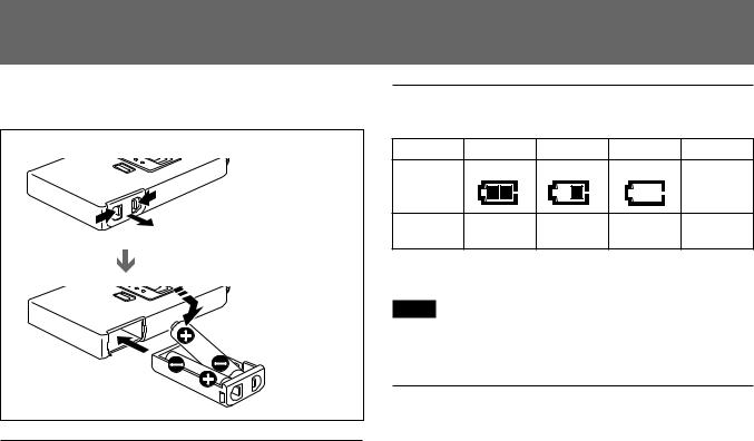
Installing the batteries
1 Slide the battery-holder catches inward (in the direction of the arrows b B) to take out the battery holder.
2 Match the polarities and insert the batteries.
3 Set the battery holder in the original position.
Battery indication
When you turn the power on, the battery status appears in the BATT indication on the display section.
|
1 |
2 |
3 |
4 |
|
BATT |
Lights |
Lights |
Flashes |
Goes off |
|
|
|
|
|
||
indication |
|
|
|
|
|
Battery |
Good |
Less than |
Almost |
Completely |
|
condition |
half-charge |
exhausted |
exhausted |
||
|
When the batteries reach stage 3 shown in the table, the battery indication on the tuner also starts flashing.
Note
The indication may be incorrect if the batteries are not new when installed. If you plan to use the transmitter for a long period, it is best to replace the batteries with new ones.
Notes on batteries
•Use new alkaline batteries.
•Do not pair different types of batteries.
•Always replace the two batteries together.
•The batteries are not rechargeable.
•Be careful to install the batteries with the correct polarity.
•When not using the transmitter for a long period, remove the batteries to avoid leakage. If the batteries do leak, clean all leakage from the battery holder case and the unit. Leakage left in the holder case and the unit may cause poor battery contact. If there seems to be poor battery contact, consult your Sony dealer.
9US
Connections
Notes on Microphone System Operation
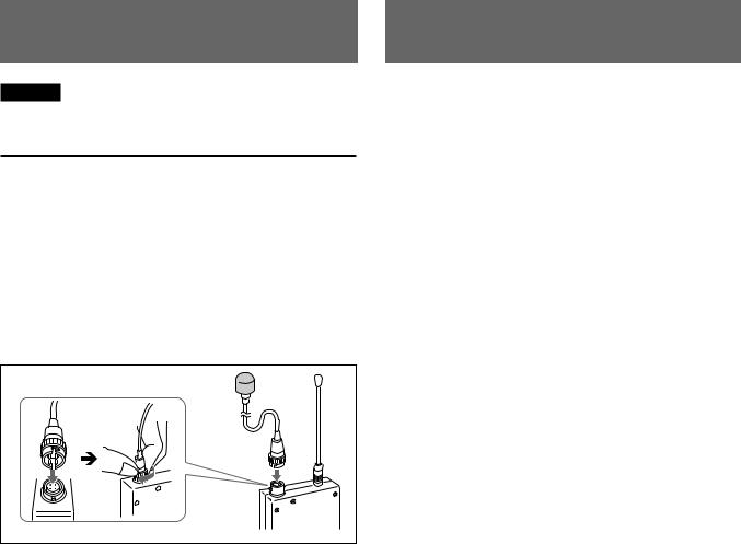
Caution
When connecting a microphone to the unit, be sure to turn the unit off.
To connect a microphone
The WRT-822A accepts the following Sony lavalier microphones:
ECM-44BC ECM-55BC ECM-66BC ECM-77BC ECM-166BC ECM-310BC ECM-350BC
You can also use your wired microphone by connecting it to this connector with an optional EC-1.5CF microphone cable.
To secure the microphone cable connection, be sure to turn and lock the connector cover as illustrated below.
Microphone (not supplied) |
For the input attenuation adjustment, see page 12.
•To operate with two or more channels, maintain a distance of at least 30 cm (one ft.) between each pair of transmitters.
For details of operation with two or more channels, refer to the Operating Instructions for the tuner which is used with the WRT-822A.
•Ensure that the tuners set to channels not being used are either turned off or set to the minimum output level.
•When powering the transmitter on or off, to keep the noise to a minimum, set the audio output level from the tuner or mixer to a minimum.
•Powering the transmitter on without checking the channel selection first may interfere with the operation of other microphones/transmitters, if the current setting is already being used.
•To prevent noise generation, keep the transmitters at least 3 m (10 feet) away from the antennas when the system is operated using a group which allows selection of up to 11 channels, and at least 6 m (20 feet) away when using a group which allows selection of 12 channels.
10US

Settings
Initiating Setting Mode
In Setting mode, you can change the transmission channel/ frequency and the attenuation level, or reset the accumulated time indication.
To enter Setting mode
While holding down the SET button, set the POWER switch to ON.
The transmitter enters Setting mode and the indication before the transmitter was previously turned OFF flashes on the display section.
Each time you press the SET button, the setting items are cyclically switched as shown below.
Channel selection |
Frequency selection |
Accumulated time |
Attenuator adjustment |
indication reset |
|
|
Display example for U68 model |
Changing the Transmitting Channel
1 Confirm that the channel number flashes on the display. If not, set the unit in Setting mode, and press the SET button so that the channel number flashes.
If you want to change the channel in frequency indication, press the SET button one more.
In channel selection mode
In frequency selection mode
Display example for U68 model
2 Press the + or – button to select the channel. Pressing the + button cyclically changes the channel indication in the order shown on pages L-1 to L-3. Pressing the – button changes it in reversed order. If you keep either button pressed, the channel number will be incremented or decremented successively.
Display example for U68 model
11US
Settings
3 Once the desired channel number appears, set the POWER switch to OFF to release Setting mode.
Or, press the SET button to continue operations in Setting mode.
The next time you turn on the power only by setting the POWER switch to ON, the transmitter will be set to Transmit mode with the selected channel.
Notes
•The unit cannot transmit in Setting mode.
•Make sure that the channel selected is the same as that selected on the tuner used in the same system.
•Depending on the noise or interference conditions, the selectable channels may not necessarily all be usable. If necessary, you can determine the usable channels by stepping the channel selection through a number of channels on the tuner with the microphone/transmitter set to OFF. Those channels on which the RF indicator of the tuner does not light are usable.
•If there is a TV broadcasting station near by, do not use the station's channel.
•The unit may not operate correctly if it is turned on again immediately after turning off the power while in setting mode. Pause for a few seconds or more before turning on the power again.
•When operating two or more UHF wireless microphone
systems using channels in different groups, ensure that the systems are at least 100 m (330 feet) apart from each other. (The same applies also when using channels in a group if the different UHF wireless microphone systems are installed where they are within sight of each other.)
Changing the Input Attenuation Setting
You can change the input attenuation setting in 3-dB steps in a range of 0 to 21 dB. You can change it either in Setting mode or in Transmit mode.
Changing in Setting mode
1 Set the unit in Setting mode.
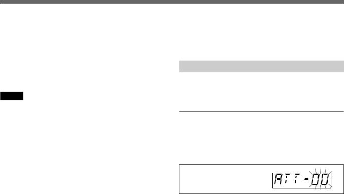
2 Press the SET button until the attenuation level indication appears on the display.
Attenuation level indication
3 Press the + or – button to select the attenuation level.
If you keep either button pressed, the level will be incremented or decremented successively.
12US
4 Once the desired level appears, set the POWER switch to OFF to release Setting mode.
Or, press the SET button to continue operations in Setting mode.
The next time you turn on the power only by setting the POWER switch to ON, the transmitter will be set to Transmit mode with the selected attenuation setting.
Changing in Transmit mode
You can also change the input attenuation level during transmission.
1 If the attenuation level is not displayed, press the SET button until the attenuation level indication appears on the display.
2 Press the + or – button to select the level.
Resetting the Accumulated Time Indication
The time indication accumulates time in hours and minutes when the WRT-822A is on.
Reset the indication to “00:00” whenever you replace the batteries so that it can display the running time of the batteries.
1 Set the unit in Setting mode.
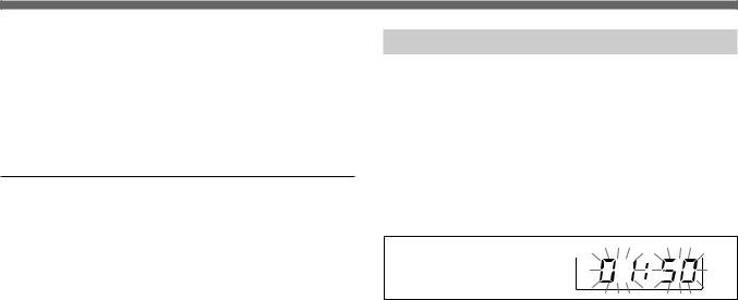
2 Press the SET button until the accumulated time indication appears on the display.
Accumulated time indication
3 Press the – button.
The time indication resets to “00:00.”
While you see “00:00” indication, you can go back to previous value by pressing the + button.
4 Set the POWER switch to OFF to release Setting mode.
13US

Error Messages
When a problem occurs, one of the following error messages may appear on the display.
Messages |
Contents |
Measures |
|
|
|
|
|
Error 11 |
An error occurred in backup memory data. |
The data was initialized. Set the transmitting channel and |
|
the input attenuation again. |
|||
|
|
||
|
|
|
|
Error 21 |
The PLL synthesized circuit is in trouble. |
Contact your Sony dealer. |
|
|
|
|
|
Error 31 |
The battery voltage exceeds the allowable value. |
Use the specified batteries. |
|
|
|
|
|
Error 41 |
Defect of an internal circuit |
|
|
|
|
|
|
Error 51 |
Defect of the A/D converter |
Contact your Sony dealer. |
|
|
|
|
|
Error 61 |
Defect of an internal circuit |
|
|
|
|
|
14US

Specifications
Transmitter and modulator section
Oscillator |
Crystal controlled PLL synthesizer |
Type of emission |
F3E |
Carrier frequencies |
|
U64 model: |
770.125 to 781.875 MHz |
U66 model: |
782.125 to 793.875 MHz |
U68 model: |
794.125 to 805.875 MHz |
RF power output |
10 mW |
Frequency stability |
Within ±0.005% |
Tone signal |
32.768 kHz |
Type of antenna |
1/4 -wavelength wire |
Pre-emphasis |
50 µs |
Deviation |
1) |
±5 kHz (–60 dBV , 1 kHz input |
|
|
with 0 dB audio attenuation) |
Frequency response |
70 to 13,000 Hz |
Signal-to-noise ratio |
60 dB or more |
|
(A-weighted, with reference |
|
deviation at WRR-800A/801A/ |
|
805A/ 810A/820A/840A/850A/ |
|
855A/860A) |
Audio attenuator |
0 to 21 dB, variable in 3-dB steps |
Power section |
|
Power requirements |
3.0 V DC |
|
(two LR6/size AA alkaline |
|
batteries) |
Battery life |
Approx. 8 hours at 25°C (77°F) |
|
with Sony LR6 alkaline batteries |
General |
|
Operating temperature |
0°C to +50°C (32°F to 122°F) |
Storage temperature |
–30°C to +60°C (–22°F to +140°F) |
Dimensions |
63 × 103 × 17 mm (w/h/d) |
|
(21/2 × 41/8 × 11/16 inches) |
Mass |
Approx. 145 g (5.1 oz) including |
|
batteries |
Supplied accessories
Operating Instructions (1)
Soft case (1)
Optional accessories
Lavalier microphones
ECM-44BC, ECM-55BC, ECM-66BC, ECM-77BC, ECM-166BC, ECM-310BC, ECM-350BC
Microphone cable EC-1.5CF
Design and specifications are subject to change without notice.
. . . . . . . . . . . . . . . . . . . . . . . . . . . . . . . . . . . . . . . . . . . . . . . . . . . . . . . . . . . . . . . . . . . . . . . . . . . . . . . . . . . . . . . . . . . . . . . . . . . . . . . . . . . . . . . . . . . . . . . . . . . . . . .
1) 0 dBV = 1 Vrms
15US
 Loading...