


2-688-078-12(1)
Integrated
Stereo Amplifier
Operating Instructions |
GB |
|
|
Manual de instrucciones |
ES |
|
|
Bruksanvisning |
SE |
|
|
|
PL |
|
TA-FA1200ES
Sony Corporation Printed in Malaysia |
|
©2006 Sony Corporation |
WARNING
To reduce the risk of fire or electric shock, do not expose this apparatus to rain or moisture.
To prevent fire, do not cover the ventilation of the apparatus with news papers, table-cloths, curtains, etc. And don’t place lighted candles on the apparatus.
To prevent fire or shock hazard, do not place objects filled with liquids, such as vases, on the apparatus.
Do not install the appliance in a confined space, such as a bookcase or built-in cabinet.
Install this system so that the power cord can be unplugged from the wall socket immediately in the event of trouble.
Don’t throw away the battery with general house waste, dispose of it correctly as chemical waste.
NOTICE FOR THE CUSTOMERS IN THE UNITED KINGDOM
A moulded plug complying with BS1363 is fitted to this equipment for your safety and convenience. Should the fuse in the plug supplied need to be replaced, a fuse of the same rating as the supplied one and approved by ASTA or BSI to BS1362, (i.e., marked with  or
or  mark) must be used.
If the plug supplied with this equipment has a detachable fuse cover, be sure to attach the fuse cover after you change the fuse. Never use the plug without the fuse cover.
If you should lose the fuse cover, please contact your nearest Sony service station.
For customers in Europe
Disposal of Old Electrical & Electronic Equipment (Applicable in the European Union and other European countries with separate collection systems)
This symbol on the product or on its packaging indicates that this product shall not be treated as household waste. Instead it shall be handed over to the applicable collection point for the recycling of electrical and electronic equipment. By ensuring this product is disposed of correctly, you will help prevent potential negative consequences for the environment and human health, which could otherwise be caused by inappropriate waste handling of this product. The recycling of materials will help to conserve natural resources. For more detailed information about recycling of this product, please contact your local Civic Office, your household waste disposal service or the shop where you purchased the product.
2GB

About this manual
•The instructions in this manual are for model TAFA1200ES. Check your model number by looking at the lower right corner of the front panel.
•The instructions in this manual describe the controls on the supplied remote. You can also use the controls on the amplifier if they have the same or similar names as those on the remote.
This amplifier incorporates Dolby* Digital and DTS**.
*Manufactured under license from Dolby Laboratories.
“Dolby” and the double-D symbol are trademarks of Dolby Laboratories.
**“DTS” and “DTS 2.0” are trademarks of Digital Theater Systems, Inc.
Table of contents |
|
Getting Started |
|
Unpacking .................................................... |
4 |
Connecting speakers ..................................... |
4 |
Using a bi-wiring connection ....................... |
6 |
Connecting components with analog audio |
|
input/output jacks .................................... |
7 |
Connecting components with digital audio |
|
input/output jacks .................................... |
8 |
Connecting the AC power cord |
|
(mains lead) ............................................. |
9 |
Inserting batteries into the remote ................ |
9 |
Location of Parts and |
|
Operation |
GB |
Front panel .................................................. |
10 |
Rear panel ................................................... |
11 |
Remote commander .................................... |
12 |
Configuration |
|
Calibrating the appropriate settings |
|
automatically |
|
(AUTO CALIBRATION) ...................... |
13 |
Settings for the amplifier ............................ |
16 |
Clearing the amplifier’s memory ................ |
18 |
Additional Information |
|
Precautions ................................................. |
19 |
Troubleshooting .......................................... |
20 |
Specifications ............................................. |
22 |
Index ........................................................... |
23 |
3GB

Getting Started
Unpacking
Check that you received the following items:
•Operating Instructions (this manual)
•Optimizer microphone ECM-AC1 (1)
•AC power cord (mains lead) (1)
•Remote commander RM-AAU010 (1)
•R6 (size-AA) batteries (2)
If any item is missing, please consult your nearest Sony dealer.
Audio connecting cords, digital connecting cords, speaker cords are not supplied with this amplifier. Please purchase them separately.
Notes on connections
•Turn off the power to all components before making any connections.
•Do not connect the AC power cord (mains lead) until all of the connections are completed.
•Be sure to insert all plugs firmly to avoid hum and noise.
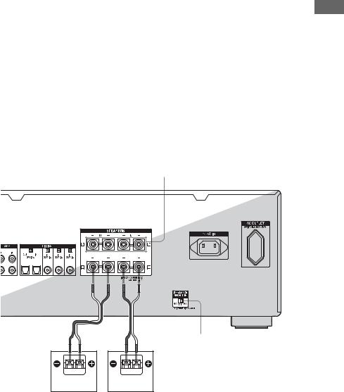
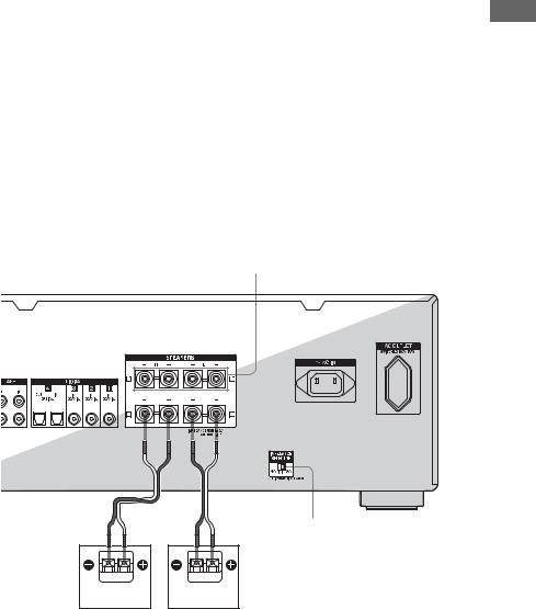
Connecting speakers
Connect your speakers to the amplifier.
Use a speaker cord (not supplied) to connect to the speaker terminals.
Speaker cord (not supplied)
Notes on speaker connections
Connect the left speaker to the SPEAKERS L terminal and the right speaker to the SPEAKERS R terminal.
Be sure to connect the speaker cords between the speakers and the amplifier with the same polarities (plus (+) to plus (+), minus (–) to minus (–)).
By paying attention to the color or mark of the speaker cord to be connected to the plus (+) or minus (–) connector, you can always be sure of connecting the cord correctly without mistaking plus or minus.
4GB
Setting the speaker impedance
•Be sure to turn the power off before adjusting the IMPEDANCE SELECTOR.
•When you connect all speakers with a
nominal impedance of 8 ohms, set the IMPEDANCE SELECTOR to “8Ω.” When
connecting other types of speakers, set it to “4Ω.”
•When you connect speakers to both the SPEAKERS A and B terminals, connect the speakers with a nominal impedance of 8 ohms or higher.
–When you connect speakers with impedance of 16 ohms or higher in both
“A” and “B” configuration:
Set IMPEDANCE SELECTOR to “8Ω.”
–For other types of speakers in other
configurations:
Set IMPEDANCE SELECTOR to “4Ω.”
•If you are not sure of the impedances of the speakers, refer to the operating instructions supplied with your speakers. (This information is often on the back of the speaker.)
SPEAKERS B terminals*
IMPEDANCE SELECTOR
Speaker A Speaker A
(R)(L)
*If you have an additional speaker system, connect them to the SPEAKERS B terminals. You can select the speaker system you want to use with the SPEAKERS (OFF/A/B/A+B) on the front panel (page 11).
Started Getting
5GB
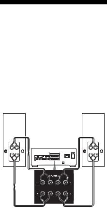
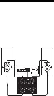
Using a bi-wiring connection
You can make a bi-wiring connection by connecting both the SPEAKERS A terminals and SPEAKERS B terminals simultaneously. When using a bi-wiring connection, set SPEAKERS (OFF/A/B/A+B) to A+B
(page 11).
To connect speakers
Speaker |
Speaker |
(R) |
(L) |
Hi |
Hi |
Lo |
Lo |
Connect the terminals on the Lo (or Hi) side of the speakers to the SPEAKERS A terminals, and connect the terminals on the Hi (or Lo) side of the speakers to the SPEAKERS B terminals. Make sure that metal fittings of Hi/ Lo attached to the speakers have been removed from the speakers. Not doing so may cause a malfunction of the amplifier.
Note
When you use the auto calibration function, make the bi-wiring connection before you perform auto calibration.
6GB

Connecting components with analog audio input/ output jacks
You can connect a component with analog audio jacks, such as a Super Audio CD player or CD player, etc. to this amplifier.
Use an audio cord (not supplied) to connect a component to the analog audio jacks. Connect the white plug to the L jack and the red plug to the R jack.
Audio cord (not supplied)
Started Getting
Turntable |
|
|
Super Audio CD |
|
|
player, |
Tape deck |
|
CD player, |
||
|
||
VCR |
|
Note
If your turntable has a ground (earth) wire, connect it to the (U) SIGNAL GND terminal.
7GB
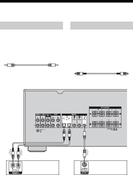
Connecting components with digital audio input/output jacks
Connecting to the COAXIAL jack
You can connect a component with coaxial digital output jacks to this amplifier.
Use a coaxial digital cord (not supplied) to connect a component to the coaxial jacks (DIGITAL 1 to 3).
Coaxial digital cord (not supplied)
Connecting to the OPTICAL jack
You can connect a component with optical digital output jacks to this amplifier.
Use an optical digital cord (not supplied) to connect a component to the optical jacks (DIGITAL 4).
When connecting optical digital cords, insert the plugs straight in until they click into place.
Optical digital cord (not supplied)
MD deck, DAT deck, Satellite tuner
(for the IN jack only)
Super Audio CD player, CD player,
DVD player, DVD recorder
Note |
Tip |
When DIGITAL 1, 2, or 3 is selected, the selected |
All the digital audio jacks are compatible with 32 |
input signal is output from the DIGITAL 4 OUT |
kHz, 44.1 kHz, 48 kHz, and 96 kHz sampling |
jack. When DIGITAL 4 or analog input is selected, |
frequencies. |
no signal is output from the DIGITAL 4 OUT jack. |
|
8GB
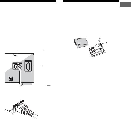
Connecting the AC power cord (mains lead)
Connect the supplied AC power cord (mains lead) to the AC IN terminal on the amplifier, then connect the AC power cord (mains lead) to a wall outlet.
You can connect the AC power cord (mains lead) of your component to the amplifier’s AC OUTLET(s).
AC IN terminal |
AC OUTLET* |
|||
|
|
|
|
|
|
|
|
|
|
|
|
|
|
|
|
|
|
|
|
To the wall outlet
*The configuration, shape, and number of AC outlets will vary according to the area.
AC power cord (mains lead) (supplied)
**
**A several space is left between the plug and the rear panel even when the power cord (mains lead) is inserted firmly. The cord is supposed be connected this way. This is not a malfunction.
Notes
•The AC OUTLET(s) on the rear of the amplifier is a switched outlet, which supplies power to the connected component only while the amplifier is turned on.
•Make sure that the total power consumption of the component(s) connected to the amplifier’s AC OUTLET(s) does not exceed the wattage stated on the rear panel. Do not connect high-wattage electrical home appliances such as electric irons, fans, or TVs to this outlet. This may cause a malfunction.
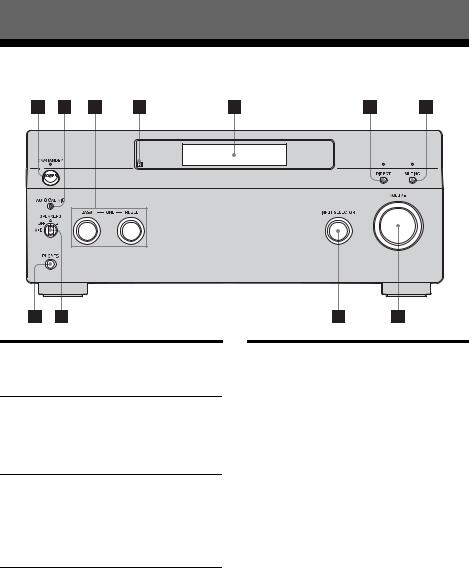
Inserting batteries into
the remote |
Getting |
|
|
||
Insert two R6 (size-AA) batteries in the RM- |
Started |
|
AAU010 remote commander. |
||
|
||
Observe the correct polarity when installing |
|
|
batteries. |
|
RM-AAU010
Notes
•Do not leave the remote in an extremely hot or humid place.
•Do not use a new battery with old ones.
•Do not mix manganese batteries and other kinds of batteries.
•Do not expose the remote sensor to direct sunlight or lighting apparatuses. Doing so may cause a malfunction.
•If you do not intend to use the remote for an extended period of time, remove the batteries to avoid possible damage from battery leakage and corrosion.
Tip
When the remote no longer operates the amplifier, replace all the batteries with new ones.
9GB
Location of Parts and Operation
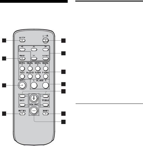
Front panel
Name |
Function |
APOWER |
Press to turn the |
|
amplifier on or off. |
BAUTO CAL MIC Connects to the jack supplied optimizer
microphone for the Auto Calibration function (page 13).
CTONE Turn to adjust the BASS/TREBLE BASS and TREBLE
levels.
The level can be adjusted from –10 dB to +10 dB.
DRemote sensor Receives signals from
|
the remote. |
EDisplay |
The current status of |
|
the selected component |
|
or a list of selectable |
|
items appears here. |
|
|
Name |
Function |
FDIRECT |
Press to bypass the |
|
TONE function to |
|
listen to better quality |
|
sound. |
|
Note |
|
When you play back a DTS |
|
96/24 format disc, set the |
|
DIRECT function to ON. |
|
If the DIRECT function is set |
|
to OFF, the DTS signal is |
|
played back at 48 kHz. |
|
|
GMUTING |
Press to activate the |
|
muting function. |
|
|
HPHONES jack |
Connects to |
|
headphones. |
|
Note |
|
When you connect |
|
headphones, the DTS 96/24 |
|
signal is played back at DTS |
|
48 kHz. |
|
|
10GB
Name |
Function |
|
Name |
Function |
ISPEAKERS |
Turn to select OFF, A, |
|
KVOLUME |
Turn to adjust the |
(OFF/A/B/A+B) |
B, A+B of the speakers. |
|
|
volume level of |
|
|
|
|
speakers. The level can |
JINPUT |
Turn to select the input |
|
|
|
|
|
be adjusted from –∞ dB |
||
SELECTOR |
source to play back. |
|
|
|
|
|
to +23 dB. |
||
|
|
|
|
|
|
|
|
|
|
|
|
|
|
|
|
|
|
|
|
|
|
|
|
|
Rear panel
Operation and Parts of Location
AAUDIO INPUT/OUTPUT section
L |
AUDIO IN/ |
Connects to a Super |
|
OUT jacks |
Audio CD player, |
||
|
|||
R |
|
tape deck, MD deck |
|
|
|
or DAT player, etc |
|
|
|
(page 7). |
BDIGITAL INPUT/OUTPUT section
COAXIAL IN jacks
OPTICAL IN/ OUT jack
Connects to a DVD player, Super Audio CD player, etc. The COAXIAL jacks provide a better quality sound (page 8).
CSPEAKERS section
Connects to speakers (page 4).
DIMPEDANCE SELECTOR
Set the appropriate speaker impedance for the speakers you are using (page 5).
11GB
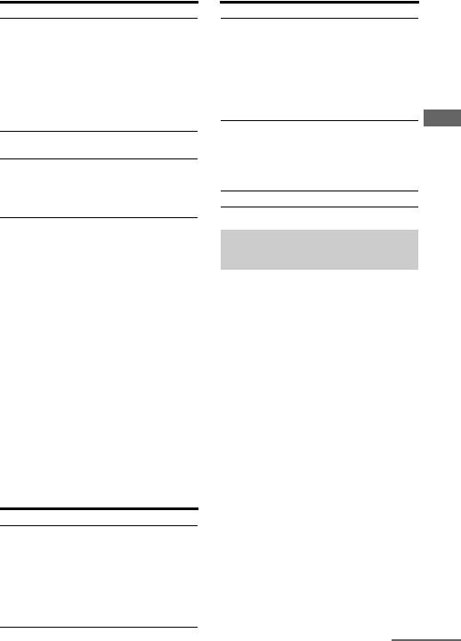
Remote commander
RM-AAU010
Name |
Function |
A ?/1 |
Press to turn the amplifier on or |
(on/standby) |
off. |
|
|
B U/u/I/i |
After pressing MENU (9), |
ENTER |
press U/u, I or i to select the |
|
settings. Then press ENTER to |
|
enter the selection (page 16). |
|
|
C Input |
Press one of the buttons to |
buttons |
select the component you want |
|
to use. When you press any of |
|
the input buttons, the amplifier |
|
turns on. |
|
|
D BALANCE |
Press to adjust the balance |
L/R |
between left and right speakers. |
|
Both the left and the right |
|
balance can be adjusted from 0 |
|
dB to +20 dB. The initial setting |
|
is 0 dB (center). |
|
|
E BASS/ |
Press to adjust the BASS and |
TREBLE +/– |
TREBLE levels. The level can |
|
be adjusted from –10 dB to +10 |
|
dB. |
|
|
F DIMMER |
Press to adjust brightness of the |
|
display. |
G VOLUME +/– Press to adjust the volume level
|
of speakers. |
|
The level can be adjusted from |
|
–∞ dB to +23 dB. |
H SLEEP |
Press to activate the Sleep |
|
Timer function and the duration |
|
which the amplifier turns off |
|
automatically. |
|
The Sleep Timer can be set to |
|
30, 60, 90, or 120 minutes. |
|
|
I MENU |
Press to display the menu for |
|
the amplifier (page 16). |
|
|
J DIRECT |
Press to bypass the TONE |
|
function to listen to better |
|
quality sound. |
|
Note |
|
When you play back a DTS 96/24 |
|
format disc, set the DIRECT |
|
function to ON. |
|
If the DIRECT function is set to |
|
OFF, the DTS signal is played back |
|
at 48 kHz. |
|
|
K MUTING |
Press to activate the muting |
|
function. |
|
|
12GB

Configuration
Calibrating the appropriate settings automatically (AUTO
CALIBRATION)
The auto calibration function allows you to measure the following:
•Whether or not speakers are connected
•Polarity of speakers
•Distance of each speaker from your listening position
•Speaker angle
•Speaker level
•Frequency characteristics
After saving the measurement result, you can confirm the speaker level by pressing BALANCE L/R (page 12). The other measurement results are not displayed, but are set to appropriate settings automatically.
Before you perform auto calibration
Before you perform the auto calibration, set up and connect the speakers (page 4).
•The AUTO CAL MIC jack is used for the supplied optimizer microphone only. Do not connect other microphones to this jack. Doing so may damage the amplifier and the microphone.
•During the calibration, the sound that comes out of the speakers is very loud. The volume of the sound cannot be adjusted. Pay attention to the presence of children or to the effect on your neighborhood.
•Perform the auto calibration in a quiet environment to avoid the effect of noise and get a more accurate measurement.
•If there are any obstacles in the path between the optimizer microphone and the speakers, the calibration cannot be performed
correctly. Remove any obstacles from the measurement area to avoid measurement error.
Notes
•The auto calibration function does not work when headphones are connected to the amplifier.
•Cancel MUTING if it is set to on.
Optimizer microphone (supplied)
Configuration
1 Connect the supplied optimizer microphone to the AUTO CAL MIC jack on the front panel.
2 Set up the optimizer microphone.
Place the optimizer microphone at your listening position. Use a stool or tripod so that the optimizer microphone remains at the same height as your ears. Orient the L end of the optimizer microphone toward the front left speaker and the R end of the optimizer microphone toward the front right speaker.
Performing auto calibration
1 Turn on the amplifier.
2 Press MENU.
continued
13GB

3 Press u to display “<2-Auto
Calibration>,” then press ENTER to enter the menu.
4 Press u to display “CAL TYPE,” then press ENTER to enter the parameter.
5 Press U/u to select the parameter, then press ENTER to enter the selection.
Calibration |
Explanation |
type |
|
|
|
ENGINEER |
Sets the frequency |
|
characteristics to a set that |
|
matches that of the Sony |
|
listening room standard. |
|
|
FULL FLAT |
Makes the measurement of |
|
frequency from each |
|
speaker flat. |
6 Press U to display “AUTO CAL
START?,” then press ENTER to start the measurement.
Measurement starts in five seconds. A countdown appears on the display.
While the time is counting down, stand away from the measurement area to avoid measurement error.
7 Measurement starts.
The measurement process will take approximately 10 seconds. Wait until the measurement process completes.
Tip
When special speakers, such as dipole speakers, are used, the measurements may not be performed correctly or auto calibration cannot be performed.
To cancel auto calibration
Auto calibration is cancelled when you change the volume, change the input source, change the speaker selection, press MUTING, or connect headphones.
Confirming/saving the measurement results
1 Confirm the measurement result.
When the measurement ends, a beep sounds and the measurement result appears on the display.
Measurement Display |
Explanation |
|
result |
|
|
|
|
|
When the |
COMPLETE |
Proceed to step |
measurement |
|
2. |
process |
|
|
completes |
|
|
properly |
|
|
|
|
|
When the |
ERROR |
See “When |
measurement |
CODE XX |
error codes |
process fails |
|
appear” (page |
|
|
14). |
2 Press U/u repeatedly to select the item, then press ENTER.
Item |
Explanation |
RETRY |
Re-performs the auto |
|
calibration. |
|
|
SAVE EXIT |
Saves the measurement |
|
results and exits the setting |
|
process. |
|
|
WRN CHECK |
Displays a warning |
|
concerning the |
|
measurement results. See |
|
“When you select “WRN |
|
CHECK”” (page 15). |
|
|
EXIT |
Exits the setting process |
|
without saving the |
|
measurement results. |
|
|
When error codes appear
Try the remedies and re-perform the auto calibration.
Error code Cause and remedies
CODE 31 SPEAKERS (OFF/A/B/A+B) is set to OFF. Select A or B and reperform the auto calibration.
When using a bi-wiring connection, set SPEAKERS (OFF/A/B/A+B) to A+B.
14GB
Error code |
Cause and remedies |
CODE 32 None of the speakers were detected. Make sure that the optimizer microphone is connected properly and reperform the auto calibration. If the optimizer microphone is connected properly but the error code appears, the optimizer
microphone cable may be damaged or improperly connected.
CODE 33 None of the speakers are connected.
CODE 34 Speakers are not placed in the proper position. Speakers or an optimizer microphone on the right or left may be placed wrongly. Check the speaker position.
•CODE 31
1Turn SPEAKERS (OFF/A/B/A+B) to select A or B, then follow the instructions given in step 2 of “Performing auto calibration.”
When using a bi-wiring connection, set SPEAKERS (OFF/A/B/A+B) to A+B.
•CODE 32, 33, 34
1Remedy the error.
2Press ENTER.
“RETRY?” appears.
3Press U/u to select “YES,” then press ENTER.
The auto calibration is restarted from step 7 of “Performing auto calibration.”
When you select “WRN CHECK”
If a warning on the measurement result is present, detailed information is displayed.
Press ENTER to return to step 1 of “Confirming/saving the measurement results.”
Warning code Explanation
WARNING 40 Try to perform the auto calibration in a quiet environment.
The auto calibration has completed. However, the noise level is high. You may be able to perform the auto calibration properly if you try it again, even though the measurement cannot be performed in all environments.
Warning code Explanation
WARNING 41 Try to perform the auto calibration when the environment is quiet enough to allow proper measurement.
The sound input from the optimizer microphone is outside the acceptable range. It is louder than the loudest sound that can be measured.
WARNING 42 Try to perform the auto calibration when the environment is quiet enough to allow proper measurement.
The volume of the amplifier is out of the acceptable range.
NO WARNING There is no warning information.
Auto Calibration menu parameters
The initial setting is underlined.
xAUTO CAL START? (Starts auto calibration)
•MEASUREMENT COUNTDOWN
A time countdown appears on the display from five seconds to one second.
•MEASURING TONE
Appears while TONE is being measured.
•MEASURING T.S.P.
Appears while TSP* is being measured.
•COMPLETE
Appears when the measurement process completes successfully. For details on each message, see “Confirming/saving the
measurement results” (page 14).
• WARNING CODE [ :4x]
Appears if a warning on the measurement result is present. For details on each message, see “Confirming/saving the measurement results” (page 14).
•NO WARNING
There is no warning information.
• ERROR CODE [ :3x]
Appears when the measurement fails. For details on each message, see “Confirming/ saving the measurement results” (page 14).
continued
Configuration
15GB

•RETRY?
Appears to ask you to re-measure or exit without re-measuring when the measurement fails.
•CANCEL
Appears when you cancel auto calibration during the measurement.
*TSP (Time Stretched Pulse)
A TSP signal is a highly precise measuring signal that utilizes impulse energy, measuring a wide band, from low to high, in a short period.
The amount of energy used to measure signals is important to ensure measurement accuracy in a normal indoor environment. Using TSP signals makes it possible to measure signals effectively.
xCAL TYPE (Parameter type)
•ENGINEER
Sets the frequency to one that matches that of the Sony listening room standard.
•FULL FLAT
Makes the measurement of frequency from each speaker flat.
xEQ CURVE EFFECT (Activates/deactivates the EQ curve measurement)
•OFF
Deactivates the EQ curve measurement.
•ON
Activates the EQ curve measurement. After the measurement is completed, this setting is set to ON automatically.
Notes
•DTS 96/24 signals are played back as 48 kHz signals when EQ CURVE EFFECT is set to “ON.” When you play back DTS 96/24 signals, set this item to “OFF” and set the DIRECT function to “ON” (page 10, 12).
•You cannot select this setting before saving the measurement results (factory setting).
Settings for the amplifier
By using the System Settings menus, you can make various adjustments to customize the amplifier.
1 Press MENU.
2 Press U to display “<1-System
Settings>,” then press ENTER to enter the menu.
3 Press U/u repeatedly to display the parameter you want to adjust.
4 Press ENTER to enter the parameter.
5 Press U/u repeatedly to select the setting you want to adjust.
6 Press ENTER to enter.
7 Repeat steps 3 to 6 when you want to make other settings.
To return to the menu one level up
Press I.
To exit the menu
Press MENU.
Note
Some parameters and settings may appear dimmed on the display. This means that they are either unavailable or fixed and unchangeable.
16GB

System Settings menu parameters
The initial setting is underlined.
xDEC. PRIORITY
(Digital audio input decoding priority)
Lets you specify the input mode for the digital signal input to the DIGITAL IN jacks.
•AUTO
Automatically switches the input mode between DTS, Dolby Digital, or PCM.
•PCM
PCM signals are given priority (to prevent interruption when playback starts).
Note
When set to “AUTO” and the sound from the digital audio jacks (for a CD, etc.) is interrupted when playback starts, set to “PCM.”
xDUAL MONO
(Bilingual audio selection)
For a bilingual broadcast, you can select the language you want to listen to. This feature only functions for Dolby Digital sources.
•MAIN/SUB
Sound of the main language will be output through the left speaker, and sound of the sub language will be output through the right speaker simultaneously.
•MAIN
Sound of the main language will be output.
•SUB
Sound of the sub language will be output.
•MAIN+SUB
Mixed sound of both the main and sub languages will be output.
xD.RANGE COMP.
(Dynamic range compressor)
Lets you compress the dynamic range of the soundtrack. This may be useful when you want to watch movies at low volumes late at night. Dynamic range compression is possible with Dolby Digital sources only.
•OFF
The dynamic range is not compressed.
•STD
The dynamic range is compressed as intended by the recording engineer.
•MAX
The dynamic range is compressed dramatically.
Tip
Dynamic range compressor lets you compress the dynamic range of the soundtrack based on the dynamic range information included in the Dolby Digital signal.
“STD” is the standard setting, but it only enacts light compression. Therefore, we recommend using the “MAX” setting. This greatly compresses the dynamic range and lets you view movies late at night at low volumes. Unlike analog limiters, the levels are predetermined and provide a very natural compression.
xDC PHASE L.
(DC Phase Linearizer)
Lets you approximate the low frequency phase characteristics to a traditional analog amplifier.
•OFF
Phase correction is not performed.
•LOW-A, STD-A, HIGH-A, LOW-B, STD- B, HIGH-B
The bandwidth range of the phase correction increases in the order of “LOW,” “STD,” “HIGH.”
“B” parameter phase correction provides more enhanced bass characteristics.
Configuration
17GB
Clearing the amplifier’s memory
1,2 |
|
|
|
|
|
2 |
|
|
|
||||||
|
|
|
|
|
|
|
|
|
|
|
|
|
|
|
|
|
|
|
|
|
|
|
|
|
|
|
|
|
|
|
|
|
|
|
|
|
|
|
|
|
|
|
|
|
|
|
|
|
|
|
|
|
|
|
|
|
|
|
|
|
|
|
|
|
|
|
|
|
|
|
|
|
|
|
|
|
|
|
|
|
|
|
|
|
|
|
|
|
|
|
|
|
|
|
|
|
|
|
|
|
|
|
|
|
|
|
|
|
|
|
|
1 Press POWER to turn off the amplifier.
2 Hold down POWER while pressing DIRECT and MUTING to turn on the amplifier.
After “MEMORY CLEARING...” appears on the display for a while, “MEMORY CLEARED!” appears.
The following items are reset to their initial settings.
•All settings in the System Settings and Auto Calibration menus.
18GB

Additional Information
Precautions
On safety
Should any solid object or liquid fall into the cabinet, unplug the amplifier and have it checked by qualified personnel before operating it any further.
On power sources
•Before operating the amplifier, check that the operating voltage is identical with your local power supply.
The operating voltage is indicated on the nameplate on the back of the amplifier.
•The unit is not disconnected from the AC power source (mains) as long as it is connected to the wall outlet, even if the unit itself has been turned off.
•If you are not going to use the amplifier for a long time, be sure to disconnect the amplifier from the wall outlet. To disconnect the AC power cord (mains lead), grasp the plug itself; never pull the cord.
•The AC power cord (mains lead) must be changed only at a qualified service shop.
On heat buildup
Although the amplifier heats up during operation, this is not a malfunction. If you continuously use this amplifier at a large volume, the cabinet temperature of the top, side and bottom rises considerably. To avoid burning yourself, do not touch the cabinet.
On placement
•Place the amplifier in a location with adequate ventilation to prevent heat buildup and prolong the life of the amplifier.
•Do not place the amplifier near heat sources, or in a place subject to direct sunlight, excessive dust, or mechanical shock.
•Do not place anything on top of the cabinet that might block the ventilation holes and cause malfunctions.
•Do not place the amplifier near equipment such as a television, VCR, or tape deck. (If the amplifier is being used in combination with a television, VCR, or tape deck, and is placed too close to that equipment, noise may result, and picture quality may suffer. This is especially likely when using an indoor antenna (aerial). Therefore, we recommend using an outdoor antenna (aerial).)
On operation
Before connecting other components, be sure to turn off and unplug the amplifier.
On cleaning
Clean the cabinet, panel, and controls with a soft cloth slightly moistened with a mild detergent solution. Do not use any type of abrasive pad, scouring powder, or solvent, such as alcohol or benzine.
If you have any questions or problems concerning your amplifier, please consult your nearest Sony dealer.
Information Additional
19GB

Troubleshooting
If you experience any of the following difficulties while using the amplifier, use this troubleshooting guide to help you remedy the problem. Should any problem persist, consult your nearest Sony dealer.
Audio
There is no sound, no matter which component is selected, or only a very low-level sound is heard.
•Check that the speakers and components are connected securely.
•Check that all speaker cords are connected correctly.
•Check that both the amplifier and all components are turned on.
•Check that VOLUME control is not set at –∞ dB.
•Check that SPEAKERS (OFF/A/B/A+B) is not set to “OFF” (page 11).
•Press MUTING to cancel the muting function.
•Check that you have selected the correct component with INPUT SELECTOR.
•Check that headphones are not connected.
•The protective device on the amplifier has been activated. Turn off the amplifier, eliminate the short-circuit problem, and turn on the power again.
There is no sound from a specific component.
•Check that the component is connected correctly to the audio input jacks for that component.
•Check that the cord(s) used for the connection is (are) fully inserted into the jacks on both the amplifier and the component.
There is no sound from one of the speakers.
•Connect a pair of headphones to the PHONES jack to verify that sound is
output from the headphones. If only one channel is output from the headphones, the component may not be connected to the amplifier correctly. Check that all the cords are fully inserted into the jacks on both the amplifier and the component. If both channels are output from the headphones, the speaker may not be connected to the amplifier correctly. Check the connection of the speaker which is not outputting any sound.
•Make sure you have connected both the L or R jack to an analog component and not just to either the L or R jack. Use a monaural-stereo cable (not supplied).
The left and right sounds are unbalanced or reversed.
•Check that the speakers and components are connected correctly and securely.
•Adjust the balance parameters by pressing BALANCE on the remote.
There is severe hum or noise.
•Check that the speakers and components are connected securely.
•Check that the connecting cords are away from a transformer or motor, and at least 3 m away from a TV set or fluorescent light.
•Move your TV away from the audio components.
•Make sure you have grounded the U SIGNAL GND terminal (only when a turntable is connected).
•The plugs and jacks are dirty. Wipe them with a cloth slightly moistened with alcohol.
Recording cannot be carried out.
•Check that the components are connected correctly (page 7, 8).
•Select the source component using INPUT SELECTOR (page 11, 12).
20GB
Remote control
The remote does not function.
•Point the remote at the remote sensor on the amplifier.
•Remove any obstacles in the path between the remote and the amplifier.
•Replace all the batteries in the remote with new ones, if they are weak.
•Make sure you select the correct input on the remote.
Error messages
If there is a malfunction, the display shows a code of two numbers. You can check the condition of the system by the message. Refer to the following table to solve the problem. If any problem persists, consult your nearest Sony dealer.
CHECK CODE 11
Irregular current is output from the speakers. Turn off the amplifier, check the central core of a speaker cord is not touching the amplifier or other speakers, and turn on again. When using a bi-wiring connection, check that the metal fittings attached to the speakers that are used to short the Hi/Lo terminals have been removed from the speakers.
CHECK CODE 12
The amplifier section is overheated. Check that the ventilation hole is not covered. Turn off the amplifier, leave the amplifier for a while, and turn on the power again. When using a bi-wiring connection, check that the metal fittings attached to the speakers that are used to short the Hi/Lo terminals have been removed from the speakers.
CHECK CODE 13
The power section is overheated. Check that the ventilation hole is not covered. Turn off the amplifier, leave the amplifier for a while, and turn on the power again. When using a bi-wiring connection, check that the metal fittings attached to the speakers that are used to short the Hi/Lo terminals have been removed from the speakers.
CHECK CODE 14
Turn off the amplifier, check the central core of a speaker cord is not touching the amplifier or other speakers.
CHECK CODE 21
Turn off the amplifier and check that the speaker cords are connected correctly, then turn the power on again. When using a biwiring connection, check that the metal fittings attached to the speakers that are used to short the Hi/Lo terminals have been removed from the speakers.
Information Additional
21GB

Specifications
Amplifier section
POWER OUTPUT Rated Power Output*
8 ohms 1 kHz, THD 0.7%:
110 W + 110 W
4 ohms 1 kHz, THD 0.7%:
120 W + 120 W Power requirements 230 V AC, 50/60 Hz
*Measured under the following conditions: Power requirements: 230 V AC, 50/60 Hz
|
(in countries/area in Europe |
|
other than UK) |
|
240 V AC, 50/60 Hz |
|
(in UK and general area) |
Frequency response |
|
|
|
PHONO |
RIAA equalization curve |
|
± 0.5 dB |
|
|
TUNER, SA-CD/CD, |
10 Hz – 40 kHz |
TAPE |
± 3 dB (8 ohms) |
|
|
Inputs (Analog) |
|
|
|
PHONO |
Sensitivity: 2.5 mV |
|
Impedance: 50 kohms |
|
S/N: 86 dB (A, 20 kHz |
|
LPF) |
|
|
TUNER, SA-CD/CD, |
Sensitivity: 150 mV |
TAPE |
Impedance: 50 kohms |
|
S/N: 96 dB (A, 20 kHz |
|
LPF) |
|
|
Output (Analog) |
|
|
|
TAPE |
Voltage: 150 mV |
|
Impedance: 1 kohms |
|
|
Inputs (Digital) |
|
|
|
DIGITAL 1/2/3 |
Impedance: 75 ohms |
|
S/N: 96 dB (A, 20 kHz |
|
LPF) |
|
|
DIGITAL 4 |
S/N: 96 dB |
|
(A, 20 kHz LPF) |
|
|
Output (Digital)
DIGITAL 4 |
S/N: 96 dB |
|
(A, 20 kHz LPF) |
|
|
TONE |
|
|
|
TREBLE |
±10 dB, 1 dB step |
|
|
BASS |
±10 dB, 1 dB step |
|
|
General
Power requirements 230 V AC, 50/60 Hz (in countries/area in Europe other than UK) 240 V AC, 50/60 Hz
(in UK and general area) Power consumption 100 W
Power consumption (during standby mode) 0.5 W
AC outlets |
1 switched, 100 W/0.4 A |
|
MAX (in countries/area in |
|
Europe other than UK) |
Dimensions |
430 × 173 × 428 mm |
|
including projecting parts |
|
and controls |
Mass (Approx.) |
14.0 kg |
Supplied accessories
Operating Instructions (this manual) Optimizer microphone ECM-AC1 (1) AC power cord (mains lead) (1) Remote commander RM-AAU010 (1) R6 (size-AA) batteries (2)
Design and specifications are subject to change without notice.
22GB

Index
Symbols
U SIGNAL GND terminal 7
A
AC power cord 9
Auto Calibration 13
B
BALANCE 12 Bi-wiring connection 6
C
CD player 7, 8
D
DAT deck 8 DIMMER 12 DIRECT 10, 12 Display 10
DVD player/DVD recorder 8
E
Error messages 21
I
IMPEDANCE SELECTOR 5 INPUT SELECTOR 11
M
MD deck 8 Menu
Auto Calibration 15 System Settings 17
MUTING 10, 12
P
PHONES 10
R
Remote 12
Before Use 9
Resetting 18
S
Satellite tuner 8 SLEEP 12 Speakers 4
SPEAKERS (OFF/A/B/A+B) 11 Super Audio CD player 7, 8
T
Tape deck 7
TONE 10
V
VCR 7
VOLUME 11, 12
Information Additional
23GB
ADVERTENCIA
Para evitar incendios o el riesgo de electrocución, no exponga la unidad a la lluvia ni a la humedad.
Para evitar incendios, no cubra la ventilación del aparato con periódicos, manteles, cortinas, etc. No coloque velas encendidas sobre el aparato.
Para evitar el riesgo de incendios o descargas eléctricas, no coloque recipientes con líquidos, como jarrones sobre el aparato.
No instale el aparato en un espacio cerrado, como una estantería para libros o un armario empotrado.
Instale este sistema de forma que el cable de alimentación pueda ser desenchufado de la toma de corriente de la pared inmediatamente en caso de problema.
No tire las pilas con la basura normal del hogar, deshágase de ellas correctamente como desechos químicos.
Atención para los clientes en Europa
Tratamiento de los equipos eléctricos y electrónicos al final de su vida útil (Aplicable en la Unión Europea y en países europeos con sistemas de recogida selectiva de residuos)
Este símbolo en el equipo o el embalaje indica que el presente producto no puede ser tratado como residuos domésticos normales, sino que debe entregarse en el correspondiente punto de recogida de equipos eléctricos y electrónicos. Al asegurarse de que este producto se desecha correctamente, Ud. ayuda a prevenir las consecuencias negativas para el medio ambiente y la salud humana que podrían derivarse de la incorrecta manipulación en el momento de deshacerse de este producto. El reciclaje de materiales ayuda a conservar los recursos naturales. Para recibir información detallada sobre el reciclaje de este producto, póngase en contacto con el ayuntamiento, el punto de recogida más cercano o el establecimiento donde ha adquirido el producto.
2ES

Acerca de este manual
•Las instrucciones de este manual son para el modelo TA-FA1200ES. Compruebe el número de su modelo, mirando en la esquina inferior derecha del panel frontal.
•Las instrucciones de este manual describen los controles del mando a distancia suministrado. También es posible utilizar los controles del amplificador, si presentan los mismos nombres o similares a los del mando a distancia.
Este receptor incorpora Dolby* Digital y DTS**.
*Fabricado bajo licencia de Dolby Laboratories. “Dolby” y el símbolo de la doble D son marcas comerciales de Dolby Laboratories.
**“DTS” y “DTS 2.0” son marcas comerciales de Digital Theater Systems, Inc.
Índice alfabético
Procedimientos iniciales
Desembalaje ................................................. |
4 |
Conexión de los altavoces ............................ |
4 |
Conexión bifilar ............................................ |
6 |
Conexión de componentes con tomas de |
|
entrada/salida para audio analógico ........ |
7 |
Conexión de componentes con tomas de |
|
entrada/salida para audio digital .............. |
8 |
Conexión del cable de alimentación de |
|
CA ........................................................... |
9 |
Inserción de las pilas en el mando a |
|
distancia ................................................... |
9 |
Ubicación de componentes y operación
...............................................Panel frontal |
10 |
ES |
............................................Panel posterior |
11 |
|
Mando a distancia ....................................... |
12 |
|
Configuración
Calibración automática de los ajustes |
|
adecuados |
|
(AUTO CALIBRATION) ...................... |
13 |
Ajustes del amplificador ............................. |
17 |
Borrado de la memoria del amplificador .... |
18 |
Información complementaria
Precauciones ............................................... |
19 |
Solución de problemas ............................... |
20 |
Especificaciones ......................................... |
22 |
Índice .......................................................... |
23 |
3ES

Procedimientos iniciales
Desembalaje
Compruebe que ha recibido los siguientes elementos:
•Manual de instrucciones (este manual)
•Micrófono optimizador ECM-AC1 (1)
•Cable de alimentación de CA (1)
•Mando a distancia RM-AAU010 (1)
•Pilas R6 (tamaño AA) (2)
Si falta algún elemento, consulte con su distribuidor Sony.
Con este amplificador no se suministran cables de conexión de audio, cables de conexión digital, ni cables de altavoz. Deberá adquirirlos por separado.
Notas acerca de las conexiones
•Desconecte la alimentación de todos los componentes antes de realizar las conexiones.
•No conecte el cable de alimentación de CA hasta que haya terminado de realizar todas las conexiones.
•Asegúrese de que inserta bien todos los enchufes, para evitar zumbidos o ruidos.
Conexión de los altavoces
Conecte los altavoces al amplificador. Utilice un altavoz (no suministrado) para conectarlo a los terminales del altavoz.
Cable de altavoz (no suministrado)
Notas acerca de las conexiones de los altavoces
Conecte el altavoz izquierdo al terminal SPEAKERS L y el altavoz derecho al terminal SPEAKERS R.
Asegúrese de conectar los cables de altavoz entre los altavoces y el amplificador con las mismas polaridades (positiva (+) con positiva
(+) y negativa (–) con negativa (–)).
Si presta atención al color o la marca del cable de altavoz que debe conectar al conector positivo (+) o negativo (–), siempre se asegurará de estar conectando el cable correctamente, sin confundirse de polaridad.
4ES
Ajuste de la impedancia del altavoz
•Asegúrese de desconectar la alimentación antes de ajustar el selector IMPEDANCE SELECTOR.
•Cuando conecte todos los altavoces con una
impedancia nominal de 8 ohmios, ajuste el IMPEDANCE SELECTOR en “8 Ω”.
Cuando conecte otros tipos de altavoces, ajústelo en “4 Ω”.
•Cuando conecte altavoces a ambos terminales, A y B, de SPEAKERS, conecte los altavoces con una impedancia nominal de 8 ohmios o superior.
–Cuando conecte altavoces cuya impedancia es de 16 ohmios o superior, tanto en la configuración “A” como en la “B”:
Ajuste el IMPEDANCE SELECTOR a “8 Ω”.
–Para otros tipos de altavoces en otras configuraciones:
Ajuste el IMPEDANCE SELECTOR a “4 Ω”.
•Si no está seguro de las impedancias de los altavoces, consulte las instrucciones que vinieran con sus altavoces. (Esta información suele estar en la parte posterior del altavoz.)
Terminales SPEAKERS B*
IMPEDANCE SELECTOR
Altavoz A |
Altavoz A |
(derecho) |
(izquierdo) |
*Si tiene un sistema de altavoces adicional, conéctelo a los terminales SPEAKERS B. Puede seleccionar el sistema de altavoces que desea utilizar con el control SPEAKERS (OFF/A/B/ A+B) del panel frontal (página 11).
iniciales Procedimientos
5ES
Conexión bifilar
Puede realizar una conexión bifilar si conecta los terminales SPEAKERS A y SPEAKERS B al mismo tiempo. Si utiliza una conexión bifilar, ajuste SPEAKERS (OFF/A/B/A+B) en A+B (página 11).
Para conectar los altavoces
Altavoz |
Altavoz |
(derecho) |
(izquierdo) |
Hi |
Hi |
Lo |
Lo |
Conecte los terminales del lado Lo (o Hi) de los altavoces en los terminales SPEAKERS A y conecte los terminales del lado Hi (o Lo) de los altavoces en los terminales SPEAKERS B. Es importante retirar los accesorios metálicos Hi/Lo colocados en los altavoces. De lo contrario, podría averiarse el amplificador.
Nota
Si utiliza la función de calibración automática, configure los dos cables antes de llevar a cabo la calibración.
6ES
 Loading...