


 Loading...
3-864-981-12(1)
5 Channel
Power Amplifier
Operating Instructions |
US |
Mode d’emploi |
FR |
TA-N9000ES
ã 1998 by Sony Corporation
WARNING
To prevent fire or shock hazard, do not expose the unit to rain or moisture.
To avoid electrical shock, do not open the cabinet. Refer servicing to qualified personnel only.
Do not install the appliance in a confined space, such as a bookcase or built-in cabinet.
For the customers in United States
This symbol is intended to alert the user to the presence of uninsulated “dangerous voltage” within the product’s enclosure that may be of sufficient magnitude to constitute a risk of electric shock to persons.
This symbol is intended to alert the user to the presence of important operating and maintenance (servicing) instructions in the literature accompanying the appliance.
INFORMATION
This equipment has been tested and found to comply with the limits for a Class B digital device, pursuant to Part 15 of the FCC Rules.
These limits are designed to provide reasonable protection against harmful interference in a residential installation. This equipment generates, uses, and can radiate radio frequency energy and, if not installed and used in accordance with the instructions, may cause harmful interference to radio communications.
However, there is no guarantee that interference will not occur in a particular installation. If this equipment does cause harmful interference to radio or television reception, which can be determined by turning the equipment off and on, the user is encouraged to try to correct the interference by one or more of the following measures:
–Reorient or relocate the receiving antenna.
–Increase the separation between the equipment and power amplifier.
–Connect the equipment into an outlet on a circuit different from that to which the power amplifier is connected.
–Consult the dealer or an experienced radio/TV technician for help.
CAUTION
You are cautioned that any changes or modification not expressly approved in this manual could void your authority to operate this equipment.
Owner’s Record
The model and serial numbers are located on the rear of the unit. Record the serial number in the space provided below. Refer to them whenever you call upon your Sony dealer regarding this product.
Model No. TA-N9000ES
Serial No.
For the customers in Canada CAUTION
TO PREVENT ELECTRIC SHOCK, DO NOT USE THIS POLARIZED AC PLUG WITH AN EXTENSION CORD, RECEPTACLE OR OTHER OUTLET UNLESS THE BLADES CAN BE FULLY INSERTED TO PREVENT BLADE EXPOSURE.
2US

About This Manual
The instructions in this manual are for model TA-N9000ES. Check your model number by looking at the lower right corner of the front panel.
Conventions
•The following icon is used in this manual:
zIndicates hints and tips for making the task easier.
TABLE OF CONTENTS
Hooking Up the Components 4
Unpacking 4 |
|
Normal Connections Using One Power |
|
Amplifier |
6 |
Normal Connections Using Two Power |
|
Amplifiers |
7 |
If You Already Have an Integrated Stereo |
|
Amplifier |
8 |
Using the Power Amplifier with a Digital Signal |
|
Processor |
9 |
BTL Connections Using Two Power Amplifiers 10 |
|
Control A1 Connections 11 |
|
Power Connections 11 |
|
|
|
|
|
Location of Parts and Basic |
|
|||
Operations |
12 |
|
|
|
US |
||||
Front Panel Parts Description 12 |
||||
|
||||
|
|
|||
|
|
|
||
Additional Information 14 |
|
|||
Precautions 14 |
|
|
|
|
Troubleshooting |
15 |
|
|
|
Specifications 16
3US

Hooking Up the Components
This chapter describes how to connect a Sony TA-E9000ES control amplifier, your speakers, and your other audio components to the power amplifier. Be sure to read this section before making any connections.
Unpacking
Check that you received the following items:
• Control A1 cable (1)
Before you get started
•Turn off the power to all components before making any connections.
•Do not connect the AC power cords until all of the connections are completed.
•Be sure to make connections firmly to avoid hum and noise.
•When connecting an audio cord, be sure to match the color-coded pins to the appropriate jacks on the components: white (left) to white; and red (right) to red.
•When connecting the center channel, you can use either the red or white pins on the audio cord.
4US
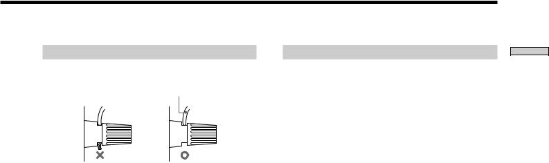
Notes on speaker system hookup
•Twist the stripped ends of the speaker cords about 10 mm.
speaker cord
This is a high output amplifier. Touching the stripped end of the speaker cords may result in injury.
When connecting the speakers, be sure the stripped end of the speakers cord does not protrude from the speaker terminal.
•Connect the right front and rear speakers to the FRONT and REAR SPEAKERS “R” terminals, connect the left front and rear speakers to the FRONT and REAR SPEAKERS “L” terminals.
Be sure to match the speaker cord to the appropriate terminal on the components: + to + and – to –. If the cords are reversed, the sound will be distorted and will lack bass.
•If you use front speakers that have a low maximum input rating, adjust the volume of the control amplifier carefully to avoid producing excessive output from this unit that may be harmful to the speakers.
•To obtain a higher power output when using speakers with a nominal impedance greater than 8 ohms, connect the speakers using BTL connections.
When making BTL connections, refer to “BTL Connections Using Two Power Amplifiers” on page 10 for details.
•Set the SPEAKER IMPEDANCE selector on the rear panel according to the type of speakers you are connecting. See “Selecting the speaker impedance” on this page for details.
•When making normal (non-BTL) connections to your speakers, be sure the OPERATION selector on the rear panel of the power amplifier is set to “NORMAL”.
When making BTL connections, set to “BTL”.
Selecting the speaker impedance
Be sure to set the SPEAKER IMPEDANCE selector on the rear panel of the power amplifier to the top position when making normal connections to speakers with nominal impedance of 4 to 8 ohms, or when making BTL connections to speakers with nominal impedance of 8 to 16 ohms.
Set the SPEAKER IMPEDANCE selector on the rear panel of the power amplifier to the bottom position when making normal connections to speakers with a nominal impedance greater than 8 ohms, or making BTL connections to speakers with a nominal impedance greater than 16 ohms.
Setting the selector to the top position will decrease the power amplifier’s maximum output.
Note
Be sure to the power amplifier is turned off before you change the position of the SPEAKER IMPEDANCE selector.
5US
Components the Up Hooking

Components the Up Hooking
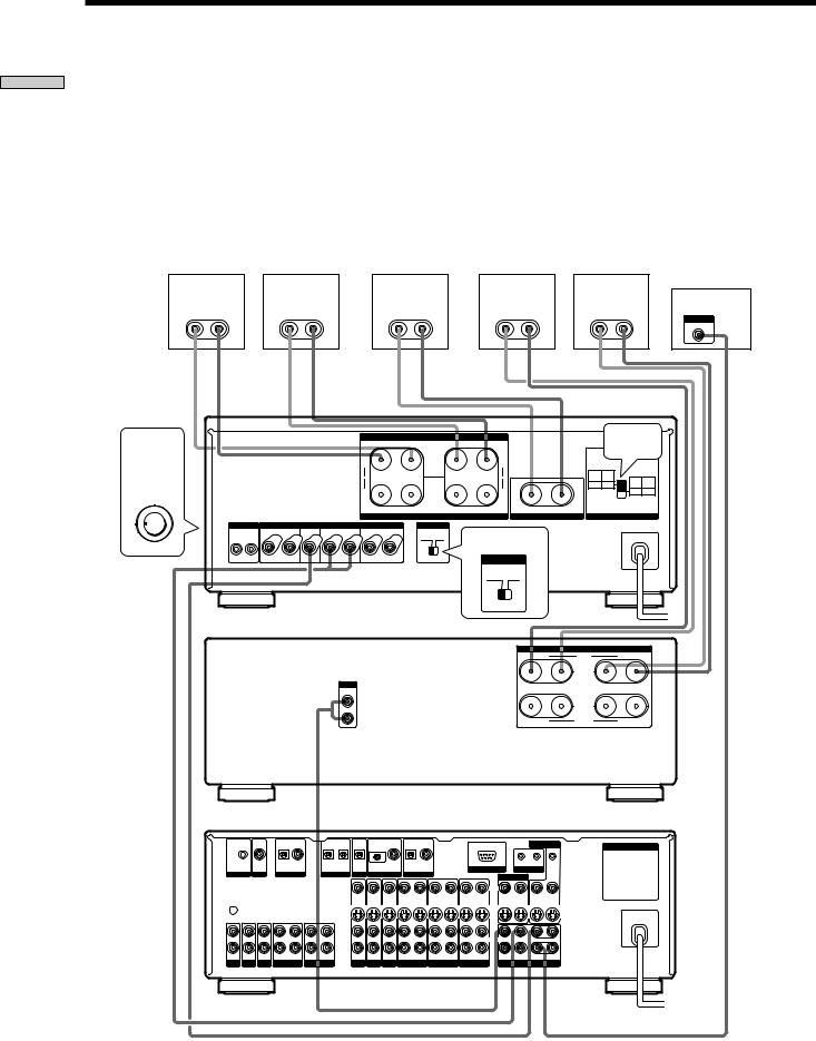
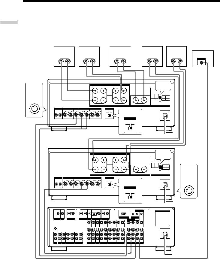
Normal Connections Using One Power Amplifier
Be sure the OPERATION selector on the rear panel is set to NORMAL.
If you have a separate two channel (stereo) amplifier that you would also like to use with the front speakers, connect it to the EXTRA 2 CH INPUT jacks.
|
Right (R) |
|
Left (L) |
|
Right (R) |
|
Left (L) |
Center |
|
|
Rear Speaker |
Rear Speaker |
Front Speaker |
Front Speaker |
Speaker |
|
Active Woofer |
||||
|
|
|
|
|
|
|
|
|
|
INPUT |
} |
] |
} |
] |
} |
] |
} |
] |
} |
] |
AUDIO IN |
|
||||||||||
Set OPERATION to “5ch”
OPERATION
5ch / BTL 2+1 ch |
WARM UP |
EXTRA 2ch / BTL EXTRA 2ch |
|
4ch / BTL 2ch |
|
3ch |
|
2ch |
|
To listen to the stereo control amplifier set OPERATION to
“EXTRA 2ch”
TA-N9000ES
|
|
|
|
+ |
|
FRONT SPEAKERS |
|
+ |
|
|
|
See page 5 |
|||
|
|
|
|
R |
– |
– |
L |
|
|
|
|
|
|
||
|
|
|
|
( + ) |
|
|
|
|
( + ) |
|
|
|
|
|
|
|
|
|
|
BTL |
|
|
|
|
BTL |
|
|
NORMAL |
BTL |
|
|
|
|
|
|
|
|
|
|
|
|
USE |
USE |
NORMAL |
BTL |
||
|
|
|
|
|
|
|
|
|
|
|
|
4Ω MIN |
8Ω MIN |
||
|
|
|
|
|
|
|
|
|
|
|
|
USE |
USE |
||
|
|
|
|
( – ) |
|
|
|
|
( – ) |
|
|
8Ω MIN |
16Ω MIN |
||
|
|
|
|
|
|
|
|
|
|
|
|
|
|
||
|
|
|
|
+ |
R |
– |
– |
L |
+ |
– |
+ |
|
|
|
|
|
|
|
|
|
|
REAR SPEAKERS |
|
|
CENTER SPEAKER |
SPEAKER IMPEDANCE |
|||||
S-LINK |
|
INPUT |
|
|
OPERATION |
|
|
|
|
|
|
|
|
||
CTRL A1 |
REAR |
CENTER |
FRONT |
EXTRA 2CH |
|
|
|
|
|
|
|
|
|
|
|
|
|
|
|
|
|
NORMAL |
BTL |
|
|
|
|
|
|
|
|
|
|
|
|
|
|
|
|
|
Set to NORMAL |
|
|
|
|
|
|
R |
L |
R |
L |
R |
L |
|
|
|
|
|
|
|
|
|
|
OPERATION
NORMAL BTL
Stereo Control |
CD player |
|
Amplifier |
(etc.) |
|
R L |
R L |
R L |
PRE OUT |
INPUT |
OUTPUT |
TA-E9000ES AV Control Amplifier
MIC IN |
AC-3 RF |
OPTICAL COAXIAL |
OPTICAL OPTICAL OPTICAL |
OPTICAL |
COAXIAL OPTICAL COAXIAL |
|
|||||
|
IN |
IN |
IN |
OUT |
IN |
IN |
IN |
IN |
IN |
IN |
|
ANALIZER |
LD |
|
CD |
MD/DAT |
TV/DBS |
DVD |
LD |
|
|
||
|
|
|
|
|
|
IN |
IN |
IN OUT |
IN |
OUT |
IN |
y 
SIGNAL GND
L
R
IN |
IN |
IN |
REC OUT IN |
REC OUT IN |
IN |
IN |
IN |
REC OUT IN |
REC OUT IN |
PHONO |
TUNER |
CD |
MD/DAT |
TAPE |
TV/DBS DVD |
LD |
VIDEO 3 |
VIDEO 2 |
|
|
|
|
|
MONITOR |
AC OUTLET |
|
|
|
|
|
|
|
|
|
|
|
CTRL A1 |
CTRL S |
|
|
|
RS-232C |
S-LINK |
|
|||
|
IN |
|
||||
|
|
PROCESSOR |
|
|
|
|
|
|
VIDEO |
|
|
|
|
OUT |
IN |
OUT |
IN |
OUT |
OUT |
|
|
|
S-VIDEO |
|
|
|
|
|
|
L |
|
|
|
|
|
|
AUDIO |
|
CENTER |
|
|
|
|
R |
|
|
|
|
REC OUT |
IN |
FRONT |
REAR |
WOOFER |
|
|
VIDEO 1 |
|
PRE OUT |
|
|
||
6US

Normal Connections Using Two Power Amplifiers
Use one power amplifier for the front and center speakers, and one for the rear speakers.
Be sure the OPERATION selector on the rear panel is set to NORMAL.
|
Right (R) |
|
Left (L) |
|
Center |
|
Right (R) |
|
Left (L) |
Front Speaker |
Front Speaker |
|
Speaker |
Rear Speaker |
Rear Speaker |
||||
} |
] |
} |
] |
} |
] |
} |
] |
} |
] |
TA-N9000ES
Set |
|
|
|
|
+ |
R |
– |
– |
L |
+ |
|
|
|
See page 5 |
||
|
|
|
|
|
|
|
FRONT SPEAKERS |
|
|
|
|
|
|
|
|
|
OPERATION |
|
|
|
|
|
|
|
|
|
|
|
|
|
|
|
|
to |
|
|
|
( + ) |
|
|
|
|
|
( + ) |
|
|
|
|
|
|
“3ch” |
|
|
|
BTL |
|
|
|
|
|
BTL |
|
|
NORMAL |
BTL |
NORMAL |
BTL |
|
|
|
|
|
|
|
|
|
|
|
USE |
USE |
|
|
||
|
|
|
|
|
|
|
|
|
|
|
|
|
4Ω MIN |
8Ω MIN |
USE |
USE |
|
|
|
|
( – ) |
|
|
|
|
|
( – ) |
|
|
8Ω MIN |
16Ω MIN |
||
OPERATION |
|
|
|
|
|
|
|
|
|
|
|
|
|
|
||
|
|
|
|
|
+ |
R |
– |
– |
L |
+ |
– |
+ |
|
|
|
|
|
|
|
|
|
|
|
REAR SPEAKERS |
|
|
CENTER SPEAKER |
SPEAKER IMPEDANCE |
|||||
3ch |
S-LINK |
|
INPUT |
|
|
OPERATION |
|
|
|
|
|
|
|
|
||
|
CTRL A1 |
REAR |
CENTER |
FRONT |
EXTRA 2CH |
|
|
|
Set to NORMAL |
|
|
|
|
|
||
|
|
|
|
|
|
|
NORMAL |
BTL |
|
|
|
|
|
|
||
|
R |
L |
R |
L |
R |
L |
|
|
|
OPERATION |
|
|
|
|
|
|
|
|
|
|
|
|
|
|
|
|
|
|
|
|
|
||
|
|
|
|
|
|
|
|
|
|
NORMAL |
BTL |
|
|
|
|
|
Active Woofer
INPUT
AUDIO IN
TA-N9000ES
FRONT SPEAKERS |
|
|
See page 5 |
|
|||
+ R – |
– L |
+ |
|
|
|||
|
|
|
|
|
|||
( + ) |
|
( + ) |
|
|
|
|
|
BTL |
|
BTL |
NORMAL |
BTL |
|
|
|
|
USE |
USE |
NORMAL |
BTL |
|
||
( – ) |
|
( – ) |
4Ω MIN |
8Ω MIN |
Set |
||
|
USE |
USE |
|||||
|
|
|
|
|
8Ω MIN |
16Ω MIN |
|
OPERATION
|
|
|
|
|
+ |
R |
– |
– |
L |
+ |
– |
+ |
to |
|
|
|
|
|
|
|
REAR SPEAKERS |
|
|
CENTER SPEAKER |
SPEAKER IMPEDANCE |
||
S-LINK |
|
|
INPUT |
|
|
|
OPERATION |
|
|
|
|
“2ch” |
|
CTRL A1 |
REAR |
CENTER |
FRONT |
|
EXTRA 2CH |
|
|
|
|
|
|
|
|
|
|
|
|
|
|
|
NORMAL |
BTL |
|
Set to NORMAL |
|
OPERATION |
|
|
|
|
|
|
|
|
|
|
|
|
|||
R |
|
L |
R |
L |
R |
L |
|
|
|
OPERATION |
|
|
|
|
|
|
|
|
|
|
|
|
|
|
|
||
|
|
|
|
|
|
|
|
|
|
NORMAL |
BTL |
|
2ch |
|
|
|
|
|
|
|
|
|
|
|
|
|
|
TA-E9000ES AV Control Amplifier
MIC IN |
AC-3 RF |
OPTICAL COAXIAL |
OPTICAL OPTICAL OPTICAL |
OPTICAL |
COAXIAL OPTICAL COAXIAL |
|
|||||
|
IN |
IN |
IN |
OUT |
IN |
IN |
IN |
IN |
IN |
IN |
|
ANALIZER |
LD |
|
CD |
MD/DAT |
TV/DBS |
DVD |
LD |
|
|
||
|
|
|
|
|
|
IN |
IN |
IN OUT |
IN |
OUT |
IN |
y 
SIGNAL GND
L
R
IN |
IN |
IN |
REC OUT IN |
REC OUT IN |
IN |
IN |
IN |
REC OUT IN |
REC OUT IN |
PHONO |
TUNER |
CD |
MD/DAT |
TAPE |
TV/DBS DVD |
LD |
VIDEO 3 |
VIDEO 2 |
|
|
|
|
|
MONITOR |
AC OUTLET |
|
|
|
|
CTRL A1 |
CTRL S |
|
|
|
RS-232C |
S-LINK |
|
|||
|
IN |
|
||||
|
|
PROCESSOR |
|
|
|
|
|
|
VIDEO |
|
|
|
|
OUT |
IN |
OUT |
IN |
OUT |
OUT |
|
|
|
S-VIDEO |
|
|
|
|
|
|
L |
|
|
|
|
|
|
AUDIO |
|
CENTER |
|
|
|
|
R |
|
|
|
|
REC OUT |
IN |
FRONT |
REAR |
WOOFER |
|
|
VIDEO 1 |
|
PRE OUT |
|
|
||
Components the Up Hooking
7US
Components the Up Hooking
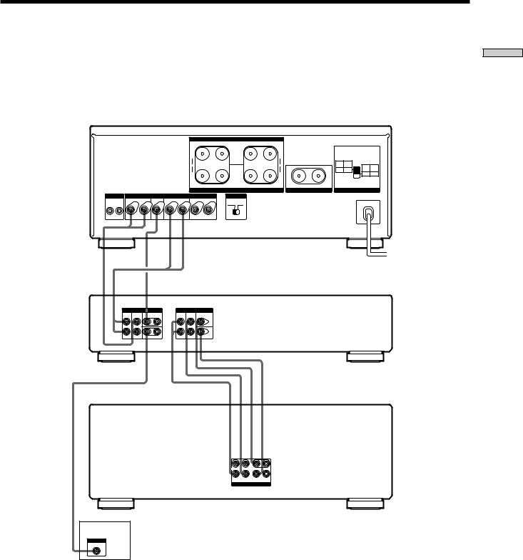
If You Already Have an Integrated Stereo Amplifier
Make the following connections if you would like to use your integrated stereo amplifier to power the front speakers and this unit to power the rear and center speakers.
Be sure the OPERATION selector on the rear panel is set to NORMAL.
Note
Set the volume control on your integrated stereo amplifier to the center position (roughly 12 o’clock). Setting it to the MAX position may produce an audible noise.
|
Right (R) |
|
Left (L) |
Center |
|
|
Right (R) |
|
Left (L) |
Rear Speaker |
Rear Speaker |
Speaker |
|
Front Speaker |
Front Speaker |
||||
} |
] |
} |
] |
} |
] |
} |
] |
} |
] |
Active Woofer
INPUT
AUDIO IN
|
|
|
|
|
|
|
|
|
|
|
|
|
|
TA-N9000ES |
|||
Set |
|
|
|
|
+ |
|
FRONT SPEAKERS |
|
+ |
|
|
|
|
See page 5 |
|||
|
|
|
|
R |
– |
– |
L |
|
|
|
|
||||||
OPERATION |
|
|
|
|
|
|
|
|
|
|
|
|
|
|
|
|
|
to |
|
|
|
|
( + ) |
|
|
|
|
( + ) |
|
|
|
|
|
|
|
“3ch” |
|
|
|
|
|
|
|
|
|
|
|
|
USE |
USE |
|
NORMAL |
BTL |
|
|
|
|
|
BTL |
|
|
|
|
BTL |
|
|
NORMAL |
BTL |
|
|
|
|
|
|
|
|
|
|
|
|
|
|
|
|
|
|
|
||
|
|
|
|
|
|
|
|
|
|
|
|
|
4Ω MIN |
8Ω MIN |
USE |
USE |
|
OPERATION |
|
|
|
|
( – ) |
|
|
|
|
( – ) |
|
|
8Ω MIN |
16Ω MIN |
|||
|
|
|
|
|
|
|
|
|
|
|
|
|
|
|
|||
|
|
|
|
|
+ |
R |
– |
– |
L |
+ |
– |
+ |
|
|
|
|
|
|
|
|
|
|
|
|
REAR SPEAKERS |
|
|
CENTER SPEAKER |
SPEAKER IMPEDANCE |
||||||
3ch |
S-LINK |
|
INPUT |
|
|
OPERATION |
|
|
|
|
|
|
|
|
|
||
|
|
|
|
|
|
|
|
|
|
|
|
|
|||||
|
CTRL A1 |
REAR |
CENTER |
FRONT |
EXTRA 2CH |
|
|
|
|
|
|
|
|
|
|
|
|
|
|
|
|
|
|
|
NORMAL |
BTL |
|
Set to NORMAL |
|
|
|
|
|
|
|
|
|
|
|
|
|
|
|
|
|
|
|
|
|
|
|
||
|
R |
L |
R |
L |
R |
L |
|
|
|
OPERATION |
|
|
|
|
|
|
|
|
|
|
|
|
|
|
|
|
|
NORMAL |
BTL |
|
|
|
|
|
|
Integrated stereo amplifier |
|
R |
MAIN |
L |
|
|
|
SPEAKERS |
|
INPUT |
+ |
– |
– |
+ |
AUX |
||||
L |
|
|
|
|
R |
|
R |
BI-WIRE |
L |
|
|
TA-E9000ES AV Control Amplifier
MIC IN |
AC-3 RF |
OPTICAL COAXIAL |
OPTICAL OPTICAL OPTICAL |
OPTICAL |
COAXIAL OPTICAL COAXIAL |
|
|||||
|
IN |
IN |
IN |
OUT |
IN |
IN |
IN |
IN |
IN |
IN |
|
ANALIZER |
LD |
|
CD |
MD/DAT |
TV/DBS |
DVD |
LD |
|
|
||
|
|
|
|
|
|
IN |
IN |
IN OUT |
IN |
OUT |
IN |
y 
SIGNAL GND
L
R
IN |
IN |
IN |
REC OUT IN |
REC OUT IN |
IN |
IN |
IN |
REC OUT IN |
REC OUT IN |
PHONO |
TUNER |
CD |
MD/DAT |
TAPE |
TV/DBS DVD |
LD |
VIDEO 3 |
VIDEO 2 |
|
|
|
|
|
MONITOR |
AC OUTLET |
|
|
|
|
CTRL A1 |
CTRL S |
|
|
|
RS-232C |
S-LINK |
IN |
|
||
|
|
PROCESSOR |
|
|
|
|
|
|
VIDEO |
|
|
|
|
OUT |
IN |
OUT |
IN |
OUT |
OUT |
|
|
|
S-VIDEO |
|
|
|
|
|
|
L |
|
|
|
|
|
|
AUDIO |
|
CENTER |
|
|
|
|
R |
|
|
|
|
REC OUT |
IN |
FRONT |
REAR |
WOOFER |
|
|
VIDEO 1 |
|
PRE OUT |
|
|
||
8US
Using the Power Amplifier with a Digital Signal Processor
If necessary, you can use more than one power amplifier. For details regarding speaker connections, please refer to other pages.
TA-N9000ES
+ |
|
FRONT SPEAKERS |
|
+ |
|
|
|
|
|
|
|
R |
– |
– |
L |
|
|
|
|
|
|
||
( + ) |
|
|
|
|
( + ) |
|
|
|
|
|
|
BTL |
|
|
|
|
BTL |
|
|
NORMAL |
BTL |
|
|
|
|
|
|
|
|
USE |
USE |
NORMAL |
BTL |
||
|
|
|
|
|
|
|
|
4Ω MIN |
8Ω MIN |
||
|
|
|
|
|
|
|
|
USE |
USE |
||
( – ) |
|
|
|
|
( – ) |
|
|
8Ω MIN |
16Ω MIN |
||
|
|
|
|
|
|
|
|
|
|
||
+ |
R |
– |
– |
L |
+ |
– |
+ |
|
|
|
|
|
|
REAR SPEAKERS |
|
|
CENTER SPEAKER |
SPEAKER IMPEDANCE |
|||||
S-LINK |
|
INPUT |
|
OPERATION |
|
CTRL A1 |
REAR |
CENTER |
FRONT |
EXTRA 2CH |
|
|
|
|
|
|
NORMAL BTL |
R |
L |
R |
L |
R |
L |
Digital Signal Processor (SDP-EP9ES, etc.)
|
OUTPUT |
BYPASS INPUT |
|||
FRONT |
REAR |
CENTER |
FRONT |
REAR |
CENTER |
L |
L |
|
L |
L |
|
R |
R |
WOOFER |
R |
R |
WOOFER |
Control amplifier (TA-E2000ESD, etc.)
L |
|
AUDIO |
CENTER |
R |
|
FRONT REAR |
WOOFER |
PRE OUT
Active Woofer
INPUT
AUDIO IN
Components the Up Hooking
9US
Components the Up Hooking
BTL Connections Using Two Power Amplifiers
Make the following connections if you need more power |
|
|
Be sure the OPERATION selector on the rear panel is set |
|||||||||||||
than provided by the normal connections. |
|
|
|
|
|
|
to BTL. In addition, set the SPEAKER IMPEDANCE |
|||||||||
Use one power amplifier for the front and center speakers, |
|
|
selector to the top position. |
|
|
|||||||||||
and one for the rear speakers. Make BTL connections to |
|
|
|
|
|
|
|
|
|
|
||||||
the front and rear speakers. |
|
|
|
|
|
|
|
|
|
|
|
|
|
|
|
|
Right (R) |
|
Left (L) |
|
|
Center |
|
|
Right (R) |
|
|
Left (L) |
|
||||
Front Speaker |
Front Speaker |
|
|
Speaker |
|
Rear Speaker |
|
Rear Speaker |
Active Woofer |
|||||||
|
|
|
|
|
|
|
|
|
|
|
|
|
|
|
|
INPUT |
} |
] |
} |
] |
|
} |
|
|
] |
} |
|
] |
|
} |
] |
AUDIO IN |
|
|
|
|
|
|
|
|||||||||||
TA-N9000ES |
|
|
|
|
|
|
|
|
|
|
|
|
|
|
|
|
|
|
|
|
|
FRONT SPEAKERS |
|
|
|
|
|
See page 5 |
|
|
|||
Set |
|
|
+ |
R |
– |
– |
L |
+ |
|
|
|
|
|
|||
OPERATION |
|
|
|
|
|
|
|
|
|
|
|
|
|
|
|
|
to |
|
|
( + ) |
|
|
|
|
|
( + ) |
|
|
|
|
|
|
|
|
|
|
|
|
|
|
|
|
|
NORMAL |
BTL |
|
|
|
|
|
“BTL 2 + 1ch” |
|
|
BTL |
|
|
|
|
|
BTL |
|
|
|
|
|
||
|
|
|
|
|
|
|
|
USE |
USE |
USE |
USE |
|
|
|||
|
|
|
|
|
|
|
|
|
|
|
4Ω MIN |
8Ω MIN |
NORMAL |
BTL |
|
|
|
|
|
( – ) |
|
|
|
|
|
( – ) |
|
8Ω MIN |
16Ω MIN |
|
|
||
OPERATION |
|
|
|
|
|
|
|
|
|
|
|
|
|
|
||
BTL 2 + 1ch |
|
|
+ |
R |
– |
– |
L |
+ |
– |
+ |
|
|
|
|
|
|
|
|
|
|
|
|
|
|
|
||||||||
|
|
|
|
|
REAR SPEAKERS |
|
|
CENTER SPEAKER |
SPEAKER IMPEDANCE |
|
|
|||||
S-LINK |
|
INPUT |
|
|
OPERATION |
|
|
|
|
|
|
|
|
|
|
|
CTRL A1 REAR |
CENTER |
FRONT |
EXTRA 2CH |
|
|
|
|
|
|
|
|
|
|
|
|
|
|
|
|
|
|
NORMAL |
BTL |
|
|
Set to BTL |
|
|
|
|
|
|
|
|
|
|
|
|
|
|
|
|
|
|
|
|
|
|
|
|
R |
L |
R L |
R |
L |
|
|
|
|
OPERATION |
|
|
|
|
|
|
|
|
|
|
|
|
|
|
|
|
|
|
|
|
|
|
|
|
|
|
|
|
|
|
|
|
|
NORMAL BTL |
|
|
|
|
|
|
|
TA-N9000ES
|
|
|
|
+ |
|
FRONT SPEAKERS |
|
+ |
|
|
|
See page 5 |
|||
|
|
|
|
R |
– |
– |
L |
|
|
|
|||||
|
|
|
|
( + ) |
|
|
|
|
( + ) |
|
|
|
|
|
|
|
|
|
|
BTL |
|
|
|
|
BTL |
|
|
NORMAL |
BTL |
|
|
|
|
|
|
|
|
|
|
|
|
USE |
USE |
NORMAL |
BTL |
||
|
|
|
|
|
|
|
|
|
|
|
|
4Ω MIN |
8Ω MIN |
||
|
|
|
|
|
|
|
|
|
|
|
|
USE |
USE |
||
|
|
|
|
( – ) |
|
|
|
|
( – ) |
|
|
8Ω MIN |
16Ω MIN |
||
|
|
|
|
|
|
|
|
|
|
|
|
|
|
||
|
|
|
|
+ |
R |
– |
– |
L |
+ |
– |
+ |
|
|
|
|
|
|
|
|
|
|
REAR SPEAKERS |
|
|
CENTER SPEAKER |
SPEAKER IMPEDANCE |
|||||
S-LINK |
|
INPUT |
|
|
OPERATION |
|
|
|
|
|
|
|
|
||
CTRL A1 |
REAR |
CENTER |
FRONT |
EXTRA 2CH |
|
|
|
|
|
|
|
|
|
|
|
|
|
|
|
|
|
NORMAL |
BTL |
|
Set to BTL |
|
|
|
|
|
|
|
|
|
|
|
|
|
|
|
|
|
|
|
|
||
R |
L |
R |
L |
R |
L |
|
|
|
OPERATION |
|
|
|
|
|
|
|
|
|
|
|
|
|
|
|
|
|
|
|
|
||
|
|
|
|
|
|
|
|
|
NORMAL |
BTL |
|
|
|
|
|
TA-E9000ES AV Control Amplifier
MIC IN |
AC-3 RF |
OPTICAL COAXIAL |
OPTICAL OPTICAL OPTICAL |
OPTICAL COAXIAL OPTICAL COAXIAL |
|
||||||||
|
|
IN |
IN |
IN |
OUT |
IN |
IN |
IN |
IN |
IN |
|
IN |
|
ANALIZER |
LD |
CD |
MD/DAT |
TV/DBS |
|
DVD |
|
LD |
|
|
|||
|
|
|
|
|
|
|
IN |
IN |
IN |
OUT |
IN |
OUT |
IN |
y |
|
|
|
|
|
|
|
|
|
|
|
|
|
SIGNAL GND |
|
|
|
|
|
|
|
|
|
|
|
|
|
L |
|
|
|
|
|
|
|
|
|
|
|
|
|
R |
|
|
|
|
|
|
|
|
|
|
|
|
|
IN |
IN |
IN |
REC OUT |
IN |
REC OUT IN |
|
IN |
IN |
IN |
REC OUT |
IN |
REC OUT |
IN |
PHONO |
TUNER CD |
MD/DAT |
TAPE |
|
TV/DBS DVD |
LD |
VIDEO 3 |
VIDEO 2 |
|||||
|
|
|
|
MONITOR |
AC OUTLET |
|
|
|
|
CTRL A1 |
CTRL S |
|
|
|
RS-232C |
S-LINK |
IN |
|
||
|
|
PROCESSOR |
|
|
|
|
|
|
VIDEO |
|
|
|
|
OUT |
IN |
OUT |
IN |
OUT |
OUT |
|
|
|
S-VIDEO |
|
|
|
|
|
|
L |
|
|
|
|
|
|
AUDIO |
|
CENTER |
|
|
|
|
R |
|
|
|
|
REC OUT |
IN |
FRONT |
REAR |
WOOFER |
|
|
VIDEO 1 |
|
PRE OUT |
|
|
||
Set
OPERATION to
“BTL 2ch”
OPERATION
BTL 2ch
When making BTL connections as shown in this illustration, the gain level on the TA-N9000ES center speaker output drops about 6 dB compared to the output of the other speakers. When this happens, raise the level of the center speaker on the TA-E9000ES and adjust the volume accordingly.
z If you also want to make BTL connections to the center speaker
Use three power amplifiers. Make BTL connections between the center speaker and the third power amplifier using one set of FRONT SPEAKERS terminals. When making these connections, you should also connect a commercially available short plug to the other (unused) FRONT SPEAKERS terminals.
10US
Loading...