


TAF-3000-ES
TA-F3000/F3000ES
SERVICE MANUAL
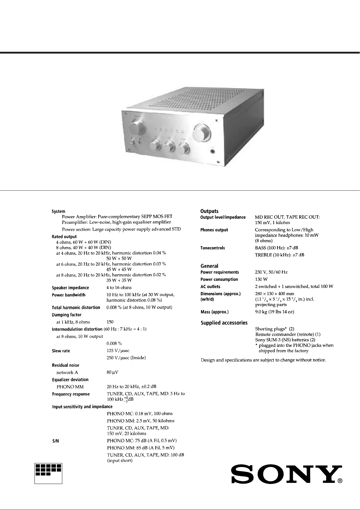
Photo: TA-F3000
SPECIFICATIONS
AEP Model
UK Model
TA-F3000ES
E Model
Chinese Model
TA-F3000
MICROFILM
INTEGRATED STEREO AMPLIFIER
— 1 —

TABLE OF CONTENTS
1. GENERAL
.......................................................................... 3
2. ELECTRICAL ADJUSTMENTS .................................. 4
3. DIAGRAMS
3-1. Circuit Boards Location........................................................4
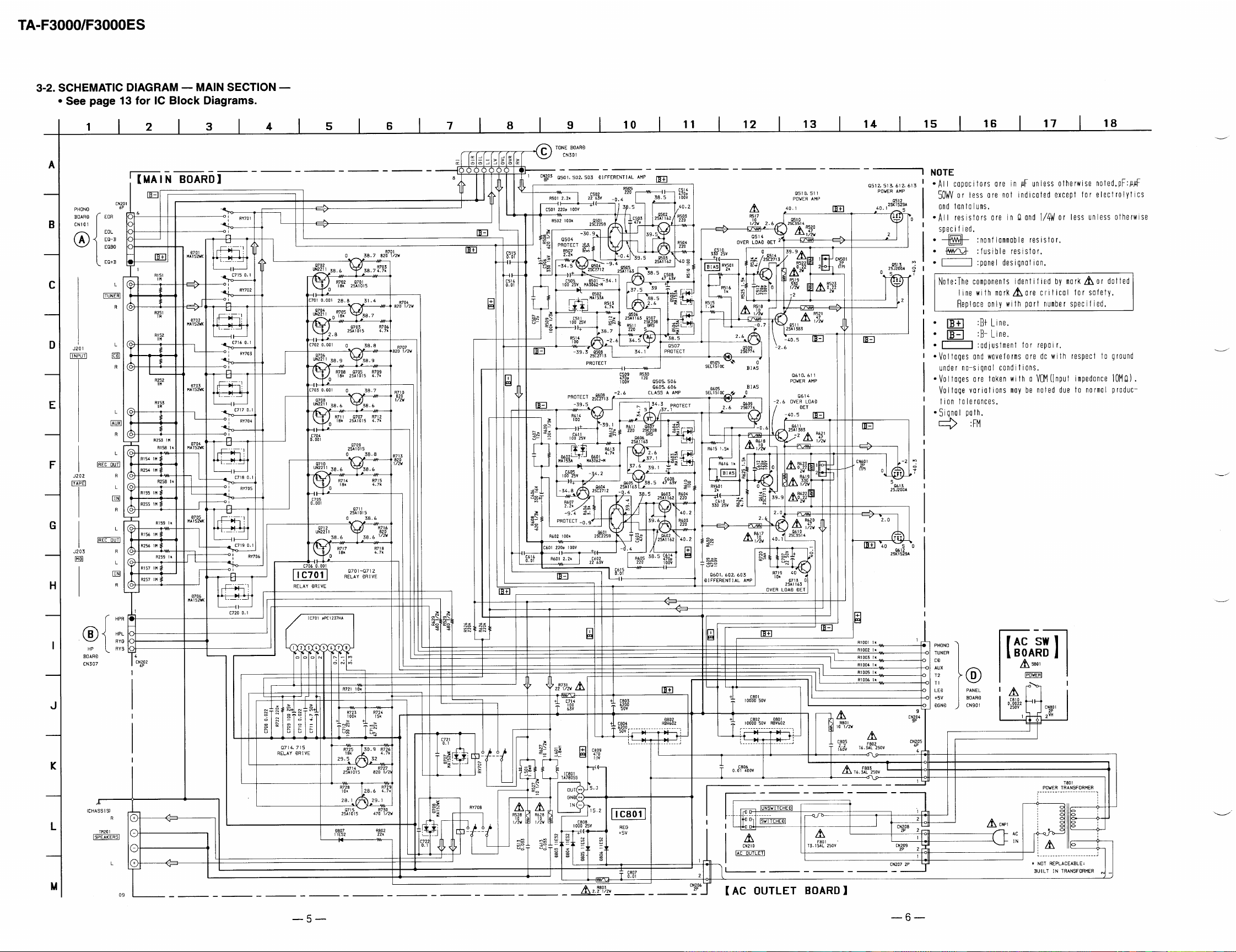
3-2. Schematic Diagram — Main Section — ..............................5
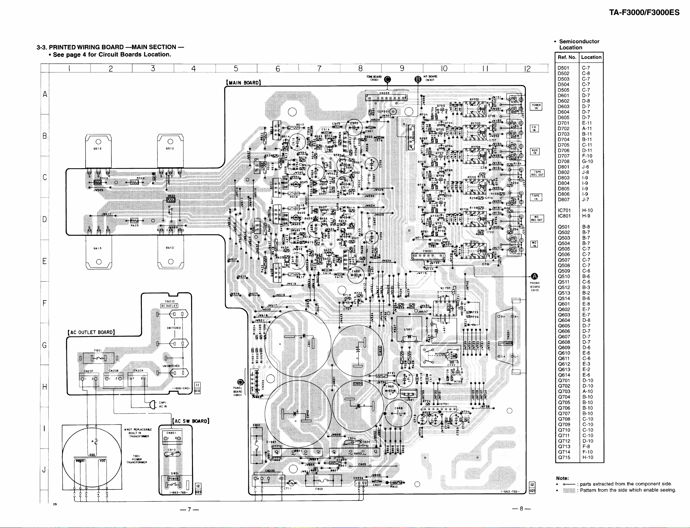
3-3. Printed Wiring Board — Main Section —............................7
3-4. Schematic Diagram — Panel Section — .............................. 9
3-5. Printed Wiring Board — Panel Section — ......................... 11
3-6. IC Block Diagrams .............................................................13
3-7. IC Pin Function ...................................................................14
4. EXPLODED VIEWS
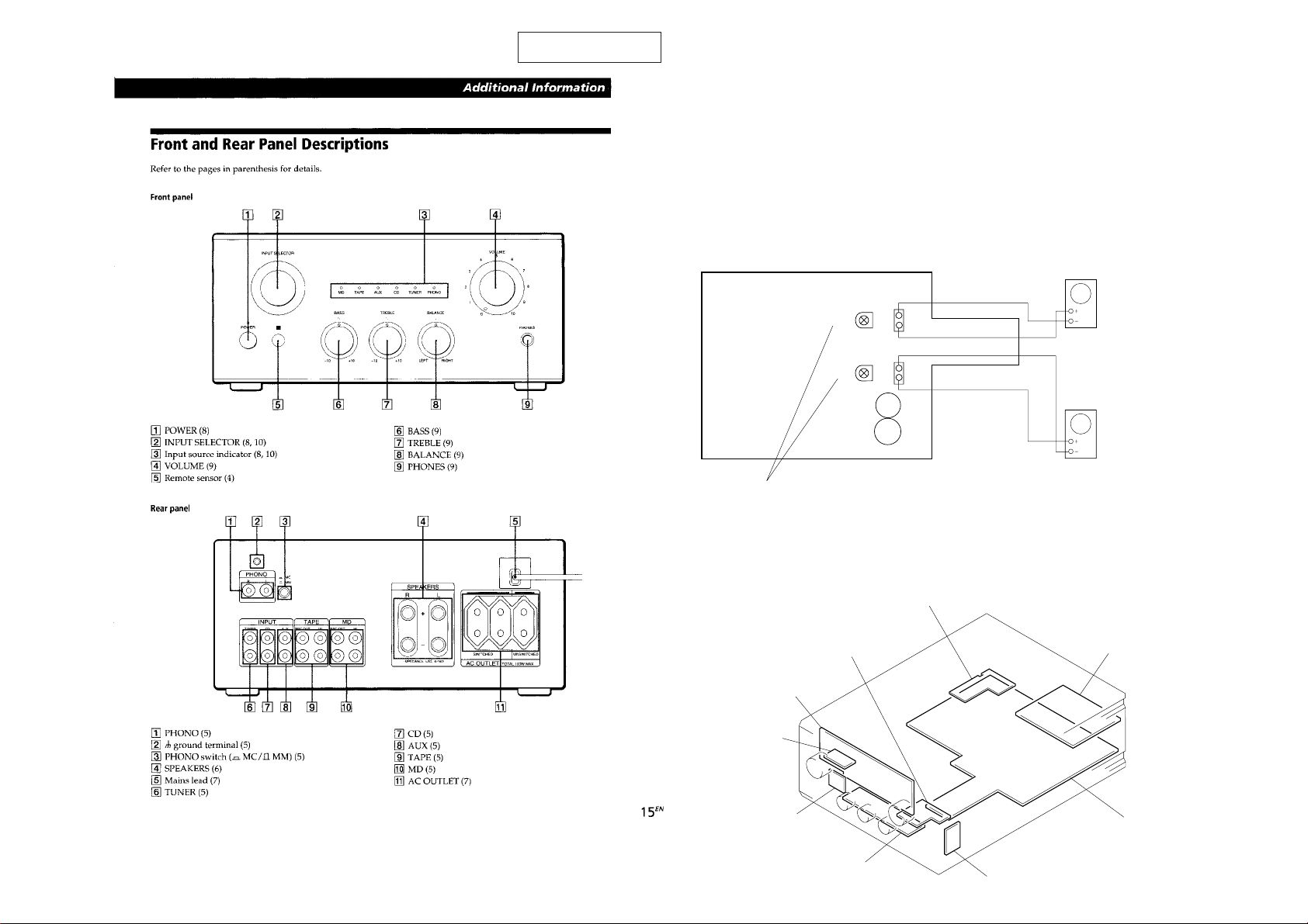
4-1. Front Panel Section.............................................................15
4-2. Chassis Section ................................................................... 16
5. ELECTRICAL PARTS LIST ........................................ 17
Notes on chip component replacement
• Never reuse a disconnected chip component.
• Notice that the minus side of a tantalum capacitor may be
damaged by heat.
Flexible Circuit Board Repairing
• Keep the temperature of soldering iron around 270˚C
during repairing.
• Do not touch the soldering iron on the same conductor of the
circuit board (within 3 times).
• Be careful not to apply force on the conductor when soldering
or unsoldering.
SAFETY-RELATED COMPONENT WARNING !!
COMPONENTS IDENTIFIED BY MARK ! OR DO TTED LINE
WITH MARK ! ON THE SCHEMATIC DIAGRAMS AND IN
THE PARTS LIST ARE CRITICAL TO SAFE OPERATION.
REPLACE THESE COMPONENTS WITH SONY PARTS
WHOSE PART NUMBERS APPEAR AS SHOWN IN THIS
MANUAL OR IN SUPPLEMENTS PUBLISHED BY SONY.
— 2 —
SECTION 1
GENERAL
This section is extracted from
instruction manual.
ELECTRICAL ADJUSTMENTS
Bias Adjustment
1. Rotate the semi-fixed resistors (RV501, RV601) for bias
adjustment to the MIN side fully (counterclockwise direction).
2. Connect a digital voltmeter to CN501 (TP) and CN601
(TP).
1P : ’ side, 2P : ‘ side
3. Turn ON the power button, and adjust RV501 and RV601
so that the digital voltmeter display becomes 22 mV ± 2mV
within 5 seconds.
4. After the adjustment, turn OFF the power button.
Adjustment Location
[MAIN BOARD] (Component side)
CN501 (TP)
RV501
RV601
C801
C802
Bias Adjustment
1
2
CN601 (TP)
1
2
SECTION 2
Digital volt meter
Digital volt meter
— 3 —
3-1. CIRCUIT BOARDS LOCATION
VOL board
PANEL board
RM board
AC SW board
TONE board
SECTION 3
DIAGRAMS
AC OUTLET board
PHONO board
MAIN board
HP board
— 4 —
 Loading...