


3-861-065-11(1)
Integrated AV
Amplifier
Operating Instructions |
|
|
GB |
|||
|
|
|
||||
|
|
|
|
|
|
|
Mode d’emploi |
|
|
|
|
F |
|
|
|
|
|
|||
|
|
|
|
|
|
|
Gebruiksaanwijzing |
|
|
|
NL |
||
|
|
|
||||
|
|
|
|
|
|
|
Bruksanvisning |
|
|
|
|
|
S |
|
|
|
||||
TA-VE810G
© 1997 by Sony Corporation

WARNING
To prevent fire or shock hazard, do not expose the unit to rain or moisture.
To avoid electrical shock, do not open the cabinet. Refer servicing to qualified personnel only.
This amplifier incorporates the Dolby* Pro Logic Surround system.
*Manufactured under license from Dolby Laboratories Licensing Corporation. DOLBY, the double-D symbol a, “AC-3” and
“PRO LOGIC” are trademarks of Dolby Laboratories Licensing Corporation.
Precautions |
About This Manual |
On safety
•Should any solid object or liquid fall into the cabinet, unplug the amplifier and have it checked by qualified personnel before operating it any further.
On power sources
•Before operating the amplifier, check that the operating voltage is identical with your local power supply. The operating voltage is indicated on the nameplate at the rear of the amplifier.
•This unit is not disconnected from the AC power source (mains) as long as it is connected to the wall outlet, even if the unit itself has been turned off.
•If you are not going to use the amplifier for a long time, be sure to disconnect the amplifier from the wall outlet. To disconnect the mains lead, grasp the plug itself; never pull the cord.
•AC power cord must be changed only at the qualified service shop.
On placement
•Do not install the appliance in a confined space, such as a bookcase or built-in cabinet.
•Place the amplifier in a location with adequate ventilation to prevent heat buildup and prolong the life of the amplifier.
•Do not place the amplifier near heat sources, or in a place subject to direct sunlight, excessive dust or mechanical shock.
•Do not place anything on top of the cabinet that might block the ventilation holes and cause malfunctions.
On operation
•Before connecting other components, be sure to turn off and unplug the amplifier.
On cleaning
•Clean the cabinet, panel and controls with a soft cloth slightly moistened with a mild detergent solution. Do not use any type of abrasive pad, scouring powder or solvent such as alcohol or benzine.
If you have any question or problem concerning your amplifier, please consult your nearest Sony dealer.
This manual is divided into three sections; Getting Started, On-screen Operations and Front Panel Operations.
The “Getting Started” section describes connections, how to set up the remote for on-screen control, and Dolby Pro Logic Surround.
The “On-Screen Operations” section describes how to operate the amplifier using the remote to manipulate the on-screen display on your TV screen. The remote lets you perform almost all of the amplifier operations.
You can also control the amplifier without the remote. The “Front Panel Operations” section describes how to operate the amplifier using the front panel controls and remote short-cut buttons.
The following icon is used in this manual:
Indicates hints and tips for z making the task easier.
2GB

Table of contents
Welcome! 4
Hooking Up the System
Hookup Overview 5
Infrared (IR) Repeater Hookups 6
Audio Component Hookups 6
Speaker System Hookups 7
TV/VCR Hookups 8
AC Hookups 10
Setting Up the Remote for On-Screen Control
Using the Remote 11
Registering a TV (or Monitor) 13
Registering Audio and Video Components 15
Dolby Pro Logic Surround Setup
What is Dolby Pro Logic Surround? 18
Adjusting the Speaker Volume 19
Playback/Recording
Selecting a Component 20
Watching TV or Video Programmes 21
Recording 22
Sound Adjustment
Using the Pre-programmed Sound Field 24
Customizing the Sound Fields 25
Additional Operations and Settings
Registering Desired Component (User IR setting) 28 Indexing 29
Playing Sources Automatically (Auto Play) 30
Starting a Source Automatically at Power On (Auto Start) 30 Starting Several Components in Sequence Automatically
(Macro Play) 31
Adjusting the Sensitivity of the Remote 32 Changing the Display Settings 32
Using the Sleep Timer 34 Operating a CD Changer 34
Front Panel Operations
Front Panel Descriptions 37
Remote Descriptions 38
Selecting a Component 38
Recording 39
Adjusting the Sound 40
Customizing the Amplifier Operations 41
Indexing 42
Playing Components Without the TV (Flasher) 42
Additional Information
Troubleshooting 44
Specifications 46
Glossary 47
Index 48
Started Getting
Operations Screen-On
Panel Front
Operations
GB
3GB
Welcome!
Thank you for purchasing the TA-VE810G Sony Integrated AV Amplifier.
Your new amplifier is an audio/video control centre with a unique interface. When you connect the amplifier to your TV, an on-screen display (shown below) appears and lets you operate the various connected audio/video components with this amplifier’s remote.
Also, the on-screen display lets you control any other device that can be controlled by an infrared remote control, such as air conditioners.
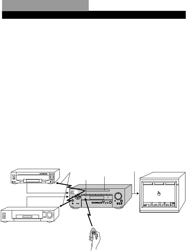
Understanding How the Amplifier Works
1The remote emits an infrared (IR) signal when you press direction control button (see 1 below).
2This controls the movement of the pointer (handshaped icon) in the on-screen display (see 2 below).
3When you move the pointer to an on-screen icon, and press the centre of the direction control button on the remote, the infrared (IR) emitter on the front panel transmits the corresponding IR control code to the respective component (see 3 below).
LD player, etc.
Video signal
Video signal
|
Video signal (Input from source |
|
components combined with on-screen |
IR control codes |
display) |
|
IR emitter
IR receptor
TA-VE810G |
|
SOUND |
|
SETUP |
||
FUNCTION |
|
|
||||
3 |
|
 |
2 |
|
|
|
|
M |
m |
|
|
|
|
|
|
|
|
|
||
|
|
µ |
|
|
|
|
|
INPUT |
SUB |
USER |
|
||
0 |
( |
) |
p |
P |
= |
+ |
TV (monitor)
VCR, etc. |
1 |
4GB
Hooking Up the System
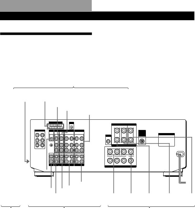
Hookup Overview
The amplifier allows you to connect and control the following audio/video components. For details on connection of each component, see the pages in parentheses.
TV/VCR Hookups (8)
Video camera/ |
|
TV/MONITOR |
|
|
|
Satellite decoder |
|
LD/DVD |
|
VCR |
||||
video game |
|
|
|
|
|
player |
|
|||||||
|
|
|
|
|
|
|
|
|
|
|
|
|||
|
|
|
|
|
|
|
|
|
|
|
|
|
|
|
|
|
|
|
|
|
|
|
|
|
|
|
|
|
|
|
|
|
|
|
|
|
|
|
|
|
|
|
|
|
|
|
|
|
|
|
|
|
|
|
|
|
|
|
|
|
MONITOR |
S-LINK |
|
|
SURROUND SPEAKERS |
|
|
|
|
|
|
|
|
5-1 INPUT |
IR OUT SATL LD/DVD |
VIDEO 2 |
VIDEO 1 |
|
WIRELESS |
|
|
|
|
|
|
|
|
|
|
|
|
|
REAR |
AC OUTLET |
|
|
|
|
WOOFER |
SPEAKER |
|
|
|
|
|
|
||
|
|
|
|
|
|
|
|
|
|
|
|
IMPEDANCE USE 8-16Ω |
|
To the front panel
PHONO TUNER CD DAT / MD |
TAPE |
FRONT SPEAKERS
|
|
|
|
|
|
|
|
|
|
|
|
|
|
|
|
|
|
|
|
|
|
|
|
|
|
|
|
|
|
|
|
|
|
|
|
|
|
|
|
|
|
|
|
|
|
|
|
|
|
|
|
|
|
|
|
|
|
|
|
|
|
|
|
|
|
|
|
|
|
|
|
|
|
|
|
|
|
|
|
|
|
|
|
|
|
|
|
|
|
|
|
|
|
|
|
|
|
|
|
|
|
|
|
|
|
|
|
|
|
|
|
|
|
|
|
|
|
|
|
|
|
|
|
|
|
|
|
|
|
|
|
|
|
|
|
|
|
|
|
|
|
|
|
|
|
|
|
|
|
|
|
|
|
|
|
|
|
|
|
|
|
|
|
|
|
|
|
|
|
|
|
|
|
|
|
|
|
|
|
|
|
|
|
|
|
|
|
|
|
|
|
|
|
|
|
|
|
|
|
|
|
|
|
|
|
|
|
|
|
|
|
|
|
|
|
|
|
|
|
|
|
|
|
|
|
|
|
|
|
|
IR Repeater |
|
Turntable |
|
|
Tuner |
|
CD |
|
DAT/MD |
|
Tape |
|
Front |
|
Front |
|
Rear |
|
|
Rear |
|
Centre |
||||||||||
|
|
|
|
player |
|
deck |
|
deck |
|
speaker (R) |
|
speaker (L) |
|
speaker (R) |
|
speaker (L) |
|
speaker |
||||||||||||||
|
|
|
|
|
|
|
|
|
|
|
|
|
|
|
|
|
|
|
|
|||||||||||||
|
|
|
|
|
|
|
|
|
|
|
|
|
|
|
|
|
|
|
|
|
|
|
|
|
||||||||
Infrared (IR) |
|
|
|
|
Audio Component Hookups (6) |
|
|
|
|
|
Speaker System Hookups (7) |
|
||||||||||||||||||||
Repeater |
|
|
|
|
|
|
|
|
|
|
|
|
|
|
|
|
|
|
|
|
|
|
|
|
|
|
|
|
|
|
|
|
Hookups (6) |
|
|
|
|
|
|
|
|
|
|
|
|
|
|
|
|
|
|
|
|
|
|
|
|
|
|
|
|
|
|
|
|
Before you get started
•Check that you received the following items with the amplifier:
-Remote commander RM-VR101 (remote) (1)
-Size AA (R6) batteries (2)
-IR repeater (1)
•Turn off the power to all components before making any connections.
•Do not connect the mains leads until all of the connections are completed.
•Be sure to make connections firmly to avoid hum and noise.
5GB
Hooking Up the System
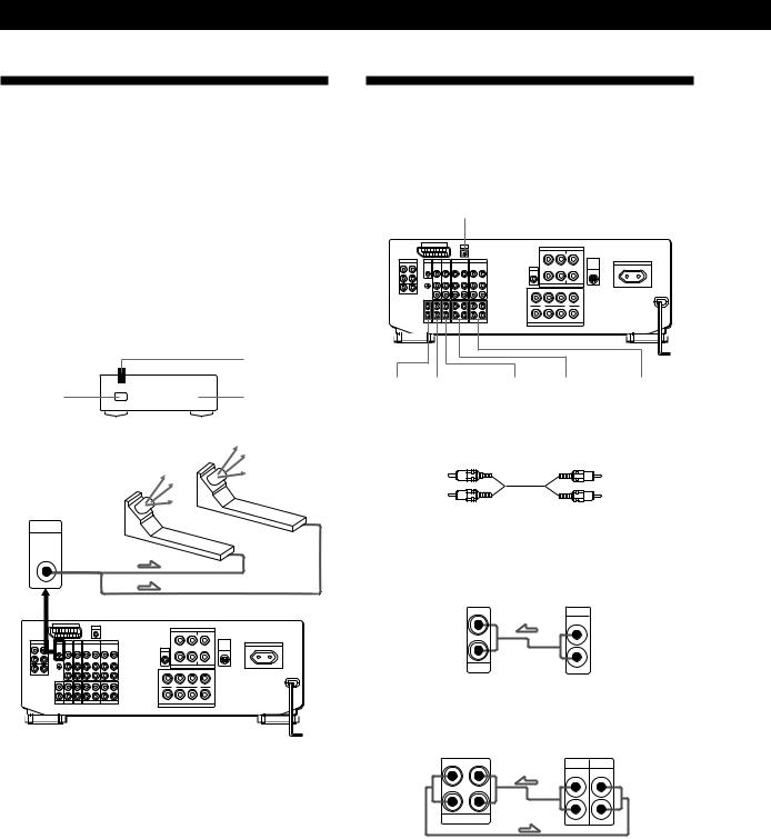
Infrared (IR) Repeater Hookups
The IR repeater emits infrared signals corresponding to those emitted by the remote controls supplied with the components. Connect the IR repeater if:
•You experience difficulty controlling a certain component using the on-screen display control.
•Your installation configuration prevents the IR repeater on the amplifier’s front panel from reaching all of the components you need to control.
After connecting the IR repeater, set it above or below the IR sensor on the component(s) to be controlled. Each IR repeater can send infrared signals to one component.
|
IR repeater |
IR sensor |
µ |
Component |
|
|
infrared |
|
signals |
IR OUT
IR repeater(s)
Note
Use the supplied adhesive tape to secure the IR repeater so that its front faces the component to be controlled.
Audio Component Hookups
If your components are Sony products, connect them to the jacks as shown in the table on page 15 so that the IR registration is unnecessary.
S-LINK/CTRL A1
e PHONO d TUNER a CD c DAT/MD b TAPE
What cords will I need?
Audio cord (not supplied)
White (L) |
White (L) |
Red (R) |
Red (R) |
Ç: signal flow a CD (to CD player)
Amplifier |
CD player |
IN |
OUTPUT |
L |
LINE |
|
|
R |
|
CD |
|
b TAPE (to a tape deck)
Amplifier
RECOUT IN
L
R
TAPE
Tape deck
OUTPUT INPUT
LINE LINE
L
R
6GB
c DAT/MD (to DAT/MD deck)
Amplifier DAT/MD
RECOUT |
IN |
OUTPUT |
INPUT |
L |
|
LINE |
LINE |
L
R
R
DAT / MD
d TUNER (to a tuner)
Amplifier Tuner
IN |
OUTPUT |
LINE
L
R
TUNER
e PHONO (to a turntable)*
Amplifier
Turntable
L
OUTPUT
R
PHONO
*If your turntable has an earth lead, connect it to y SIGNAL GND on the unit to prevent hum.
zTo use Sony components with a CONTROL A1 terminal
You can connect a CONTROL A1 compatible Sony CD player, tape deck or MD deck to the amplifier. Use a CONTROL A1 cord (not supplied) to connect the CTRL A1 jack on each component to the S-LINK CTRL A1 jack on the amplifier. See the instructions for each component.
zYou can display the operating status of the component connected to the CTRL A1 jack
See page 41.
zTo use a Sony CD changer with a COMMAND MODE selector
•If the changer does not have a VIDEO OUT jack, set the command mode to “CD 1” and connect the changer to the CD jack on the amplifier.
•If the changer has a VIDEO OUT jack, set the command mode to “CD 2” and connect the changer to the VIDEO 1, VIDEO 2, or LD jack on the amplifier.
Hooking Up the System
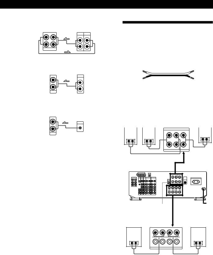
Speaker System Hookups
Although front (left and right) speakers are required, centre and rear speakers are required only for enjoying surround sound.
What cords will I need?
Speaker cord (not supplied)
(+) |
(+) |
(–) |
(–) |
Twist the stripped ends of the cord about 2/3 inch (15 mm). Be sure to match the speaker cord to the appropriate terminal on the components: + to + and – to –. If the cords are reversed, the sound will be distorted and will lack bass.
Rear |
Rear |
|
|
Centre |
||||
speaker (L) |
speaker (R) |
Amplifier |
speaker |
|||||
|
|
|
|
|
SURROUND SPEAKERS |
|
|
|
|
|
|
|
|
|
|
||
|
|
|
|
|
R REAR L |
CENTER |
|
|
++
--
R L
IMPEDAMCE USE 4-16Ω
|
WOOFER |
|
|
|
AUDIO |
|
|
|
OUT |
|
|
Front speaker (R) |
|
|
Front speaker (L) |
+ |
- |
- |
+ |
A |
|
|
A |
R |
- |
- |
L |
+ |
+ |
||
B |
|
|
B |
|
IMPEDANCE USE 4-16Ω |
|
|
|
FRONT |
SPEAKERS |
|
(continued)
7GB
Hooking Up the System
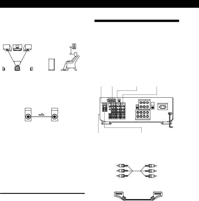
Speaker placement
For optimum surround sound effect, place your speakers as shown below.
Rear speaker
60 - 90 cm (2 - 3 feet)
Front speaker
zYou can connect an active woofer
You can reinforce the bass sound by connecting an optional active woofer to the WOOFER AUDIO OUT terminal.
Amplifier |
Active woofer |
WDOFER |
INPUT |
AUDIO |
|
OUT |
|
zYou can connect wireless rear speakers
When using an optional Sony wireless rear speaker system, connect the transmitter to the WIRELESS REAR SPEAKER connector.
Note
Do not connect any other components to the WIRELESS REAR SPEAKER connector.
Selecting the speaker system
You can connect one set or two sets of speakers. Set the SPEAKERS selector on the front panel according to your speaker system.
To drive |
Set SPEAKERS selector to |
|
|
Speaker system A |
A |
(connected to the FRONT |
|
SPEAKERS A terminals) |
|
|
|
Speaker system B |
B |
(connected to the FRONT |
|
SPEAKERS B terminals) |
|
|
|
Both speaker systems A and B |
A+B* |
(parallel connection) |
|
|
|
*Connect speakers with nominal impedance of 8 ohms, or higher, to the A and B terminals.
TV-VCR Hookups
You must connect a TV to control the amplifier using the on-screen display. Also, to enjoy the Dolby Pro Logic Surround encoded videos and TV programmes, you need to connect TV and VCRs together with the centre and rear speakers.
If your components are Sony products, connect them to the jacks as shown in the table on page 15, this makes IR registration is unnecessary.
d SATL a MONITOR c LD/DVD b VIDEO 1, 2
e VIDEO 3 INPUT |
5.1 INPUT |
(on the front panel) |
|
What cables will I need?
• Audio/video cable (not supplied)
Yellow |
Yellow |
White (L) |
White (L) |
Red (R) |
Red (R) |
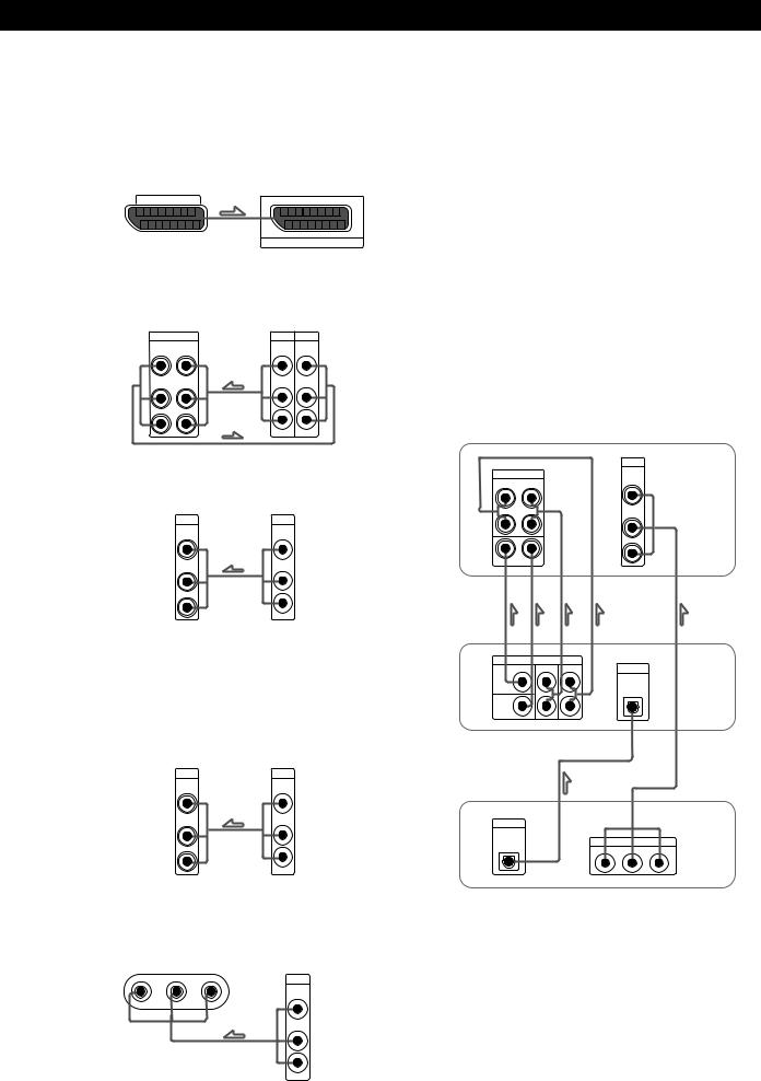
• SCART cable (not supplied)
Make sure to match the colour of the plugs and the jacks: Yellow (video) to Yellow; White (left, audio) to White; and Red (right, audio) to Red.
Ç: signal flow
8GB
Hooking Up the System
a MONITOR (to TV or monitor)
Be sure to use your TV as a monitor, and use the TV tuner built-in to the VCR to watch TV programmes. If you use your TV’s tuner, the on-screen display will change to a TV programme when you switch channels.
Amplifier Monitor
MONITOR
AV 1
b VIDEO 1, 2 (to VCR)
Connect VCRs to the VIDEO 1 or/and VIDEO 2 jacks.
Amplifier |
VCR |
||
VIDEO 1 |
OUTPUT |
INPUT |
|
VIDEO |
VIDEO |
VIDEO |
VIDEO |
OUT |
IN |
||
AUDIO |
AUDIO |
AUDIO |
AUDIO |
OUT |
IN |
|
|
|
|
|
L |
|
|
L |
|
|
|
R |
R |
|
|
|
|
c LD/DVD (to LD or DVD player)
Amplifier |
LD/DVD |
LD/DVD |
OUTPUT |
VIDEO |
VIDEO |
IN |
|
AUDIO |
AUDIO |
IN |
|
|
L |
L |
|
R |
R |
|
Note
To input decoded Dolby Digital (AC-3) soundtracks, make connections as shown below in “Playing decoded Dolby Digital (AC-3) soundtracks”.
d SATL (to a satellite decoder)
Amplifier |
Satellite decoder |
SATL |
OUTPUT |
VIDEO |
VIDEO |
IN |
|
AUDIO |
AUDIO |
IN |
|
|
L |
L |
|
R |
R |
|
e VIDEO 3 INPUT (to a video camera or a video game)
|
Amplifier |
Video camera/ |
(front panel) |
video game |
|
VIDEO 3 INPUT |
|
OUTPUT |
|
|
VIDEO |
VIDEO |
L AUDIO R |
|
AUDIO
L
R
zIf you have a CANAL+ tuner
Connect it to the VTR connected to the amplifier’s VIDEO 1 jacks.
Note
Set the TV tuner to skip channels where there is no broadcast so that an image is always displayed on the TV screen; otherwise, the on-screen display is distorted.
Playing decoded Dolby Digital (AC-3) soundtracks
If you have a Dolby Digital (AC-3) decoder, you can use the amplifier to amplify decoded Dolby Digital (AC-3) soundtracks with the following connections.
These audio signals are paired with the video signals input to the LD/DVD VIDEO IN jack (see page 21 for details regarding operation).
|
|
Amplifier |
|
|
LD/DVD |
5-1 |
INPUT |
VIDEO |
FRONT |
REAR |
IN |
|
||
L |
|
|
|
|
AUDIO |
|
|
IN |
R |
|
|
|
|
L |
CENTER |
WOOFER |
R |
|
PRE OUT
REAR FRONT |
DIGITAL |
CENTER
IN
WOOFER
Dolby Digital (AC-3) decoder (etc.)
DIGITAL
LINE OUT
OUT |
R - AUDIO - L |
VIDEO |
DVD player
9GB
Hooking Up the System
AC Hookups
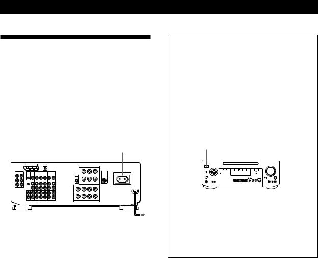
Connecting the mains lead
Connect the mains lead from this amplifier and from your audio/video components to a wall outlet.
If you connect another audio component to the SWITCHED AC OUTLET on the amplifier, the amplifier can supply power to the connected component so you can turn it on/off when you turn on/off the amplifier.
SWITCHED AC OUTLET
to a wall outlet
Caution
Make sure that the power consumption of the component connected to the amplifier’s AC outlet does not exceed the wattage indicated on the rear panel. Do not connect highwattage electrical home appliances such as electric irons, fans, or TVs to this outlet.
Before using for the first time
Be sure to clear the amplifier’s memory before using for the first time.
1Make sure the POWER is set to off.
2While holding down the VIDEO FUNCTION >, AUDIO FUNCTION > and SOUND FIELD MODE buttons, press POWER to turn on the amplifier.
“ALL CLEAR!” appears in the display.
POWER
|
|
|
|
|
|
|
|
|
|
|
|
|
|
|
|
|
|
|
|
|
|
|
|
|
|
|
|
|
|
|
|
|
|
|
|
|
|
|
|
|
|
|
AUDIO |
|
|
||||
VIDEO |
SOUND FIELD |
||||||||
FUNCTION |
|||||||||
FUNCTION |
> |
|
|
MODE |
|||||
> |
|
|
|
|
|||||
|
|
|
|
|
|
|
|||
Note
Clearing the amplifier’s memory erases all IR code settings etc.
10GB
Setting Up the Remote for On-Screen Control
Using the Remote
Inserting batteries into the remote
1 Open the cover on the bottom of the remote.
2Insert two size AA (R6) batteries with correct polarity (+/–), then close the cover.
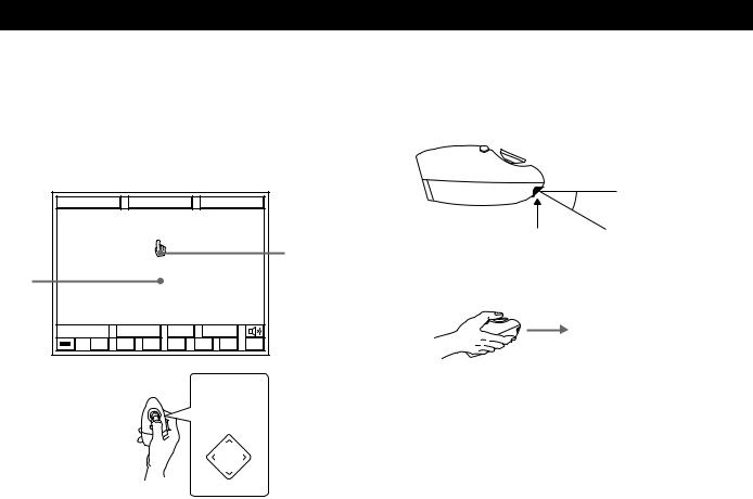
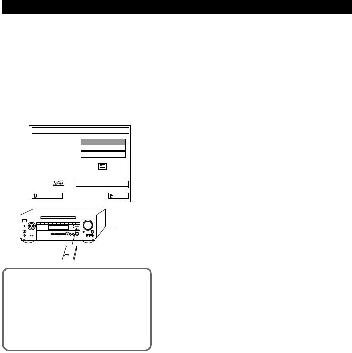
Turning on the amplifier and bringing up the on-screen display on your TV (or monitor)
To turn on the amplifier, point the remote at the IR receptor, and then press the direction control button on the remote once or twice. To bring up the on-screen display, turn on your TV and set it to the appropriate video input. If you register the IR code of your TV (see “Registering a TV (or Monitor)” on page 13), you can turn on your TV automatically whenever you turn on the amplifier.
b |
IR receptor |
|
Notes on the remote
Battery life
Under normal use, the batteries should last for about 6 months. When the remote no longer operates the amplifier, replace both batteries with new ones.
Notes
•Do not leave the remote in an extremely hot or humid place.
•Do not use a new battery with an old one.
•Do not expose the remote sensor to direct sunlight or lighting apparatuses. Doing so may cause a malfunction.
•If you don’t use the remote for an extended period of time, remove the batteries to avoid possible damage from battery leakage and corrosion.
Direction control button
PUSH
ENTER
(continued)
11GB
Setting Up the Remote for On-Screen Control
How to use the remote
The supplied remote lets you perform almost all of the amplifier operations.
This section describes how to use the direction control button. For other remote operations, see page 38.
FUNCTION |
|
SOUND |
|
SETUP |
||
Blank |
|
|
|
|
|
Pointer |
|
|
|
|
|
|
|
area |
|
|
|
|
|
|
|
INPUT |
SUB |
USER |
|
||
0 |
( |
) |
p |
P |
= |
+ |
Direction control
button
Â
M |
PUSH |
m |
ENTER |
µ
1Press the direction control button on the remote once to recall the on-screen display.
2Press repeatedly (or hold down) the corner of the direction control button (M, m, Â, µ) in the direction you want to move the pointer (handshaped icon) on the on-screen display.
3To “click” on an item, position the pointer so that it is on one of the on-screen items, then press and quickly release the centre of the direction control button (indicated by “PUSH ENTER”).
To make the on-screen display disappear
Position the pointer in the blank area, and press the centre of the direction control button.
Notes on handling the remote
•Do not cover the IR emitter on the remote when operating the remote.
30°
IR emitter
•Hold the remote with its direction control button facing up, as shown below.
12GB
Setting Up the Remote for On-Screen Control |
|||
4 |
• Sony TV |
|
|
Registering a TV (or Monitor) |
1 Click Sony TV. |
|
|
|
The IR codes are automatically registered |
||
You must register the IR code of your TV (or monitor) |
and registration is complete. |
|
|
in order to turn on your TV automatically whenever |
|
|
|
you turn on the amplifier. |
|
TV MONITOR SET |
|
IR code registration is unnecessary in the |
TV IR SET |
Sony |
TV |
|
OTHER TV |
||
following case |
|
|
|
If your TV is a Sony product that can be controlled by |
|
|
|
an infrared remote, and it is connected to the amplifier |
|
|
|
by its VIDEO 1 video input jack, you do not need to |
|
|
|
register its IR code. |
RETURN |
|
EXIT |
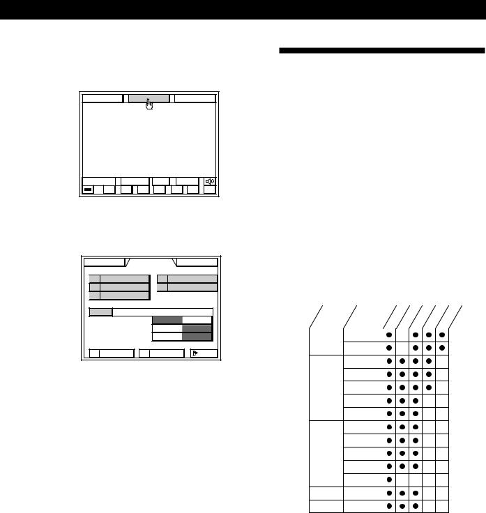
Registering IR codes
1Turn on the amplifier and the TV.
Make sure the input selector on the TV is set to the video input.
2Click SETUP in the main menu.
FUNCTION |
|
SOUND |
|
SETUP |
||
|
INPUT |
SUB |
USER |
|
||
0 |
( |
) |
p |
P |
= |
+ |
3 Click TV SET.
FUNCTION |
SOUND |
SETUP |
|
TV |
SET |
FUNC |
INDEX |
IR |
SET |
CD |
INDEX |
USER IR |
TUNER |
INDEX |
|
AUTO START |
SLEEP TIMER |
||
MACRO PLAY |
OSD SETUP |
||
|
|
|
EXIT |
• Non-Sony TV
1Click OTHER TV.
2Go to step 5.
|
TV MONITOR SET |
|
TV IR SET |
Sony |
TV |
|
OTHER TV |
|
RETURN |
|
EXIT |
5Cover the IR sensor on the TV to prevent accidental operation. Otherwise, the on-screen display may be turned off during the registration procedure.
6Click START.
|
TV MONITOR SET |
|
TV IR SET |
Sony |
TV |
|
OTHER TV |
|
|
START |
|
RETURN |
|
EXIT |
(continued)
13GB
Setting Up the Remote for On-Screen Control
7When “PUSH YOUR REMOTE” appears in the on-screen display, press the button on the TV's remote that corresponds to the highlighted control button (e.g., POWER OFF).
•TV/VIDEO : Use to program the cyclic input selector button on your TV’s remote. This allows you to switch the TV’s input selector using this unit’s remote. Do not program an independant input selector button at this setting.
•WIDE TV DISPLAY MODE: Use to program the wide TV mode button on your TV’s remote.
|
TV IR SET |
TV IR SET |
CHANNEL 0 |
|
POWER OFF |
|
TV / VIDEO |
WIDE TV DISPLAY MODE |
|
PUSH |
YOUR REMOTE |
|
CODE CLEAR |
RETURN |
EXIT |
IR sensor
TV's remote
When registering the IR code, be sure to do the following; otherwise, the IR code may not be registered correctly.
•Point the remote at the IR sensor on the
amplifier from a distance of less than 1 inch (3 cm).
•Hold down the button on the remote for about 2 or 3 seconds until the “RECEIVING” display switches to “RELEASE YOUR REMOTE”.
•Keep the remote pointed horizontally at the IR sensor until the code is registered.
8Repeat step 7 for the remaining buttons that appear in the on-screen display.
If “NG” is displayed, an IR code was not registered correctly. In this case, repeat step 7 again.
To return to the main menu
Click EXIT.
To return to a previous menu
Click RETURN.
Note
Some IR codes may not have been successfully registered, even if “RELEASE YOUR REMOTE” appears on the TV screen. In this case, try registering the IR code again. If the IR code still cannot be registered, follow the procedure described in “Registering Desired Components (User IR setting)” on page 28.
Erasing TV IR codes
Click CODE CLEAR in the TV IR SET menu that appears when you click START.
•To erase a specific IR code
1Click SINGLE IR CODE CLEAR. “SELECT CLEAR CODE KEY” appears.
2Click the button you want to clear. “Are you sure?” appears.
3Click YES to erase the code. To cancel erasing, click NO.
To erase another code repeat steps 2 and 3.
•To erase all the TV IR codes
1Click TV IR CODE CLEAR. “Are you sure?” appears.
2Click YES to erase the codes.
“CODE CLEAR!” appears in the display. To cancel erasing, click NO.
14GB
Setting Up the Remote for On-Screen Control
Registering Audio and Video
Components
You must register the IR code of your audio/video component to control your component using the onscreen display.
IR code registration is unnecessary in the following case
If your audio/video component is a Sony product that can be controlled by an infrared remote, and it is connected to the jacks shown in the following table, you do not need to register the IR code.
Amplifier jacks |
Component to be connected |
|
|
|
|
VIDEO 1 |
Sony VTR 3 |
(VHS) |
|
|
|
VIDEO 2 |
Sony VTR 1 |
(BETA) |
|
|
|
VIDEO 3 |
Sony VTR 2 |
(8 mm) |
|
|
|
LD/DVD |
Sony LD player |
|
|
|
|
SATL |
Sony Satellite receiver |
|
|
|
|
TUNER |
Sony Tuner |
|
|
|
|
DAT/MD |
Sony DAT deck |
|
|
|
|
CD |
Sony CD player (CD 1) |
|
|
|
|
TAPE |
Sony Tape deck |
|
|
|
|
MONITOR |
Sony TV (via its VIDEO 1 jack) |
|
|
|
|
The following cases require registration of Sony products
•When connecting a Sony MD deck to the DAT/MD jacks.
•When connecting a Sony audio product with CONTROL-A1 compatibility.
•When connecting a Sony product to jacks other than those specified in the previous table (e.g., when connecting a Sony LD player to the VIDEO 3 jacks).
•When exchanging a non-Sony audio or video component with a Sony product.
Notes
•If your VCR has a COMMAND CODE selector switch (for VTR1, VTR2, or VTR3), set the switch to the applicable setting. If your VCR has a built-in StarSight tuner, you must set the COMMAND CODE selector switch to VTR 3.
•If your CD changer has a COMMAND MODE selector switch (for CD 1, CD 2, or CD 3), normally it should be set to “CD 1.” However, if your CD changer has VIDEO OUT terminals, set the command mode to “CD 2” or “CD 3” (“CD 3” should be used only when making CONTROL-A1 connections).
Registering IR codes
1 Click SETUP in the main menu.
|
FUNCTION |
SOUND |
SETUP |
|
2 |
Click IR SET. |
|
|
|
|
FUNCTION |
SOUND |
SETUP |
|
|
TV |
SET |
FUNC |
INDEX |
|
IR |
SET |
CD |
INDEX |
|
USER IR |
TUNER |
INDEX |
|
|
AUTO START |
SLEEP TIMER |
||
|
MACRO PLAY |
OSD SETUP |
||
|
|
|
|
EXIT |
3 Click the name of the amplifier's jack you want.
IR CODE SETTING |
|||
VIDEO |
1 |
Sony |
VTR3 |
VIDEO |
2 |
Sony |
VTR1 |
VIDEO |
3 |
Sony |
VTR2 |
LD/DVD |
|
Sony |
LD |
SATL |
|
Sony |
SATL |
TAPE |
|
Sony |
TAPE |
DAT/MD |
|
Sony |
DAT |
CD |
|
Sony |
CD1 |
TUNER |
|
Sony |
TUNER |
RETURN |
|
|
EXIT |
Amplifier's jacks Connected component
4• Sony product Click Sony.
The IR codes are automatically registered and registration is complete.
IR CODE SETTING |
|
|
MAKER |
Sony |
OTHER |
OUTPUT |
IR |
|
To take advantage of CONTROL-A1 compatible audio components, such as multi-disc CD players, click CONTROL-A1 to select CONTROL-A1.
• non-Sony product Click OTHER.
IR CODE SETTING |
|
|
MAKER |
Sony |
OTHER |
OUTPUT |
IR |
|
(continued)
15GB

Setting Up the Remote for On-Screen Control
5 Click the respective component.
IR CODE SETTING |
|
|
MAKER |
Sony |
OTHER |
OUTPUT |
IR |
|
VCR |
DVD |
TAPE |
TV |
LD |
DAT |
|
CD |
MD |
|
|
TUNER |
RETURN |
START |
EXIT |
•If the component is not a VCR or laser disc player
1Cover the IR sensor on the component to prevent accidental operation during the registration procedure.
2Click START, then go to step 6.
• If the component is a VCR, DVD or laser disc player:
1 |
Click START. |
|
|
|
A list of other manufacturers appears. |
||
|
|
CD |
MD |
|
|
|
TUNER |
|
RETURN |
START |
EXIT |
2 |
Click the manufacturer of the component you |
||
|
want. |
|
|
|
The IR codes for that component are |
||
|
automatically registered. |
|
|
VCR MAKER SETTING |
|
||
EMERSON |
1 2 3 4 |
AKAI |
1 2 |
FISHER |
1 2 3 |
GE |
1 2 |
PANASONIC |
1 2 |
JVC |
1 2 |
TOSHIBA |
1 2 |
RCA |
1 2 |
MITSUBISHI |
1 2 3 |
SANYO |
1 2 |
GRUNDIG |
|
SHARP |
|
HITACHI |
|
ZENITH |
|
PHILIPS |
|
OTHER |
|
RETURN |
TEST |
|
EXIT |
If the manufacturer is not listed, cover the IR sensor on the component to prevent accidental operation during the registration procedure, click OTHER, then go to step 6.
3Click TEST.
If the selected component turns on, the IR codes have been registered. The registration is complete.
If the component does not turn on: Click the number button beside the
manufacturer’s name to select another number, then click TEST again.
If the component still does not turn on: Cover the IR sensor on the component to prevent accidental operation during the registration procedure is complete, click OTHER, then go to step 6.
6When “PUSH YOUR REMOTE” appears, press the button on your audio/video component's remote that corresponds to the control button highlighted.
 is the POWER switch.
After you have registered all the IR codes, the IR CODE SETTING menu reappears.
|
|
IR CODE SETTING |
|
|
|||
0 |
( |
) |
p |
P |
= + |
1 |
|
2 |
3 |
4 |
5 |
6 |
7 |
8 |
9 |
10/0 |
>10 |
DISC |
|
TRACK |
ENTER |
||
D. SKIP |
|
|
|
|
|
|
|
|
PUSH |
YOUR |
REMOTE |
|
|||
|
|
|
|
CODE CLEAR |
|
||
RETURN |
|
|
|
|
EXIT |
||
IR sensor
audio/video component's remote
When registering the IR code, be sure to do the following; otherwise, the IR code may not be registered correctly.
•Point the remote at the IR sensor on the
amplifier from a distance of less than 1 inch (3 cm).
•Hold down the button on the remote for about 2 or 3 seconds until the “RECEIVING” display switches to “RELEASE YOUR REMOTE”.
•Keep the remote pointed horizontally at the IR sensor until the code is registered.
7Repeat steps 3 to 6 to register IR codes from other components.
16GB

Setting Up the Remote for On-Screen Control
To return to the main menu
Click EXIT.
To return to a previous menu
Click RETURN.
To register special IR codes that do not appear as onscreen controls
See “Registering Desired Components (User IR setting)” on page 28.
Notes
•If the IR codes do not operate as expected, perform the registration operation(s) again to make sure the IR codes are registered correctly. If the IR code still cannot be registered, see “Registering Desired Components (User IR setting)” on page 28.
•If you experience difficulty operating the INPUT, number, or ENTER buttons of a VCR or LD player after automatic registration in step 5, register the IR codes for that component manually as shown in step 6.
•When using components made by other manufacturers, certain operations may not be possible even after selecting manufacturer (in step 5). In this case, register the IR codes for those buttons manually as shown in step 6.
•If you register a playback source as TOSHIBA 2 or RCA 2, you cannot turn the TV on or off using the amplifier’s remote (the power will not go on when you click TEST).
•Do not register the same type of component (e.g., an LD player) at several different functions.
•You can register about 200 IR codes, including user IR codes (see page 28); however, depending on the type of codes recorded, the maximum limit may be less than 100. It may be difficult or impossible to register about 200 codes under the following conditions:
-When registering from remotes with weak batteries. -When registering IR codes that have been registered to a programmable remote (e.g., any IR code not originally supplied in the respective remote).
•Keep the IR sensor away from fluorescent light or direct sunlight. Otherwise, the IR codes may not be registered.
•If the mains lead is disconnected for about two weeks, the registered IR codes will be erased. “ALL CLEAR!” will appear on the TV screen the next time you turn on the amplifier.
•Some remote controls supplied with audio and video components made by other manufacturers may have a special formats. In such cases, it may not be possible for the amplifier to learn (or properly execute) their command codes.
Erasing IR codes
Click CODE CLEAR in the IR CODE SETTING menu that appears when you click START.
•To erase a specific IR code
1Click SINGLE IR CODE CLEAR. “SELECT CLEAR CODE KEY” appears.
2Click the button you want to clear. “Are you sure?” appears.
3Click YES to erase the code. “CODE CLEAR!” appears. To cancel erasing, click NO.
To erase another code repeat steps 2 and 3.
•To erase all the IR codes for the current component (e.g., OTHER CD)
1Click (OTHER CD) CODE CLEAR. “Are you sure?” appears.
2Click YES to erase the codes. “CODE CLEAR!” appears. To cancel erasing, click NO.
•To erase all the IR codes
1Click ALL IR CODE CLEAR. “Are you sure?” appears.
2Click YES to erase the codes. “CODE CLEAR!” appears. To cancel erasing, click NO.
17GB
Dolby Pro Logic Surround Setup
What is Dolby Pro Logic Surround?
Dolby Pro Logic Surround is a decoding system standardized in TV programmes and movies. Dolby Pro Logic Surround improves sound image by using four separate channels. These channels manipulate the sound and enhance the action as it happens on the screen.
Specifying the centre mode
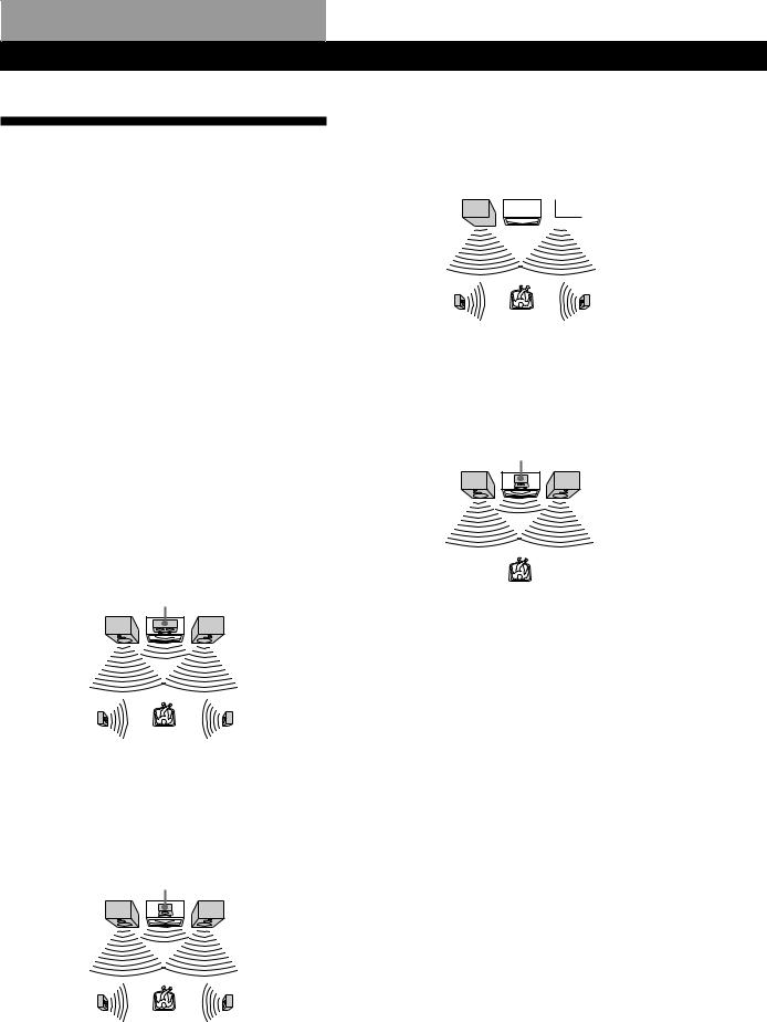
To take advantage of Dolby Pro Logic Surround, you should connect at least one pair of rear speakers and/ or one centre speaker, plus a TV and a VCR. Also, to enjoy a full effect, you need to select the appropriate centre mode (WIDE, NORMAL, PHANTOM, or 3 CH LOGIC modes) on the amplifier, according to your speaker system.
WIDE mode
Select this mode if you have front and rear speakers and a large centre speaker. With this mode, you can take full advantage of Dolby Surround sound.
Centre speaker
Front speaker (L) |
Front speaker (R) |
Rear speaker (L) |
Rear speaker (R) |
NORMAL mode
Select this mode if you have front and rear speakers and a small centre speaker. Since a small speaker cannot produce enough bass, the bass sound of the centre channel is output from the front speakers.
Centre speaker
Front speaker (L) |
Front speaker (R) |
Rear speaker (L) |
Rear speaker (R) |
PHANTOM mode
Select this mode if you have front and rear speakers but no centre speaker. The sound of the centre channel is output from the front speakers.
Front speaker (L)  Front speaker (R)
Rear speaker (L) |
Rear speaker (R) |
3 CH LOGIC mode
Select this mode if you have front and centre speakers but no rear speakers. The sound of the rear channel is output from the front speakers to let you experience some of the surround sound without using rear speakers.
Centre speaker
Front speaker (L) |
Front speaker (R) |
18GB
Dolby Pro Logic Surround Setup
Adjusting the Speaker Volume
To enjoy Dolby Pro Logic Surround sound, select the appropriate centre mode. Then adjust the volume of each speaker using the test tone that the amplifier provides. The test tone feature lets you set the volume of your speakers to the same level. (If all of your speakers have equal performance, you do not have to adjust the speaker volume.)
Using the remote lets you adjust the volume level from your listening position.
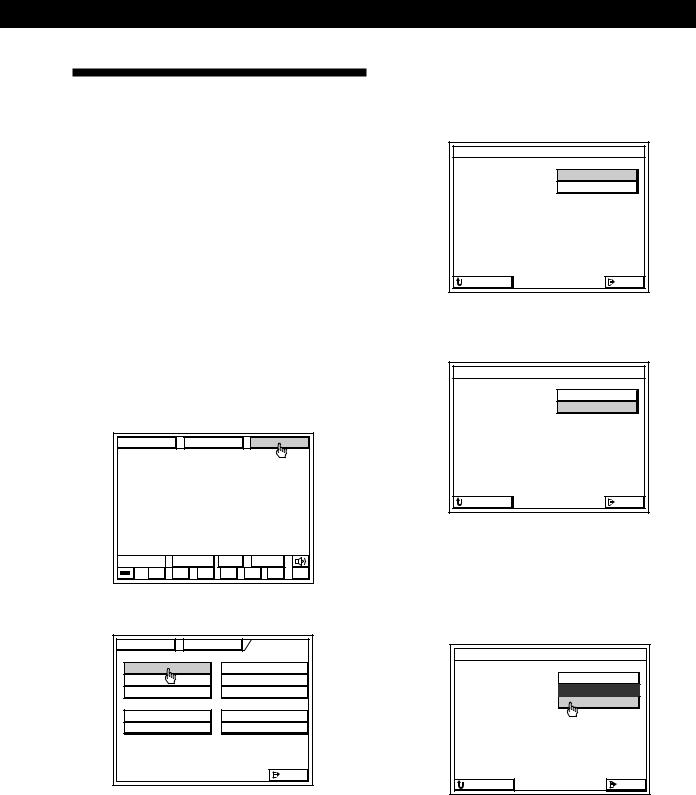
1Click SOUND in the main menu.
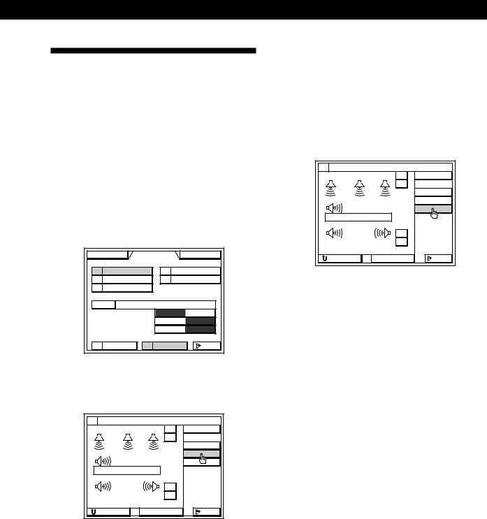
2Click PRO LOGIC, then click SUR.
FUNCTION |
SOUND |
SETUP |
||
PRO LOGIC |
SPORTS |
|||
MOVIE |
|
GAME |
||
MUSIC |
|
|
|
|
MODE |
PRO LOGIC |
|
|
|
SOUND FIELD |
|
O N |
OFF |
|
BASS BOOST |
|
O N |
OFF |
|
DIRECT PASS |
|
O N |
OFF |
|
TONE |
|
SUR |
EXIT |
|
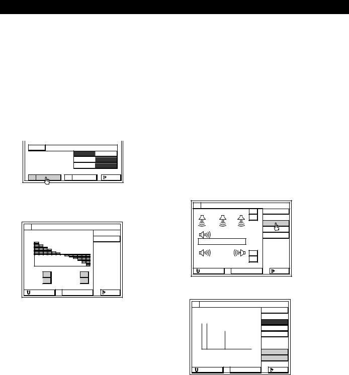
3Click C MODE repeatedly to display the centre mode appropriate for your speaker system (see page 18).
SURROUND EDIT |
|
||
CENTER : |
0 dB |
+ |
LEVEL |
|
|
– |
DELAY |
|
|
|
|
|
|
|
C MODE |
WOOFER |
|
TEST |
|
NORMAL |
|
|
|
|
|
+ |
|
REAR : |
0 dB |
– |
|
RETURN |
STANDARD |
EXIT |
|
4 Click TEST.
You will hear a test tone from the speakers in the following order. The speaker emitting the test tone is shown in red on the SURROUND EDIT menu.
WIDE, NORMAL: Front (left) nCentre n Front (right) nRear
PHANTOM: Front (left and right) nRear
3CH LOGIC: Front (left) nCentre nFront (right)
SURROUND EDIT |
|
||
CENTER : |
0 dB |
+ |
LEVEL |
|
|
– |
DELAY |
|
|
|
|
|
|
|
C MODE |
WOOFER |
|
TEST |
|
NORMAL |
|
|
|
|
|
+ |
|
REAR : |
0 dB |
– |
|
RETURN |
STANDARD |
EXIT |
|
5Adjust the volume levels so that you hear the test tone from each speaker at the same volume level when you are in your listening position:
•Click CENTER + or – to adjust the level of the centre speaker from –15.0 dB to +10.0 dB (1 dB/steps).
During this adjustment, the test tone is emitted from the centre speaker.
•Click REAR + or – to adjust the level of the rear speakers from –15.0 dB to +10.0 dB (1 dB/ steps).
During this adjustment, the test tone is emitted from both speakers simultaneously.
6Click TEST when you are done adjusting. The test tone is turned off.
To return to the main menu
Click EXIT.
To return to a previous menu
Click RETURN.
zYou can adjust all speakers at one time
Use VOL +/– on the remote.
zYou can increase the output level of the rear speakers
You can raise the output of the rear speakers by 5 dB. When turning on the receiver, press POWER and MODE simultaneously to display “GAIN UP”. To return the output level to normal, repeat this procedure to display “GAIN NORMAL”.
19GB
Playback/Recording
Selecting a Component
You can listen to or watch a connected component by clicking on the component in the on-screen display.
Before you begin, make sure you have:
•Registered the IR codes for the connected components (see pages 13 to 17).
•Turned MASTER VOL on the front panel to the leftmost position (0) to avoid damaging your speakers.
•Set the Auto Play function to ON. (The factory setting is ON, see page 30.)
•Selected the appropriate speaker system (see page 8).
•Set BALANCE on the front panel to the centre position.
1Press the button on the remote once or twice to turn on the amplifier.
The TV turns on automatically, and the main menu appears. If the TV does not turn on automatically, see pages 13 to 14 to register your TV.
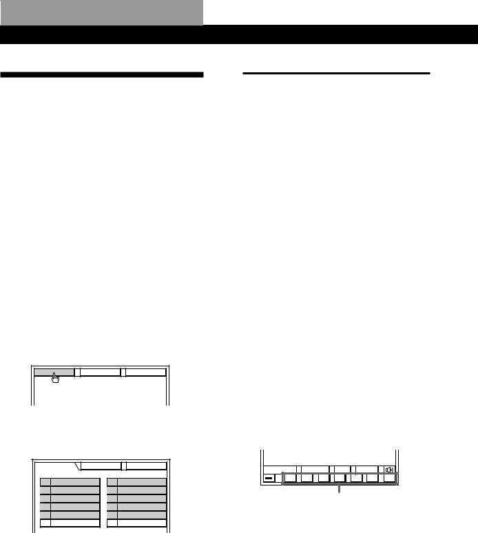
2Click FUNCTION in the main menu.
FUNCTION |
SOUND |
SETUP |
3Click the component you want.
The control buttons appear, then the component turns on and starts playing automatically.
FUNCTION |
SOUND |
SETUP |
VIDEO 1 |
|
TAPE |
VIDEO 2 |
|
DAT / MD |
VIDEO 3 |
|
CD |
L D / DVD |
|
TUNER |
SATL |
|
PHONO |
MACRO 1 |
|
MACRO 2 |
To listen to or watch |
Click*1 |
TV programmes*2 or video tapes |
VIDEO 1, VIDEO 2 |
|
or VIDEO 3 |
|
|
Laser Discs (LD) or DVD |
LD/DVD |
|
|
Satellite broadcasts |
SATL |
|
|
Digital Audio Tapes (DAT) or |
DAT/MD |
MiniDiscs (MD) |
|
|
|
Compact Discs (CD) |
CD |
|
|
Radio programmes |
TUNER |
|
|
Records |
PHONO*3 |
|
|
Analog audio tapes |
TAPE |
|
|
*1 If you connect the component to jacks other than those specified in the table, click the appropriate one according to your connection (e.g., If you connect the LD player to the VIDEO 3 jacks, click VIDEO 3 to watch the LD).
*2 For details about watching TV programmes, see page 21.
*3 Control buttons do not appear when you select PHONO.
4Use VOL + or – on the remote to adjust the volume.
To adjust the volume of the TV's speakers, use the volume control on the TV.
To operate the selected component, click the control buttons. For details of the functions of the control buttons, see the instructions of the selected component. To display other control buttons for the selected component, click SUB.
|
INPUT |
SUB |
USER |
|
0 |
( ) |
p |
P = |
+ |
Control buttons
20GB
Playback/Recording
To turn off the selected component
Click  in the bottom left corner. To turn on the component, follow steps 1 to 3.
To turn off all components
Press ALL OFF on the remote control.
To mute the sound
Click  . The icon changes to
  . “MUTING” appears in the display on the front panel. To turn the sound back on, click on the icon again.

 To listen to decoded Dolby Digital (AC-3) programme sources
Click FUNCTION, then click 5.1 INPUT.
The video signal from the LD/DVD VIDEO IN jack is automatically paired with the audio signals from the 5.1 INPUT jacks. When set to this mode, the audio signals bypass the amplifier‘s sound fields. To customize the sound of the 5.1 INPUT, use the controls on your Dolby Digital (AC-3) decoder.
To listen to the analog audio signals input to the LD/ DVD AUDIO (L and R) jacks, select LD/DVD from the FUNCTION menu.

 You can play video and audio components at the same time
Play a video component you want, then play audio component. Make sure the AUTO PLAY function is set to off (see page 30).
Notes
•Components of the same type (e.g., Sony LD player) will be controlled simultaneously by the on-screen controls.
•If a component does not respond, it may be because IR codes from the IR emitter are not fully reaching the component. In this case, connect the extra IR repeater (supplied) and position it facing the component (see “Infrared (IR) Repeater Hookups” on page 6). If the IR repeater is already connected, change the position of the IR repeater or programme source.
•When 5.1 INPUT is selected, sound fields cannot be selected or edited.
Watching TV or Video
Programmes
Use the TV tuner built-in to the VCR to watch TV programmes; otherwise, the on-screen display will change to a TV programme when you switch channels. Also, set the VCR’s TV tuner to skip channels where there is no broadcast so that an image is always displayed on the TV screen; otherwise, the on-screen display will be distorted.
Before you begin, make sure you have:
•Connected your TV and VCR to the amplifier (see pages 8 to 9).
1Select the appropriate VCR component (e.g., VIDEO 2).
FUNCTION |
SOUND |
SETUP |
VIDEO 1 |
|
TAPE |
VIDEO 2 |
|
DAT / MD |
VIDEO 3 |
|
CD |
L D / DVD |
|
TUNER |
SATL |
|
PHONO |
MACRO 1 |
|
MACRO 2 |
2 Click CH + or – to select the channel you desire.
|
CH – + |
SUB |
USER |
|
0 |
( ) |
p |
P |
REC |
If the Auto Play function is set to on (page 30)
Be sure to click pto stop playback from the VCR before clicking CH + or –.
To change the video input of a Sony VCR
Click SUB, then click INPUT.
To switch the screen size when using a wide TV monitor
Click  repeatedly to select the screen size you desire.
•For non-Sony TVs : You must register the IR code for the wide TV mode button on your TV’s remote (see pages 13 and 14).
21GB
Playback/Recording
Recording
You can control both playback and recording components using the amplifier's on-screen display. If necessary, see the instructions of your recording component.
pRecording to audio tape or MD
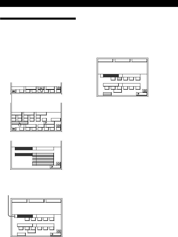
1Click FUNCTION in the main menu.
2Click the playback component you want (e.g., CD).
3 |
Click SUB. |
|
|
|
|
|
|
|
|
|
|
|
INPUT |
SUB |
USER |
|
|||
|
|
0 |
( |
) |
p |
|
P |
= |
+ |
4 |
Click REC EDIT. |
|
|
|
|
|
|
||
|
DISC |
|
TRACK |
D. SKIP |
|
|
|||
|
1 |
2 |
3 |
4 |
5 |
|
|
|
|
|
6 |
7 |
8 |
9 |
10/0 |
>10 |
ENTER |
||
|
REC EDIT |
|
|
|
|
EXIT |
|
||
|
|
|
INPUT |
SUB |
USER |
|
|||
|
|
0 |
( |
) |
p |
|
P |
= |
+ |
5 Click a recording component (e.g., TAPE).
PLAYER |
CD |
RECORDER |
VIDEO 1 |
|
VIDEO 2 |
|
DAT/MD |
|
TAPE |
|
EXIT |
The control buttons for both components appear. “PLAYER” for the playback component, and “RECORDER” for the recording component. The arrow indicates the operative component.
arrow |
|
|
|
|
|
FUNCTION |
|
SOUND |
|
SETUP |
|
/ PLAYER |
|
|
CD |
|
|
|
0 |
( |
) |
p |
P |
RECORDER |
|
|
TAPE |
|
|
0 |
9 |
( |
) |
p |
P |
|
A |
B |
|
|
|
REC |
|
|
|
|
EXIT |
6Insert a blank tape into the recording component (tape deck, etc.) and adjust the recording level, if necessary.
7Click REC to start recording, then click the play button (() on the PLAYER control. Recording starts. Do not click any RECORDER controls while recording. This will cut off the source being recorded.
FUNCTION |
|
SOUND |
|
SETUP |
|
/ PLAYER |
|
|
CD |
|
|
|
0 |
( |
) |
p |
P |
RECORDER |
|
|
TAPE |
|
|
0 |
9 |
( |
) |
p |
P |
|
A |
B |
|
|
|
REC |
|
|
|
|
EXIT |
To stop recording
Click the recording component‘s pcontrol.
To control the recorder after recording
Click RECORDER. RECORDER becomes the operative component and you can use the RECORDER controls to rewind and playback the recording (etc.).
Click PLAYER to operate the playback component.
To return to the main menu
Click EXIT.
Notes
•If you leave the REC EDIT menu by clicking FUNCTION, SOUND, or EXIT, recording continues, but control returns to the PLAYER side, even if you previously clicked RECORDER.
•Some tape decks require that you press the rREC and ( buttons simultaneously to start recording. To perform one-button recording from the on-screen display, be sure to record the recording signal as shown in steps 1 to 7 of “Registering IR codes” (pages 15 to 16).
•Sound input through the 5.1 INPUT jacks cannot be recorded on a recording component.
•When you record on a component connected to the DAT/ MD REC OUT or TAPE REC OUT jacks, sound adjustments do not affect the recording.
22GB
Playback/Recording
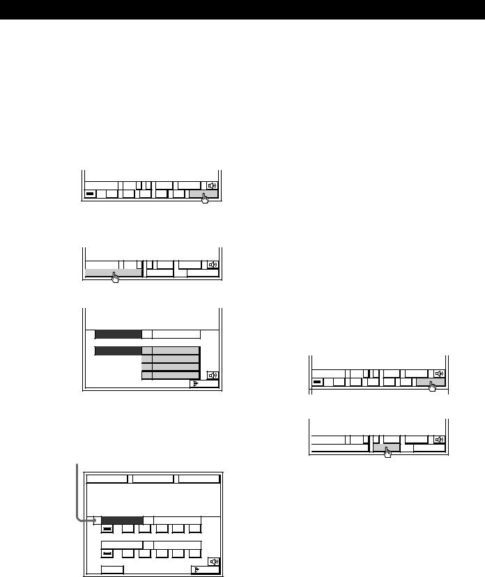
pRecording other components to video tape
1 |
Click FUNCTION in the main menu. |
|||||
2 |
Click the video playback component you want |
|||||
|
(VCR 1, VCR 2, LD/DVD, etc.). |
|||||
3 |
Click REC. |
|
|
|
|
|
|
(If you selected LD/DVD or SATL in step 2 click |
|||||
|
SUB.) |
|
|
|
|
|
|
|
CH – |
+ |
SUB |
USER |
|
|
0 |
( |
) |
p |
P |
REC |
4 |
Click REC EDIT. |
|
|
|
|
|
|
(If you selected LD/DVD or SATL in step 2, click |
|||||
|
REC EDIT in the sub menu.) |
|
|
|||
|
|
CH – + |
SUB |
|
USER |
|
|
REC EDIT |
|
REC |
|
CANCEL |
|
5 |
Click a recording component (e.g., VIDEO 2). |
|||||
PLAYER |
VIDEO 1 |
RECORDER |
VIDEO 1 |
|
VIDEO 2 |
|
DAT/MD |
|
TAPE |
|
EXIT |
The control buttons for both components appear. “PLAYER” for the playback component, and “RECORDER” for the recording component. The arrow indicates the operative component.
arrow |
|
|
|
|
FUNCTION |
SOUND |
SETUP |
||
/ PLAYER |
|
|
VIDEO 1 |
|
0 |
( |
) |
p |
P |
RECORDER |
|
|
VIDEO 2 |
|
0 |
( |
) |
p |
P |
REC |
|
|
|
EXIT |
6Insert a blank tape into the recording component (VCR, etc.) and adjust the recording level, if necessary.
7Click REC to start recording, then click the play button (() on the PLAYER control. Recording starts. Do not click any RECORDER controls while recording. This will cut off the source being recorded.
To stop recording
Click the recording component‘s pcontrol.
To control the recorder after recording
Click RECORDER. RECORDER becomes the operative component and you can use the RECORDER controls to rewind and playback the recording (etc.).
Click PLAYER to operate the playback component.
To return to the main menu
Click EXIT.
pRecording TV programmes to video tape
1Click FUNCTION in the main menu and select a VCR 1 or 2.
2Tune in the TV programme on your video deck.
3Click REC.
CH – + |
SUB |
USER |
0 ( ) |
p |
P REC |
4 Click REC again to start recording.
CH – + |
SUB |
USER |
REC EDIT |
REC |
CANCEL |
23GB

Sound Adjustment
Using the Pre-programmed Sound Fields
The sound fields let you select a sound characteristic to enhance the type of programmes or music you are listening to. To make the most out of this feature, we recommend that you connect centre and/or rear speakers.
Sound fields
Genre |
Mode |
Surround effect |
|
|
|
PRO LOGIC*1 |
PRO LOGIC |
Decodes programmes processed with Dolby Surround. |
|
|
|
|
ENHANCED PRO LOGIC |
Additional output from rear speakers when decoding Dolby Surround |
|
|
programmes. |
|
|
|
MOVIE |
CINEMA STUDIO A |
Reproduces the sound characteristics of the Sony Pictures Entertainment “Cary |
|
|
Grant Theatre” cinema production studio. |
|
|
|
|
CINEMA STUDIO B |
Reproduces the sound characteristics of the Sony Pictures Entertainment “Kim |
|
|
Novak Theatre” cinema production studio. |
|
|
|
|
THEATER |
Adds acoustic reflections of a theatre to decoded Dolby Surround signals. |
|
|
|
|
NIGHT THEATER |
Compresses the dynamic range for listening at low volume levels. |
|
|
|
|
MONO MOVIE |
Creates a theatre-like environment from movies with monaural soundtracks. |
|
|
|
MUSIC |
SMALL HALL |
Reproduces the acoustics of a rectangular concert hall. Ideal for soft acoustic sounds. |
|
|
|
|
LARGE HALL |
|
|
|
|
|
JAZZ CLUB |
Reproduces the acoustics of a jazz club. |
|
|
|
|
LIVE HOUSE |
Reproduces the acoustics of a rock and roll club. |
|
|
|
|
ACOUSTIC*2 |
Reproduces normal 2-channel stereo with equalization (TONE). |
|
|
|
SPORTS |
STADIUM |
Reproduces the feeling of a large open-air stadium. Great for electric sounds. |
|
|
|
GAME |
GAME |
Obtains maximum audio impact from video game software. |
|
|
|
*1 If you select PRO LOGIC, be sure to adjust the volume level of the centre and/or rear speakers to get the most out of the Dolby Pro Logic Surround Sound (see pages 18 and 19).
*2 If you select ACOUSTIC, the hookups of the centre and/or rear speakers are unnecessary.
24GB
Selecting the sound fields
1While playing a component, click SOUND in the main menu.
FUNCTION |
|
SOUND |
|
SETUP |
||
|
INPUT |
SUB |
USER |
|
||
0 |
( |
) |
p |
P |
= |
+ |
2Click a sound field genre, then click MODE repeatedly until the mode you want appears. See the “Sound fields” chart on page 24.
FUNCTION |
SOUND |
SETUP |
||
PRO LOGIC |
SPORTS |
|||
MOVIE |
|
GAME |
||
MUSIC |
|
|
|
|
MODE |
PRO LOGIC |
|
|
|
SOUND FIELD |
|
O N |
OFF |
|
BASS BOOST |
|
O N |
OFF |
|
DIRECT PASS |
|
O N |
OFF |
|
TONE |
|
SUR |
EXIT |
|
To turn off the sound fields
Click SOUND FIELD OFF.
zYou can adjust the bass sound or listen to the music directly in the SOUND FIELD SELECT menu
To increase the bass sound, click BASS BOOST ON. To listen to the music without any audio effects, click DIRECT PASS ON. Click OFF to cancel. Even if you set SOUND FIELD to OFF, these functions are effective.
Sound Adjustment
Customizing the Sound Fields
Each sound field is composed of a tone parameter (bass/treble) and surround sound parameters — variables of sound that create the sound image. You can customize the sound fields by adjusting some of the sound parameters (tone and/or surround sound parameters) to suit your listening situation.
Also, since this amplifier uses Digital Signal Processing (DSP), you can adjust the sound parameters electronically. DSP automatically converts analog audio signals to digital, which lets you adjust the sound with virtually no degradation in sound quality.
Once you customize the sound fields, they are stored in memory unless the amplifier is unplugged for about two weeks. To change a customized sound field, make new adjustments to the sound field.
Adjustable sound parameters
|
|
|
|
|
|
|
|
C STUDIO B |
TONE |
EFFECT |
REAR |
CENTER DELAY |
|
|
THEATER |
|||||
|
N THEATER |
|||||
|
MONO MOVIE |
|||||
MUSIC |
S HALL |
|||||
|
L HALL |
|||||
|
JAZZ CLUB |
|||||
|
LIVE HOUSE |
|||||
|
ACOUSTIC |
|||||
SPORTS |
STADIUM |
|||||
GAME |
GAME |
|||||
GENRE |
MODE |
|||||
PRO LOGIC |
PRO LOGIC |
|
|
1) |
2) |
|
|
ENHANCED |
|
|
1) |
2) |
|
|
PRO LOGIC |
|
|
|
|
|
MOVIE |
C STUDIO A |
|
|
1) |
2) |
|
|
|
|
|
1) |
2) |
|
|
|
|
|
1) |
2) |
|
|
|
|
|
|
|
|
1)Adjustable only when the centre mode is set to PHANTOM, NORMAL, or WIDE (see page 18).
2)Adjustable only when the centre mode is set to 3 CH LOGIC, NORMAL, or WIDE (see page 18).
Notes
•To get the most out of the PRO LOGIC sound fields, also see the chapter “Dolby Pro Logic Surround Setup” on page 18.
•The EFFECT parameter allows you to adjust the overall presence of the sound field.
(continued)
25GB
Sound Adjustment
Adjusting the tone parameter
Adjust the tone (bass or treble) of the front, centre and rear speakers for optimum sound. You can adjust the tone of all sound fields.
1While playing a component, click SOUND in the main menu.
2Click a sound field genre, then click MODE repeatedly until the mode you want appears.
3Click TONE.
MODE THEATER |
|
|
SOUND FIELD |
O N |
OFF |
BASS BOOST |
O N |
OFF |
DIRECT PASS |
O N |
OFF |
TONE |
SUR |
EXIT |
4Click BASS + or – to adjust the level of the low frequencies and click TREBLE + or – to adjust the level of the high frequencies.
|
|
TONE EDIT |
|
+10 dB |
-10 dB |
FLAT |
|
+10 |
|
|
|
-10 |
|
|
|
BASS |
+ |
TREBLE + |
|
|
– |
– |
|
RETURN |
STANDARD |
EXIT |
|
To start adjustment with a flat equalizer curve
Click FLAT.
To reset the tone to the factory settings
Click STANDARD.
Note
You may hear some noise as you adjust the parameters.
Adjusting the delay time
The delay time is the time lag between the surround sound output from front and rear speakers. You can make the surround sound more effective by delaying the output from the rear speakers. You can select between three different delay times: 15ms, 20ms, and 30ms. For example, if you have placed the rear speakers in a large room or apart from your listening position, you might want to shorten the delay time.
Delay time adjustment is only available for the PRO LOGIC genre.
1Start playing a component encoded with Dolby surround sound, then click SOUND in the main menu to display the SOUND FIELD SELECT menu.
2Click PRO LOGIC, then click SUR.
3Click DELAY.
SURROUND EDIT |
|
||
CENTER : |
0 dB |
+ |
LEVEL |
|
|
– |
DELAY |
|
|
|
|
|
|
|
C MODE |
WOOFER |
|
TEST |
|
NORMAL |
|
|
|
|
|
+ |
|
REAR : |
0 dB |
– |
|
RETURN |
STANDARD |
EXIT |
|
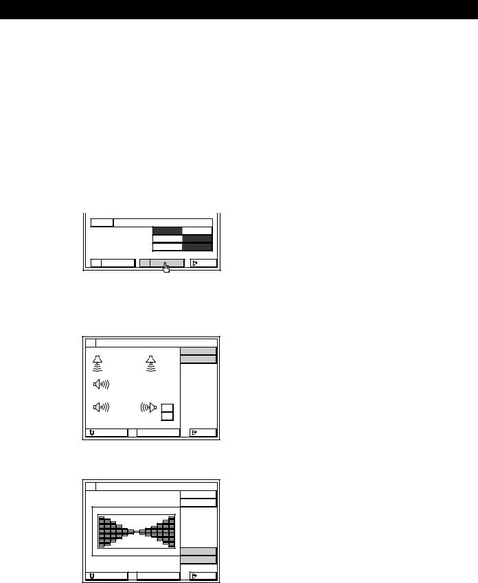
4 Click SHORT or LONG to adjust the delay time.
SURROUND EDIT |
|
|
|
|
LEVEL |
TIME : |
20 ms |
|
|
|
DELAY |
|
|
C MODE |
|
|
TEST |
15 |
30 |
LONG |
|
|
SHORT |
RETURN |
STANDARD |
EXIT |
To reset the delay time to the factory settings
Click STANDARD.
26GB
Sound Adjustment
Adjusting the effect or speaker levels
Adjust the effect and speaker level parameters to fit your listening situation. See the chart “Adjustable sound parameters” on page 25 for parameters you can adjust in each sound field.
1While playing a component, click SOUND in the main menu to display the SOUND FIELD SELECT menu.
2
3
Click a sound field genre, then click MODE repeatedly until the mode you want appears.
Click SUR.
MODE THEATER |
|
|
SOUND FIELD |
O N |
OFF |
BASS BOOST |
O N |
OFF |
DIRECT PASS |
O N |
OFF |
EQ |
SUR |
EXIT |
4Click the icon for the parameter you want to adjust.
The parameter chart for your selection appears. See the next page for details of each adjustment.
SURROUND EDIT |
|
|
|
|
LEVEL |
|
|
EFFECT |
WOOFER |
|
|
|
+ |
|
REAR : |
+10 dB – |
|
RETURN |
STANDARD |
EXIT |
5Click an adjustment icon (+ / – , UP/DOWN, SHORT, LONG, etc.,) to adjust the parameter.
SURROUND EDIT |
|
|
|
|
LEVEL |
SUR EFFECT |
EFFECT |
|
|
|
UP |
|
|
DOWN |
RETURN |
STANDARD |
EXIT |
To reset all parameters (except for the delay time) of the current sound field to the factory settings.
Click STANDARD.
27GB

Additional Operations and Settings
Registering Desired Components (User IR setting)
Use the USER IR CODE SETTING menu to register any IR codes that could not be registered in “Registering Audio and Video Components” on page 15. By registering User IR codes, you can control a variety of appliances (such as air conditioners) as well as audio/ video components. You can register up to 20 User IR codes.
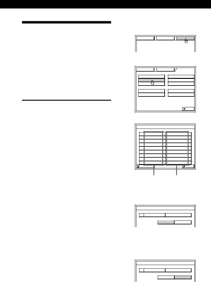
1Click SETUP in the main menu to display the SETUP menu, then click USER IR.
FUNCTION |
SOUND |
SETUP |
|
TV |
SET |
FUNC |
INDEX |
IR |
SET |
CD |
INDEX |
USER IR |
TUNER |
INDEX |
|
AUTO START |
SLEEP TIMER |
||
MACRO PLAY |
OSD SETUP |
||
2Click A B C D to select a User IR code page, then click INDEX.
USER IR CODE SETTING
USER |
A1 |
|
A B C D |
|
USER |
A2 |
|
|
|
USER |
A3 |
|
INDEX |
|
USER |
A4 |
|
START |
|
USER |
A5 |
|
|
|
3Create a name for the IR code by clicking each character. The name is automatically stored. To enter a space, click the space bar. To switch between upper and lower case letters, click CAPS. If you made a mistake, click ?or /to move the cursor to the character to be changed, then click the correct character.
|
USER IR CODE SETTING |
|
|
||||
|
|
|
|
|
B |
|
b |
A |
B |
C |
D |
E |
1 |
2 |
3 |
F |
G |
H |
I |
J |
4 |
5 |
6 |
K |
L |
M |
N |
O |
7 |
8 |
9 |
P |
Q |
R |
S |
T |
/ |
0 |
* |
U |
V |
W |
X |
Y |
Z |
– |
+ |
CAPS |
|
|
|
|
|
|
|
RETURN |
|
|
|
|
|
EXIT |
|
Space bar
4Click RETURN to go back to the USER IR CODE SETTING menu, then repeat steps 2 to 4 until you enter the names of all the IR codes you want to register.
5Click the name of the first IR code.
USER IR CODE SETTING
LIGHT 1 |
A B C D |
|
LIGHT 2 |
|
|
LIGHT 3 |
INDEX |
|
LIGHT |
4 |
START |
LIGHT |
5 |
|
6Cover the IR sensor on the respective component to prevent accidental operation during the registration procedure.
7Click START.
When “PUSH YOUR REMOTE” appears on the TV screen, press the button you want to register.
USER IR CODE SETTING |
|
|
LIGHT 1 |
A B C |
D |
LIGHT 2 |
|
|
LIGHT 3 |
INDEX |
|
LIGHT 4 |
START |
|
LIGHT 5 |
|
|
|
CODE CLEAR |
|
RETURN |
|
EXIT |
IR sensor
Your component's remote
When registering the IR code, be sure to do the following; otherwise, the IR code may not be registered correctly.
•Point the remote at the IR sensor on the
amplifier from a distance of less than 1 inch (3 cm).
•Hold down the button on the remote for about 2 or 3 seconds until the “RECEIVING” display switches to “RELEASE YOUR REMOTE”.
•Keep the remote pointed horizontally at the IR sensor until the code is registered.
To register a specific IR code
Click the button where the IR code was registered, then click START.
28GB
Additional Operations and Settings
Notes
•If the mains lead is disconnected for about two weeks, the registered IR codes will be cleared. “ALL CLEAR!” will appear on the TV screen the next time you turn on the amplifier.
•The power switch on some air conditioners use two independent IR codes, even when there is only one switch. If you cannot turn the air conditioner off with the IR code registered for the on/off switch, repeat the procedure and register the on and off IR codes separately.
•The amplifier may not be able to register IR codes with special waveforms produced on some remote controls.
Erasing IR codes
Click CODE CLEAR in the USER IR CODE SETTING menu.
•To erase a specific IR code
1Click SINGLE IR CODE CLEAR. “SELECT CLEAR CODE KEY” appears.
2Click the button you want to clear. “Are you sure?” appears.
3Click YES to erase the code. “CODE CLEAR!” appears. To cancel erasing, click NO.
To erase another code, repeat steps 2 and 3.
•To erase all the User IR codes
1Click USER IR CODE CLEAR. “Are you sure?” appears.
2Click YES to erase the codes. “CODE CLEAR!” appears. To cancel erasing, click NO.
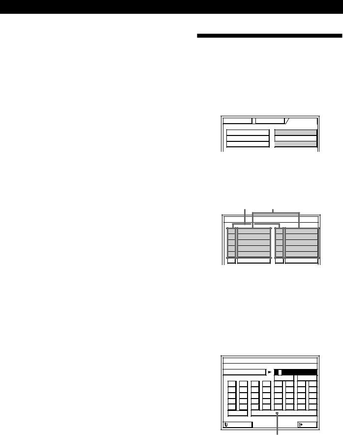
Indexing
The Index functions let you specify icons for each function button and names up to 8 characters long for each function button and preset radio station.
1Click SETUP in the main menu to display the SETUP menu, then click FUNC INDEX or TUNER INDEX.
FUNCTION |
SOUND |
SETUP |
|
TV |
SET |
FUNC |
INDEX |
IR |
SET |
CD |
INDEX |
USER IR |
TUNER |
INDEX |
|
2• For the function buttons (FUNCTION INDEX) 1 Click the icon to be specified.
2 Click the icon you want from the icon menu, then click RETURN.
3 Click the function button to be specified.
Icons |
Function buttons |
FUNCTION INDEX SETTING
VIDEO 1 |
TAPE |
VIDEO 2 |
DAT / MD |
VIDEO 3 |
CD |
L D / DVD |
TUNER |
SATL |
PHONO |
MACRO 1 |
MACRO 2 |
• For the preset radio stations (TUNER INDEX)
1Click LIST TUNER to display the preset list.
2Click ABC to select the page, then select the station to be named.
3Create the new name by clicking each character. The name is stored automatically. To enter a space, click the space bar. If you made a mistake, click ?or /to move the cursor to the character to be changed, then click the correct character.
|
FUNCTION INDEX SETTING |
|
|
||||
|
|
|
|
|
B |
|
b |
A |
B |
C |
D |
E |
1 |
2 |
3 |
F |
G |
H |
I |
J |
4 |
5 |
6 |
K |
L |
M |
N |
O |
7 |
8 |
9 |
P |
Q |
R |
S |
T |
/ |
0 |
* |
U |
V |
W |
X |
Y |
Z |
– |
+ |
CAPS |
|
|
|
|
|
|
|
RETURN |
|
|
|
|
|
EXIT |
|
Space bar
29GB
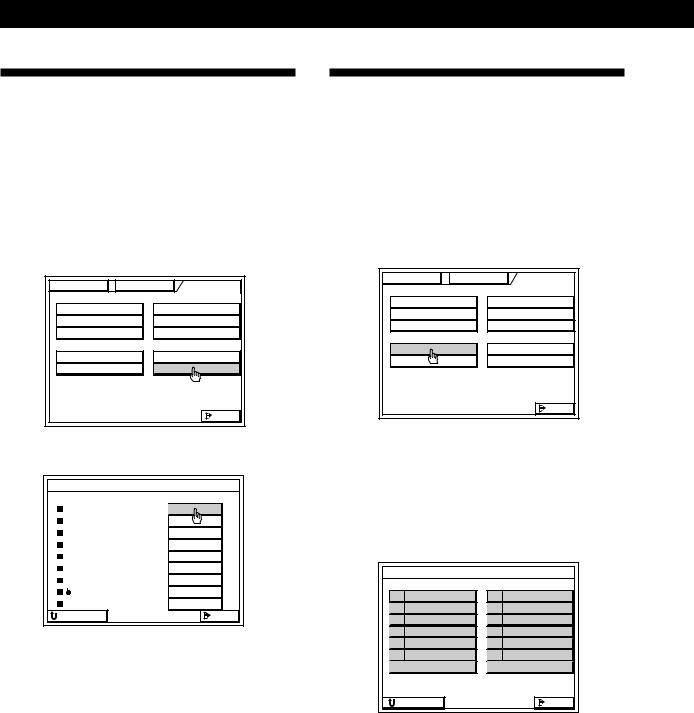
Additional Operations and Settings
Playing Components
Automatically (Auto Play)
The Auto Play function lets you set the amplifier to start playing the components immediately after they are selected from the FUNCTION SELECT menu. The amplifier comes from the factory with Auto Play set to on.
1Click SETUP in the main menu to display the SETUP menu, then click OSD SETUP.
FUNCTION |
SOUND |
SETUP |
|
TV |
SET |
FUNC |
INDEX |
IR |
SET |
CD |
INDEX |
USER IR |
TUNER |
INDEX |
|
AUTO START |
SLEEP TIMER |
||
MACRO PLAY |
OSD SETUP |
||
|
|
|
EXIT |
2 Click AUTO PLAY ON or OFF.
OSD SETUP |
|
|
AUTO PLAY |
ON |
OFF |
IR OUTPUT |
ON |
OFF |
AUTO OSD ERASE |
ON |
OFF |
SEE-THROUGH |
ON |
OFF |
LANGUAGE |
ENGLISH |
|
POINTER ONLY |
SET |
|
DEMO |
START |
|
FEELING |
1 2 3 4 5 |
|
OSD POSITION |
SET |
|
RETURN |
|
EXIT |
Notes
•The Auto Play function does not work when you operate the amplifier from the front panel.
•The amplifier cancels the automatic playback function of components designed to start playing when they are turned on (such as laser disc and CD players). To activate the auto play function, set the amplifier’s Auto Play to on.
Starting a Component
Automatically at Power On
(Auto Start)
The Auto Start function lets you set the amplifier to start playing a specific component immediately whenever you turn on the amplifier.
1Click SETUP in the main menu to display the SETUP menu, then click AUTO START.
FUNCTION |
SOUND |
SETUP |
|
TV |
SET |
FUNC |
INDEX |
IR |
SET |
CD |
INDEX |
USER IR |
TUNER |
INDEX |
|
AUTO START |
SLEEP TIMER |
||
MACRO PLAY |
OSD SETUP |
||
|
|
|
EXIT |
2Click the component you want.
•To start the last-played component automatically when you turn on the amplifier, click LAST.
•To do a macro automatically when you turn on the amplifier, click MACRO 1 or MACRO 2. Be sure that the Auto Play function is set to on.
AUTO START SETTING |
|
VIDEO 1 |
TAPE |
VIDEO 2 |
DAT / MD |
VIDEO 3 |
CD |
L D / DVD |
TUNER |
SATL |
PHONO |
MACRO 1 |
MACRO 2 |
NO SET |
LAST |
RETURN |
EXIT |
To cancel the Auto Start function
Click NO SET in step 2.
Note
A Macro Play setting containing the ALL OFF command cannot be selected for Auto Start.
30GB
 Loading...