


Sony STR-DE415, STR-DE315, STR-D460Z User Manual
SON'Y:
3-859-657-22(2)
FM Stereo
FM-AM Receiver
Operating Instructions
STR-DE515
STR-DE415
STR-DE315
STR-D460Z
STR-D360Z
© 1997 by Sony Corporation
WARNING
To prevent fire or shock
hazard, do not expose
the unit to rain or
moisture.
This symbol is intended to alert the user
to the presence of uninsulated
"dangerous voltage" within the
product's enclosure that may be of
sufficient magnitude to constitute a risk
of electric shock to persons.
This symbol is intended to alert the user
to the presence of important operating
and maintenance (servicing)
instructions in the literature
accompanying the appliance.
IMPORTANT
This equipment has been tested and
found to comply with the limits for a
Class Bdigital device, pursuant to Part
15 of the FCC Rules.
These limits are designed to provide
reasonable protection against harmful
interference in a residential installation.
This equipment generates, uses, and can
radiate radio frequency energy and, if
not installed and used in accordance
with the instructions, may cause
harmful interference to radio
communications. However, there is no
guarantee that interference will not
occur in a particular installation Ifthis
equipment does cause harmtul
interference to radio or television
reception, which can be determined by
turning the equipment off and on, the
user Is encouraged to try to correct the
inter terence by one or more of the
following measures:
2
- Reorient or relocate the recelving
antenna
Increase the separation between the
equipment and receiver
- Connect the equipment into an outlet
on a circuit different from that to
which the receiver is connected
- Consult the dealer or an experienced
radio/TV technician for help.
CAUTION
You are cautioned that any change or
modifications not expressly approved in
this manual could void your authority
to operate this equipment
Note to CATV system installer
This reminder is provided to call the
CATV system installer's attention to
Article 820-40 of the NEC that provides
guidelines for proper grounding and, in
particular, specifios that the cable
ground shall be connected to the
grounding system of the building, as
close to the point of cable entry, as
practical.
Owner's record
The model and serial numbers are
located on the rear of the unit. Record
the serial number in the space provided
below Refer to them whenever you call
upon your Sony dealer regarding this
product
Model No. STR-DE515/BTR-DE415/
STR-DE315/STR-D460Z/
STR-D36OZ
Serial No.
Precautions
On safety
• Should any solid object or liquid fall
into the cabinet, unplug the receiver
and have it checked by qualified
personnel before operating it any
further.
On power sources
• Before operating the receiver, check
that the operating voltage is identical
with your local power supply, The
operating voltage is indicated on the
nameplate at the rear of t]_e receiver¸
• The receiver is not discoonected from
the AC power source (MAINS) as
long as it is connected to the wall
outlet, even if the receiver itself has
been turned off.
• If you are not going to use the
receiver for a long time, be sure to
disconnect the receiver from the wall
outlet. To disconnect the AC power
cord, grasp the plug itself; never pulI
the cord.
• One blade of the plug is wider than
the other for the purpose of safety
and will fit into the wall outlet only
one way If you are unable to insert
the plug fully into the outlet, contact
your dealer. (US model onlyt
• Should the AC power cord need to be
changed, have it done at a qualified
service shop only.
On placement
• Place the receiver in a location with
adequate ventilation to prevent heat
build up and prolong the life of the
receiver.
• Do not place the receiver near heat
sources, or in a place subject to direct
sunlight, excessive dust or
mechanical shock
• Do not place anything on top of the
cabinet that might block the
ventilation holes and cause
malfunctions.
On operation
• Before connectlng uther components,
be sure to turn off and unplug the
recewer
On cleaning
• Clean the cabineb panel and controls
with a soft cloth slightly moistened
with a mild detergent solution. Do
not use any type of abrasive pad,
_,COLirlng powder or solvent such as
alcohol or benzine.
For detailed safety precautions, see the
"IMPORTANT SAFEGUARDS" leaflet.
If you have any question or problem
concerning your receiver, please
consult your nearest Sony dealer.
About This Manual
The instructions in this manua] are for
models STR-DE515, STR-DE415,STR-
DE315, STR- D460Z and STR-D360Z.
Check your model number by looking
at the upper right corner of the front
panel or lower right corner of the
remote. In this manual, the STR-DflSl5
is the model used for illustration
purposes, any difference in operation is
clearly indicated in the text, for
example,
"STR-DE515 only"
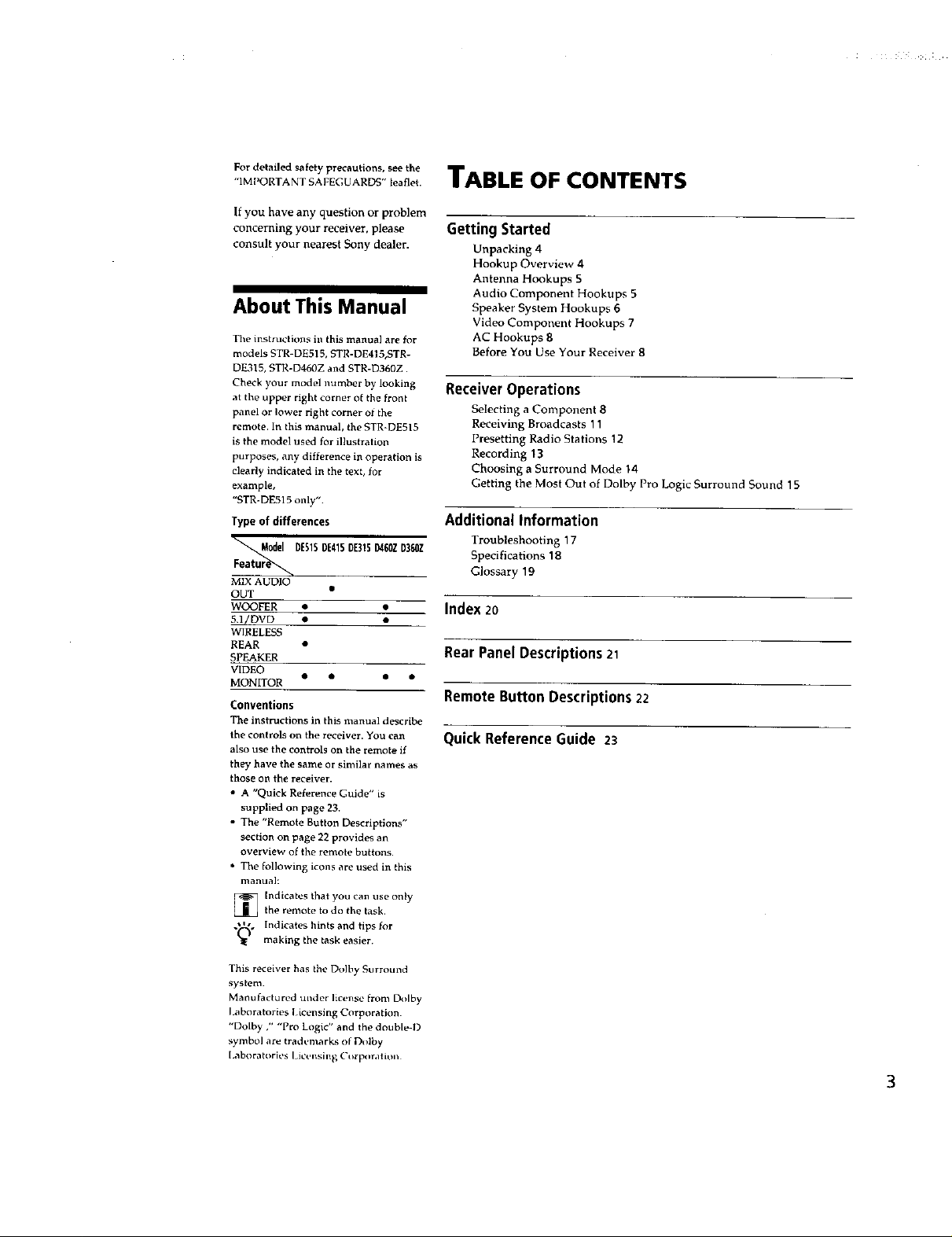
Type of differences
Model D[515DE415DE315_60Z D]_Z
MIX AUDIO
OUT
WOOFER
5,1/DVD :
WIRELESS
REAR •
SPEAKER
VIDEO
MONITOR
Conventions
The instructions in this nlanua] describe
the controls On the receiver. You can
also use the controls on the remote if
they have the same or similar names as
those on the receiver.
• A "Quick Reference Guide" is
supplied on page 23.
• The "Remote Button Descriptions"
section on page 22 provides an
overview of the remote buttons.
• The following icons are used in this
manual:
Indicates that you can use only
] the remote to do the task.
.}._. Indicates hints and tips for
Y
making the task easier
TABLE OF CONTENTS
Getting Started
Unpacking 4
Hookup Overview 4
Antenna Hookups S
Audio Component Hookups 5
Speaker System Hookups 6
Video Component Hookups 7
AC Hookups 8
Before You Use Your Receiver 8
ReceiverOperations
Selecting a Component 8
Receiving Broadcasts 11
Presetting Radio Stations 12
Recording 13
Choosing a Surround Mode _4
Getting the Most Out of Dolby Pro Logic Surround Sound 1 5
Additional Information
Troubleshooting 17
Specifications 18
Glossary 19
Index 20
Rear Panel Descriptions21
Remote Button Descriptions22
QuickReferenceGuide 23
This receiver has the Dolby Surround
system
Manufactured under license from D(_lby
haboratories Licensing Corporation
"Dolby ," "Pro Logic" and the doubleq)
symbol are trademarks of Dt)lby
[.aboratl_ries Licensil_g Cl_rp(_ration
3
Unpacking
Hookup Overview
Check that you received the following items with the
receiverl
• FM wire antenna (1)
• AM loop antenna (1)
• Remote controller (remote) (!)
• Size AA (R6) batteries (2)
Inserting batteries into the remote
Insert two size AA (R6) batteries in accordance with
the + and - markings on the battery compartment,
When using the remote, point it at the remote sensor m
on the receiver.
¢
"_" When to replace batteries
Under normal use, the batteries should last for about 6
months. When the remote no longer operates the
receiver, replace both batteries with new ones.
Notes
• DO not leave the remote in an extremely hot or humid
place.
• Do not use a new battery with an old one
• Do not expose the remote sensor to direct sunlight or
lighting apparatuses. Doing so may cause a malfunction.
• If you don't use the remote/or an extended period of time,
remove the batteries to avoid possible damage from
battery leakage and corrosion.
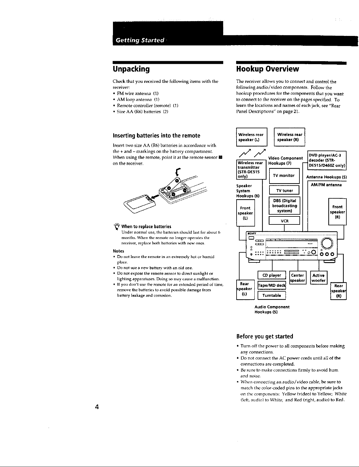
The receiver allows you to connect and control the
following audio/video components. Follow the
hookup procedures for the components that you want
to connect to the receiver on the pages specified. To
learn the locations and names of each jack, see "Rear
Panel Descriptions" on page 2I.
speaker (L) speaker (R)
Wireless rear Wireless rear
JJ
transmitter
Wireless rear Hookups (7)
(STR-DE515
ionly ) TV monitor
Speaker ]
System TV tuner
Hookups (6)
Fm ,t system)
{_C_ID , , ,
_aker _ I
Video Component
broadcasting
/
DVD player/AC-3
decoder (STR-
DES15/D460Z only
Antenna Hookups (5)
AM/FM antenna
°°t
far
ake
Audio Component
Hookups (5)
Beforeyou get started
• Turn off the power to all components before making
any connections
• Do not connect the AC power cords until all of the
connections are completed.
• Be sure to make connections firmly to avoid bum
and noise.
• When connecting an audio/video cable, be sure to
match the color-coded pins to the appropriate jacks
on the components: Yellow (video) to Yellow; White
(left, audio) to White; and Red (right, audio) to Red.
4
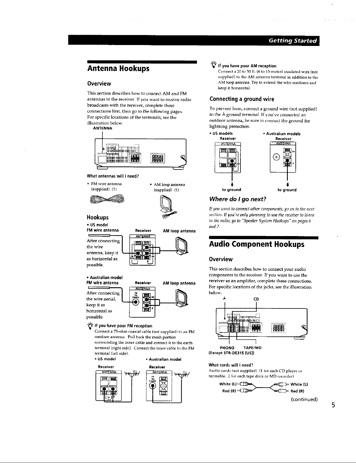
Antenna Hookups
Overview
This section describes how to connect AM and FM
antennas to the receiver. If you want to receive radio
broadcasts with the receiver, complete these
connections first, then go to the following pages.
For specific locations of the terminals, see the
illustration below.
ANTENNA
- i®®
What antennas will I need?
• FM wire antenna * AM loop antenna
(supplied) (1) (supplied) (1)
Hookups
• US model
FM wire antenna Receiver AM loop antenna
"_" If you have poor AM reception
CoiInect a 20 to 50 ft. (6 to 15-meter) insulated wire (not
supplied) to the AM antenna terminal in addition to the
AM loop antenna Try to extend the wire outdoors and
keep it horizontal.
Connectinga ground wire
To prevent hum, connect a ground wire (not supplied)
to the r_ ground terminal. If you've connected all
outdoor antenna, be sure to connect the ground for
lightning protection.
• US models " Australian models
Receiver Receiver
to ground to ground
Where do I go next?
If you want to connect other components, go on to tile next
section. If you're only planning to use the receiver to lis ten
to the nzdio, go to "Speaker System Hookups" on pages 6
attd 7,
• Australian model
FM wire antenna Receiver AM loop antenna
After connecting
the wire aerial,
keep it as
;Ors::b_:al. as
If have
"_" you poor reception
Connect a 75-ohm coaxial cable (not supplied) to an FM
outdoor antenna. Pull back the mesh portion
surrounding the inner cable and connect it to the earth
terminal (right side) Connect the inner cable to the FM
terminal (left side)
• US model • Australian model
Receiver Receiver
FM
Audio Component Hookups
Overview
This section describes how to connect your audio
components to the receiver. If you want to use the
receiver as an amplifier, complete these connections.
For specific locations of the jacks, see the illustration
below,
CD
PHONO TAPE/MD
(Except STR-DE315 (US))
What cords will I need?
Audio cords/not supplied) (/ for each CD player (_r
turntable; 2 for each tape deck or MD recorder)
White (L) _=m_,_z_ White (L)
Red (R) _ _ Red (R)
(continued)
5
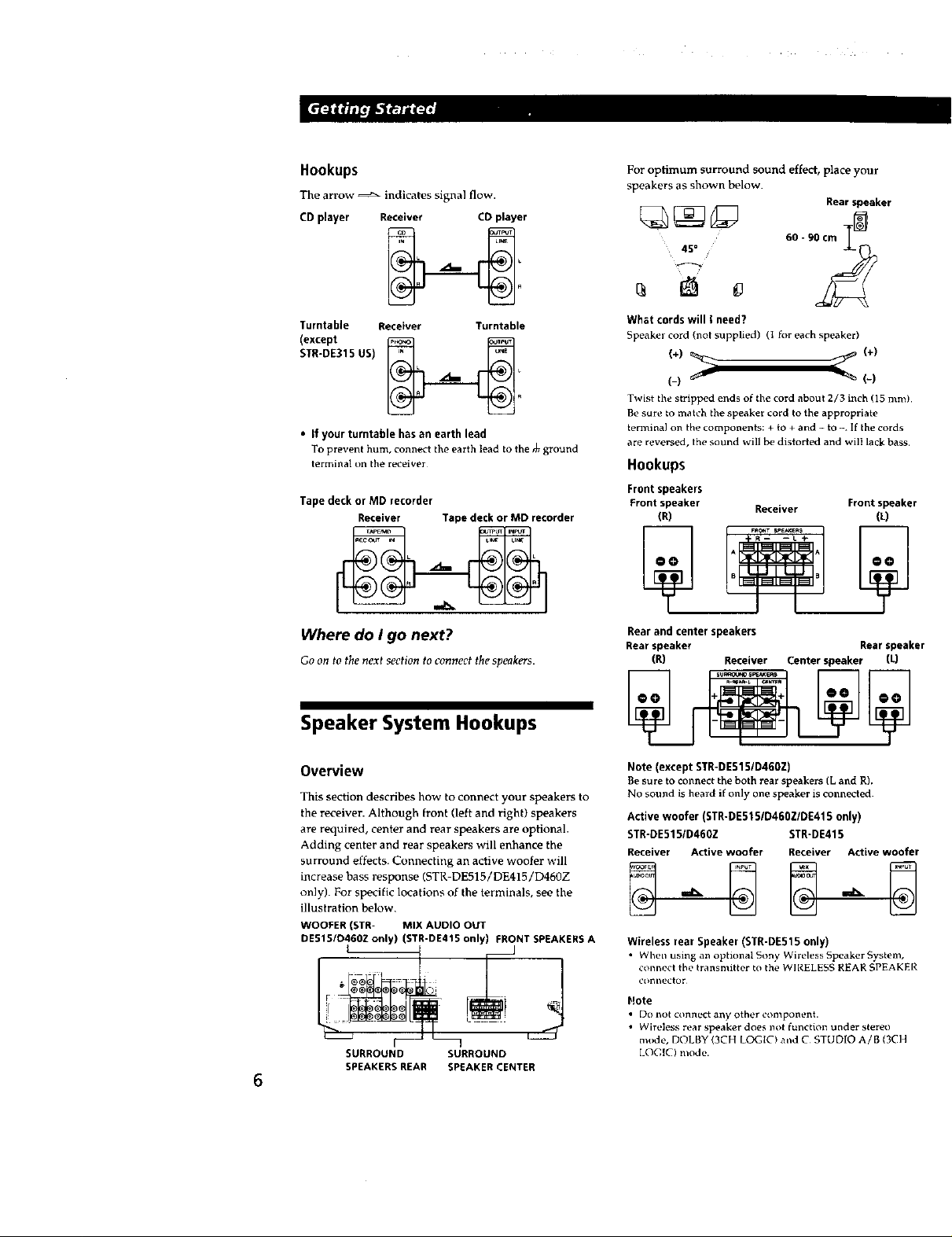
Hookups
The arrow _ indicates signal flow.
CD player Receiver CD player
For optimum surround sound effect, place your
speakers as shown below.
Rear speaker
45 °
60 - 9_
Turntable Receiver Turntable
SIR-DE315 US)
Cexcept
• if your turntable has an earth lead
To prevent hum, connect the earth lead to the _ ground
terminal on the receiver
Tape deck or MD recorder
Receiver Tape deck or MD recorder
Where do I go next?
Go on to the next section to connect the speakers.
Speaker System Hookups
Overview
This section describes how to connect your speakers to
the receiver. Although front (left and right) speakers
are required, center and rear speakers are optional.
Adding center and rear speakers will enhance the
surround effects. Connecting an active woofer will
increase bass response (STR-DE515 / DE415/D460Z
only). For specific locations of the terminals, see the
illustration below.
WOOFER (STR- MIX AUDIO OUT
DE515/D460Z only) (STR-DE415 only) FRONT SPEAKERS A
®® ==
F : @® (D
SURROUND SURROUND
SPEAKERS REAR SPEAKER CENTER
What cordswill I need?
Speaker cord (not supplied) (I for each speaker)
(*) _. _ (+)
(_) _ _ (-)
Twist the stripped ends of the cord about 2/3 inch (15 ram).
Be sure to match the speaker cord to the appropriate
terminal on the components: + to + and - to -. If the cords
are reversed, the sound will be distorted and will lack bass.
Hookups
Front speakers
Front speaker Receiver Front speaker
(R) (h)
R-- --L+
A A
B B
Rear and center speakers
Rear speaker Rear speaker
(R) Receiver Center speaker (L)
Note (except STR-DE5151D460Z)
Be sure to col_nect the both rear speakers (L and R),
No sound is heard if only one speaker is connected.
Active woofer (STR-DESf5/D460ZlDE415only)
STR-DE5151D460Z STR-DE415
Receiver Active woofer Receiver Active woofer
Wireless rear Speaker (STR-DE515 only)
• When using an optional S(my Wireless Speaker System,
connect the transmitter to the WIRELESS REAR SPEAKER
ctmnector
F!ote
• Do not connL_ct any other corllponel_t.
• Wireless rear speaker does Ilot function under stereo
mode, DOLBY (3CH LOGIC) and C STUDIO A/B (3C14
I.OGIC) nlode.
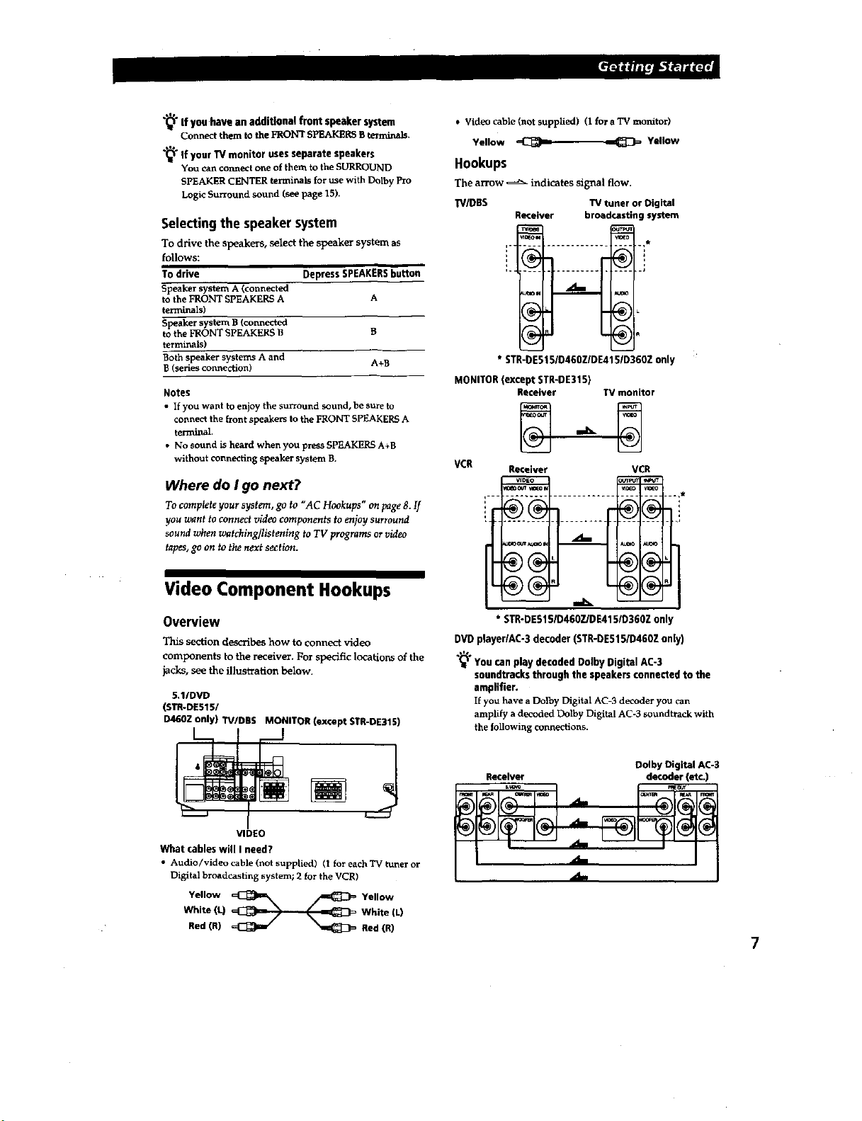
"_lf you have an addifiona front speaker system
Connect them to the FRONT SPEAKERS B te_minab.
";_lf your TV monitor uses separate speakers
You can cormect one of them to the SURROUND
SPEAKER CENTER terminals for use with Dolby pro
Logic Surround sound (see page 15).
Selecting the speaker system
To drive the speakers, select the speaker system as
follows:
To drive Depress SPEAKERSbutton
Speaker system A (connected
to the FRONT SPEAKERS A A
terminals)
Speaker system B (connected
to tEe FRONT SPEAKERS B B
terminals)
Both speaker systems A and
B (series connection) A+B
Notes
• If you want to enjoy the surrOund sound, be sure to
connect the front speakers to the FRONT SPEAKERS A
terminal.
• No sound is heard when you press SPEAKERS A+B
without connecting speaker system B.
Where do I go next?
To complete your system, go to "AC Hookups" on page 8. If
you want to connect video components to enjoy surround
sound when watchingJlistening to TV programs or video
tapes, go on to the next section.
• Video cable (not supplied) (t for a _ monitor)
Yellow =_ Yellow
Hookups
The arrow _ radiates signal flow.
TVIDBS
Receiver broadcasting system
• STR-_SIg/D460Z/DE41_360Z only
MONITOR (except STR-DE315)
VCR
Receiver TV monitor
Receiver VCR
TV tuner or Digital
q
Video Component Hookups
Overview
This section describes how to connect video
components to the receiver. For specific locations of the
jacks, see the illust:caflon below.
5,1/DVD
(STR-DESIS/
D460Z only) TV/DBS MONITOR (except STR-DE31 S)
VIDEO
What cables will I need?
• Audio/video cable (not supplied) (1 for each "IV tuner or
Digital broadcasting system; 2 for the VCR)
Yellow =C_lm_ /m_= Yellow
White (L) _ White (L)
Red (R) =[_]mm / _ Red (R)
• STR-DES15/D460Z/DE415/D360Zonh
DVDplayerlAC-3 decoder(STR-DE515/D460Zonly)
"_" You canplay decodedDolby Digital AC-3
soundttacksthroughthe speakersconnectedto the
amplifier.
If you have a Dolby Digital AC-3 decoder you can
amplify a decoded Dolby Digital AC-3 soundtrack with
the following connections.
Dolby Digital AC-3
Receiver decoder (etc.)
! - I
_L--
7
Where do I go next?
Go otl to thc _w.\'t section1 to conm, ct the AC power cord a_id
colilplete your home thc_tl'r system.
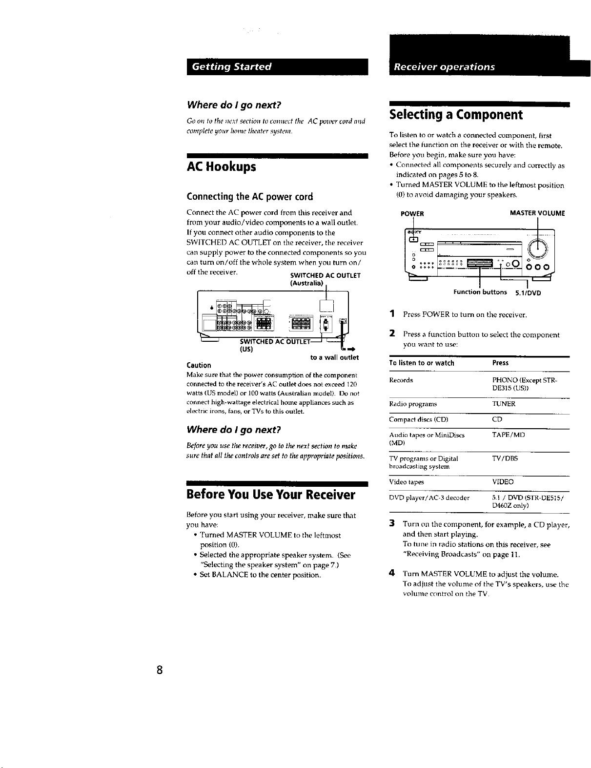
AC Hookups
Connectingthe ACpower cord
Connect the AC power cord from this receiver and
from your audio/video components to a wall outlet.
If you connect other audio components to the
SWITCHED AC OUTLET on the receiver, the receiver
can supply power to the connected components so you
can turn on/off the whole system when you turn on/
off the receiver, SWITCHED AC OUTLET
(Australia)
Selecting a Component
To listen to or watch a connected component, first
select the tunction on the receiver or with the remote.
Before you begin, make sure you have:
• Connected all components securely and correctly as
indicated on pages 5 to 8.
• Turned MASTER VOLUME to the leftmost position
(0) to avoid damaging your speakers.
POWER MASTER VOLUME
Function buttons 5.1/DVD
1 Press POWER to turn on the receiver.
SWITCHED AC OUTLET_ _-
(US) _r. ,._
Caution
Make sure that the power ¢onsun'Lptlon of the component
connected to the receiver's AC outlet does not exceed t 20
watts (US model) or 100 watts (Australian model). Do not
connect high-wattage electrical home appliances such as
electric irons, fans, or TVs to this outlet.
to a wall outlet
Where do I go next?
Before you use the receiver, go to the next section to make
sure that all the controls are set to the appropriate positions.
Before You UseYour Receiver
Before you start using your receiver, make sure that
you have:
• Turned MASTER VOLUME to the leftmost
position (0).
• Selected the appropriate speaker system. (See
"Selecting the speaker system" on page 7.)
• Set BALANCE to the center position.
2 Press a function button to select the component
you want to use:
To listen to or watch Press
Records PHONO (Except STR-
Radio programs TUNER
Compact discs (CD) CD
Audio tapes or MiniDiscs TAPE/MD
(MD)
TV programs or Digital TV/DBS
broadcasting system
Video tapes VIDEO
DVD player/AC-3 decoder 5.I / DVD (STR-DE5IS/
_1 Turn on the component, for example, a CD player,
and then start playing.
To tune in radio stations on this receiver, see
"Receiving Broadcasts" on page 11.
4 Turn MASTER VOLUME to adjust the volume.
To adjust the volume of the TV's speakers, use the
volume control on the TV
DE315 (US))
D460Z only)
8
 Loading...