

Page 1
FM Ster eo
FM-AM Receiver
3-866-967-11(1)
Operating Instructions
STR-DA777ES
1999 by Sony Corporation
Page 2
WARNING
To prevent fire or shock
hazard, do not expose the
unit to rain or moisture.
Do not install the
appliance in a confined
space, such as a bookcase
or built-in cabinet.
For the customers in United States
This symbol is intended to alert the user to
the presence of uninsulated “dangerous
voltage” within the product’s enclosure
that may be of sufficient magnitude to
constitute a risk of electric shock to
persons.
This symbol is intended to alert the user to
the presence of important operating and
maintenance (servicing) instructions in the
literature accompanying the appliance.
INFORMATION
This equipment has been tested and found
to comply with the limits for a Class B
digital device, pursuant to Part 15 of the
FCC Rules.
These limits are designed to provide
reasonable protection against harmful
interference in a residential installation.
This equipment generates, uses, and can
radiate radio frequency energy and, if not
installed and used in accordance with the
instructions, may cause harmful
interference to radio communications.
However, there is no guarantee that
interference will not occur in a particular
installation. If this equipment does cause
harmful interference to radio or television
reception, which can be determined by
turning the equipment off and on, the user
is encouraged to try to correct the
interference by one or more of the
following measures:
– Reorient or relocate the receiving
antenna.
– Increase the separation between the
equipment and control amplifier.
– Connect the equipment into an outlet on
a circuit different from that to which the
control amplifier is connected.
– Consult the dealer or an experienced
radio/TV technician for help.
CAUTION
You are cautioned that any changes or
modification not expressly approved in
this manual could void your authority to
operate this equipment.
Note to CATV system installer:
This reminder is provided to call CATV
system installer’s attention to Article 82040 of the NEC that provides guidelines for
proper grounding and, in particular,
specifies that the cable ground shall be
connected to the grounding system of the
building, as close to the point of cable
entry as practical.
Owner’s Record
The model and serial numbers are located
on the rear of the unit. Record the serial
number in the space provided below.
Refer to them whenever you call upon
your Sony dealer regarding this product.
Model No. STR-DA777ES
Serial No.
For the customers in Canada
CAUTION
TO PREVENT ELECTRIC SHOCK, DO
NOT USE THIS POLARIZED AC PLUG
WITH AN EXTENSION CORD,
RECEPTACLE OR OTHER OUTLET
UNLESS THE BLADES CAN BE FULLY
INSERTED TO PREVENT BLADE
EXPOSURE.
Precautions
On safety
Should any solid object or liquid fall into
the cabinet, unplug the receiver and have it
checked by qualified personnel before
operating it any further.
On power sources
• Before operating the receiver, check that
the operating voltage is identical with
your local power supply. The operating
voltage is indicated on the nameplate at
the rear of the receiver.
• The unit is not disconnected from the AC
power source (mains) as long as it is
connected to the wall outlet, even if the
unit itself has been turned off.
• If you are not going to use the receiver
for a long time, be sure to disconnect the
receiver from the wall outlet. To
disconnect the AC power cord, grasp the
plug itself; never pull the cord.
• One blade of the plug is wider than the
other for the purpose of safety and will
fit into the wall outlet only one way. If
you are unable to insert the plug fully
into the outlet, contact your dealer.
• AC power cord must be changed only at
the qualified service shop.
On placement
• Place the receiver in a location with
adequate ventilation to prevent heat
buildup and prolong the life of the
receiver.
• Do not place the receiver near heat
sources, or in a place subject to direct
sunlight, excessive dust or mechanical
shock.
• Do not place anything on top of the
cabinet that might block the ventilation
holes and cause malfunctions.
On operation
Before connecting other components, be
sure to turn off and unplug the receiver.
On cleaning
Clean the cabinet, panel and controls with
a soft cloth slightly moistened with a mild
detergent solution. Do not use any type of
abrasive pad, scouring powder or solvent
such as alcohol or benzine.
If you have any question or problem
concerning your receiver, please
consult your nearest Sony dealer.
2
Page 3
About This Manual
The instructions in this manual are for model
STR-DA777ES. Check your model number by looking at
the lower right corner of the front panel. In this manual,
the U.S.A./Canada model is used for illustration purposes
unless stated otherwise. Any difference in operation is
clearly indicated in the text, for example, “U.S.A./Canada
models only.”
Conventions
• The instructions in this manual describe the controls on
the receiver. You can also use the controls on the
supplied remote if they have the same or similar names
as those on the receiver. For details on the use of your
remote, refer to the separate operating instructions
supplied with the remote.
• The following icon is used in this manual:
z Indicates hints and tips for making the task easier.
TABLE OF CONTENTS
Hooking Up the Components 4
Unpacking 4
Antenna Hookups 5
Audio Component Hookups 6
Video Component Hookups 7
Digital Component Hookups 8
5.1CH Input Hookups 10
Other Hookups 11
Hooking Up and Setting Up the
Speaker System 14
Speaker System Hookup 15
Performing Initial Setup Operations 17
Multi Channel Surround Setup 18
Before You Use Your Receiver 22
This receiver incorporates Dolby
Logic Surround and the DTS** Digital Surround System.
Manufactured under license from Dolby Laboratories.
*
“Dolby”, “AC-3”, “Pro Logic” and the double-D symbol a are
trademarks of Dolby Laboratories.
Confidential unpublished works. © 1992-1997 Dolby Laboratories.
All rights reserved.
Manufactured under license from Digital Theater Systems, Inc. US
**
Pat. No. 5,451,942 and other worldwide patents issues and pending.
“DTS” and “DTS Digital Surround” are trademarks of Digital
Theater Systems, Inc. © 1996 Digital Theater Systems, Inc. All
rights reserved.
* Digital (AC-3) and Pro
Location of Parts and Basic
Operations 24
Front Panel Parts Description 24
Enjoying Surround Sound 28
Selecting a Sound Field 29
Understanding the Multi-Channel Surround
Displays 33
Settings and Adjustments 35
Using the Menus 35
Menu Function Table 36
Adjusting the Speaker Settings <SP SETUP> 39
Adjusting the Equalization <EQUALIZER> 39
Customizing Sound Fields <SURROUND> 41
Adjusting the Speaker Levels <LEVEL> 42
Other Settings <CUSTOMIZE> 46
Receiving Broadcasts 48
Automatic/Manual Tuning 49
Preset Tuning 50
Direct Tuning Using the Remote 51
Using the Tuner Menus 51
Other Operations 52
Presetting Equalizer and Sound Fields 53
Recording 54
CONTROL A1 Control System 55
Additional Information 57
Troubleshooting 57
Specifications 59
Glossary 61
Audio Signal Block Diagram 62
Index 63
3
Page 4
Hooking Up
Unpacking
the
Components
This chapter describes how to connect
various audio and video components
to the receiver. Be sure to read the
sections for the components you have
before you actually connect them to
the receiver.
Check that you received the following items with the unit:
• FM wire antenna (1)
• AM loop antenna (1)
• Remote commander RM-TP503 (remote) (1)
• LR6 (size-AA) alkaline batteries (4)
• Coin shaped lithium battery (CR-2032) (1)
U.S.A./Canada models only:
• Audio/video/control S connecting cord (1)
• CONTROL S connecting cord (1)
Inserting batteries into the remote
Insert four LR6 (size-AA) alkaline batteries and one coin
shaped lithium battery with the + and – properly oriented
in the battery compartment. When using the remote, point
it at the remote sensor
For details, refer to the operating instructions supplied
with your remote.
z
When to replace batteries
Under normal conditions, the batteries should last for about 3
months. When the remote no longer operates the receiver,
replace all batteries with new ones.
Notes
• Do not leave the remote in an extremely hot or humid place.
• Do not use a new battery with an old one.
• Do not expose the remote sensor to direct sunlight or lighting
apparatuses. Doing so may cause a malfunction.
• If you don’t use the remote for an extended period of time,
remove the batteries to avoid possible damage from battery
leakage and corrosion.
• This remote is designed for use with alkaline batteries only. Do
not use a combination of different battery types.
on the receiver.
Before you get started
• Turn off the power to all components before making
any connections.
• Do not connect the AC power cords until all of the
connections are completed.
• Be sure to make connections firmly to avoid hum and
noise.
• When connecting an audio/video cord, be sure to
match the color-coded pins to the appropriate jacks on
the components: yellow (video) to yellow; white (left,
audio) to white; and red (right, audio) to red.
4
Page 5
Antenna Hookups
Hooking Up the Components
FM wire antenna
(supplied)
R
IN
REC
OUT
IN
REC
OUT
IN
2ND AUDIO OUT
SUB WOOFERREARFRONT
CENTER
L
ANTENNA
TAPE
MD/
R
DAT
PHONO
CD
CTRL S
CTRL S
STATUS
S-VIDEO
VIDEO 1
VIDEO 2
DVD/
LD
TV/
SAT
REARFRONT
VIDEO
SUB
WOOFER
MONITOR OUT
IN
OUT
IN
OUT
IN
IN
CENTER
L
R
R AUDIO
L
PRE OUT5.1CH INPUT
DVD/LD
IN COAX
CD
IN COAX
DVD/LD
IN OPT
TV/SAT
IN OPT
MD/DAT
IN OPT
MD/DAT
OUT OPT
CD
IN OPT
MONITOR
IN
L
VIDEO 1
OUT
DVD/
R
LD
TV/
SAT
IN
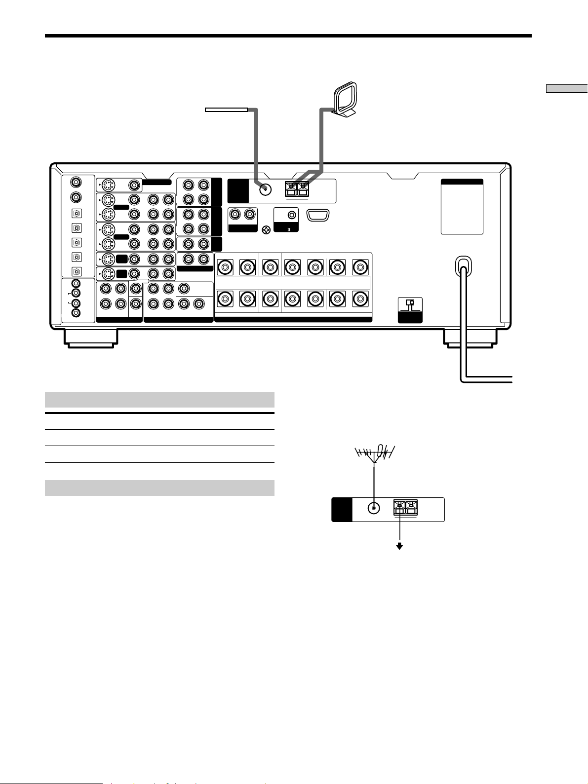
Terminals for connecting the antennas
Connect the To the
AM loop antenna AM terminals
FM wire antenna FM 75Ω COAXIAL terminal
L
SIGNAL GND
FM 75
COAXIAL
y
Ω
AM loop antenna
(supplied)
AC OUTLET
AM
y
CONTROL
A1
B
FRONTREAR CENTER A LRLRLR
+
–
IMPEDANCE USE 4 - 16Ω
SPEAKERS
4 Ω 8 Ω
IMPEDANCE
SELECTOR
z If you have poor FM reception
Use a 75-ohm coaxial cable (not supplied) to connect the receiver
to an outdoor FM antenna as shown below.
Outdoor FM antenna
Notes on antenna hookups
• To prevent noise pickup, keep the AM loop antenna
away from the receiver and other components.
• Be sure to fully extend the FM wire antenna.
• After connecting the FM wire antenna, keep it as
horizontal as possible.
Receiver
ANTENNA
FM 75
COAXIAL
Ω
AM
y
Ground wire
(not supplied)
To ground
Important
If you connect the receiver to an outdoor antenna, ground
it against lightning. To prevent a gas explosion, do not
connect the ground wire to a gas pipe.
Note
Do not use the SIGNAL GND y terminal for grounding the
receiver.
5
Page 6
Audio Component Hookups
Hooking Up the Components
Tape deck
INPUT OUTPUT
LINE
LINE
ç
ç
INOUT
S-VIDEO
VIDEO 1
VIDEO 2
DVD/
LD
TV/
SAT
REARFRONT
VIDEO
SUB
WOOFER
CENTER
CTRL S
CTRL S
STATUS
DVD/LD
IN COAX
CD
IN COAX
DVD/LD
IN OPT
TV/SAT
IN OPT
MD/DAT
IN OPT
MD/DAT
OUT OPT
CD
IN OPT
MONITOR
IN
L
VIDEO 1
OUT
DVD/
R
LD
TV/
SAT
IN
L
R
MONITOR OUT
R AUDIO
IN
OUT
IN
OUT
IN
IN
L
R
Turntable
(MM cartridge type only)
R
L
IN
L
PRE OUT5.1CH INPUT
REC
OUT
IN
REC
OUT
IN
2ND AUDIO OUT
SUB WOOFERREARFRONT
CENTER
TAPE
MD/
DAT
ANTENNA
R
PHONO
CD
SIGNAL GND
L
FM 75
COAXIAL
y
Ω
y
CONTROL
A1
IMPEDANCE USE 4 - 16Ω
SPEAKERS
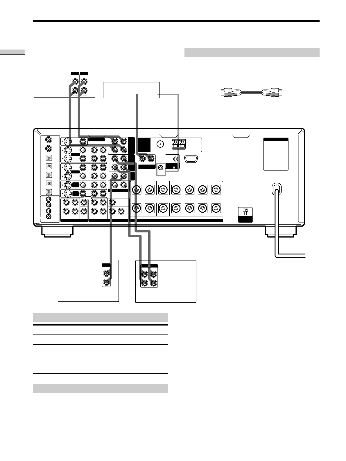
Required cords
Audio cords (not supplied)
When connecting a cord, be sure to match the color-coded pins to
the appropriate jacks on the components.
White (L) White (L)
Red (R) Red (R)
AC OUTLET
AM
FRONTREAR CENTER B A LRLRLR
+
–
4 Ω 8 Ω
IMPEDANCE
SELECTOR
ç
OUTPUT
LINE
L
R
CD player
Jacks for connecting audio components
Connect a To the
Turntable PHONO jacks
CD player CD jacks
Tape deck TAPE jacks
MD deck or DAT deck MD/DAT jacks
Note on audio component hookups
If your turntable has a ground wire, connect it to the
SIGNAL GND y terminal on the receiver.
INPUT OUTPUT
LINE
MD or DAT deck
INOUT
ç
LINE
L
R
6
Page 7
Video Component Hookups
DVD player
AUDIO OUT VIDEO
RL
DVD/LD
IN COAX
CD
IN COAX
DVD/LD
IN OPT
TV/SAT
IN OPT
MD/DAT
IN OPT
MD/DAT
OUT OPT
CD
IN OPT
CTRL S
MONITOR
IN
VIDEO 1
CTRL S
OUT
DVD/
LD
TV/
SAT
STATUS
IN
OUTPUT
L
R
S-VIDEO
OUT
VIDEO 1
VIDEO 2
DVD/
SAT
REARFRONT
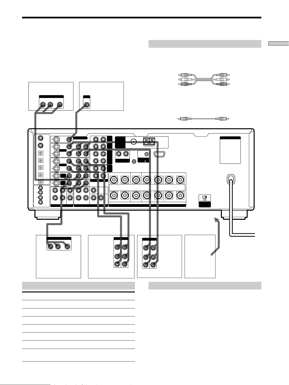
Required cords
Hooking Up the Components
Audio/video cords (not supplied)
When connecting a cord, be sure to match the color-coded pins to
the appropriate jacks on the components.
Yellow (video) Yellow (video)
White (L/audio) White (L/audio)
TV monitor
INPUT
VIDEO
IN
Red (R/audio) Red (R/audio)
Video cord for connecting a TV monitor (not supplied)
You can use the video cord of the supplied audio/video/control
S cord (see pages 11 and 12 for details).
Yellow Yellow
R
VIDEO
MONITOR OUT
R AUDIO
L
IN
OUT
IN
OUT
IN
LD
TV/
IN
CENTER
L
R
SUB
WOOFER
PRE OUT5.1CH INPUT
IN
REC
OUT
IN
REC
OUT
IN
2ND AUDIO OUT
SUB WOOFERREARFRONT
CENTER
L
ANTENNA
TAPE
MD/
DAT
CD
R
PHONO
L
SIGNAL GND
FM 75
COAXIAL
y
Ω
CONTROL
y
A1
AM
FRONTREAR CENTER B A
LRLRLR
AC OUTLET
+
–
IMPEDANCE USE 4 - 16Ω
SPEAKERS
4 Ω 8 Ω
IMPEDANCE
SELECTOR
ç
OUTPUT
AUDIO OUT VIDEO
RL
OUT
Satellite tuner*
or TV tuner
Jacks for connecting video components
Connect a To the
Satellite tuner* or TV tuner TV/SAT* or TV/LD jacks
VCR VIDEO 1 jacks
Additional VCR VIDEO 2 jacks
DVD player DVD/LD* or DVD jacks
LD player DVD/LD* or TV/LD jacks
TV monitor MONITOR VIDEO OUT jack
Camcorder or video game VIDEO 3 INPUT jacks on the
U.S.A./Canada models only.
*
front panel
VCR
INPUT OUTPUT
VIDEO
VIDEO
OUT
IN
AUDIO
AUDIO
OUT
IN
INOUT
ç
L
R
To the front panel
INOUT
ç
ç
INPUT OUTPUT
VIDEO
VIDEO
OUT
IN
AUDIO
AUDIO
OUT
IN
L
R
VCR
Note on video component hookups
You can connect your TV’s audio output jacks to the TV/
SAT* (or TV/LD) AUDIO IN jacks on the receiver and
apply sound effects to the audio from the TV. In this case,
do not connect the TV’s video output jack to the TV/SAT*
(or TV/LD) VIDEO IN jacks on the receiver. If you are
connecting a separate TV tuner (or satellite tuner), connect
both the audio and video output jacks to the receiver as
shown above.
U.S.A./Canada models only.
*
z
When using the S-video jacks instead of the video jacks
Your monitor must also be connected via an S-video jack. S-video
signals are on a separate bus from the video signals and will not
be output through the video jacks.
Camcorder
or video
game
U.S.A./Canada models
*
only.
7
Page 8
Digital Component Hookups
Hooking Up the Components
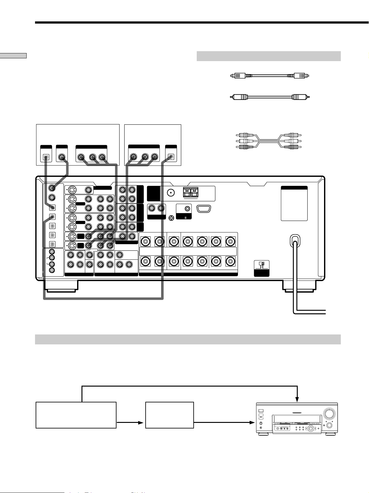
Connect the digital output jacks of your DVD player and
satellite tuner (etc.) to the receiver’s digital input jacks to
bring the multi channel surround sound of a movie
theater into your home. To enjoy the full effect of multi
channel surround sound, five speakers (two front
speakers, two rear speakers, and a center speaker) and a
sub woofer are required. You can also connect an LD
player with an RF OUT jack via an RF demodulator, like
the Sony MOD-RF1 (not supplied).
DVD player (etc.)*
OUTPUT
OUTPUT
DIGITAL
OPTICAL
CTRL S
IN
CTRL S
OUT
STATUS
IN
COAXIAL
DVD/LD
IN COAX
CD
IN COAX
DVD/LD
IN OPT
TV/SAT
IN OPT
MD/DAT
IN OPT
MD/DAT
OUT OPT
CD
IN OPT
MONITOR
VIDEO 1
DVD/
LD
TV/
SAT
DIGITAL
L
R
S-VIDEO
OUT
VIDEO 1
VIDEO 2
DVD/
LD
TV/
SAT
REARFRONT
OUTPUT
AUDIO OUTVIDEO
RL
VIDEO
CENTER
SUB
WOOFER
MONITOR OUT
R AUDIO
IN
OUT
IN
OUT
IN
IN
L
R
L
PRE OUT5.1CH INPUT
Satellite tuner** or
OUTPUT
OUT
R
L
IN
REC
OUT
IN
REC
OUT
IN
2ND AUDIO OUT
TAPE
MD/
DAT
CD
CENTER
SUB WOOFERREARFRONT
TV tuner
AUDIO OUTVIDEO
RL
ANTENNA
R
PHONO
L
SIGNAL GND
OUTPUT
DIGITAL
OPTICAL
FM 75
COAXIAL
y
Ω
y
CONTROL
A1
IMPEDANCE USE 4 - 16Ω
SPEAKERS
Required cords
Optical digital cords (not supplied)
Black Black
Coaxial digital cord (not supplied)
Yellow Yellow
Audio/video cords (not supplied)
When connecting a cord, be sure to match the color-coded pins to
the appropriate jacks on the components.
Yellow (video) Yellow (video)
White (L/audio) White (L/audio)
Red (R/audio) Red (R/audio)
AC OUTLET
AM
FRONTREAR CENTER B A
LRLRLR
+
–
4 Ω 8 Ω
IMPEDANCE
SELECTOR
Make either coaxial or optical connections. We recommended making coaxial connections instead of optical connections.
*
U.S.A./Canada models only.
**
Example of LD player connected via an RF demodulator
Please note that you cannot connect an LD player’s DOLBY DIGITAL RF OUT jack directly to this unit’s digital input jacks.
You must first convert the RF signal to either an optical or coaxial digital signal. Connect the LD player to the RF
demodulator, then connect the RF demodulator’s optical or coaxial digital output to this unit’s OPT or COAX DVD/LD*
(or TV/LD) IN jack. Refer to the instruction manual supplied with your RF Demodulator for details on DOLBY DIGITAL
RF hookups.
DVD/LD*
L AUDIO R
SOUND FIELD PRESET
(or TV/LD)
VIDEO IN
MULTI CHANNEL DECODING
SOUND FIELD
–+ MODE
EQ SUR LEVEL
NAME CUSTOM SET UP
2 CH ANALOG DIRECT EQ BANK 5.1 CH INPUT
+
–
ENTER
MASTER VOLUME
5
4
3
2
1
0
AUDIO SPLIT DIGITAL / ANALOG
INPUT
SELECTOR
OPEN/
CLOSE
6
10
VIDEO OUT
DOLBY
DIGITAL
RF OUT
DIGITAL
DVD/LD*
RF demodulatorLD player
(or TV/LD) IN
(COAX or OPT)
OFF
A+B
1/u
SPEAKERS
A
B
PHONES
FM/AM TUNER PRESET
–+–+
MEMORY A.F.D
VIDEOS-VIDEO
Note
When making connections as shown above, be sure to set DIGITAL/ANALOG (4 on page 25) manually. This unit may not operate
correctly if DIGITAL/ANALOG is set to “AUTO.”
U.S.A./Canada models only.
*
8
7
8
9
Page 9
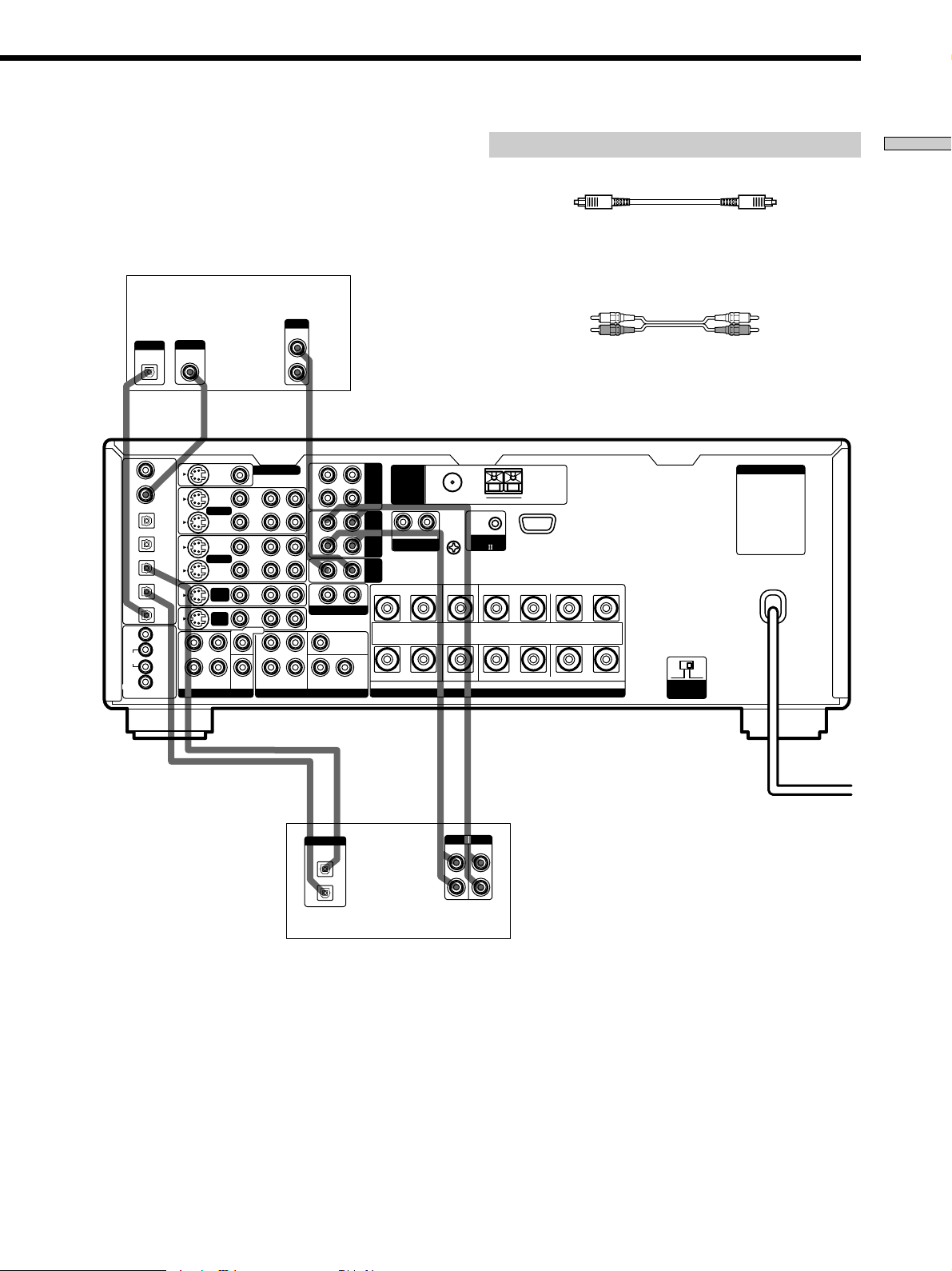
Connect the digital output jack of your MD or DAT deck
to the receiver’s digital input jack and connect the digital
input jack of your MD or DAT deck to the receiver’s
digital output jack. These connections allow you to make
digital recordings of CDs and TV broadcasts.
CD player
OUTPUT
MONITOR OUT
IN
OUT
IN
OUT
IN
IN
CENTER
L
R
R AUDIO
LINE
L
PRE OUT5.1CH INPUT
L
R
R
IN
REC
OUT
IN
REC
OUT
IN
2ND AUDIO OUT
SUB WOOFERREARFRONT
CENTER
L
ANTENNA
TAPE
MD/
R
DAT
PHONO
CD
CTRL S
CTRL S
STATUS
OUTPUT
IN
OUT
IN
DIGITAL
OPTICAL
DVD/LD
IN COAX
CD
IN COAX
DVD/LD
IN OPT
TV/SAT
IN OPT
MD/DAT
IN OPT
MD/DAT
OUT OPT
CD
IN OPT
MONITOR
VIDEO 1
DVD/
LD
TV/
SAT
OUTPUT
DIGITAL
COAXIAL
S-VIDEO
L
R
VIDEO 1
VIDEO 2
DVD/
LD
TV/
SAT
REARFRONT
VIDEO
SUB
WOOFER
L
SIGNAL GND
FM 75
COAXIAL
Ω
y
Required cords
Optical digital cords (not supplied)
Black Black
Audio cords (not supplied)
When connecting a cord, be sure to match the color-coded pins to
the appropriate jacks on the components.
White (L) White (L)
Red (R) Red (R)
AC OUTLET
AM
y
CONTROL
A1
FRONTREAR CENTER B A LRLRLR
+
–
IMPEDANCE USE 4 - 16Ω
SPEAKERS
4 Ω 8 Ω
IMPEDANCE
SELECTOR
Hooking Up the Components
ç
DIGITAL
OPTICAL
OUT
IN
INOUT
ç
ç
INPUT OUTPUT
LINE
INOUT
ç
LINE
L
R
MD or DAT deck
Make either coaxial or optical connections. We recommended making coaxial connections instead of optical connections.
*
Notes
• Please note that you cannot make a digital recording of a digital multi channel surround signal.
• All OPT and COAX jacks are compatible with 32 kHz, 44.1 kHz, 48 kHz and 96 kHz sampling frequencies and 24 bit word length.
• It is not possible to record analog signals to MD/DAT, TAPE and VIDEO with only digital connections. Be sure to make both digital and
analog connections to your digital components.
9
Page 10
AC OUTLET
REAR
CENTER
WOOFER
5.1 CH OUTPUT
FRONT
+
–
SPEAKERS
IMPEDANCE USE 4 - 16Ω
FRONTREAR CENTER B A
LRLRLR
R
L
R
L
R
IN
REC
OUT
IN
IN
OUT
IN
IN
IN
OUT
IN
CENTER
SUB WOOFERREARFRONT
CENTER
SUB
WOOFER
REARFRONT
TV/
SAT
DVD/
LD
VIDEO 1
MONITOR OUT
VIDEO 2
REC
OUT
L
R AUDIO
S-VIDEO
DVD/LD
IN COAX
CD
IN COAX
DVD/LD
IN OPT
TV/SAT
IN OPT
MD/DAT
IN OPT
MD/DAT
OUT OPT
CD
IN OPT
MONITOR
CTRL S
IN
STATUS
IN
CTRL S
OUT
VIDEO 1
DVD/
LD
TV/
SAT
VIDEO
L
2ND AUDIO OUT
PRE OUT5.1CH INPUT
4 Ω 8 Ω
IMPEDANCE
SELECTOR
CONTROL
A1
TAPE
MD/
DAT
CD
L
SIGNAL GND
AM
y
y
FM 75
Ω
COAXIAL
ANTENNA
PHONO
R
5.1CH Input Hookups
Hooking Up the Components
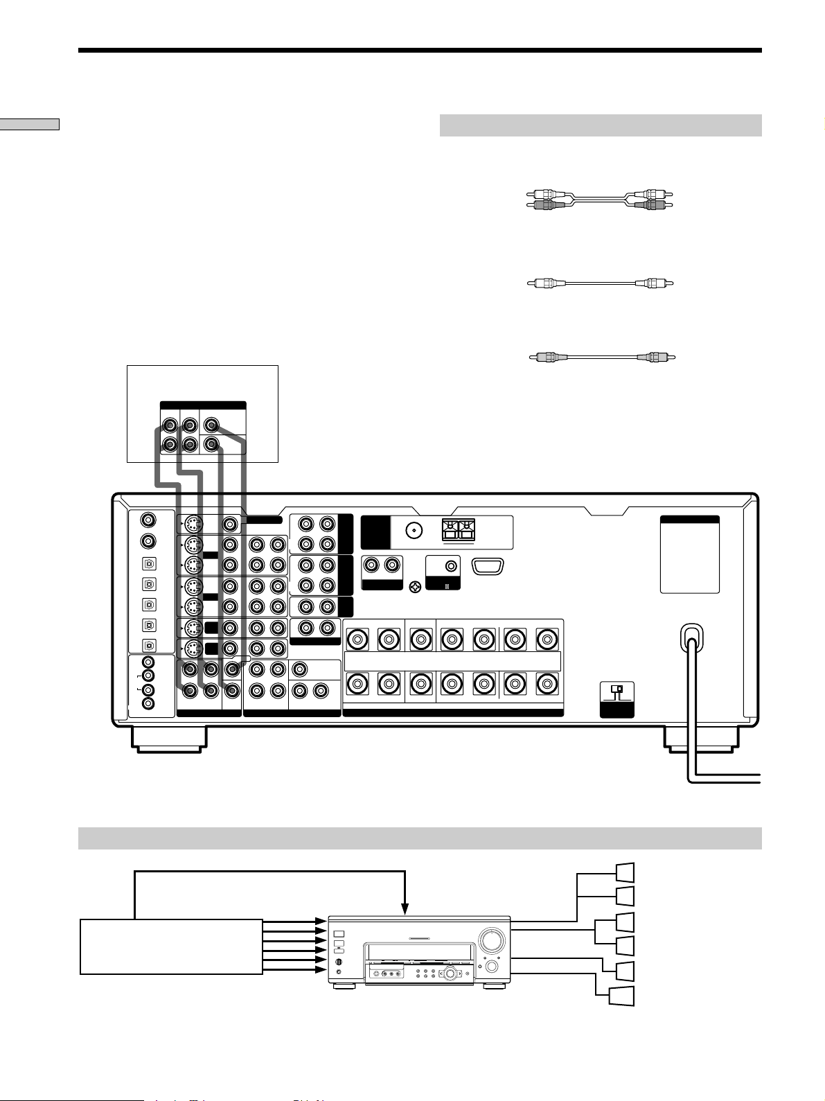
Although this receiver incorporates a multi channel
decoder, it is also equipped with 5.1CH INPUT jacks.
These connections allow you to enjoy multichannel
software encoded in formats other than Dolby Digital
(AC-3) and DTS. If your DVD player is equipped with
5.1CH OUTPUT jacks, you can connect them directly to
this unit to enjoy the sound of the DVD player’s multi
channel decoder. Alternatively, the 5.1CH INPUT jacks
can be used to connect an external multi channel decoder.
To fully enjoy multi channel surround sound, you will
need five speakers (two front speakers, two rear speakers,
and a center speaker) and a sub woofer. Refer to the
instruction manual supplied with your DVD player, multi
channel decoder, etc., for details on the 5.1 channel input
hookups.
DVD player,
Multichannel decoder, etc.**
Required cords
Audio cords (not supplied)
Two for the 5.1CH INPUT FRONT and REAR jacks
White (L) White (L)
Red (R) Red (R)
Monaural audio cords (not supplied)
Two for the 5.1CH INPUT CENTER and SUB WOOFER jacks
Black Black
Video cord (not supplied)
One for the DVD/LD* (or DVD) VIDEO IN jacks (etc.)
Yellow Yellow
Note
When using the connections described below, adjust the level of
your surround speakers and sub woofer from the DVD player or
multichannel decoder.
U.S.A./Canada models only.
*
** If these components have analog output jacks to output downmixed 2-channel audio, you can record the audio on a tape or MD.
To do this, connect the output jacks for the downmixed audio to the input jacks you want to assign for the component. You cannot assign the
component to the PHONO and TUNER functions.
Example of a DVD player hookup using the 5.1 INPUT jacks
Note
See page 15 for details on speaker system hookup.
*
VIDEO OUT
DVD player
U.S.A./Canada models only.
5.1CH INPUT
1/ u
SPEAKERS
A
B
OFF
A+B
PHONES
FM/AM TUNER PRESET
MEMORY – + – + A.F.D
L AUDIO R
VIDEOS-VIDEO
DVD/LD* (or DVD)
IN VIDEO etc.
MULTI CHANNEL DECODING
–+ MODE
EQ SUR LEVEL
TUNER CUSTOM SET UP
2 CH ANALOG DIRECT EQ BANK 5.1 CH INPUT
+
–
ENTER
SOUND FIELD PRESET SOUND FIELD
MASTER VOLUME
5
4
3
2
1
0
AUDIO SPLIT DIGITAL / ANALOG
INPUT
SELECTOR
OPEN/
CLOSE
6
10
SPEAKERS
FRONT
7
8
SPEAKERS
9
REAR/CENTER
SUB WOOFER
Front Speaker (L)
Front Speaker (R)
Rear Speaker (L)
Rear Speaker (R)
Center Speaker
Active Woofer
10
Page 11
Other Hookups
CTRL S
STATUS
CTRL S
Required cords
Hooking Up the Components
Audio cords (not supplied)
When connecting a cord, be sure to match the color-coded pins to the
appropriate jacks on the components.
White (L) White (L)
Red (R) Red (R)
Audio/video/control S connecting cord (1***)
Yellow (video) A
White (L/audio) B
Red (R/audio) C
Black (control S) D
Yellow (video) A
White (L/audio) B
Red (R/audio) C
Black (control S) D
CONTROL S connecting cord (1***)
Black E Black E
CONTROL A1
R
S-VIDEO
VIDEO 1
VIDEO 2
DVD/
LD
TV/
SAT
REARFRONT
VIDEO
SUB
WOOFER
MONITOR OUT
IN
OUT
IN
OUT
IN
IN
CENTER
L
R
R AUDIO
L
PRE OUT5.1CH INPUT
DVD/LD
IN COAX
CD
IN COAX
DVD/LD
IN OPT
TV/SAT
IN OPT
MD/DAT
IN OPT
MD/DAT
OUT OPT
CD
IN OPT
MONITOR
IN
L
VIDEO 1
OUT
DVD/
R
LD
TV/
SAT
IN
IN
REC
OUT
IN
REC
OUT
IN
2ND AUDIO OUT
SUB WOOFERREARFRONT
CENTER
L
ANTENNA
TAPE
MD/
DAT
CD
R
PHONO
L
SIGNAL GND
FM 75
COAXIAL
y
Ω
y
CONTROL
A1
IMPEDANCE USE 4 - 16Ω
SPEAKERS
**
AM
FRONTREARCENTER B A LRLRLR
+
–
4 Ω 8 Ω
IMPEDANCE
SELECTOR
AC OUTLET
AC OUTLET
*
CTRL S (STATUS) IN/OUT
2ND AUDIO OUT
AC power cord
To a wall outlet
The configuration, shape, and number of AC outlets on the rear panel varies according to the model and country to which the receiver is shipped.
*
This jack is intended only for use in the manufacturing and servicing of the unit.
**
U.S.A./Canada models only
***
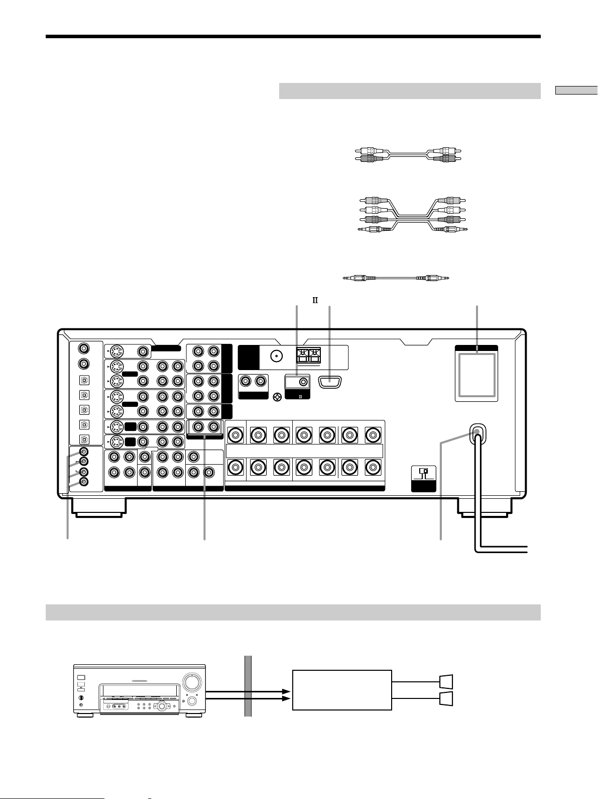
Example of a sub room hookup using the 2ND AUDIO OUT jacks
You can use the 2ND AUDIO OUT jacks to output audio signals to a stereo amplifier located in another room.
Select the source in the CUSTOMIZE menu (page 46) to switch the audio signals output to the sub room.
Main room
MASTER VOLUME
2ND
5
6
4
7
3
AUDIO
8
2
OUT
9
1
10
0
AUDIO SPLIT DIGITAL / ANALOG
INPUT
SELECTOR
OPEN/
CLOSE
+
–
ENTER
SPEAKERS
OFF
A+B
1/ u
A
B
PHONES
FM/AM TUNER PRESET
SOUND FIELD PRESET SOUND FIELD
MEMORY – + – + A.F.D
L AUDIO R
VIDEOS-VIDEO
MULTI CHANNEL DECODING
–+ MODE
EQ SUR LEVEL
TUNER CUSTOM SET UP
2 CH ANALOG DIRECT EQ BANK 5.1 CH INPUT
Note
This function is not available when 5.1CH INPUT is selected.
AUDIO
IN
Sub room
Stereo amplifier
SPEAKERS
R
Speaker (L)
L
Speaker (R)
11
Page 12
Other Hookups
Hooking Up the Components
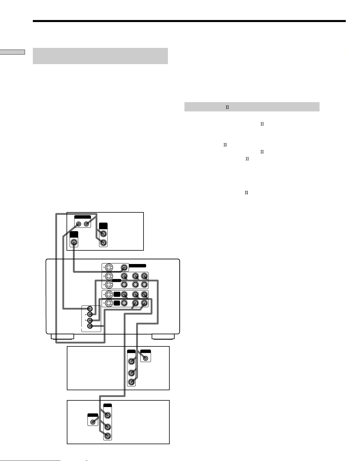
S-LINK CONTROL S hookup (U.S.A./Canada
models only)
If you have a S-LINK CONTROL S-compatible Sony TV,
satellite tuner, monitor, DVD player or VCR, use an
audio/video/control S connecting cord or a control S
connecting cord to connect the CTRL S (STATUS) IN (for
TV, satellite tuner, or monitor) or OUT (for VCR, etc.) jack
on the receiver to the appropriate S-LINK jack on the
respective component. Refer to the operating instructions
supplied with your TV, satellite tuner, monitor, VCR, etc.,
for details.
The following illustration is an example of S-LINK
CONTROL S hookups between the receiver, a TV, a VCR,
and a DVD player. When your TV is connected to the
receiver as shown below, the TV input mode will change
to video input whenever you turn on the receiver. When
you connect the receiver as shown below, the input mode
of the receiver changes to VIDEO 1 or DVD/LD whenever
you play your VCR or DVD.
The following connections also change the input mode of
the receiver to TV whenever you operate your TV.
VIDEO
IN
S-LINK
OUT IN
A
CTRL S
CTRL S
STATUS
IN
OUT
IN
TV
Receiver
****
DE
MONITOR
VIDEO 1
DVD/
LD
TV/
SAT
AUDIO
OUT
S-VIDEO
B
C
VIDEO 1
DVD/
LD
TV/
SAT
VIDEO
MONITOR OUT
R AUDIO
IN
OUT
IN
IN
* Audio/video/control S connecting cord (Pull the video cord away
from the supplied audio/video/control S cable for connection A.)
** Control S connecting cord
Note
Refer to the instructions supplied with your TV for details
regarding the operations you can control from your TV.
CONTROL A1 hookup
• If you have a CONTROL A1 compatible Sony
CD player, tape deck, or MD deck
Use a CONTROL A1 cord (not supplied) to connect the
CONTROL A1
MD deck to the CONTROL A1
Refer to “CONTROL A1
and the operating instructions supplied with your CD
player, tape deck, or MD deck for details.
Note
If you make CONTROL A1 connections from the receiver to
an MD deck that is also connected to a computer, do not
operate the receiver while using the “Sony MD Editor”
software. This may cause a malfunction.
• If you have a Sony CD changer with a
COMMAND MODE selector
If your CD changer’s COMMAND MODE selector can
be set to CD 1, CD 2, or CD 3, be sure to set the
command mode to “CD 1” and connect the changer to
the CD jacks on the receiver.
L
If, however, you have a Sony CD changer with VIDEO
OUT jacks, set the command mode to “CD 2” and
connect the changer to the VIDEO 2 jacks on the
receiver.
jack on the CD player, tape deck, or
jack on the receiver.
Control System” on page 55
VCR 1
DVD player
12
S-LINK
IN
*
S-LINK
OUTPUT
IN
VIDEO
OUT
AUDIO
OUT
*
OUTPUT
VIDEO
OUT
AUDIO
OUT
Page 13
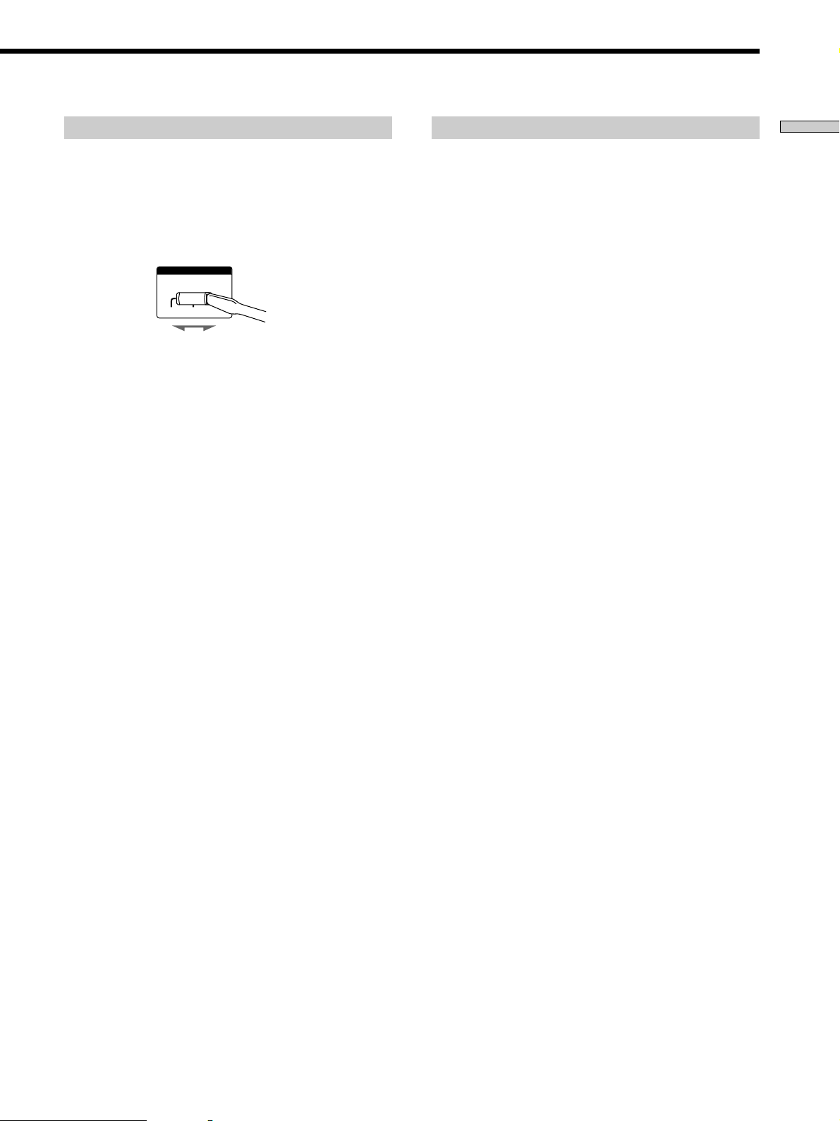
Setting a voltage selector
Connecting the AC power cord
Hooking Up the Components
If your receiver has a voltage selector on the rear panel,
check that the voltage selector on the rear panel of the
receiver is set to the local power supply voltage. If not,
use a screwdriver to set the selector to the correct position
before connecting the AC power cord to a wall outlet.
VOLTAGE SELECTOR
220V120V
240V
Before connecting the AC power cord of this receiver to a
wall outlet:
• Connect the speaker system to the receiver (see page
15).
• Turn the MASTER VOLUME control to the leftmost
position (0).
Connect the AC power cord(s) of your audio/video
components to a wall outlet.
If you connect other audio/video components to the AC
OUTLET(s) on the receiver, the receiver will supply power
to the connected component(s), allowing you to turn the
whole system on or off when you turn the receiver on/off.
Caution
Make sure that the total power consumption of the component(s)
connected to the receiver’s AC OUTLET(s) does not exceed the
wattage stated on the rear panel. Do not connect high-wattage
electrical home appliances such as electric irons, fans, or TVs to
this outlet.
Note
If the AC power cord is disconnected for about two weeks, the
receiver’s entire memory will be cleaned and the demonstration
will start.
13
Page 14
Hooking Up and Setting Up the Speaker System
This chapter describes how to hook
up your speaker system to the
receiver, how to position each speaker,
and how to set up your speakers to
enjoy multi channel surround sound.
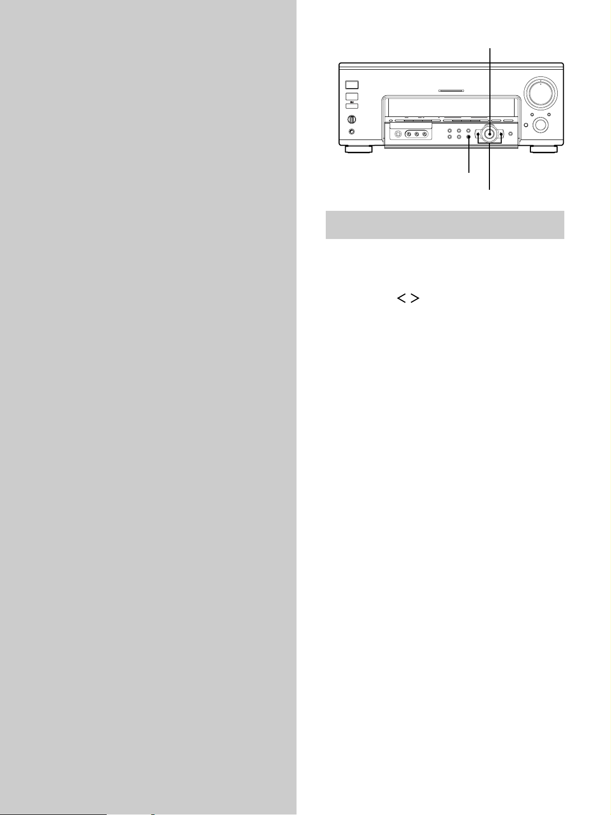
Jog dial
MASTER VOLUME
5
4
+
2
AUDIO SPLIT DIGITAL / ANALOG
OPEN/
CLOSE
ENTER
3
1
0
INPUT
SELECTOR
1/ u
SPEAKERS
A
B
OFF
A+B
PHONES
FM/AM TUNER PRESET SOUND FIELD PRESET SOUND FIELD
MEMORY – + – + A.F.D 2 CH ANALOG DIRECT EQ BANK 5.1CH INPUT
VIDEOS-VIDEO
L AUDIO R
MULTI CHANNEL DECODING
EQ SUR LEVEL
TUNER CUSTOM SET UP
– +
MODE
–
SET UP
Cursor buttons
Brief descriptions of buttons and controls
used to set up the speaker system
SET UP button: Press to enter the setup mode when
specifying speaker types and distances.
Cursor buttons ( / ): Use to select parameters after
pressing the SET UP button.
Jog dial: Use to adjust the setting of each parameter.
6
7
8
9
10
14
Page 15
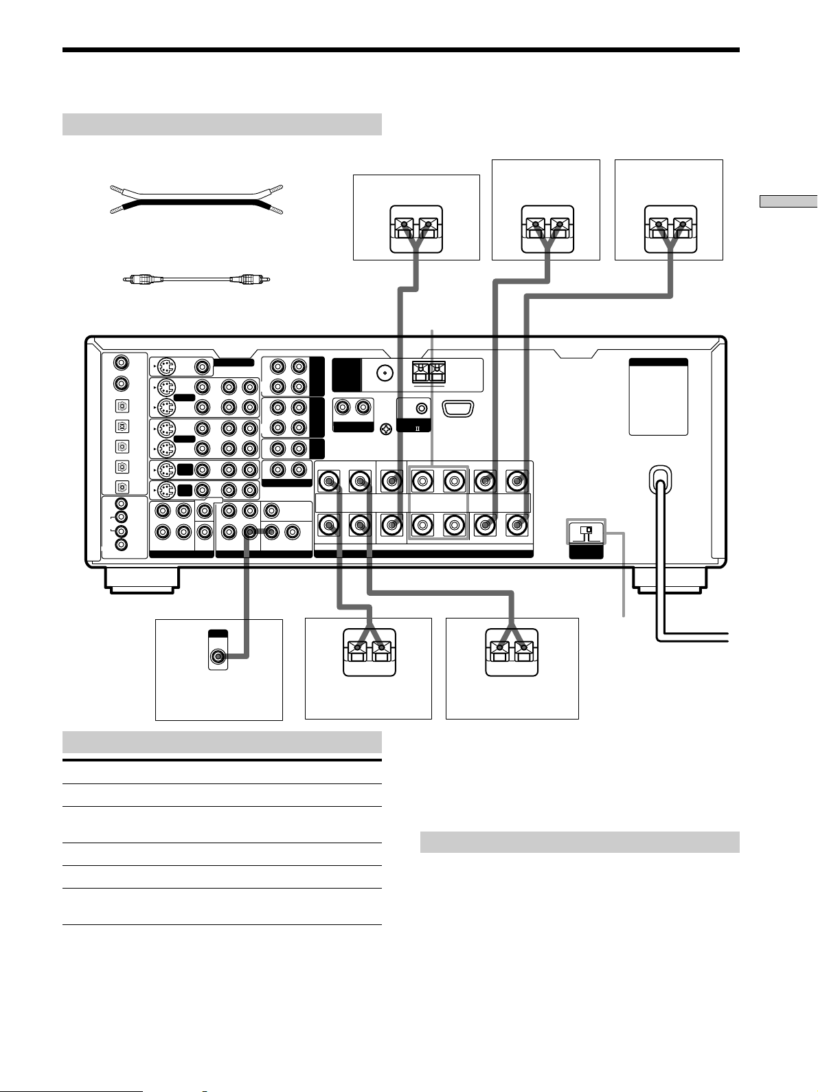
Speaker System Hookup
Required cords
Speaker cords (not supplied)
One for each front, rear, and center speaker
(+) (+)
(–) (–)
Monaural audio cord (not supplied)
One for an active sub woofer
Black Black
R
IN
REC
OUT
IN
REC
OUT
IN
2ND AUDIO OUT
SUB WOOFERREARFRONT
CENTER
L
TAPE
MD/
DAT
CD
CTRL S
CTRL S
STATUS
S-VIDEO
VIDEO 1
VIDEO 2
DVD/
LD
TV/
SAT
REARFRONT
VIDEO
SUB
WOOFER
MONITOR OUT
IN
OUT
IN
OUT
IN
IN
CENTER
L
R
R AUDIO
L
PRE OUT5.1CH INPUT
DVD/LD
IN COAX
CD
IN COAX
DVD/LD
IN OPT
TV/SAT
IN OPT
MD/DAT
IN OPT
MD/DAT
OUT OPT
CD
IN OPT
MONITOR
IN
L
VIDEO 1
OUT
DVD/
R
LD
TV/
SAT
IN
ANTENNA
R
PHONO
Center speaker
}
FM 75
Ω
y
COAXIAL
L
CONTROL
SIGNAL GND
y
IMPEDANCE USE 4 - 16Ω
FRONT
SPEAKERS B
AM
A1
SPEAKERS
]
FRONTREAR CENTER B A
Front speaker (R) Front speaker (L)
]
}
LRLRLR
}
AC OUTLET
+
–
4 Ω 8 Ω
IMPEDANCE
SELECTOR
Hooking Up and Setting Up the Speaker System
]
INPUT
AUDIO
IN
Active sub woofer
}
Rear speaker (R) Rear speaker (L)
Terminals for connecting the speakers
Connect the To the
Front speakers (8 or 4* ohm) SPEAKERS FRONT A terminals
Additional pair of front SPEAKERS FRONT B terminals
speakers (8 or 4* ohm)
Rear speakers (8 or 4* ohm) SPEAKERS REAR terminals
Center speaker (8 or 4* ohm) SPEAKERS CENTER terminals
Active sub woofer SUB WOOFER AUDIO OUT
* See “Speaker impedance” on the next page.
** You can connect an active sub woofer to either of the two jacks. The
remaining jack can be used to connect a second active sub woofer.
jack**
IMPEDANCE
SELECTOR
]
z
}
To connect certain speakers to another amplifier
]
Use the PRE OUT jacks. The same signal is output from both the
SPEAKERS jacks and the PRE OUT jacks. For example, if you
want to connect just the front speakers to another amplifier,
connect that amplifier to the PRE OUT FRONT L and R jacks.
Notes on speaker system hookup
• Twist the stripped ends of the speaker cords about 2/3
inch (10 mm). Be sure to match the speaker cord to the
appropriate terminal on the components: + to + and –
to –. If the cords are reversed, the sound will be
distorted and will lack bass.
• If you use front speakers with low maximum input
rating, adjust the volume carefully to avoid excessive
output on the speakers.
15
Page 16
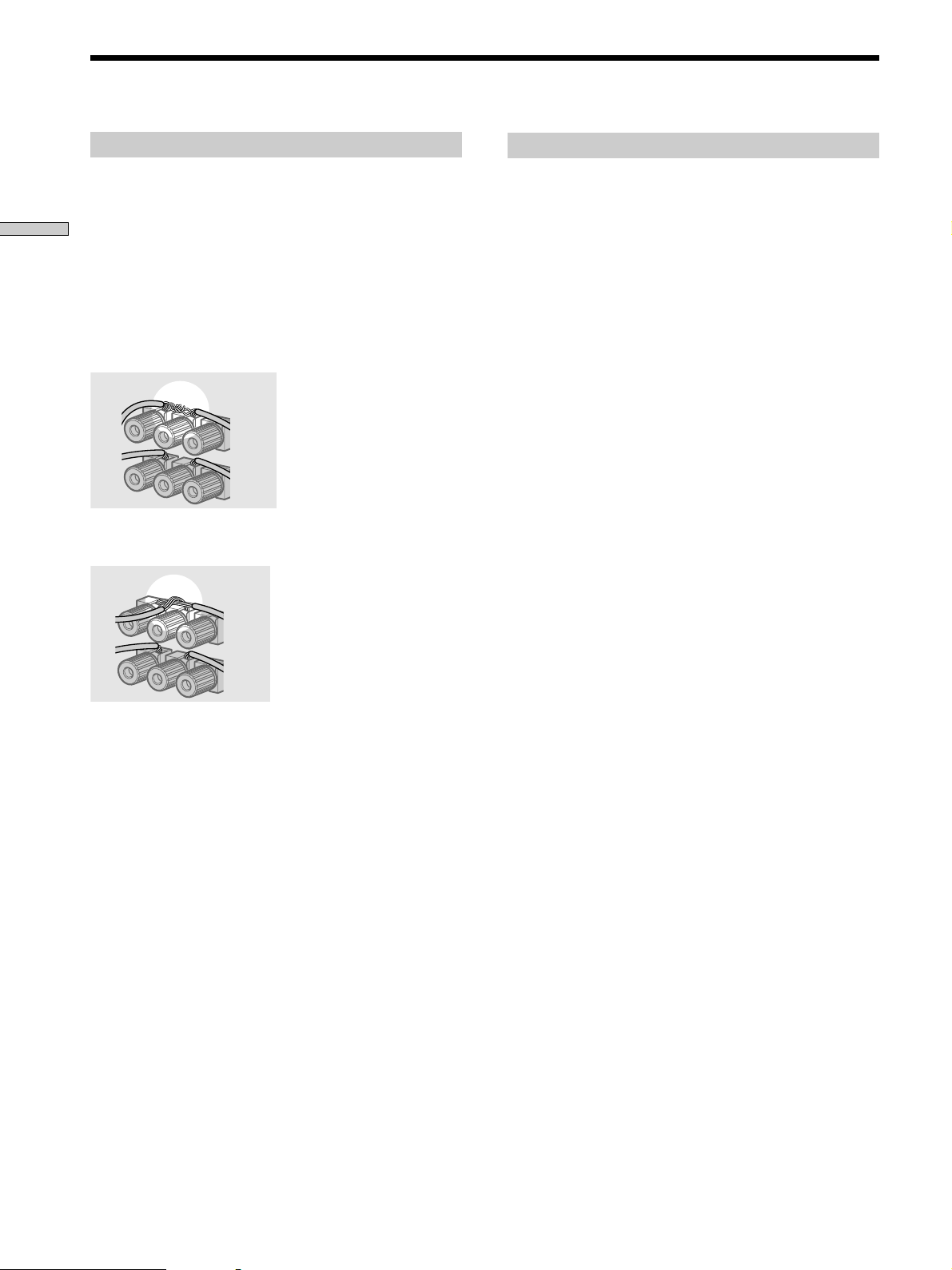
Speaker System Hookup
To avoid short-circuiting the speakers
Short-circuiting of the speakers may damage the receiver.
To prevent this, make sure to take the following
Hooking Up and Setting Up the Speaker System
precautions when connecting the speakers.
Make sure the stripped ends of each speaker cord
does not touch another speaker terminal or the
stripped end of another speaker cord.
Examples of poor conditions of the speaker cord
Stripped speaker cord is touching another speaker terminal.
Speaker impedance
To enjoy multi channel surround, connect front, center,
and rear speakers with a nominal impedance of 8 ohms or
higher, and set the speaker IMPEDANCE SELECTOR to
“8Ω.” Check the instruction manual supplied with your
speakers if you’re not sure of their impedance. (This
information is usually printed on a label on the back of
the speaker.)
If you connect any speaker to the FRONT, CENTER or
REAR SPEAKERS terminals with a nominal impedance
between 4 ohms and 8 ohms, you must set the
IMPEDANCE SELECTOR to “4Ω.”
Notes
• Be sure to connect front speakers with a nominal impedance of
8 ohms or higher if you want to select both sets (A+B) of front
speakers (see page 27).
• Speakers with an impedance of less than 4 ohms cannot be
used.
Stripped cords are touching each other due to excessive
removal of insulation.
After connecting all the components, speakers,
and AC power cord, output a test tone to check
that all the speakers are connected correctly. For
details on outputting a test tone, see page 21.
If no sound is heard from a speaker while outputting a
test tone or a test tone is output from a speaker other than
the one whose name is currently displayed on the
receiver, the speaker may be short-circuited. If this
happens, check the speaker connection again.
16
Page 17
Performing Initial Setup Operations
Once you have hooked up the speakers and turned on the
power, clear the receiver’s memory. Then specify the
speaker parameters (size, position, etc.) and perform any
other initial setup operations necessary for your system.
Before turning on the receiver
Make sure that you have:
• Turned MASTER VOLUME to the leftmost position (0).
• Selected the appropriate front speakers (see “@∞
SPEAKERS selector” on page 27).
Clearing the receiver’s memory
Before using your receiver for the first time, or when you
want to clear the receiver’s memory, do the following.
– +
MODE
Jog dial
2 CH ANALOG DIRECT EQ BANK 5.1CH INPUT
+
–
2
AUDIO SPLIT DIGITAL / ANALOG
ENTER
MASTER VOLUME
5
6
4
7
3
1
OPEN/
CLOSE
8
9
10
0
INPUT
SELECTOR
1/u
1/ u
SPEAKERS
OFF
A+B
PHONES
MULTI CHANNEL DECODING
A
B
MEMORY – + – + A.F.D
FM/AM TUNER PRESET
VIDEOS-VIDEO
SOUND FIELD PRESET SOUND FIELD
L AUDIO R
EQ SUR LEVEL
TUNER CUSTOM SET UP
Performing initial setup operations
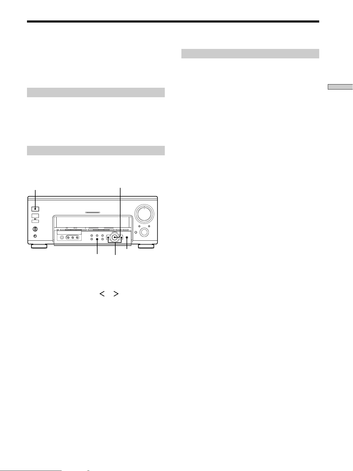
Before using your receiver for the first time, use the SET
UP button to adjust the setup parameters so that they
correspond to your system. You can adjust the following
items. For details on how to make adjustments, see the
page in parenthesis.
• Speaker size and placement (pages 18~19).
• Speaker distance (page 20).
Hooking Up and Setting Up the Speaker System
CUSTOM
Cursor buttons
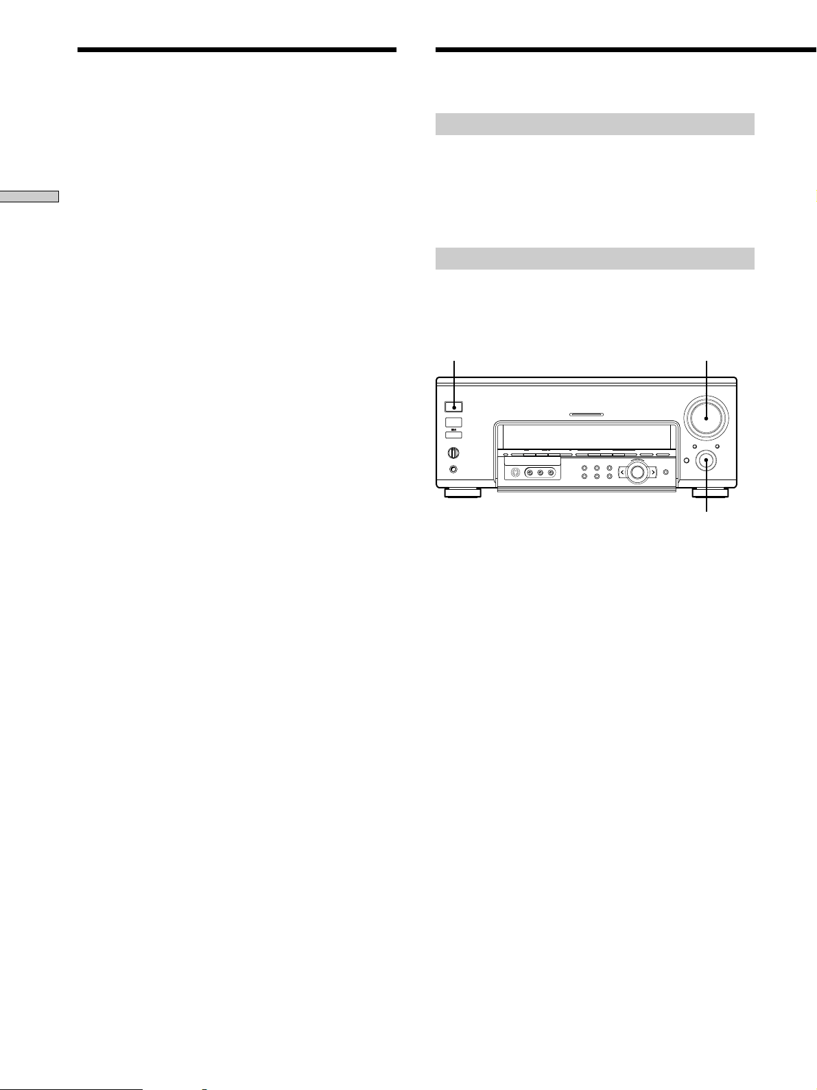
1 Press CUSTOM.
ENTER
CUSTOMIZE menu appears in the display.
2 Press the cursor buttons ( or ) repeatedly to
display “MEMORY CLEAR [NO]”.
3 Turn the jog dial to display “MEMORY CLEAR
[YES]” and press ENTER.
“Are you sure? [NO]” is displayed.
4 Turn the jog dial to display “Are you sure? [YES]”
and press ENTER.
The unit automatically turns off, and then turns on
again. All of the followings are reset to the factory
settings or cleared.
• All menu adjustments (speaker settings, equalizer
settings, sound field parameters, etc.).
• The equalizer settings in the equalizer bank.
17
Page 18
Multi Channel Surround Setup
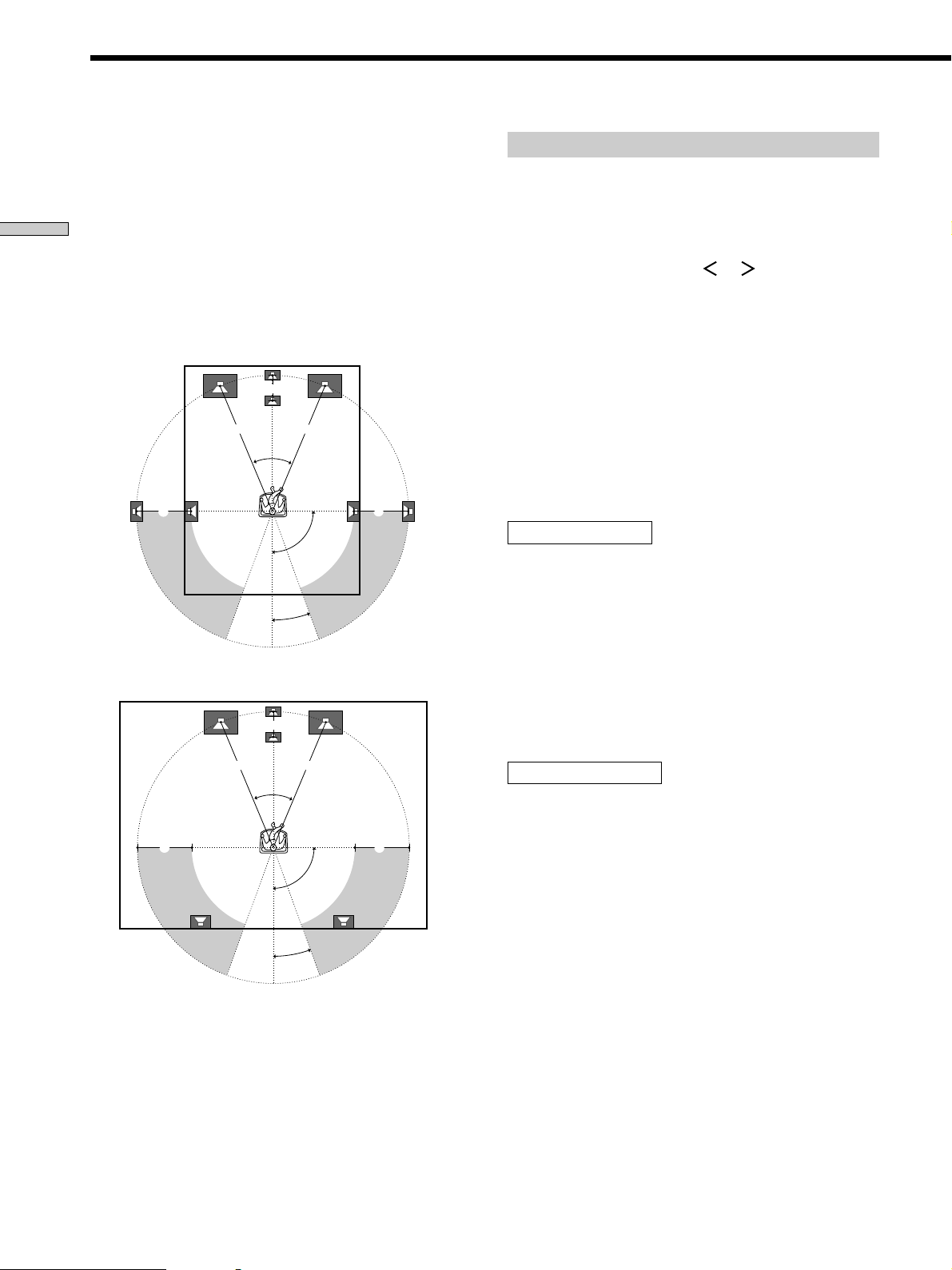
For the best possible surround sound all speakers should
be the same distance from the listening position (A).
However, this unit lets you to place the center speaker up
to 5 feet (1.5 meters) closer (B) and the rear speakers up
to 15 feet (4.5 meters) closer (C) to the listening position.
Hooking Up and Setting Up the Speaker System
The front speakers can be placed from 3 to 40 feet (1.0 to
12.0 meters) from the listening position (A).
You can place the rear speakers either behind you or to
the side, depending on the shape of your room (etc.).
When placing rear speakers to your side
B
A A
45°
CC
90°
20°
When placing rear speakers behind you
B
A A
45°
CC
90°
20°
Note
Do not place the center speaker farther away from the listening
position than the front speakers.
Specifying the speaker parameters
1 Press 1/u to turn on the receiver.
2 Press SET UP.
3 Press the cursor buttons ( or ) repeatedly to
select the parameter you want to adjust.
4 Turn the jog dial to select setting you desire. The
setting is entered automatically.
5 Repeat steps 3 and 4 until you have set all of the
parameters that follow.
Note
When the adjustable range is exceeded, the display blinks. Please
keep settings within areas A, B and C as described on the left.
p Front speaker size
FRONT SP [LARGE]
Initial setting : LARGE
• If you connect large speakers that will effectively
reproduce bass frequencies, select “LARGE”. Normally,
select “LARGE”.
• If the sound is distorted, or you feel a lack of surround
effects when using multi-channel surround sound,
select “SMALL” to activate the bass redirection circuitry
and output the front channel bass frequencies from the
sub woofer.
p Center speaker size
CENTER SP [LARGE]
Initial setting : LARGE
• If you connect a large speaker that will effectively
reproduce bass frequencies, select “LARGE”. Normally,
select “LARGE”. However, if the front speakers are set
to “SMALL”, you cannot set the center speaker to
“LARGE”.
• If the sound is distorted, or you feel a lack of surround
effects when using multi-channel surround sound,
select “SMALL” to activate the bass redirection circuitry
and output the center channel bass frequencies from the
front speakers (if set to “LARGE”) or sub woofer. *
• If you do not connect the center speaker, select “NO”.
The sound of the center channel will be output from the
front speakers.*
2
1
18
Page 19
p Rear speaker size
REAR SP [LARGE]
Initial setting : LARGE
• If you connect large speakers that will effectively
reproduce bass frequencies, select “LARGE”. Normally,
select “LARGE”. However, if the front speakers are set
to “SMALL”, you cannot set the rear speakers to
“LARGE”.
• If the sound is distorted, or you feel a lack of surround
effects when using multi-channel surround sound,
select “SMALL” to activate the bass redirection circuitry
and output the rear channel bass frequencies from the
sub woofer or other “LARGE” speakers.
• If you do not connect rear speakers, select “NO”. The
sound of the rear channel will be output from the front
speakers.*
z
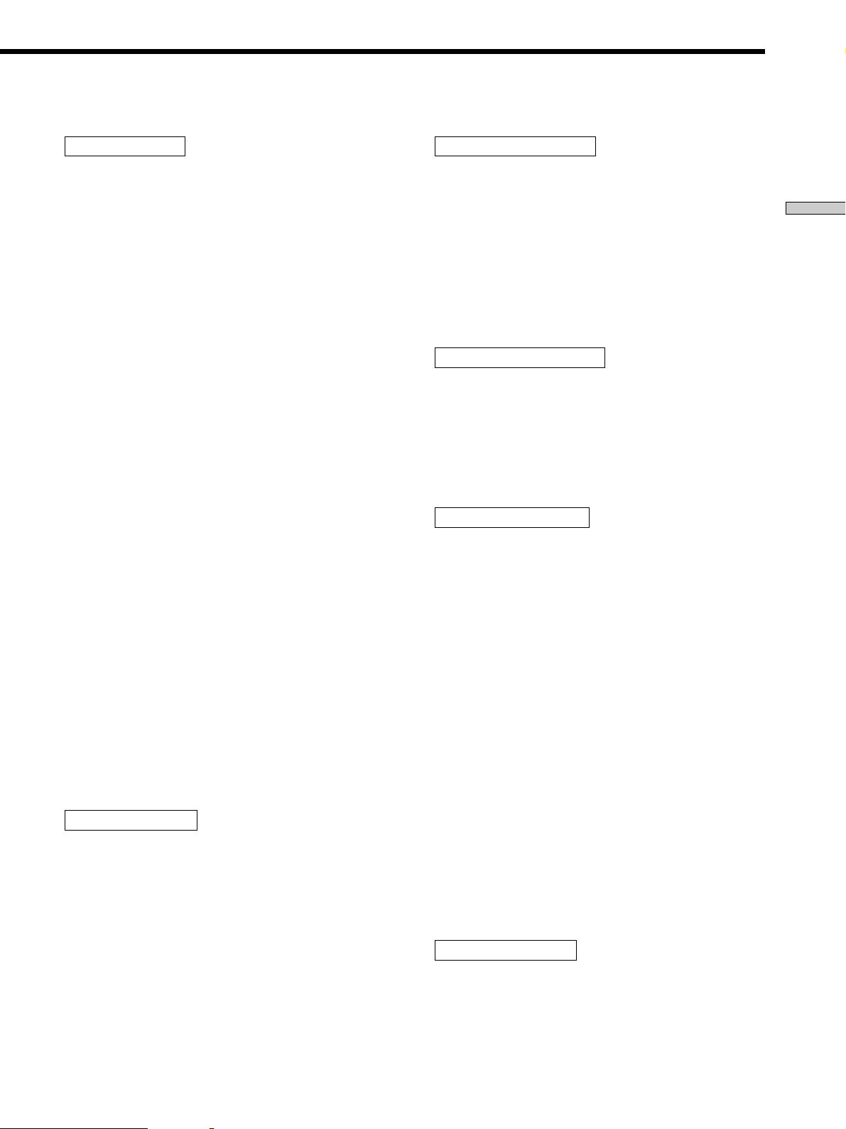
*1~*3 correspond to the following Dolby Pro Logic modes
*1 NORMAL
*2 PHANTOM
*3 3 STEREO
(*2 + *3 = 2ch mode).
z
About speaker sizes (LARGE and SMALL)
Internally, the LARGE and SMALL settings for each speaker
determine whether or not the internal sound processor will cut
the bass signal from that channel. When the bass is cut from a
channel, the bass redirection circuitry sends the corresponding
bass frequencies to the sub woofer or other “LARGE” speaker.
However, since bass sounds have a certain amount of
directionality it best not to cut them, if possible. Therefore, even
when using small speakers, you can set them to “LARGE” if you
want to output the bass frequencies from that speaker. On the
other hand, if you are using a large speaker, but prefer not to
have bass frequencies output from that speaker, set it to
“SMALL”.
If the overall sound level is lower than you prefer, set all speakers
to “LARGE”. If there is not enough bass, you can use the
equalizer to boost the bass levels. To adjust the equalizer, see
page 39.
3
p Sub woofer selection
SUB WOOFER [YES]
Initial setting : YES
• If you connect a sub woofer, select “YES”.
• If you do not connect a sub woofer, select “NO”. This
activates the bass redirection circuitry and outputs the
LFE signals from other speakers.
• In order to take full advantage of the bass redirection
circuitry, we recommend setting the sub woofer’s cut off
frequency as high as possible.
p Front speaker distance
FRONT XX feet* (meter)
Initial setting : 16 feet* (5.0 meter)
Set the distance from your listening position to the front
(left or right) speaker (A on page 18).
• Front speaker distance can be set in 1 foot* (0.1 meter)
steps from 3 to 40 feet* (1.0 to 12.0 meters).
• If both speakers are not placed an equal distance from
your listening position, set the distance to the closest
speaker.
* U.S.A./Canada models only.
p Center speaker distance
CENTER XX feet* (meter)
Initial setting : 16 feet* (5.0 meter)
Set the distance from your listening position to the center
speaker.
• Center speaker distance can be set in 1 foot* (0.1 meter)
steps from 3 to 40 feet* (1.0 to 12.0 meters).
* U.S.A./Canada models only.
p Rear speaker distance
REAR XX feet* (meter)
Initial setting : 11 feet* (3.5 meter)
Set the distance from your listening position to the rear
(left or right) speaker.
• Rear speaker distance can be set in 1 foot* (0.1 meter)
steps from 3 to 40 feet* (1.0 to 12.0 meters).
• If both speakers are not placed an equal distance from
your listening position, set the distance to the closest
speaker.
* U.S.A./Canada models only.
z
About speaker distances
Please note that, setting the speaker distance closer than the
actual location of the speakers will cause a delay in the output of
the sound from that speaker. In other words, the speaker will
sound like it is farther away.
For example, setting the center speaker distance 3~6 feet
(1~2 meters) closer than the actual speaker position will create a
fairly realistic sensation of being “inside” the screen. If you
cannot obtain a satisfactory surround effect because the rear
speakers are too close, setting the rear speaker distance closer
(shorter) than the actual distance will create a larger soundstage.
Adjusting these parameter while listening to the sound often
results in much better surround sound. Give it a try!
p Sub woofer distance
S.W XX feet* (meter)
Initial setting : 16 feet* (5.0 meter)
Set the distance from your listening position to the sub
woofer.
• Sub woofer distance can be set in 1 foot* (0.1 meter)
steps from 3 to 40 feet* (1.0 to 12.0 meters).
* U.S.A./Canada models only.
Hooking Up and Setting Up the Speaker System
19
Page 20
Multi Channel Surround Setup
p Sub woofer phase polarity
S.W PHASE [NORMAL]
Initial setting : NORMAL
Set the sub woofer phase polarity.
There is usually no problem when the sub woofer phase
Hooking Up and Setting Up the Speaker System
polarity is set to "NORMAL". However, depending on the
type of front speakers, the position of the sub woofer, and
the cut-off frequency of the sub woofer, setting the phase
polarity to "REVERSE" may produce better bass.
Besides bass reproduction, the richness and tightness of
the overall sound may also be affected. While listening
from the main listening position, select the setting that
best suits your environment.
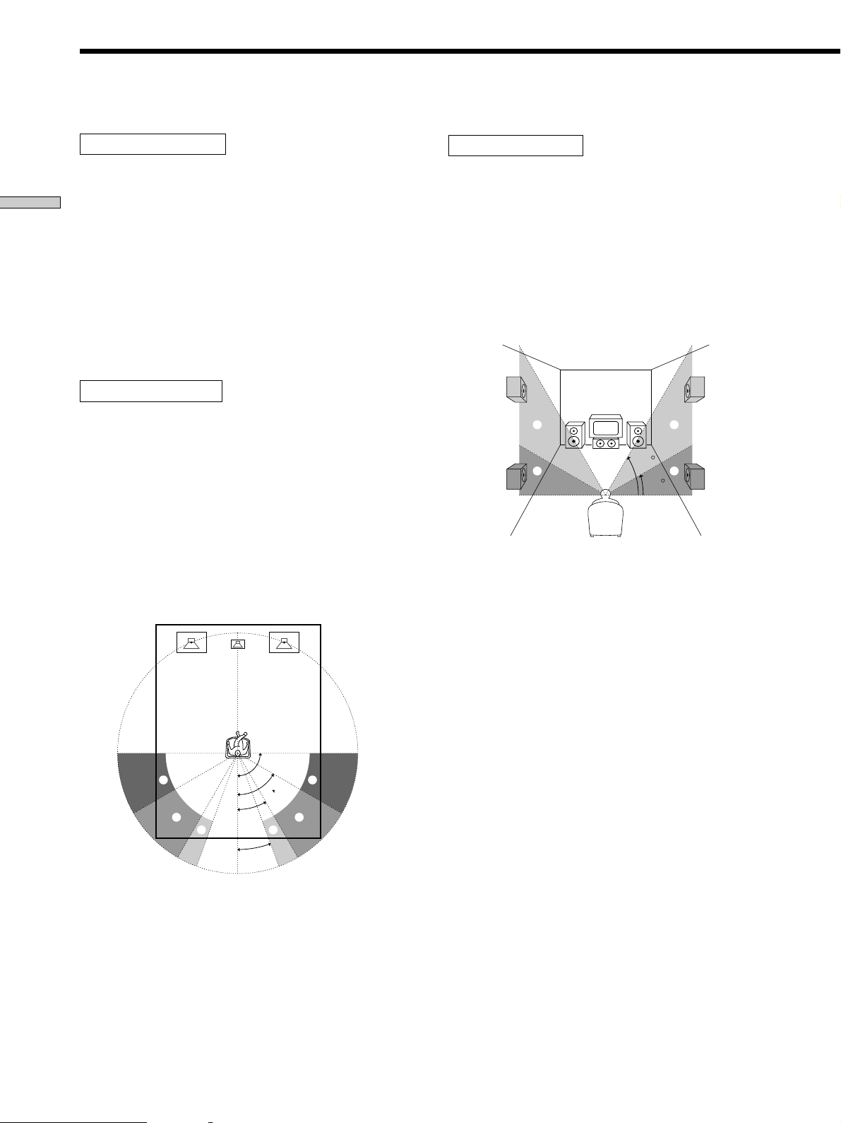
p Rear speaker position*
REAR POSI [BEHIND]
Initial setting : BEHIND
This parameter lets you specify the location of your rear
speakers for proper implementation of the Digital Cinema
Sound “VIRTUAL” sound fields. Refer to the illustration
below.
• Select “SIDE” if the location of your rear speakers
corresponds to section A.
• Select “MIDDLE” if the location of your rear speakers
corresponds to section B.
• Select “BEHIND” if the location of your rear speakers
corresponds to section C.
This setting only effects the “VIRTUAL” sound fields.
p Rear speaker height*
REAR HEIGHT [LOW]
Initial setting : LOW
This parameter lets you specify the height of your rear
speakers for proper implementation of the Digital Cinema
Sound “VIRTUAL” sound fields. Refer to the illustration
below.
• Select “LOW” if the location of your rear speakers
corresponds to section A.
• Select “HIGH” if the location of your rear speakers
corresponds to section B.
This setting only effects the “VIRTUAL” sound fields.
60
B
A
30
B
A
* This parameter is not available when “Rear speaker
size“ is set to “NO”.
z
About the rear speaker position and rear speaker height
These settings are designed specifically for implementation of the
Digital Cinema Sound “VIRTUAL” sound fields.
The rear speaker position parameter allows you to specify one of
three possible horizontal positions. The rear speaker height
parameter allows you to specify one of two possible height
positions. Select the position and height combination that comes
closest to the actual position of your rear speakers.
90°
A
B
30°
C C
20°
60°
A
B
* This parameter is not available when “Rear speaker
size“ is set to “NO”.
20
Page 21

p Front speaker roll off frequency
FRONT SP > XXXHz
Initial setting : > 80 Hz
This setting lets you select the roll off frequency for the
low cut filter of the front (left and right) speakers when
the front speakers are set to “SMALL”.
• The bass frequencies lower than the cut off frequency
are divided by the bass redirection circuitry and output
from the sub woofer or other “LARGE” speakers. In
order to prevent clipping, frequencies below the cut off
frequency are not output from the front speakers.
p Center speaker roll off frequency
CENTER SP > XXXHz
Initial setting : > 80 Hz
This setting lets you select the roll off frequency for the low cut filter
of the center speaker when the center speaker is set to “SMALL”.
• The bass frequencies lower than the cut off frequency
are divided by the bass redirection circuitry and output
from the sub woofer or other “LARGE” speakers. In
order to prevent clipping, frequencies below the cut off
frequency are not output from the center speaker.
p Rear speaker roll off frequency
REAR SP > XXXHz
Initial setting : > 80 Hz
This setting lets you select the roll off frequency for the
low cut filter of the rear (left and right) speakers when the
rear speakers are set to “SMALL”.
• The bass frequencies lower than the cut off frequency
are divided by the bass redirection circuitry and output
from the sub woofer or other “LARGE” speakers. In
order to prevent clipping, frequencies below the cut off
frequency are not output from the rear speakers.
z
About the roll off frequency parameters
These parameters are designed to allow you to prevent clipping
by eliminating output of low-bass frequencies from “SMALL”
speakers. Be sure to set the roll off frequency so that clipping
does not occur from the respective speaker.
p LFE high cut filter
LFE HIGH CUT [STD]
Initial setting: STD (=120 Hz)
This setting lets you select the cutoff frequency of the LFE
channel High Cut Filter. Normally, this should set to STD.
When using a passive subwoofer powered by a separate power
amplifier, it may be better to change the cutoff frequency. When
this is the case, use a setting other than STD.
p Distance unit
DIST.UNIT [feet]* [meter]
Initial setting : feet* (meter)
Lets you select either feet or meters as the unit of measure for
setting distances. 1 foot corresponds to a 1 ms difference.
* U.S.A./Canada models only.
Adjusting the speaker volume
Use the remote while seated in your listening position to
adjust the volume of each speaker.
For more information regarding remote control
operations, refer to the separate manual “Remote
Commander” supplied with this unit.
1 Press 1/u to turn on the receiver.
2 Touch SOUND FIELD on the supplied remote to
display the SOUND FIELD screen.
3 Touch LEVEL on the supplied remote to display the
LEVEL screen.
4 Touch TEST TONE on the supplied remote.
5 Touch + on the remote.
You will hear the test tone from each speaker in
sequence.
6 Adjust the volume level so that the volume of the
test tone from each speaker sounds the same
when you are in your main listening position.
• To adjust the balance of the front right and front left
speakers, use the front balance controls on the
remote (or FRONT (L/R) in the LEVEL menu (page
42)).
• To adjust the balance of the rear right and rear left
speakers, use the rear balance control in the remote
(or REAR (L/R) in the LEVEL menu (page 42)).
• To adjust the volume level of the center speaker, use
the center level control on the remote (or CENTER
LEVEL in the LEVEL menu (page 42)).
• To adjust the volume level of the rear speakers, use
the rear level control on the remote (or REAR
LEVEL in the LEVEL menu (page 42)).
7 Touch EXIT on the remote again to turn off the test
tone.
z
You can adjust the volume level of all speakers at the same
time
Turn MASTER VOLUME on the main unit or touch MASTER
VOLUME +/– on the remote.
z
You can output the test tone from the speaker of your choice
Normally, the test tone is output from each speaker in sequence.
However, you can use the LEVEL menu to output the test tone
from one specific speaker (see page 42). After you have touched
TEST TONE, touch +/– repeatedly to select “fix [XXX]”or “[XXX]
fix”. The test tone is output from the selected speaker.
21
Hooking Up and Setting Up the Speaker System
Page 22
PHONES
SPEAKERS
A
OFF
A+B
B
MEMORY – + – + A.F.D
FM/AM TUNER PRESET
0
10
MULTI CHANNEL DECODING
OPEN/
CLOSE
MASTER VOLUME
1
9
8
7
2
3
6
5
4
AUDIO SPLIT DIGITAL / ANALOG
1/ u
+
ENTER
EQ SUR LEVEL
TUNER CUSTOM SET UP
VIDEOS-VIDEO
L AUDIO R
MASTER VOLUME
1/u
–
2 CH ANALOG DIRECT EQ BANK 5.1CH INPUT
SOUND FIELD PRESET SOUND FIELD
INPUT
SELECTOR
– +
MODE
INPUT SELECTOR
Multi Channel Surround Setup
Notes
• The rear balance, center level, and rear level are shown in the
display during adjustment.
• Although these adjustments can also be made via the front
panel using the parameters in the LEVEL menu (when the test
Hooking Up and Setting Up the Speaker System
tone is output, the unit switches to the LEVEL menu
automatically), we recommend you follow the procedure
described above and adjust the speaker levels from your
listening position using the remote control.
z
When setting the volume levels for each speaker
Let’s assume that you have matched the sound levels of all the
speakers using the test tone. Although this lays the foundation
for high quality surround sound, it may be necessary to make
further adjustments while listening to playback of actual
software. This is because most software contains center and rear
channels recorded at slightly lower levels than the two front
channels.
When you actually playback software recorded in multi channel
surround you will notice that increasing the center and rear
speaker levels produces a better blend between the front and
center speakers and greater cohesion between the front and rear
speakers. Increasing the level of the center speaker about 1 dB,
and the rear speakers about 1~2 dB is likely to produce better
results.
In other words, in order to create a more cohesive soundstage
with balanced dialog, we recommend that you make some
adjustments while playing your software. Changes of only 1 dB
can make a huge difference in the character of the soundstage.
Before You Use Your Receiver
Before turning on the receiver
Make sure that you have:
• Turned MASTER VOLUME to the leftmost position (0).
• Selected the appropriate front speakers (see “@∞
SPEAKERS selector” on page 27).
Checking the connections
After connecting all of your components to the receiver,
do the following to verify that the connections were made
correctly.
1 Press 1/u to turn on the receiver.
2 Rotate INPUT SELECTOR to select a component
(program source) that you connected (e.g., CD
player or tape deck).
3 Turn on the component and start playing it.
4 Rotate MASTER VOLUME to turn up the volume.
If you do not obtain normal sound output after
performing this procedure, look for the reason in the
checklist on the following page and take the appropriate
measures to correct the problem.
22
Page 23

There is no sound no matter which component is
selected.
/ Check that both the receiver and all components
are turned on.
/ Check that the MASTER VOLUME control is not
set at 0.
/ Check that the SPEAKERS selector is not set to
OFF or to a position for front speakers that are not
connected to the receiver (see “@∞ SPEAKERS
selector” on page 27).
/ Check that all speaker cords are connected
correctly.
/ If “MUTING [ON]” appears in the display, press
MUTING on the remote to turn off the muting
function.
There’s no sound from a specific component.
/ Check that the component is connected correctly to
the audio input jacks for that component.
/ Check that the cord(s) used for the connection is
(are) fully inserted into the jacks on both the
receiver and the component.
No sound is heard from one of the front
speakers.
/ Connect a pair of headphones to the PHONES jack
and set the SPEAKERS selector to OFF to verify
that sound is output from the headphones (see “@∞
SPEAKERS selector” and “PHONES jack” on page
27).
If only one channel is output from the headphones,
the component may not be connected to the
receiver correctly. Check that all the cords are fully
inserted into the jacks on both the receiver and the
component.
If both channels are output from the headphones,
the front speaker may not be connected to the
receiver correctly. Check the connection of the
front speaker which is not outputting any sound.
Hooking Up and Setting Up the Speaker System
If you encounter a problem that is not included above, see
“Troubleshooting” on page 57.
23
Page 24

Location of Parts and Basic Operations
This chapter provides information
about the locations and functions of
the buttons and controls on the front
panel. It also explains basic
operations.
Front Panel Parts Description
1 1/u switch
Press to turn the receiver on and off.
• Before you turn on the receiver, make sure that you have
turned the MASTER VOLUME control to the leftmost
position to avoid damaging you speakers.
2 INPUT SELECTOR control
Turn to select the component you want to use.
To select Turn to light
VCR VIDEO 1, VIDEO 2, or VIDEO 3
DVD player DVD/LD* or DVD
LD player DVD/LD* or TV/LD
Satellite tuner* or TV tuner TV/SAT* or TV/LD
Tape deck TAPE
MD or DAT deck MD/DAT
CD player CD
Tuner TUNER
Turntable PHONO
* U.S.A./Canada models only.
24
After selecting the component, turn on the component
you selected and play the program source.
• After selecting VCR, DVD player, or LD player, turn on the
TV and set the TV’s video input to match the component
you selected.
Page 25

1
1 / u
MULTI CHANNEL DECODING
5
MASTER VOLUME
4
4
5
6
7
8
3
3
2
SPEAKERS
A
B
OFF
A+B
PHONES
FM/ AM TUNER PRESET SOUND FIELD PRESET SOUND FIELD
MEMORY – + – + A.F.D 2 CH ANALOG DIRECT EQ BANK 5.1CH INPUT
L AUDIO R
VIDEOS-VIDEO
3 AUDIO SPLIT button
Press to select and play another audio source in
combination with the selected component.
1 Rotate INPUT SELECTOR to select a video component.
2 Press AUDIO SPLIT repeatedly to select a different audio
source or press AUDIO SPLIT once to display the current
settings and turn the jog dial to select the different audio
source. The display switches to “V:XXX A:XXX” to show
both the video (V:XXX) and audio (A:XXX) sources.
To cancel AUDIO SPLIT
Press and hold AUDIO SPLIT for at least two seconds.
Note
When using AUDIO SPLIT, the input (digital/analog) of the
selected audio source is automatically set to “AUTO” (see
“4 DIGITAL/ANALOG button” for details).
– +
MODE
EQ SUR LEVEL
TUNER CUSTOM SET UP
–
4 DIGITAL/ANALOG button
Press to select either digital or analog audio signals for
your digital components (DVD/LD*, DVD, TV/SAT*,
TV/LD, CD and MD/DAT).
Each press switches the input of the currently selected
component as follows :
Select To
AUTO Give priority to digital signals
ANALOG Specify the analog audio signals
DIGITAL (OPTICAL) Specify the digital audio signals
DIGITAL (COAXIAL) Specify the digital audio signals
* U.S.A./Canada models only.
1
0
INPUT
AUDIO SPLIT DIGITAL / ANALOG
SELECTOR
OPEN/
+
CLOSE
ENTER
9
10
Location of Parts and Basic Operations
2
when there are both digital and
analog connections. If there are
no digital signals, analog is
selected.
input to the AUDIO IN (L and R)
jacks.
input to the DIGITAL OPTICAL
IN jacks.
input to the DIGITAL COAXIAL
IN jack. (CD, DVD/LD* or DVD
only)
5 5.1CH INPUT button
Press to enjoy the audio source connected to the 5.1CH
INPUT jacks. Press again to return to the previous
function. When you want to listen to 5.1 channel audio
with another function, select the function first, and
then press 5.1CH INPUT.
• When 5.1CH INPUT is selected, the equalizer, bass booster,
and sound field effects do not function.
• When 5.1CH INPUT is selected, sound is output from all of
the speakers even if the center and rear speakers are set to
“NO” in the SP SETUP menu.
25
Page 26

Front Panel Parts Description
8
7
6
1 / u
Location of Parts and Basic Operations
A+B
SPEAKERS
OFF
PHONES
A
B
MEMORY – + – + A.F.D
@∞
6 IR emitter
Emits IR signals to the remote.
7 IR receptor
Receives IR signals emitted by the remote.
8 MEMORY button
Press to memorize a preset station or preset sound
field.
9 The following buttons operate the built-in tuner. For
details, see “Receiving Broadcasts” starting from page
48.
TUNER PRESET +/– buttons
Scans all preset stations.
FM/AM button
Selects the FM or AM band.
!º SOUND FIELD PRESET +/– buttons
Press to select a preset sound field.
!¡ MULTI CHANNEL DECODING indicator
This indicator lights when the unit is decoding signals
recorded in a multi channel format.
9
FM/ AM TUNER PRESET
VIDEOS-VIDEO
!º
MULTI CHANNEL DECODING
SOUND FIELD PRESET SOUND FIELD
L AUDIO R
@¢
@£
!¡
!™
– +
MODE
EQ SUR LEVEL
TUNER CUSTOM SET UP
@™
@º
!ª
@¡
!£
2 CH ANALOG DIRECT EQ BANK 5.1CH INPUT
+
–
!•
!¶
!§
ENTER
!¢
MASTER VOLUME
5
4
3
2
1
0
OPEN/
CLOSE
INPUT
SELECTOR
AUDIO SPLIT DIGITAL / ANALOG
!∞
!™ Use the following buttons to enjoy surround sound.
For details, see “Enjoying Surround Sound” starting
from page 28.
A.F.D. button
Press to set the unit to automatically detect the type of
signals being input and perform the proper decoding.
This mode presents the sound as it was recorded/
encoded without adding any effects.
For details, see “AUTO FORMAT DECODING” on
page 32.
MODE +/– buttons
Press repeatedly to select the desired sound field.
For details, see “Selecting a Sound Field” on page 29.
• Sound fields are not compatible with 96 kHz digital audio
signals.
2 CH button
Press to cancel the sound fields and output the sound
of the selected source from only the front left and right
speakers.
For details, see “2 CHANNEL” on page 32.
ANALOG DIRECT button
Press to listen to an analog source without digital
processing by the equalizer, sound field, etc.
For details, see “ANALOG DIRECT” on page 32.
6
7
8
9
10
26
Page 27
!£ EQ BANK button
Press repeatedly to select an equalizer (EQ PRESET
1~5) or turn the equalizer off (EQ PRESET OFF).
z
To maintain the highest fidelity to the original source
Do the following to bypass the sound field and equalizer circuits.
1 Press EQ BANK to turn off the equalizer.
2 • When listening to multi-channel sources, press A.F.D. to turn
off the sound field processing.
• When listening to two channel (stereo) sources, press 2 CH to
bypass the sound field processing.
The result will be a sound that is highly faithful to the program
source.
!¢ MASTER VOLUME control
After turning on the component you selected, turn to
adjust the volume.
!∞ OPEN/CLOSE buttons
Press to open/close the door on the front panel.
Note
The door may suddenly stop if an external force is applied
while it is being opened or closed. When this occurs, do not
attempt to open or close the door by hand. Remove the cause
of the force, then press OPEN/CLOSE again.
If the door stopped while being closed, the door
automatically opens again a few seconds after closing. If the
door stopped while being opened, the door remains where it
stopped.
!§ ENTER button
Press to enter the index name (page 47) and clear
settings.
!¶ Cursor buttons (
/ )
Press to select various speaker level, surround, and
equalizer parameters (etc.).
!• Jog dial
Turn to adjust the selected speaker level, surround,
and equalizer parameters (etc.).
@¡ CUSTOM button
Press to activate custom parameters (page 35).
@™ SUR button
Press to activate the surround parameters (page 35).
You can adjust the various surround parameters (effect
level, wall type, etc.).
@£ TUNER button
Press to activate the tuner menu.
@¢ EQ button
Press to activate the equalizer parameters (page 35).
You can adjust the various equalizer parameters.
@∞ SPEAKERS selector
Set according to the front speakers you want to drive.
Set to To select
A The speakers connected to the FRONT
B The speakers connected to the FRONT
A+B* The speakers connected to both the FRONT
OFF No speaker output
Be sure to connect front speakers with a nominal impedance of 8
*
ohms or higher if you want to select both sets (A+B) of front
speakers
SPEAKERS A terminals
SPEAKERS B terminals
SPEAKERS A and B terminals (parallel
connection)
PHONES jack
Use to connect stereo headphones.
Connecting headphones cuts the output from the PRE
OUT jacks and speaker terminals.
When the headphones are connected, if 2 CH or
AUTO FORMAT DECODING is selected, 2 channel
stereo is output. If any other sound field is selected, it
is automatically changed to “HEADPHONE
THEATER”.
Location of Parts and Basic Operations
!ª SET UP button
Press to activate the setup mode, then use the cursor
buttons (!¶) to select the parameters. You can then
make various settings using the jog dial (!•).
@º LEVEL button
Press to activate the speaker level parameters (page
35). You can adjust the various speaker level
parameters (front balance, rear balance, etc.).
27
Page 28

Enjoying Surround Sound
This chapter describes how to set up
the receiver to enjoy surround sound.
You can enjoy multi channel surround
when playing back software encoded
with Dolby Digital or DTS.
You can take advantage of surround sound simply by
selecting one of the receiver’s pre-programmed sound
modes. They bring the exciting and powerful sound of
movie theaters and concert halls into your home. You can
also customize the sound modes to obtain the sound you
desire by changing the various surround parameters.
The receiver contains a variety of different sound modes.
The cinema sound modes are designed for use when
playing back movie software (DVD, LD, etc.) encoded
with multi channel surround sound or Dolby Pro Logic.
In addition to decoding the surround sound, some of
these modes also provide sound effects commonly found
in movie theaters.
The virtual sound modes contain compelling applications
of the Sony Digital Cinema Sound digital signal
processing technology. They shift the sound away from
the actual speaker locations to simulate the presence of
several “virtual” speakers.
The music (etc.) sound modes are designed for use with
standard audio sources and TV broadcasts. They add
reverberation to the source signal to make you feel as if
you were in a concert hall or stadium (etc.). Use these
sound modes with two-channel sources like CD and
stereo broadcasts of sports programs or musical concerts.
For more information about the sound modes, see pages
30~32.
A.F.D.
The “Auto Format Decoding” sound mode presents the
sound exactly as it was encoded, without adding any
reverberation (etc.).
To fully enjoy surround sound, you must register the
number and location of you speakers. See “Multi-Channel
Surround setup” starting on page 18 to set the speaker
parameters before enjoying surround sound.
28
Page 29
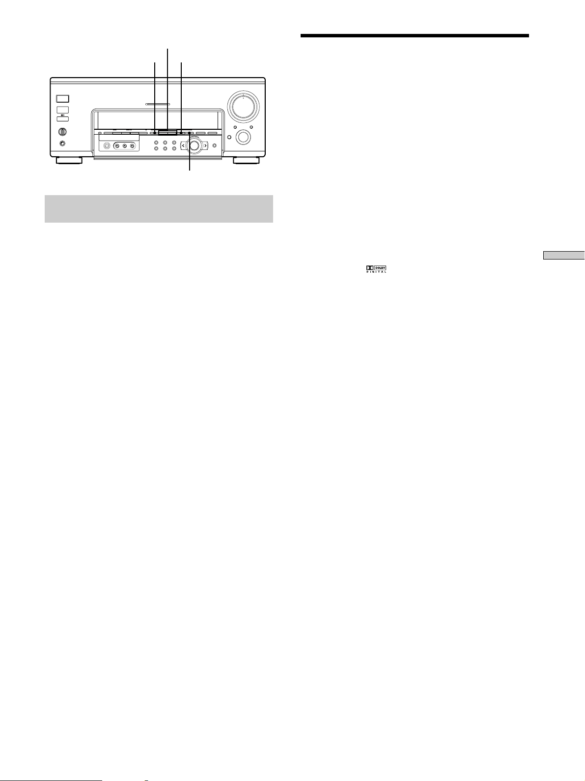
MODE +/–
A.F.D.
2 CH
Selecting a Sound Field
MASTER VOLUME
5
6
4
+
3
2
1
AUDIO SPLIT DIGITAL / ANALOG
OPEN/
CLOSE
ENTER
10
0
INPUT
SELECTOR
1/ u
SPEAKERS
A
B
OFF
A+B
PHONES
FM/AM TUNER PRESET
MEMORY – + – + A.F.D
VIDEOS-VIDEO
MULTI CHANNEL DECODING
SOUND FIELD PRESET SOUND FIELD
L AUDIO R
– +
MODE
EQ SURR LEVEL
TUNER CUSTOM SET UP
2 CH ANALOG DIRECT EQ BANK 5.1CH INPUT
–
ANALOG DIRECT
Brief descriptions of buttons used to
enjoy surround sound
A.F.D. button: Press to set the receiver to automatically
detect the type of audio signal being input and perform
proper decoding (if necessary).
MODE +/– buttons: Press to select the sound field.
2 CH button: Press to output sound from only the front
(left and right) speakers. Multichannel audio signals are
downmixed to 2 channels.
ANALOG DIRECT button: Press to input the analog
signal without digital processing. When this function is
on, the equalizer and sound field (etc.) are turned off.
7
8
9
the pre-programmed sound fields according to the
program you want to listen to.
Press MODE +/– repeatedly to select the sound
field you desire.
The current sound field is indicated in the display.
See the table starting on the following page for
information on each sound field.
To turn the sound field off
You can enjoy surround sound simply by selecting one of
Press the A.F.D. or 2 CH button on the front panel.
For details, see page 26.
z
You can identify Dolby Surround-encoded software by
looking at the packaging
Use discs with the logo. In order to enjoy Dolby Digital
Enjoying Surround Sound
(AC-3) playback you must use discs bearing this logo.
z
When sound signals with a sampling frequency of 96 kHz are
input
The sound signals are output in stereo automatically, and the
sound field is turned off.
z
You can enjoy surround sound while listening to headphones
The PHONES jack on this receiver can present audio in Virtual
Surround. For details, see page 27.
29
Page 30

Selecting a Sound Field
Sound field Effect Notes
NORMAL SURROUND
Software with multi channel surround audio signals is
played according to the way it was recorded.
Software with 2 channel audio signals, is decoded with
Dolby Pro Logic to create surround effects.
CINEMA STUDIO EX. A*
CINEMA STUDIO EX. B*
Enjoying Surround Sound
CINEMA STUDIO EX. C*
SEMI-CINEMA STUDIO EX. A*
SEMI-CINEMA STUDIO EX. B*
Reproduces the sound characteristics of the Sony
Pictures Entertainment “Cary Grant Theater” cinema
production studio using the 3D sound imaging of V.
MULTI DIMENSION (page 31) to create 5 sets of virtual
speakers surrounding the listener from a single pair of
actual rear speakers.
Reproduces the sound characteristics of the Sony
Pictures Entertainment “Kim Novak Theater” cinema
production studio using the 3D sound imaging of V.
MULTI DIMENSION (page 31) to create 5 sets of virtual
speakers surrounding the listener from a single pair of
actual rear speakers.
Reproduces the sound characteristics of the Sony
Pictures Entertainment scoring stage using the 3D
sound imaging of V. MULTI DIMENSION (page 31) to
create 5 sets of virtual speakers surrounding the listener
from a single pair of actual rear speakers.
Reproduces the sound characteristics of the Sony
Pictures Entertainment “Cary Grant Theater” cinema
production studio using the 3D sound imaging of V.
SEMI-M. DIMENSION (page 31) to create 5 sets of
virtual speakers surrounding the listener from the
sound of the front speakers (without using actual rear
speakers).
Reproduces the sound characteristics of the Sony
Pictures Entertainment “Kim Novak Theater” cinema
production studio using the 3D sound imaging of V.
SEMI-M. DIMENSION (page 31) to create 5 sets of
virtual speakers surrounding the listener from the
sound of the front speakers (without using actual rear
speakers).
This is a standard mode, great for
watching most any type of movie.
This mode is ideal for watching sciencefiction or action movies with lots of sound
effects.
This mode is ideal for watching musicals
or classic films where music is featured in
the soundtrack.
LCR
RSLS
LS
RS
RSLS
SEMI-CINEMA STUDIO EX. C*
Reproduces the sound characteristics of the Sony
Pictures Entertainment scoring stage using the 3D
sound imaging of V. SEMI-M. DIMENSION (page 31) to
create 5 sets of virtual speakers surrounding the listener
from the sound of the front speakers (without using
actual rear speakers).
NIGHT THEATER
Allows you to retain a theater like environment while
listening at low volume levels, such as late at night.
MONO MOVIE
Creates a theater like environment from movies with
monaural soundtracks.
STEREO MOVIE
Creates a theater like environment from movies
recorded with stereo soundtracks
HEADPHONE THEATER
Allows you to experience a theater like environment
while listening through a pair of headphones.
Very effective with 5.1ch discreet signal
sources like Dolby Digital and DTS.
* “VIRTUAL” sound field: Sound field with virtual speakers.
However, turning the SUR menu “VIRTUAL SP” parameter off when using “CINEMA STUDIO EX.A~C” or “SEMI-CINEMA STUDIO
EX. A~C” reproduces the sound characteristics of each cinema production studio without virtual speakers.
30
Page 31
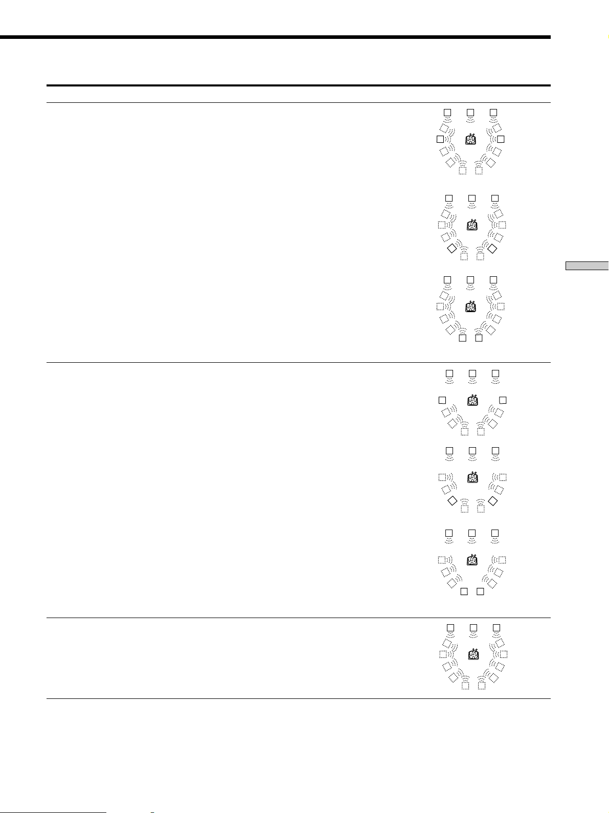
Sound field Effect Notes
V. MULTI DIMENSION*
(Virtual Multi Dimension)
Uses 3D sound imaging to create an array of virtual rear
speakers positioned higher than the listener from a
single pair of actual rear speakers. This mode creates 5
sets of virtual speakers surrounding the listener at
approximately a 30° angle of elevation.
SIDE*
MIDDLE*
LCR
RSLS
LS
LCR
RS
RSLS
RSLS
V. MULTI REAR*
(Virtual Multi Rear)
Uses 3D sound imaging to create 3 sets of virtual rear
speakers from 1 set of actual rear speakers.
BEHIND*
SIDE*
MIDDLE*
LS
LCR
LS
LCR
LS
LCR
LS
LCR
RS
RSLS
RSLS
RS
RSLS
* See
RSLS
RS
RSLS
RSLS
RS
RSLS
Enjoying Surround Sound
page 19
V. SEMI-M. DIMENSION*
(Virtual Semi Multi Dimension)
Uses 3D sound imaging to create virtual rear speakers
from the sound of the front speakers without using
actual rear speakers. This mode creates 5 sets of virtual
speakers surrounding the listener at a 30° angle of
elevation.
* “VIRTUAL” sound field: Sound field with virtual speakers.
BEHIND*
RSLS
LS
LCR
LS
RS
RSLS
* See
RSLS
RS
RSLS
page 19
31
Page 32

Selecting a Sound Field
Sound field Effect Notes
VIRTUAL ENHANCED A*
(Virtual Enhanced Surround A)
Uses 3D sound imaging to create 3 sets of virtual rear
speakers from the sound of the front speakers without
using actual rear speakers.
LCR
RSLS
VIRTUAL ENHANCED B*
(Virtual Enhanced Surround B)
Enjoying Surround Sound
SMALL HALL
LARGE HALL
OPERA HOUSE
JAZZ CLUB
DISCO/CLUB
CHURCH
LIVE HOUSE
ARENA
STADIUM
GAME
Uses 3D sound imaging to create 1 set of virtual rear
speakers from the sound of the front speakers without
using actual rear speakers.
Reproduces the acoustics of a small rectangular concert
hall.
Reproduces the acoustics of a large rectangular concert
hall.
Reproduces the acoustics of an opera house.
Reproduces the acoustics of a jazz club.
Reproduces the acoustics of a discotheque/dance club.
Reproduces the acoustics of a stone church.
Reproduces the acoustics of a 300-seat live house.
Reproduces the acoustics of a 1000-seat concert hall.
Reproduces the feeling of a large open-air stadium.
Obtains maximum audio impact from video game
software.
LCR
RSLS
LS
RS
RSLS
Ideal for soft acoustic sounds.
Ideal for musicals and opera.
Great for rock or pop music.
Great for sporting events or electric
(amplified) music.
Be sure to set the game machine to stereo
mode when using game software with
stereo sound capabilities.
* “VIRTUAL” sound field: Sound field with virtual speakers.
Notes
• The effects provided by the virtual speakers may cause increased noise in the playback signal.
•
When listening to sound fields that employ the virtual speakers, you will not be able to hear any sound coming directly from the rear speakers.
Use the buttons on the front panel to operate the following modes
AUTO FORMAT DECODING
(Press the A.F.D. button)
2 CHANNEL
(Press the 2CH button)
ANALOG DIRECT
(Press the ANALOG DIRECT
button)
Automatically detects the type of audio signal being
input (Dolby Digital, DTS, Dolby Pro Logic, or standard
2 channel stereo) and performs the proper decoding if
necessary. This mode presents the sound as it was
recorded/encoded, without adding any effects.
Outputs the sound from the front left and right
speakers only. Standard two channel (stereo) sources
completely bypass the sound field processing. Multi
channel surround formats are downmixed to two
channels.
The analog input signal is not digitally processed. Only
volume control functions can be used.
You can use this mode as a reference. Set
the equalizer to OFF while using this mode
to hear the source sound exactly as it was
recorded.
This allows you to play any source using
only the front left and right speakers.
This mode is suitable for the enjoyment of
high quality analog audio sources.
Note
No sound is output from the sub woofer when the 2 CHANNEL mode is selected. To listen to two channel (stereo) sources using the front
left and right speakers and a sub woofer, use the AUTO FORMAT DECODING mode.
32
Page 33
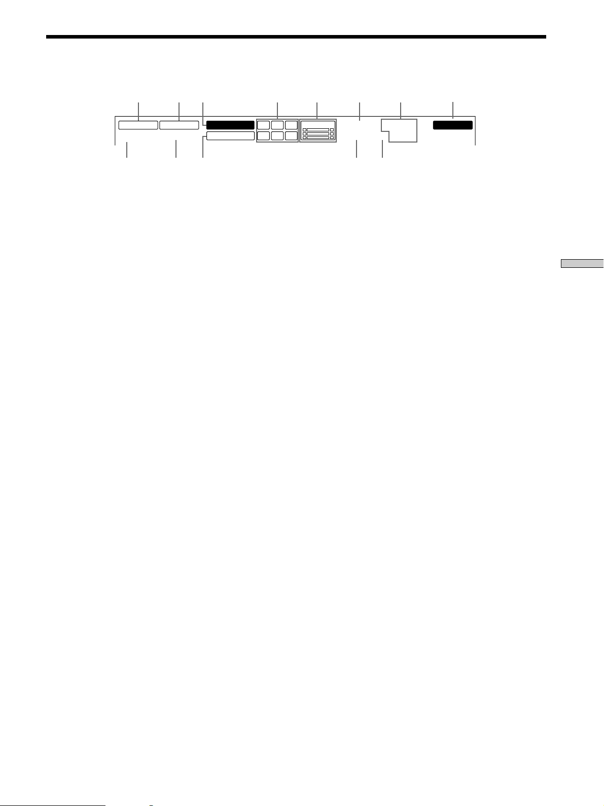
Understanding the Multi-Channel Surround Displays
123 45 67
OPTICAL COAXIAL
MPEGDTSDUAL
a
DIGITAL
a
PRO LOGIC
!™ !¡ !º 9 !£
1 OPTICAL
Lights up when the source signal is a digital signal
being input through the OPTICAL terminal.
2 COAXIAL
Lights up when the source signal is a digital signal
being input through the COAXIAL terminal.
3 a DIGITAL
This indicator lights when the sound field is on and
the unit is decoding signals recorded in the Dolby
Digital (AC-3) format.
4 Playback channel indicators
The letters light to indicate the channels being played
back.
L: Front Left R: Front Right
C: Center LS: Left Surround
RS: Right Surround
S: Surround (monaural or the rear components
obtained by Pro Logic processing)
The boxes around the letters light to indicate the
speakers used to playback the channels.
See the next page for details regarding the playback
channel indicators.
5 L.F.E.
The letters “L.F.E.” light up when the disc being
played contains the LFE (Low Frequency Effect)
channel. When the sound of the LFE channel signal is
actually being reproduced, the bars underneath the
letters lights up to indicate the level. Since the LFE
signal is not recorded in all parts of the input signal
the bar indication will fluctuate (and may turn off)
during playback.
L.F.E.LLSCSR
RS
6 S.WOOFER
Lights when the sub woofer selection is set to “YES”
and sound is being output from the sub woofer.
7 Tuner indicators
These indicators light when using the receiver to tune
in radio stations, etc. See pages 48~51 for tuner
operations.
8 MEMORY
Lights when a tuner preset or sound field preset is
saved in memory.
9 D. RANGE
Lights when dynamic range compression is active. See
page 43 to adjust the dynamic range compression.
!º PRO LOGIC
Lights when this unit applies Pro Logic processing to
two channel signals in order to output the center and
surround channel signals.
!¡ DTS
Lights up when DTS signals are input.
Note
When playing a DTS format disc, be sure that you have made
digital connections and that DIGITAL/ANALOG is NOT set
to ANALOG (see 4 on page 25).
!™ a
Lights when Dolby Digital (AC-3) signals are input.
!£ EQ
Lights when using an equalizer from EQ PRESET 1~5.
8
S.WOOFER STEREO RDS
D.RANGE EQ MONO TA NEWS INFO
MEMORY
Enjoying Surround Sound
33
Page 34
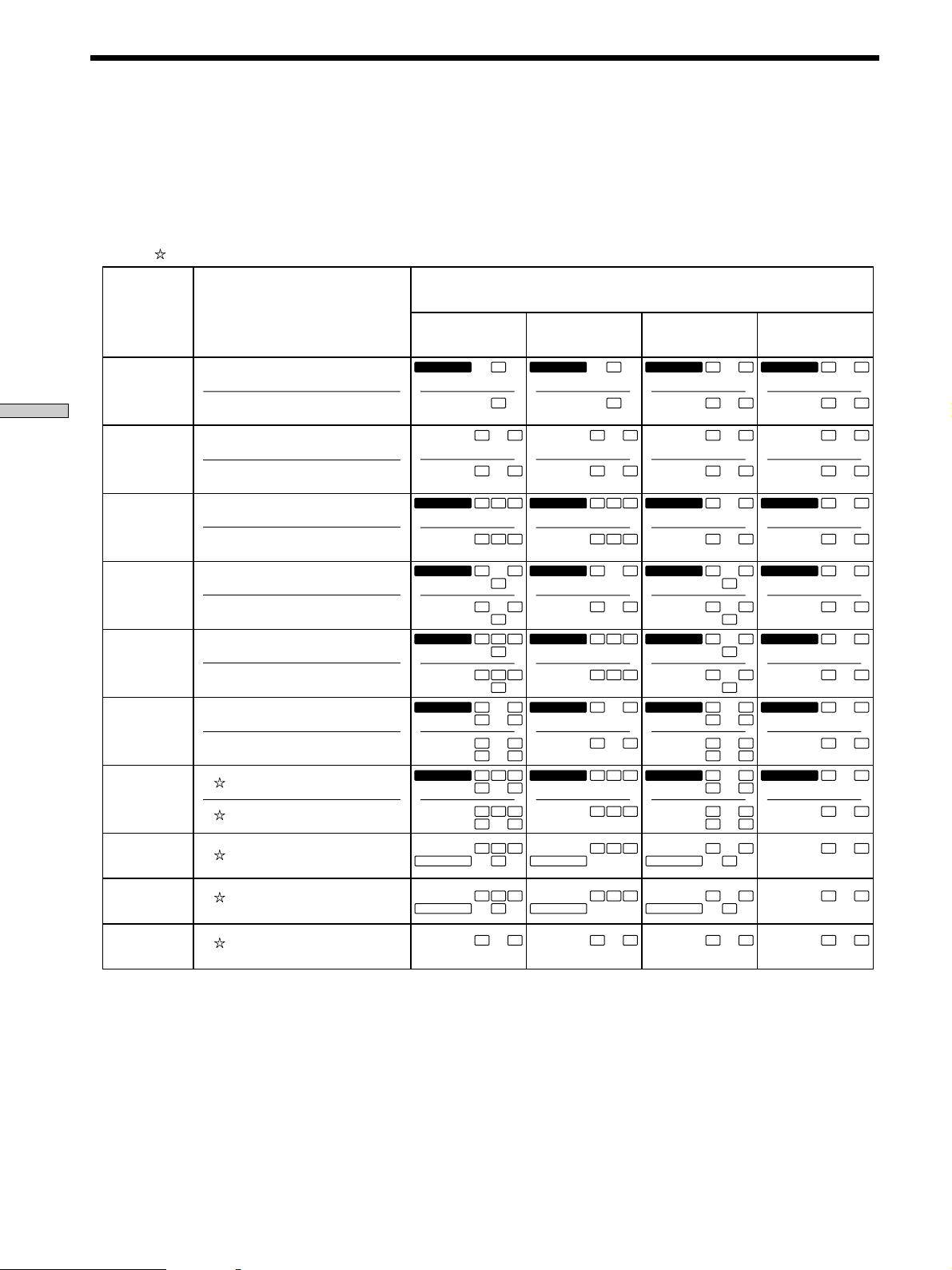
Understanding the Multi-Channel Surround Displays
Source sound displays
The letters (L, C, R, etc.) indicate the source sound. The boxes around the letters vary to show how the receiver downmixes
the source sound (based on the speakers settings). When using music sound modes like LARGE HALL or SMALL HALL
the receiver adds reverberation based on the source sound.
The following table shows how the indicators light when using AUTO FORMAT DECODING mode.
Although the table below shows almost all of the configurations available from multi channel surround signals, the ones
marked “
” are the most common.
(Front/Rear)
Enjoying Surround Sound
Recording
Format
1/0
2/0*
3/0
2/1
3/1
2/2
3/2
2/0**
Input Channel Display
DOLBY DIGITAL [1/0]
DTS [1/0]
DOLBY DIGITAL [2/0]
DTS [2/0]
DOLBY DIGITAL [3/0]
DTS [3/0]
DOLBY DIGITAL [2/1]
DTS [2/1]
DOLBY DIGITAL [3/1]
DTS [3/1]
DOLBY DIGITAL [2/2]
DTS [2/2]
DOLBY DIGITAL [3/2]
DTS [3/2]
DOLBY DIGITAL [2/0]
All speakers
present
DIGITALaC
DTS
DTS
DIGITALaL C R
DTS
DIGITALaLSR
DTS
DIGITALaL CSR
DTS
DIGITALaLLSR
DTS
DIGITALaLLSC R
DTS
PRO LOGIC
Source Sound and Output Channel Display
Rear speakers
absent
DIGITALaC
C
DTS
L R L R L R L R
R
L
C R
L
L
S
CSR
L
L
LS
C R
L
LS
L CSR
R
RS
R
RS
RS
RS
DTS
DTS
DTS
DTS
DTS
DTS
PRO LOGIC
L
DIGITALaL C R
L
DIGITALaL
L
DIGITALaL CSR
L
DIGITALaLLSR
L
LS
DIGITALaLLSC R
L
LS
L CSR
Center speaker
C
DTS
R
DTS
C R
DTS
R
S
R
S
DTS
CSR
DTS
RS
R
RS
DTS
RS
C R
RS
DTS
PRO LOGIC
absent
DIGITALaC
C
R
L
DIGITALaL CR
CR
L
DIGITALaLSR
R
L
S
DIGITALaL CSR
CSR
L
DIGITALaLLSR
DIGITALaLLSCR
L
LS
CR
L
LS
L CSR
RS
R
RS
RS
RS
Rear/center
speakers absent
DIGITALaC
DTS
DTS
DIGITALaL CR
DTS
DIGITALaL
DTS
DIGITALaL CSR
DTS
DIGITALaLLSR
DTS
DIGITALaLLSCR
DTS
PRO LOGIC
C
L
CR
L
S
L
S
CSR
L
L
LS
CR
L
LS
L CSR
R
R
R
RS
R
RS
RS
RS
DOLBY PROLOGIC
PCM XX kHz***
PRO LOGIC
L CSR
L R L R L R L R
PRO LOGIC
L CSR
PRO LOGIC
L CSR
PRO LOGIC
L CSR
* Signals with Dolby surround encoded flag OFF
** Signals with Dolby surround encoded flag ON
*** Sampling frequency is displayed
Notes
• The receiver performs Pro Logic decoding and the display conforms to 2/0** when using the following movie sound modes with 2/0* or
STEREO PCM format signals. (CINEMA STUDIO EX. A, B, C, SEMI-CINEMA STUDIO EX. A, B, C, NIGHT THEATER, V. MULTI
DIMENSION, V. MULTI REAR, V. SEMI-M. DIMENSION, VIRTUAL ENHANCED A, or VIRTUAL ENHANCED B)
• When using music sound modes like LARGE HALL or SMALL HALL with standard audio formats, like PCM, the receiver creates rear
signals from the front L and R signals. However, a center speaker signal is not created. In this case, sound is output from the rear
speakers, but output channel indicators for the rear speakers do not light.
34
Page 35
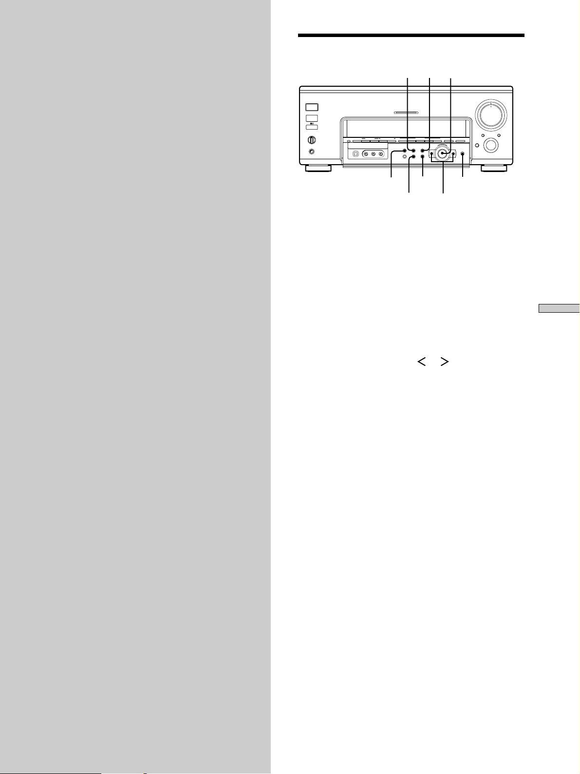
Settings and Adjustments
This chapter describes how to use the
menu operations to change various
settings, adjust the sound fields, and
customize various aspects of the
receiver’s functionality.
Using the Menus
SUR
LEVEL
Jog dial
MASTER VOLUME
5
6
4
7
9
10
0
INPUT
SELECTOR
+
ENTER
3
2
1
AUDIO SPLIT DIGITAL / ANALOG
OPEN/
CLOSE
ENTER
1/ u
SPEAKERS
A
B
OFF
A+B
PHONES
FM/AM TUNER PRESET
MEMORY – + – + A.F.D
VIDEOS-VIDEO
SOUND FIELD PRESET SOUND FIELD
L AUDIO R
EQ
CUSTOM
MULTI CHANNEL DECODING
EQ SUR LEVEL
TUNER CUSTOM SET UP
– +
2 CH ANALOG DIRECT EQ BANK 5.1CH INPUT
MODE
–
SET UP
Cursor buttons
Use the menu operations to adjust various parameters
and customize the receiver to suit your listening
environment, your speaker, your components, and your
personal preferences.
1 Press SET UP, EQ, SUR, LEVEL, or CUSTOM to
display the menu you desire.
See “Menu Function Table” starting on the next page
for a chart showing the menus and their respective
parameters.
8
Settings and Adjustments
2 Press the cursor buttons ( or ) to select the
desired parameter from the selected menu.
3 Turn the jog dial to select the setting you desire.
The new setting becomes effective and is stored
automatically.
4 Repeat steps 1 through 3 to adjust all necessary
parameters.
Notes
• Certain parameters may not be available for adjustment due to
the setting of other parameters (etc.). Unavailable parameters
appear dimmed when shown in the display.
• An EQ BANK (1~5) must be chosen before the EQUALIZER
menu can be adjusted.
35
Page 36
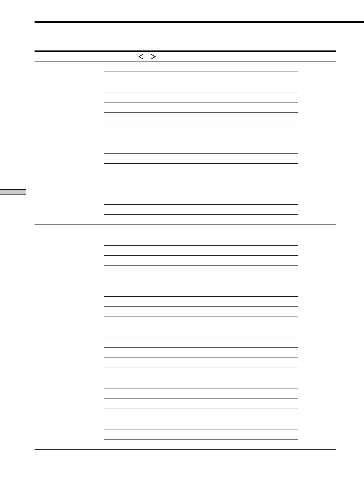
Menu Function Table
Menus (Press)
<SP SETUP> (SET UP) FRONT SP [LARGE] LARGE, SMALL Pages 16~19
Settings and Adjustments
<EQUALIZER> (EQ) FRONT BASS 0 dB From –10.0 to +10.0 dB (in 0.5 dB steps) Pages 39~40
Parameters (Press or to select)
CENTER SP [LARGE] LARGE, SMALL, NO
REAR SP [LARGE] LARGE, SMALL, NO
SUB WOOFER [YES] YES, NO
FRONT 16 feet* (5.0 meter) From 3 to 40 feet* (1.0 to 12.0 m) (in 1 foot* (0.1 m) steps)
CENTER 16 feet* (5.0 meter) From 3 to 40 feet* (1.0 to 12.0 m) (in 1 foot* (0.1 m) steps)
REAR 11 feet* (3.5 meter) From 3 to 40 feet* (1.0 to 12.0 m) (in 1 foot* (0.1 m) steps)
S.W 16 feet* (5.0 meter) From 3 to 40 feet* (1.0 to 12.0 m) (in 1 foot* (0.1 m) steps)
S.W PHASE [NORMAL] NORMAL, REVERSE
REAR POSI [BEHIND] SIDE, MIDDLE, BEHIND
REAR HEIGHT [LOW] HIGH, LOW
FRONT SP > 80 Hz From 40 Hz to 200 Hz (10 Hz steps)
CENTER SP > 80 Hz From 40 Hz to 200 Hz (10 Hz steps)
REAR SP > 80 Hz From 40 Hz to 200 Hz (10 Hz steps)
LFE HIGH CUT STD From 40 Hz to 200 Hz (10 Hz steps, STD = 120 Hz)
DIST. UNIT feet, meter
FRONT BASS 250 Hz From 99 Hz to 1 kHz
FRONT MID 0 dB From –10.0 to +10.0 dB (in 0.5 dB steps)
FRONT MID 1.0 kHz From 198 Hz to 10 kHz
FRONT MID [WIDE] WIDE, MIDDLE, NARROW
FRONT TREBL 0 dB From –10.0 to +10.0 dB (in 0.5 dB steps)
FRONT TREBL 2.5 kHz From 1.0 to 10 kHz
CENTER BASS 0 dB From –10.0 to +10.0 dB (in 0.5 dB steps)
CENTER BASS 250 Hz From 99 Hz to 1 kHz
CENTER MID 0 dB From –10.0 to +10.0 dB (in 0.5 dB steps)
CENTER MID 1.0 kHz From 198 Hz to 10 kHz
CENTER MID [WIDE] WIDE, MIDDLE, NARROW
CENTER TRE. 0 dB From –10.0 to +10.0 dB (in 0.5 dB steps)
CENTER TRE. 2.5 kHz From 1.0 to 10 kHz
REAR BASS 0 dB From –10.0 to +10.0 dB (in 0.5 dB steps)
REAR BASS 250 Hz From 99 Hz to 1 kHz
REAR MID 0 dB From –10.0 to +10.0 dB (in 0.5 dB steps)
REAR MID 1.0 kHz From 198 Hz to 10 kHz
REAR MID [WIDE] WIDE, MIDDLE, NARROW
REAR TREBLE 0 dB From –10.0 to +10.0 dB (in 0.5 dB steps)
REAR TREBLE 2.5 kHz From 1.0 to 10 kHz
PRESET (1~5) clear [NO] NO, YES
Range (Turn the jog dial to select) Description
* U.S.A./Canada models only.
36
Page 37
Menus Parameters Range Description
(Press) (Press or to select) (Turn the jog dial to select)
<SURROUND> (SUR) SURR. EFFECT 100% From 0 to 150% (in 5% steps) Page 41
WALL S____|____H From Soft to Hard
REVERB S____|____L From Short to Long
SCREEN DEPTH [MID] OFF, MID, DEEP
VIRTUAL SP [ON] ON, OFF
REAR ENHANCER [ON] ON, OFF
BASS 0 dB ------- From –10 to +10 dB (in 1 dB steps)
BASS 250 Hz ------- From 99 to 1 kHz
MID 0 dB ------- From –10 to +10 dB (in 1 dB steps)
MID 1.0 kHz ------- From 198 Hz to 10 kHz
MID [WIDE] ------- WIDE, MIDDLE, NARROW
TRE 0 dB ------- From –10 to +10 dB (in 1 dB steps)
TRE 2.5 kHz ------- From 1.0 to 10 kHz
<LEVEL> (LEVEL) TEST TONE [OFF] OFF, AUTO, L, C, R, RS, LS, SW Pages 42~43
FRONT L____|____R L/R 17 step (in 1 dB steps)
REAR L____|____R L/R 17 step (in 1 dB steps)
CENT. LEVEL 0 dB From +10.0 to –20.0 dB, OFF (in 0.5 dB steps)
REAR LEVEL 0 dB From +10.0 to –20.0 dB, OFF (in 0.5 dB steps)
SUB WOOFER 0 dB From +10.0 to –20.0 dB, OFF (in 0.5 dB steps)
LFE MIX 0 dB From +0.0 to –20.0 dB, OFF (in 0.5 dB steps)
dts LFE MIX 0 dB From +10.0 to –20.0 dB, OFF (in 0.5 dB steps)
D. RANGE COMP [OFF] OFF, 0.1 - - - 0.9, STD, MAX
MUTING [OFF] OFF, ON
Settings and Adjustments
37
Page 38
Menu Function Table
Menus Parameters Range Description
(Press) (Press or to select) (Turn the jog dial to select)
<CUSTOMIZE> (CUSTOM) V: (video source) A: (audio source) Page 46~47
Settings and Adjustments
<TUNER> (TUNER) TUNER MODE [AUTO] AUTO, MANUAL Page 49~51
__ : AUDIO [AUTO] AUTO, ANALOG, OPTICAL, COAXIAL
__ : DECODE [AUTO] AUTO, PCM
DISP. DIMMER [100%] 100 - - - 50% (in 10% steps)
ABS PHASE [NORMAL] NORMAL, REVERSE
DF ROLL OFF [STD] STD, SLOW
NOISE BAND [STD] STD, WIDE
2ND AUDIO [SOURCE] SOURCE, TUNER, CD, MD/DAT, TAPE
S.FIELD LINK [OFF] OFF, ON
AUTO FUNCTION [ON] OFF, ON
2-way REMOTE [ON] OFF, ON
XXXXXXXX [ ] select a character to input a name
MEMORY CLEAR [NO] NO, YES
SLEEP [OFF]* OFF, 0:30:00~9:00:00 (in 30 minute steps)
FM MODE [STEREO] STEREO, MONO
FM [-----] A1 input a station name
AM 10 kHz –> 9 kHz [NO]** NO, YES
PRESET CLEAR [NO] NO, YES
* When using the remote, the timer can be adjusted up to 2 hours in 30 minute steps.
** Except for Singapore/Malaysia models.
38
Page 39
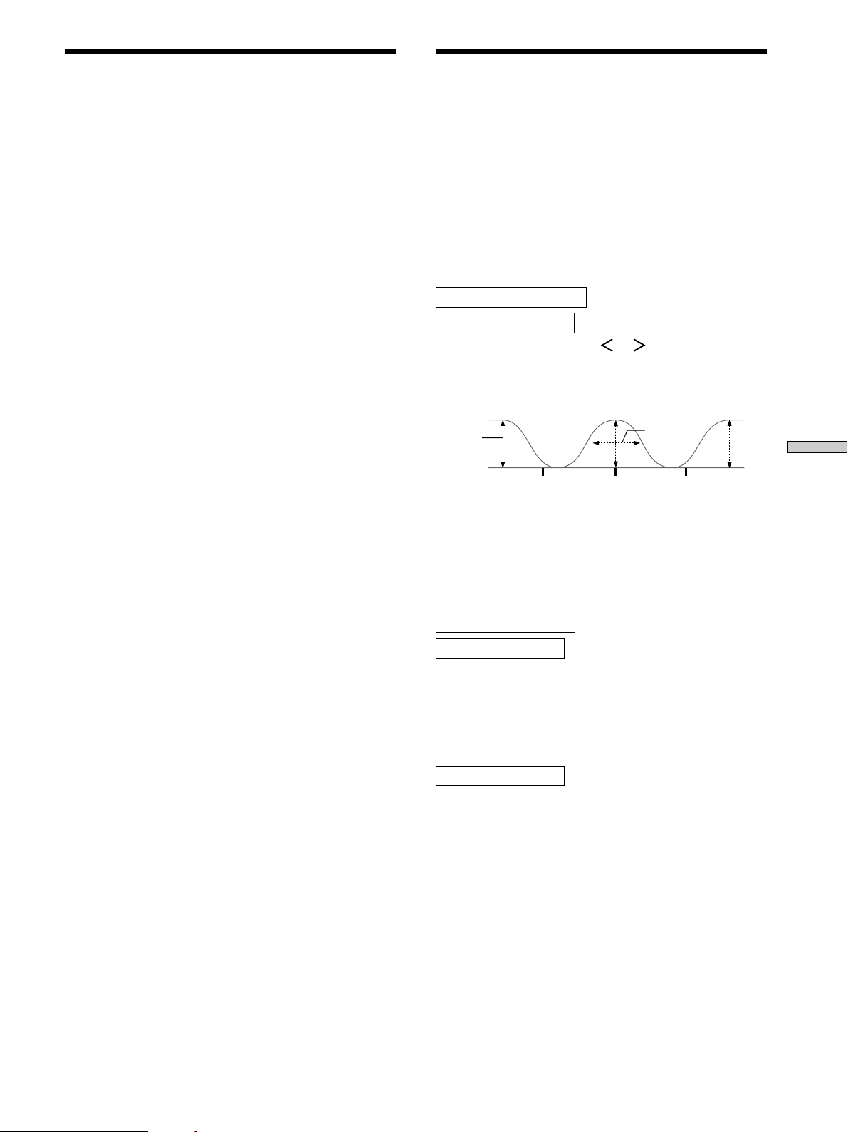
Adjusting the Speaker
Adjusting the Equalization
Settings <SP SETUP>
See “Multi-Channel Surround Setup” on page 18 for
details on the parameters available in the SET UP menu.
p Front speaker size (FRONT SP)
Initial setting : LARGE
p Center speaker size (CENTER SP)
Initial setting : LARGE
p Rear speaker size (REAR SP)
Initial setting : LARGE
p Sub woofer selection (SUB WOOFER)
Initial setting : YES
p Front speaker distance (FRONT)
Initial setting : 16 feet* (5.0 meter)
p Center speaker distance (CENTER)
Initial setting : 16 feet* (5.0 meter)
p Rear speaker distance (REAR)
Initial setting : 11 feet* (3.5 meter)
p Sub woofer distance (S.W)
Initial setting : 16 feet* (5.0 meter)
<EQUALIZER>
The EQUALIZER menu lets you adjust the equalization
(low, mid, and high frequencies) of the front, center, and
rear speakers individually. The equalizer bank lets you
store up to 5 different equalizer settings.
The following menu is only available after pressing EQ
BANK and selecting one of the equalizers (EQ PRESET
1~5).
p Front speaker bass adjustment (Level/
Frequency)
FRONT BASS +XX.XdB
FRONT BASS XXXHz
1 Press the cursor buttons (
the level (dB) or frequency (Hz).
2 Turn the jog dial to adjust.
Repeat until you achieve the sound you desire.
BASS
Level
(dB)
Frequency
(Hz)
• The level can be adjusted ±10 dB in 0.5 dB steps.
• The frequency can be adjusted from 99 Hz to 1 kHz in
21 steps.
or ) repeatedly to select
MID
Band width
Frequency
(Hz)
Frequency
(Hz)
TREBLE
Settings and Adjustments
p Sub woofer phase polarity (S.W PHASE)
Initial setting : NORMAL
p Rear speaker position (REAR POSI)
Initial setting : BEHIND
p Rear speaker height (REAR HEIGHT)
Initial setting : LOW
p Front speaker roll off frequency (FRONT SP >)
Initial setting : 80 Hz
p Center speaker roll off frequency (CENTER SP >)
Initial setting : 80 Hz
p Rear speaker roll off frequency (REAR SP >)
Initial setting : 80 Hz
p LFE high cut filter (LFE HIGH CUT)
Initial setting : STD
p Distance unit (DIST. UNIT)
Initial setting : feet* (meter)
* U.S.A./Canada models only
p Front speaker midrange adjustment (Level/
Frequency)
FRONT MID +XX.XdB
FRONT MID XXXHz
Adjust as described in “Front speaker bass adjustment”.
• The level can be adjusted ±10 dB in 0.5 dB steps.
• The frequency can be adjusted from 198 Hz to 10 kHz in
37 steps.
p Front speaker midrange bandwidth
FRONT MID [WIDE]
This parameter lets you adjust the width of the midrange
band.
• “WIDE” provides a wide band centered on the selected
frequency, for general adjustments.
• “MIDDLE” provides a normal band.
• “NARROW” provides a narrow band centered on the
selected frequency, for specific adjustments.
39
Page 40

Adjusting the Equalization <EQUALIZER>
p Front speaker treble adjustment (Level/
Frequency)
FRONT TREBL +XX.XdB
FRONT TREBL XXXHz
Adjust as described in “Front speaker bass adjustment”.
• The level can be adjusted ±10 dB in 0.5 dB steps.
• The frequency can be adjusted from 1.0 kHz to 10 kHz
in 23 steps.
p Center speaker bass adjustment (Level/
Frequency)
CENTER BASS +XX.XdB
CENTER BASS XXXHz
Adjust as described in “Front speaker bass adjustment”.
• The level can be adjusted ±10 dB in 0.5 dB steps.
• The frequency can be adjusted from 99 Hz to 1 kHz in
21 steps.
Settings and Adjustments
p Center speaker midrange adjustment (Level/
Frequency)
CENTER MID +XX.XdB
CENTER MID XXXHz
Adjust as described in “Front speaker bass adjustment”.
• The level can be adjusted ±10 dB in 0.5 dB steps.
• The frequency can be adjusted from 198 Hz to 10 kHz in
37 steps.
p Rear speaker bass adjustment (Level/
Frequency)
REAR BASS +XX.XdB
REAR BASS XXXHz
Adjust as described in “Front speaker bass adjustment”.
• The level can be adjusted ±10 dB in 0.5 dB steps.
• The frequency can be adjusted from 99 Hz to 1 kHz in
21 steps.
p Rear speaker midrange adjustment (Level/
Frequency)
REAR MID +XX.XdB
REAR MID XXXHz
Adjust as described in “Front speaker bass adjustment”.
• The level can be adjusted ±10 dB in 0.5 dB steps.
• The frequency can be adjusted from 198 Hz to 10 kHz in
37 steps.
p Rear speaker midrange bandwidth
REAR MID [WIDE]
This parameter lets you adjust the width of the midrange
band.
• “WIDE” provides a wide band centered on the selected
frequency, for general adjustments.
• “MIDDLE” provides a normal band.
• “NARROW” provides a narrow band centered on the
selected frequency, for specific adjustments.
p Center speaker midrange bandwidth
CENTER MID [WIDE]
This parameter lets you adjust the width of the midrange
band.
• “WIDE” provides a wide band centered on the selected
frequency, for general adjustments.
• “MIDDLE” provides a normal band.
• “NARROW” provides a narrow band centered on the
selected frequency, for specific adjustments.
p Center speaker treble adjustment (Level/
Frequency)
CENTER TRE. +XX.XdB
CENTER TRE. XXXHz
Adjust as described in “Front speaker bass adjustment”.
• The level can be adjusted ±10 dB in 0.5 dB steps.
• The frequency can be adjusted from 1.0 kHz to 10 kHz
in 23 steps.
p Rear speaker treble adjustment (Level/
Frequency)
REAR TREBLE +XX.XdB
REAR TREBLE XXXHz
Adjust as described in “Front speaker bass adjustment”.
• The level can be adjusted ±10 dB in 0.5 dB steps.
• The frequency can be adjusted from 1.0 kHz to 10 kHz
in 23 steps.
p Preset clear (PRESET x clear)
PRESET 1 clear [YES]
Initial setting : NO
To clear the currently selected equalizer preset, select
[YES] and press ENTER. “Are you sure?” is displayed. If
you select [YES] and press ENTER again and wait a few
seconds, the unit clears the current equalizer and resets it
to the factory preset. “PRESET x CLEARED !” is displayed
as confirmation. (“x” is the number of the current
equalizer preset.)
40
Page 41
Customizing Sound Fields <SURROUND>
The SURROUND menu contains parameters that let you
customize various aspects of the current sound field. The
settings available in this menu are stored individually for
each sound field.
p Effect Level
SURR.EFFECT XXX%
Initial setting : (depends on sound mode)
This parameter lets you adjust the “presence” of the
current digital cinema sound surround effect.
p Wall type
WALL S____|____H
Initial setting : midpoint
When sound is reflected off soft material, such as a
curtain, the high frequency elements are reduced. A hard
wall is highly reflective and does not significantly effect
the frequency response of the reflected sound. This
parameter lets you control the level of the high
frequencies to alter the sonic character of your listening
environment by simulating a softer (S) or harder (H) wall.
The midpoint designates a neutral wall (made of wood).
p Reverberation
REVERB S____|____L
Initial setting : midpoint
Before sound reaches our ears, it is reflected
(reverberated) many times between the left and right
walls, ceiling, and floor. In a large room, sound takes more
time to bounce from one surface to another than in a
smaller room. This parameter lets you control the spacing
of the early reflections to simulate a sonically longer (L) or
shorter (S) time. The midpoint (0) designates a standard
room with no adjustment.
p Screen depth
SCREEN DEPTH [MID]
Initial setting : MID
In a movie theater, sound seems to come from inside the
image reflected on the movie screen. This parameter
allows you to create the same sensation in your listening
room by shifting the sound of the front speakers “into”
the screen.
• The screen depth can be set to OFF, MID, or DEEP.
• DEEP provides the greatest amount of screen depth.
p Virtual speakers
VIRTUAL SP [ON]
Initial setting : ON
Allows you to turn the virtual speakers created by the
CINEMA STUDIO EX. A, B, C and SEMI-CINEMA
STUDIO EX. A, B, C sound fields off or on.
p Rear reflection enhancer
REAR ENHANCER [ON]
Initial setting : ON
This is a setup that adds the effect of a broader sound
obtained from the sound of the surround channel even
when the surround channel sound is monaural. This
setting operates in CINEMA STUDIO EX. A, B, C and
SEMI-CINEMA STUDIO EX. A, B, C.
• When ON is set, the effect is automatically applied to
sources recorded in Dolby Pro Logic or Dolby Digital
[2/1], [3/1] surround channel
• When OFF is set, there is no effect added.
p Bass adjustment (Level/Frequency)
BASS +XXdB
BASS XXXHz
Unlike the equalizer in the equalizer menu (which allows
you to individually adjust the overall sound quality of
each set of speakers) these parameters allow you to
individually adjust the tonal quality of each sound field.
1 Press the cursor buttons (
the level (dB) or frequency (Hz).
2 Turn the jog dial to adjust.
Repeat until you achieve the sound you desire.
• The level can be adjusted ±10 dB in 1 dB steps.
• The frequency can be adjusted from 99 Hz to 1 kHz in
21 steps.
p Midrange adjustment (Level/Frequency)
MID +XXdB
MID XXXHz
Adjust as described in “Bass adjustment”.
• The level can be adjusted ±10 dB in 1 dB steps.
• The frequency can be adjusted from 198 Hz to 10 kHz in
37 steps.
p Midrange bandwidth
MID [WIDE]
This parameter lets you adjust the width of the midrange
band.
• “WIDE” provides a wide band centered on the selected
frequency, for general adjustments.
• “MIDDLE” provides a normal band.
• “NARROW” provides a narrow band centered on the
selected frequency, for specific adjustments.
p Treble adjustment (Level/Frequency)
TREBLE +XXdB
TREBLE XXXHz
Adjust as described in “Bass adjustment”.
• The level can be adjusted ±10 dB in 1 dB steps.
• The frequency can be adjusted from 1.0 kHz to 10 kHz
in 23 steps.
or ) repeatedly to select
41
Settings and Adjustments
Page 42
Adjusting the Speaker Levels <LEVEL>
The LEVEL menu contains parameters that let you modify
the output level of each speaker and perform a variety of
other adjustments to control the sound mix. The settings
available in this menu effect all the sound fields.
z
Most of these settings can also be adjusted directly using
the remote. See “Adjusting the speaker volume” (page 21).
p Test Tone
TEST TONE [OFF]
Initial setting : OFF
Lets you turn the test tone on or off.
• When OFF is set, the test tone is not output.
• [AUTO] outputs the test tone from each speaker in
order automatically.
• L (left front), C (center), R (right front), RS (right
surround), LS (left surround), or SW (sub woofer)
outputs the test tone only from the corresponding
speaker.
Settings and Adjustments
• The test tone can also be output using the supplied
remote. See “Adjusting the speaker volume” (page 21).
p Front balance
FRONT L____|____R
Initial setting : center
Lets you adjust the balance between the front left and
right speakers.
• This setting can also be adjusted directly using the
supplied remote. See “Adjusting the speaker volume”
(page 21).
p Rear Balance
REAR L____|____R
Initial setting : center
Lets you adjust the balance between the rear left and right
speakers.
• This setting can also be adjusted directly using the
supplied remote. See “Adjusting the speaker volume”
(page 21).
p Rear level
REAR LEVEL –XX.XdB
Initial setting : 0 dB
Lets you adjust level of the rear (left and right) speakers.
• The level can be adjusted in 1 dB steps from –20 dB to
+10 dB.
• This setting can also be adjusted directly using the
supplied remote. See “Adjusting the speaker volume”
(page 21).
p Sub woofer level
SUB WOOFER –XX.XdB
Initial setting : 0 dB
Lets you adjust the level of the sub woofer.
• The level can be adjusted in 1 dB steps from –20 dB to
+10 dB.
p LFE (Low Frequency Effect) mix level
LFE MIX –XX.XdB
Initial setting : 0 dB
This parameter lets you attenuate the level of the LFE
(Low Frequency Effect) channel output from the sub
woofer without effecting the level of the bass frequencies
sent to the sub woofer from the front, center or rear
channels via the Dolby Digital (AC-3) bass redirection
circuitry.
• The level can be adjusted in 0.5 dB steps from –20 dB to
0 dB (line level). 0 dB outputs the full LFE signal at the
mix level determined by the recording engineer.
• Selecting OFF mutes the sound of the LFE channel from
the sub woofer. However, the low frequency sounds of
the front, center, or rear speakers are output from the
sub woofer according to the settings made for each
speaker in the speaker setup (page 18~21).
p Center level
CENT.LEVEL –XX.XdB
Initial setting : 0 dB
Lets you adjust level of the center speaker.
• The level can be adjusted in 1 dB steps from –20 dB to
+10 dB.
• This setting can also be adjusted directly using the
supplied remote. See “Adjusting the speaker volume”
(page 21).
42
Page 43
p dts LFE (Low Frequency Effect) mix level
dts LFE MIX XX.XdB
Initial setting : 0 dB
This parameter lets you attenuate the level of the LFE
(Low Frequency Effect) channel output from the sub
woofer without effecting the level of the bass frequencies
sent to the sub woofer from the front, center or rear
channels via the “dts” bass redirection circuitry.
• The level can be adjusted in 0.5 dB steps from +10.0 dB
to –20.0 dB (line level).
• Selecting OFF mutes the sound of the LFE channel from
the sub woofer. However, the low frequency sounds of
the front, center, or rear speakers are output from the
sub woofer according to the settings made for each
speaker in the speaker setup (page 18~21).
z
About the level differences in the LFE MIX settings
The “dts LFE MIX” level is set to +10.0 dB and “LFE MIX” (Dolby
Digital) is set to 0 dB. This is because there is an initial difference
of 10 dB in the overall mix between the Dolby Digital and dts
LFE channel levels. Essentially, with the “dts LFE MIX” level set
to +10 dB and the “LFE MIX (Dolby Digital)” level set to 0 dB,
approximately the same amounts of LFE channel signal are
distributed to the other audio channels in the overall mix.
p Muting
MUTING [OFF]
Initial setting : OFF
Lets you mute the sound (same as MUTING on the
remote).
• ON to mutes the sound from all speakers.
• OFF restores the sound to the original volume.
Settings and Adjustments
p Dynamic range compressor
D. RANGE COMP [OFF]
Initial setting : OFF
Lets you compress the dynamic range of the sound track.
This may be useful when you want to watch movies at
low volumes late at night.
• OFF reproduces the sound track with no compression.
• 0.1 ~ 0.9 allow you to compress the dynamic range in
small steps to achieve the sound you desire.
• STD reproduces the sound track with the dynamic
range intended by the recording engineer.
• MAX provides a dramatic compression of the dynamic
range.
Note
Dynamic range compression is only possible with Dolby Digital
sources.
z
About the Dynamic Range Compressor
This parameter allows you to compress the dynamic range of the
soundtrack based on the dynamic range information included in
the Dolby Digital signal. “STD” is standard compression, but
because many sources have only light compression, you may not
notice much difference when using 0.1~0.9.
Therefore, we recommend using the “MAX” setting. This greatly
compresses the dynamic range and allows you to view movies
late at night at low volumes. Unlike analog limiters, the levels are
predetermined and provide a very natural compression.
43
Page 44
Adjusting the Speaker Levels <LEVEL>
Adjustable parameters for each sound field
2CH
A.F.D.
NORMAL SURROUND r
CINEMA STUDIO EX. A rrrr
CINEMA STUDIO EX. B rrrr
CINEMA STUDIO EX. C rrrr
SEMI-CINEMA STUDIO EX. A rrrr
SEMI-CINEMA STUDIO EX. B rrrr
SEMI-CINEMA STUDIO EX. C rrrr
Settings and Adjustments
NIGHT THEATER rrr r
MONO MOVIE rrr r
STEREO MOVIE rrr r
V. MULTI DIMENSION r
V. MULTI REAR r
V. SEMI-M. DIMENSION r
VIRTUAL ENHANCED A r
VIRTUAL ENHANCED B r
SMALL HALL rrr r
LARGE HALL rrr r
OPERA HOUSE rrr r
JAZZ CLUB rrr r
DISCO/CLUB rrr r
CHURCH rrr r
LIVE HOUSE rrr r
ARENA rrr r
STADIUM rrr r
GAME rrr r
HEADPHONE THEATER r
5.1CH INPUT
ANALOG DIRECT
<SURROUND>
1)
EFFECT WALL REVERB SCREEN VIRTUAL SUR
LEVEL TYPE TIME DEPTH SPEAKER EQ
1) Settings are memorized for each sound field.
44
Page 45
Adjustable parameters for each sound field (continued)
<LEVEL>
FRONT REAR REAR CENTER WOOFER LFE
2)
D.RANGE
BAL. BAL. LEVEL LEVEL LEVEL MIX COMP.
2CH rrr
A.F .D. rrrrrrr
NORMAL SURROUND rrrrrrr
CINEMA STUDIO EX. A rrrrrrr
CINEMA STUDIO EX. B rrrrrrr
CINEMA STUDIO EX. C rrrrrrr
SEMI-CINEMA STUDIO EX. A r rrrr
SEMI-CINEMA STUDIO EX. B r rrrr
SEMI-CINEMA STUDIO EX. C r rrrr
NIGHT THEA TER rrrrrrr
MONO MOVIE rrrrrrr
STEREO MOVIE rrrrrrr
V. MULTI DIMENSION rrrrrrr
V. MULTI REAR rrrrrrr
V. SEMI-M. DIMENSION r rrrr
VIRTUAL ENHANCED A r rrrr
VIRTUAL ENHANCED B r rrrr
SMALL HALL
LARGE HALL
OPERA HOUSE
JAZZ CLUB
DISCO/CLUB
CHURCH
LIVE HOUSE
ARENA
STADIUM
GAME
3)
3)
3)
3)
3)
3)
3)
3)
3)
3)
rrrrrrr
rrrrrrr
rrrrrrr
rrrrrrr
rrrrrrr
rrrrrrr
rrrrrrr
rrrrrrr
rrrrrrr
rrrrrrr
HEADPHONE THEATER r r
5.1CH INPUT
ANALOG DIRECT
Settings and Adjustments
2) Settings are memorized and apply to all sound fields.
3) Sound is not produced from the center speaker for sources with no center channel (Linear PCM, Dolby Digital 2/2, 2/1, 2/0, analog
input).
45
Page 46

Other Settings <CUSTOMIZE>
The CUSTOMIZE menu allows you to customize various
aspects of the receiver’s operation.
p Audio split
V:VIDEO3 A:CD
Use to switch the audio source. (Same as the AUDIO
SPLIT button on the front panel.) See “3 AUDIO SPLIT
button” on page 25 for details.
p Audio input mode
DVD: AUDIO [AUTO]
Initial setting : AUTO
Use to switch the input for the current component. (Same
as the DIGITAL/ANALOG button on the front panel.) See
“4 DIGITAL/ANALOG button” on page 25 for details.
p Digital input decode mode
DVD: DECODE [AUTO]
Settings and Adjustments
Initial setting : AUTO
Lets you specify the type of signal being input to currently
the selected digital audio jack. The settings are stored
independently for each jack.
• AUTO : The unit automatically switches between DTS,
Dolby Digital (AC-3), and PCM.
• PCM : All input signals are treated as PCM signals. If a
Dolby Digital (AC-3), or DTS signal is input to a jack set
to PCM, no sound will be heard. If a jack is set to
“AUTO”, and a CD player or similar component
connected to that jack sounds interrupted when
playback begins, select “PCM” for that jack.
p Display dimmer control
DISP DIMMER XXX%
Initial setting : 100%
Lets you adjust the brightness of the display window.
It can be adjusted in 10% steps from 50 to 100%.
p Phase polarity of the input source
ABS PHASE [NORMAL]
Initial setting : NORMAL
Lets you set the absolute phase polarity of the input
source. Normally, set to [NORMAL]. When outputting the
sound of a source of reverse phase, set to [REVERSE].
When set to [REVERSE], the polarity of the signals output
from all the speakers and PRE OUT jacks is reversed from
the current polarity.
Note
This setting does not change the polarity of the sub woofer to the
front speakers. To change the phase polarity of the sub woofer to
the front speakers, set S.W PHASE to REVERSE in the SP SETUP
menu.
p Digital filter frequency response type
DF ROLL OFF [STD]
Initial setting : STD
Lets you change the digital filter frequency response of
the D/A converter.
• STD: Standard frequency response.
• SLOW : The curve of the treble range is smoother than
with STD. You can enjoy a different sound from STD.
p Test tone noise type
NOISE BAND [STD]
Initial setting : STD
You can change the type of test tone noise.
• STD reproduces a standard test tone with the frequency
response recommended by Dolby Digital.
• WIDE reproduces a “white noise” test tone. You can use
to match the sound of the speakers.
p Sub room hookup
2ND AUDIO [SOURCE]
Initial setting : SOURCE
Lets you output audio signals to a stereo amplifier located
in another room. Select the source to output the audio
signals to the sub room. When [SOURCE] is selected, the
analog signals of the source selected as the function are
output to the sub room.* Be sure to hook up the stereo
amplifier in the sub room to this receiver using the 2ND
AUDIO OUT jacks (see page 11).
* However, if 5.1 CH is selected as the function, the analog
signals of the previously selected source are output to the sub
room.
46
Page 47

p Sound Field Link
S.FIELD LINK [OFF]
Initial setting : OFF
When set to [ON], the sound field that was last applied to
a program source is automatically applied whenever it is
selected. For example, if you listen to CD with STADIUM
as the sound field, change to a different program source,
then return to CD, STADIUM will be applied again. If you
do not want to use this function, set to [OFF].
p CONTROL A1
auto function
AUTO FUNCTION [ON]
Initial setting : ON
Lets you set whether the CONTROL A1
auto function
can turn Sony components connected via CONTROL A1
cord (see page 12) on or off and control their functions as
if in a system or not. Select [OFF] when you do not want
system control of the other components.
p Setting up the 2 way remote
2-way REMOTE [ON]
Initial setting : ON
If you want to use this receiver together with another
component that is also compatible with the 2 way remote
control system, be sure to perform the following operation
to limit response to signals sent from the remote controls.
• To use with the TA-E9000ES, turn OFF
this unit’s 2 way
remote control system. Make sure the TA-E9000ES is
turned on when using this unit.
• To use with other components that have the
turn OFF
the other component’s 2 way remote control
logo,
system. For details, refer to the operating instructions
suppled with your other components.
• To use with Sony CD players CDP-CX260 or
CDP-CX88ES, turn OFF the remote control adapter
switch on the CDP-CX260 or CDP-CX88ES. For details,
refer to the operating instructions suppled with the
CDP-CX260 or CDP-CX88ES.
• When using several 2 way remote control system
components together, be sure to place them close
together in order to enable proper remote operation.
p Naming Program sources
XXXXXXXX [ ]
Lets you register a name of up to 8 characters for the
currently selected function. Touch
or to move the
position and turn the jog dial to select a character. When
you are finished entering the name, press ENTER.
When you want to clear a name that has been registered,
touch
or to make the 8 character boxes blink. Turn
the jog dial one click to the right to make the name appear
as 8 spaces and then press ENTER.
z
You can easily enter the names of components manufactured
by Sony
When or is touched to make the 8 character boxes blink...
• First, turn the jog dial one click to the right to display the name
as 8 spaces. If ENTER is pressed at this time, the name is
cleared.
•If you continue turning the jog dial to the right, the model
names of components manufactured by Sony appear. Press
ENTER to confirm a new name. If you want to make changes to
the name, touch until the character you want to change
blink and turn the jog dial to change the character.
p Memory clear
MEMORY CLEAR [NO]
Initial setting : NO
To clear the memory, select [YES] and press ENTER. “Are
you sure?” is displayed. Select [YES] and press ENTER
again. The unit automatically turns off, and then turns on
again. The memory is cleared.
p Sleep timer
SLEEP X:XX:XX
Initial setting : OFF
Lets you set the receiver to turn off automatically after a
certain time. Simply select how long you would like to
wait before the unit turns itself off. Countdown begins
automatically. The timer can be adjusted in 30 minute
steps up to 9 hours using the receiver and up to 2 hours
using the remote.
To cancel the sleep function, select [OFF] before the count
down is complete.
Settings and Adjustments
47
Page 48

Receiving Broadcasts
This chapter describes how to receive
FM or AM broadcasts and how to
preset selected stations.
You can tune in stations on this receiver in the following
ways:
Automatic/Manual Tuning
If you don’t know the frequency of the station you want,
you can let the receiver scan all available stations in your
area (see page 49). You can also use the jog dial to find the
frequency manually (Manual Tuning).
Preset Tuning
After you have tuned in stations using Direct Tuning or
Automatic Tuning, you can preset them to the receiver
(see page 50). Then you can tune in any of the stations
directly by entering its 2-character code using the
supplied remote (see page 50). Up to 30 FM or AM
stations can be preset. The receiver will also scan all the
stations that you have preset (see page 50).
Direct Tuning Using the Remote
You can enter a frequency of the station you want directly
by using the numeric buttons on the supplied remote (see
page 51).
Before you begin, make sure you have:
• Connected an FM and AM antenna to the receiver (see
page 5).
• Selected the appropriate speaker system (see page 27).
48
Page 49

FM/AM
Automatic/Manual Tuning
MASTER VOLUME
5
6
4
7
+
2
AUDIO SPLIT DIGITAL / ANALOG
OPEN/
CLOSE
ENTER
3
1
8
9
10
0
INPUT
SELECTOR
For details on the buttons used in this section, see “Brief
descriptions of buttons used to receive broadcasts” on this
page.
1 Press FM/AM to select the FM or AM band.
1/ u
SPEAKERS
A
B
OFF
A+B
PHONES
FM/AM TUNER PRESET
MEMORY – + – + A.F.D
VIDEOS-VIDEO
MULTI CHANNEL DECODING
SOUND FIELD PRESET SOUND FIELD
L AUDIO R
– +
MODE
EQ SURR LEVEL
TUNER CUSTOM SET UP
2 CH ANALOG DIRECT EQ BANK 5.1CH INPUT
–
MEMORY
TUNER
ENTER
TUNER
PRESET +/–
Brief descriptions of buttons used to
receive broadcasts
TUNER PRESET +/–: Press to scan all available radio
stations and to scan all preset radio stations.
FM/AM: Press to select the FM or AM band.
MEMORY: Uses for memorizing preset stations.
TUNER: Press to activate the tuner menu.
Tuning scale is:
FM: 50 kHz
AM: U.S.A./Canada models – 10 kHz (to change to 9 kHz, see
page 51.)
Singapore/Malaysia models – 9 kHz
Other models – 9 kHz (to change to 10 kHz, see page 51.)
2 Press TUNER.
The last received station is tuned in.
3 Press the cursor buttons ( or ) to display “TUNE
MODE [AUTO]”.
4 Press TUNER again.
The frequency appears in the display.
5 Turn the jog dial to + or –.
Turn to + to scan from low to high; turn to – to scan
from high to low.
The receiver stops scanning whenever a station is
received.
When the receiver reaches either end of the
band
Scanning is repeated in the same direction.
6 To continue scanning, turn the jog dial to + or –
again.
To perform manual tuning using the jog dial
Press the cursor buttons to display “TUNE MODE [MANUAL]”
in step 3, then press TUNER. You can then use the jog dial to find
the frequency you want.
Receiving Broadcasts
49
Page 50

Preset Tuning
Receiving Broadcasts
For details on the buttons used in this section, see “Brief
descriptions of buttons used to receive broadcasts” on
page 49.
Before tuning to preset stations, be sure to preset them by
performing steps on “Presetting radio stations” below.
Presetting radio stations
1 Turn INPUT SELECTOR to select TUNER.
The last received station is tuned in.
2 Tune in the station that you want to preset using
Automatic/Manual Tuning (page 49) or Direct
Tuning using the remote (page 51).
3 Press MEMORY.
“MEMORY” appears in the display for a few seconds.
Do Steps 4 and 5 before “MEMORY” goes out.
4 Press TUNER PRESET + or – to select a preset
number.
5 Press MEMORY again to store the station.
If “MEMORY” goes out before you can store the
station, start again from Step 3.
Tuning to preset stations
You can tune the preset stations either of the following
two ways.
Scanning the preset stations
1 Turn INPUT SELECTOR to select TUNER.
The last received station is tuned in.
2 Press TUNER PRESET + or TUNER PRESET –
repeatedly to select the preset station you want.
Each time you press the button, the receiver tunes in
one preset station at a time, in the corresponding order
and direction as follows:
nA1˜A2˜...˜A0˜B1˜B2˜...˜B0N
nC0˜...C2˜C1N
6 Repeat Steps 2 to 5 to preset another station.
To change a preset number to another station
Do Steps 1 to 5 to preset the new station to the number.
Clearing preset stations
1 Press TUNER to activate the tuner menu.
2 Press the cursor buttons ( or ) to display
“PRESET CLEAR [NO]”.
3 Turn the jog dial to display “PRESET CLEAR [YES]”
and press ENTER.
“Are you sure? [No]” is displayed.
4 Once again, turn the jog dial to display “[YES]” and
press ENTER.
50
Page 51
Direct Tuning Using the Remote
Use the supplied remote to perform the following
operations.
For details on the buttons used in this section, see the
operationg instructions for the supplied remote.
1 Touch FUNCTION and SUB on the remote to select
TUNER.
The last received station is tuned in.
2 Press FM/AM to select the FM or AM band.
Using the Tuner Menus
See “Automatic/Manual tuning” (page 49), “Preset
Tuning” (page 50) and “Direct Tuning Using the Remote”
(this page) for details.
p Tuning mode setting (TUNE MODE)
Initial setting : AUTO
To tune in receivable stations automatically, select
“AUTO”.
When you want to tune in a station that has a signal too
weak to be tuned in AUTO mode, select “MANUAL” to
change the frequency manually.
3 Touch DIRECT on the remote.
4 Press the numeric buttons to enter the frequency.
Example 1: FM 102.50 MHz
bbbb
Example 2: AM 1350 kHz
(You don’t have to enter the last “0” when the tuning scale is
set to 10 kHz.)
bb
If you cannot tune in a station and the
entered numbers flash
Make sure you’ve entered the right frequency. If not,
repeat Steps 3 and 4.
If the entered numbers still flash, the frequency is not
used in your area.
531
05201
0
b
5 If you’ve tuned in an AM station, adjust the
direction of the AM loop antenna for optimum
reception.
6 Repeat Steps 2 to 5 to receive another station.
z
If you try to enter a frequency that is too precise for the
tuning scale
The entered value is automatically rounded up or down.
p FM mode (FM MODE)
Initial setting : STEREO
Normally, select “STEREO”. If FM stereo reception is
poor, select “MONO”. You will not be able to enjoy the
stereo effect, but the overall sound will be clearer.
p Naming preset stations (FM)
This setting lets you register a name of up to 8 characters
for the currently selected preset station. Touch
move the position and turn the jog dial to select a
character. When you are finished entering the name, press
ENTER. When you want to clear a name that has been
registered, touch
blink. Turn the jog dial one click to the right to make the
name appear as 8 spaces and then press ENTER.
z
You can display the frequency of the station being received
Press TUNER, and then press repeatedly during reception of a
station that has a name registered.
p AM Tuning scale (AM X kHz –> Y kHz)*
Initial setting : NO
You can change the AM tuning scale. Press TUNER to
enter the tuner menu and press
display “AM X kHz n Y kHz”. Turn the jog dial to
display “YES” and press ENTER. When “Are you sure?”
appears in the display, turn the jog dial to select “YES”
and press ENTER again. When you change the AM tuning
scale, AM preset stations are cleared.
or to make the 8 character boxes
or repeatedly to
or to
Receiving Broadcasts
* Except for Singapore/Malaysia models.
p Clearing preset stations (PRESET CLEAR)
Initial setting : NO
51
Page 52
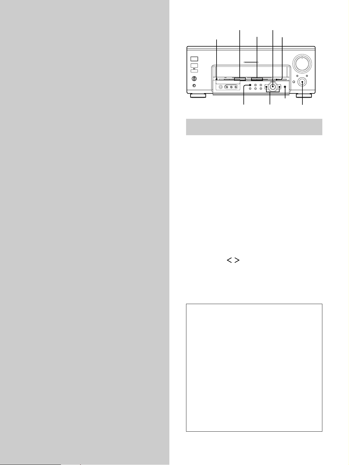
PHONES
SPEAKERS
A
OFF
A+B
B
MEMORY – + – + A.F.D
FM/AM TUNER PRESET
0
10
MULTI CHANNEL DECODING
OPEN/
CLOSE
MASTER VOLUME
1
9
8
7
2
3
6
5
4
AUDIO SPLIT DIGITAL / ANALOG
1/ u
+
ENTER
EQ SUR LEVEL
TUNER CUSTOM SET UP
VIDEOS-VIDEO
L AUDIO R
–
EQ BANK
EQ
2 CH ANALOG DIRECT EQ BANK 5.1CH INPUT
SOUND FIELD PRESET SOUND FIELD
INPUT
SELECTOR
– +
MODE
MODE +/–
SOUND FIELD
PRESET +/–
INPUT SELECTOR
ENTER
MEMORY
Other Operations
This chapter describes the operations
necessary to store your custom
equalization and surround settings for
instant recall.
Jog dial
Cursor buttons
Brief descriptions of buttons used to
create custom equalizer settings
EQ BANK button: Press repeatedly to select the equalizer
you want to adjust.
EQ button: Press to select the parameter you want to
adjust in the current EQ BANK equalizer.
MODE +/– buttons: Press to select the sound field.
MEMORY button: Press to memorize a preset sound
field.
SOUND FIELD PRESET +/– buttons: Press to select a
preset sound field.
INPUT SELECTOR control: Rotate to select the source.
Cursor buttons (
/ ): Use to select parameters after
pressing the EQ button.
Jog dial: Use to adjust parameters and select sound fields
(etc.).
Viewing detailed information about the audio source
You can view information about the audio source currently
selected. When a digital audio source is selected, the
sampling frequency and bit rate of the audio signal can also
be viewed. (Items which can be displayed may differ
depending on the source.)
Turn the jog dial counterclockwise to display the audio
information (except during menu operations). Then turn the
52
jog dial in either direction to scroll the information.
Turning the jog dial immediately after pressing MODE +/–
adjusts surround modes. About two seconds after using
MODE +/– , you can use the jog dial to display the audio
information. Also, after using INPUT SELECTOR, etc., you
can turn the jog dial to display the audio information when
the surround display returns.
Page 53
Presetting Equalizer and Sound Fields
Any changes you make to the preset equalizers (EQ
PRESET 1~5) are stored automatically.
Presetting Equalizer Settings
1 Press EQ BANK repeatedly to select the equalizer
you want to adjust (EQ PRESET 1~5).
2 Press EQ.
3 Press the cursor buttons ( or ) to select the
desired parameter, then turn the jog dial to adjust.
These parameters let you adjust the sound of each
speaker individually (see page 39).
The adjustments are stored automatically.
z
You can turn off the equalization without erasing the
equalizer
Press the EQ BANK repeatedly to select “EQ PRESET OFF”.
Clearing Stored Equalizer Settings
1 Press EQ BANK repeatedly to select the equalizer
you want to clear (EQ PRESET 1-5).
Presetting Sound Fields
You can preset up to 5 of your favorite sound fields and
easily call them up when you want.
1 Press MODE +/– repeatedly to select the sound
field to preset.
2 Press MEMORY.
3 Press SOUND FIELD PRESET +/– to select the preset
number.
4 Press MEMORY.
The sound field is stored in memory.
2 Press EQ.
3 Press the cursor buttons ( or ) to display
“<PRESET x clear [NO]>” (“x” is the number of the
current equalizer preset).
4 Turn the jog dial to display “<PRESET x clear
[YES]>” and press ENTER.
“Are you sure? [NO]” is displayed.
5 Once again, turn the jog dial to display “[YES]” and
press ENTER.
“PRESET x CLEARED !” is displayed and the contents
of the selected equalizer bank are restored to the
factory presets.
Other Operations
53
Page 54

Recording
Your receiver makes it easy to record to and from the
components connected to it. You don’t have to connect
the playback and recording components directly to each
other: once you select a program source on the receiver,
you can record and edit as you normally would using the
controls on each component.
Before you begin, make sure you’ve connected all
components properly.
1/ u
SPEAKERS
A
B
OFF
A+B
PHONES
Other Operations
ç
Playback component
(program source)
ç: Audio signal flow
c: Video signal flow
Recording on an audio tape or MiniDisc
SOUND FIELD PRESET SOUND FIELD
FM/AM TUNER PRESET
MEMORY – + – + A.F.D
L AUDIO R
VIDEOS-VIDEO
c
INPUT SELECTOR
MULTI CHANNEL DECODING
– +
2 CH ANALOG DIRECT EQ BANK 5.1CH INPUT
MODE
EQ SURR LEVEL
TUNER CUSTOM SET UP
+
–
Recording component
(tape deck, MD deck,
VCR)
2
AUDIO SPLIT DIGITAL / ANALOG
OPEN/
CLOSE
ENTER
ç
3
1
MASTER VOLUME
4
0
INPUT
SELECTOR
c
Recording on a video tape
You can record from a VCR, a TV, or an LD player using
the receiver. You can also add audio from a variety of
audio sources when editing a video tape. See your VCR
or LD player’s instruction manual if you need help.
1 Turn INPUT SELECTOR to select the program source
to be recorded.
2 Prepare the component for playing.
5
6
7
8
9
10
For example, insert the laser disc you want to record
into the LD player.
3 Insert a blank video tape into the VCR (VIDEO 1 or
VIDEO 2) for recording.
4 Start recording on the recording VCR, then start
playing the video tape or laser disc you want to
record.
z
You can record the sound from any audio source onto a
video tape while copying from a video tape or laser disc
After locating the point where you want to start recording from
another audio source, select the program source, then start
playback. The audio from that source will be recorded onto the
audio track of the video tape instead of the audio from the
original medium.
You can record on a cassette tape or MiniDisc using the
receiver. See the instruction manual of your tape deck or
MD deck if you need help.
1 Turn INPUT SELECTOR to select the component to
be recorded.
2 Prepare the component for playing.
For example, insert a CD into the CD player.
3 Insert a blank tape or MD into the recording deck
and adjust the recording level, if necessary.
4 Start recording on the recording deck, then start
playback on the playback component.
Notes
• You cannot record a digital audio signal using a component
connected to the analog TAPE REC OUT or MD/DAT REC
OUT jacks. To record a digital audio signal, connect a digital
component to the MD/DAT OPT OUT jack.
• Sound adjustments do not affect the signal output from the
TAPE REC OUT or MD/DAT REC OUT jacks.
• You cannot, however, record multi channel surround digital
signals from a DVD, etc.
For example, if you want to record video from the component
connected to the VIDEO 1 jacks and audio from the component
connected to the CD jacks:
1 Turn INPUT SELECTOR to select VIDEO 1.
2 Press AUDIO SPLIT to display “V:VIDEO1 A:(audio
component)”
3 Press AUDIO SPLIT repeatedly to select the CD player as the
audio component (“V:VIDEO1 A:CD”).
See “3 AUDIO SPLIT button” on page 25 for details on use of
the AUDIO SPLIT button.
To resume audio recording from the original medium, hold down
AUDIO SPLIT for more than 2 seconds to cancel. (Please note
that the selected audio component will switch once before
cancelation.)
Notes
• You cannot record a digital audio signal using a component
connected to the analog TAPE REC OUT, MD/DAT REC OUT,
VIDEO 1 REC OUT or VIDEO 2 REC OUT jacks. To record a
digital audio signal, connect a digital component to the MD/
DAT OPT OUT jack.
• You cannot, however, record multi channel surround digital
signals from a DVD, etc.
54
Page 55
CONTROL A1
CONTROL A1 Control System
Getting Started
This section explains the basic functions of the
CONTROL A1
have special functions, like “CD Synchro Dubbing” on
cassette decks, that require CONTROL A1
connections. For detailed information regarding
specific operations, be sure to also refer to the
Operating Instructions supplied with your
component(s).
The CONTROL A1
simplify the operation of audio systems composed of
separate Sony components. CONTROL A1
provide a path for the transmission of control signals
which enable automatic operation and control features
usually associated with integrated systems.
Currently, CONTROL A1
CD player, amplifier (receiver), MD deck and cassette
deck provide automatic function selection and
synchronized recording.
In the future the CONTROL A1
a multifunction bus allowing you to control various
functions for each component.
Control System. Certain components
Control System was designed to
connections
connections between a Sony
connection will work as
Connections
Connect monaural (2P) mini-plug cords in series to the
CONTROL A1
can connect up to ten CONTROL A1
components in any order. However, you can connect only
one of each type of component (i.e., 1 CD player, 1 MD
deck, 1 tape deck and 1 receiver).
(You may be able to connect more than one CD player or
MD deck, depending on the model. Refer to the operating
instructions supplied with the respective component for
details.)
Example
Amplifier
(Receiver)
In the CONTROL A1
flow both ways, so there is no distinction of IN and OUT
jacks. If a component has more than one CONTROL A1
jack, you can use either one, or connect different
components to each jack.
Jacks and connection examples
jacks on the back of each component. You
compatible
CD
playerMDdeck
Tape
deck
Other
component
control system, the control signals
Notes
• The CONTROL A1 Control System is designed to maintain
upward compatibility as the Control System is upgraded to
handle new functions. In this case, however, older components
will not be compatible with the new functions.
• Do not operate a 2 way remote control unit when the
CONTROL A1 jacks are connected via a PC interface kit to a
personal computer running “MD Editor” or similar application.
Also, do not operate the connected component in a manner
contrary to the functions of the application, as this may cause
the application to operate incorrectly.
CONTROL A1 and CONTROL A1 compatibility
The CONTROL A1 control system has been updated to the
CONTROL A1 which is the standard system in the SONY
300 disc CD changer and other recent Sony components.
Components with CONTROL A1 jacks are compatible with
components with CONTROL A1 , and can be connected to
each other. Basically, the majority of the functions available
with the CONTROL A1 control system will be available with
the CONTROL A1 control system.
However, when making connections between components
with CONTROL A1 jacks and components with CONTROL
A1 jacks, the number of functions that can be controlled
may be limited depending on the component. For detailed
information, refer to the Operating Instructions supplied with
the component(s).
CONTROL A1
CD player
MD deck
On CONTROL A1 jacks and connections
It is possible to make connections between CONTROL A1
and CONTROL A1
jacks. For details regarding
particular connections or setup options, refer to the
Operating Instructions supplied with the component(s).
About the connecting cord
Some CONTROL A1 compatible components are supplied
with a connecting cord as an accessory. In this case, use
the connecting cord for your connection.
When using a commercially available cord, use a
monaural (2P) mini-plug cord less than 2 meters long,
with no resistance (like the Sony RK-G69HG).
Other Operations
55
Page 56

CONTROL A1 Control System
Basic Functions
The CONTROL A1 functions will operate as long as the
component you want to operate is turned on, even if all of
the other connected components are not turned on.
Automatic function selection
When you connect a CONTROL A1
amplifier (or receiver) to other Sony components using
monaural mini-plug cords, the function selector on the
amplifier (or receiver) automatically switches to the
correct input when you press the play button on one of
the connected components.
Notes
• You must connect a CONTROL A1 compatible amplifier
(receiver) using a monaural mini-plug cord in order to take
advantage of the automatic function selection feature.
• This function only works when the components are connected
Other Operations
to the amplifier (or receiver) inputs according to the names on
the function buttons. Certain receivers allow you to switch the
names of the function buttons. In this case, refer to the
Operating Instructions supplied with the receiver.
• When recording, do not play any components other than the
recording source. It will cause the automatic function selection
to operate.
compatible Sony
Synchronized recording
This function lets you conduct synchronized recording
between the selected source and recorder components.
1 Set the function selector on the amplifier (or
receiver) to the source component.
2 Set the source component to pause mode (make
sure both the ( and P indicators light together).
3 Set the recorder component to the REC-PAUSE
mode.
4 Press PAUSE on the recorder component.
The source component is released from the pause
mode, and recording begins shortly thereafter.
When playback ends from the source component,
recording stops.
Notes
• Do not set more than one component to the pause mode.
• Certain recorder components may be equipped with a special
synchronized recording function that uses the CONTROL A1
Control System, like “CD Synchro Dubbing”. In this case, refer
to the Operating Instructions supplied with the recorder
component.
56
Page 57

Additional
Troubleshooting
Information
If you experience any of the following difficulties while
using the receiver, use this troubleshooting guide to help
you remedy the problem. Also, see “Checking the
connections” on page 22 to verify that the connections are
correct. Should any problem persist, consult your nearest
Sony dealer.
There’s no sound or only a very low-level sound
is heard.
/ Check that the speakers and components are
connected securely.
/ Make sure that you’ve selected the correct
component on the receiver.
/ Make sure that you’ve set the SPEAKERS selector
correctly (see page 27).
/ Press MUTING on the remote if “MUTING [ON]”
appears in the display.
/ The protective device on the receiver has been
activated because of a short circuit. Turn off the
receiver, eliminate the short-circuit problem and
turn on the power again.
The left and right sounds are unbalanced or
reversed.
/ Check that the speakers and components are
connected correctly and securely.
/ Adjust front balance parameter in the LEVEL
menu.
Severe hum or noise is heard.
/ Check that the speakers and components are
connected securely.
/ Check that the connecting cords are away from a
transformer or motor, and at least 10 feet (3 meters)
away from a TV set or fluorescent light.
/ Move your TV away from the audio components.
/ Make sure you’ve grounded SIGNAL GND y
terminal.
/ The plugs and jacks are dirty. Wipe them with a
cloth slightly moistened with alcohol.
There is a long silence before sound can be
heard.
/ When ANALOG DIRECT is switched to one of the
other sound fields, a silence lasting several seconds
may be experienced before sound can be heard
again. When this occurs, set D. POWER in the
CUSTOMIZE menu to “ALWAYS ON”.
Additional Information
57
Page 58

Troubleshooting
No sound is heard from the center speaker.
/ Make sure the sound field function is on (press
A.F.D.).
/ Select a sound field containing the word “cinema”
or “virtual” (see page 30~32).
/ Adjust the speaker volume (see page 21).
/ Make sure the center speaker size parameter is set
to either SMALL or LARGE (see page 18).
No sound or only a very low-level sound is heard
from the rear speakers.
/ Make sure the sound field function is on (press
A.F.D.).
/ Select a sound field containing the word “cinema”
or “virtual” (see page 30~32).
/ Adjust the speaker volume (see page 21).
/ Make sure the rear speaker size parameter is set to
either SMALL or LARGE (see page 19).
Recording cannot be done.
/ Check that the components are connected correctly.
/ Select the source component by rotating the
INPUT SELECTOR control.
/ When recording from a digital component, be sure
Additional Information
to press DIGITAL/ANALOG to select “ANALOG”
(see page 25) before recording with a component
connected to the analog MD/DAT, TAPE, VIDEO
1, VIDEO 2, or VIDEO 3 terminals.
/ When recording from a digital component, be sure
to press DIGITAL/ANALOG to select “DIGITAL”
(see page 25) before recording with the component
connected to the MD/DAT OPT OUT terminals.
The surround effect cannot be obtained.
/ Make sure the sound field function is on (press
A.F.D.).
/ Make sure that the SPEAKERS selector is set to A
or B (not A+B) if you connected two sets of front
speakers.
The front panel door stops suddenly while
opening or closing.
/ If an external force is applied to the door while it is
opening or closing, it stops automatically for safety
reasons. Remove the cause of the external force,
then press OPEN/CLOSE again (see page 27).
Radio stations cannot be tuned in.
/ Check that the antennas are connected securely.
Adjust the antennas and connect an external
antenna if necessary.
/ The signal strength of the stations is too weak
(when tuning in with automatic tuning). Use direct
tuning.
/ Make sure you set the tuning interval correctly
(when tuning in AM stations with direct tuning)
(see pages 51).
/ No stations have been preset or the preset stations
have been cleared (when tuning by scanning preset
stations). Preset the stations (see page 50).
No picture or an unclear picture appears on the
TV screen or monitor.
/ Select the appropriate function on the receiver.
/ Set your TV to the appropriate input mode.
/ Move your TV away from the audio components.
The audio output does not correspond to the
video image on the TV screen or monitor.
/ Check the source of the audio signal by pressing
AUDIO SPLIT to display "V:(video component)
A:(audio component)". Hold down AUDIO SPLIT
for more than 2 seconds to cancel the function and
restore both audio and video to the selected video
component.
The remote does not function.
/ Point the remote at the remote sensor
receiver.
/ Remove any obstacles in the path between the
remote and the receiver.
/ Replace all batteries in the remote with new ones,
if they are weak.
/ Make sure you select the correct function on the
remote.
/ If the remote is set to operate the TV only, use the
remote to select a source or component other than
TV before operating the receiver or other
component.
on the
Reference sections for clearing the
receiver’s memory
58
To clear See
All memorized settings Page 17
Customized equalizers Page 47, 53
Page 59
Specifications
AUDIO POWER
SPECIFICA TIONS
POWER OUTPUT AND
TOTAL HARMONIC
DISTORTION:
With 8 ohm loads, both
channels driven, from 20 20,000 Hz; rated 120 watts
per channel minimum RMS
power, with no more than
0.05% total harmonic
distortion from 250
milliwatts to rated output.
(U.S.A. model only)
Audio section
POWER OUTPUT
Stereo mode 8 ohms
120 W + 120 W
4 ohms
100 W + 100 W
(THD 0.05%,
20 Hz - 20 kHz)*
(DIN 1 kHz)
Surround mode
8 ohms
Front: 120W + 120W
a)
Center
Rear
120W + 120W
4 ohms
Front: 100W + 100W
Center
Rear
100W + 100W
(THD 0.05%,
20 Hz - 20 kHz)*
(DIN 1 kHz)
* U.S.A./Canada models only.
a) Depending on the sound field settings and
the source, there may be no sound output.
a)
:
a)
:
: 120W
a)
: 100W
Frequency response
PHONO:
20 Hz ~ 20 kHz
RIAA ±0.5 dB
LINE (TUNER, CD,
MD/DAT, TAPE,
TV/SAT or TV/LD,
DVD/LD or DVD,
VIDEO 1, 2, and
VIDEO 3):
10 Hz ~ 100 kHz
+0.5/–2.0 dB
(ANALOG DIRECT)
Signal-to-noise ratio
DIGITAL: 100 dB
(A, 20 kHz LPF)
PHONO: 86 dB**
(A, 5 mV)
LINE: 100 dB**
(A, 20 kHz LPF)
** ANALOG DIRECT
Inputs (Analog)
PHONO:
Sensitivity: 4 mV
Impedance:
50 kilohms
LINE (TUNER, CD,
MD/DAT, TAPE,
TV/SAT or TV/LD,
DVD/LD or DVD,
VIDEO 1, 2, and
VIDEO 3):
Sensitivity: 200 mV
Impedance:
50 kilohms
Inputs (Digital)
Coaxial (DVD/LD or
DVD, CD) :
Sensitivity: –
Impedance: 75 ohms
Optical (DVD/LD or
DVD, TV/SAT or
TV/LD, MD/DAT) :
Sensitivity: –
Impedance: –
Outputs (Analog)
REC OUT
(MD/DAT, TAPE,
VIDEO 1, 2, 3):
Voltage: 200 mV,
Impedance:
1 kilohm
PRE OUT
(FRONT L/R,
CENTER,
REAR L/R,
SUB WOOFER):
Voltage: 2 V
Impedance:
1 kohms
PHONES:
Accepts low- and
high-impedance
headphones
Outputs (Digital)
Optical (MD/DAT)
Sampling Frequency
48 kHz
EQ BASS:
99 Hz ~ 1.0 kHz
(21 steps)
MID:
198 Hz ~ 10 kHz
(37 steps)
TREBLE:
1.0 kHz ~ 10 kHz
(23 steps)
Gain levels:
±10 dB, 0.5 dB step
Additional Information
Decodable Digital Formats
Dolby Digital (AC-3),
DTS
59
Page 60
Specifications
FM tuner section
Tuning range 87.5 - 108.0 MHz
Antenna terminals
75 ohms, unbalanced
Sensitivity Mono: 18.3 dBf,
Stereo: 38.3 dBf,
Usable sensitivity
11.2 dBf, 1 µV/75 ohms
S/N Mono: 76 dB
Stereo: 70 dB
Harmonic distortion at 1 kHz
Mono: 0.3%
Stereo: 0.5%
Separation 45 dB at 1 kHz
Frequency response
Additional Information
Selectivity 60 dB at 400 kHz
30 Hz - 15 kHz
2.2 µV/75 ohms
22.5 µV/75 ohms
+0.5/–2 dB
AM tuner section
Tuning range U.S.A./Canada models:
With 10-kHz tuning
scale:
530 - 1710 kHz
With 9-kHz tuning
scale:
531 - 1710 kHz
Singapore/Malaysia
models:
531–1602 kHz (9 kHz
interval)
Other models:
531–1602 kHz
(9 kHz interval)
530–1610 kHz
(10 kHz interval)
Antenna Loop antenna
Usable sensitivity
50 dB/m (at 1,000 kHz
or 999 kHz)
S/N 54 dB (at 50 mV/m)
Harmonic distortion
0.5 % (50 mV/m,
400 kHz)
Selectivity At 9 kHz: 35 dB
At 10 kHz: 40 dB
General
Power requirements
U.S.A./Canada models:
120 V AC, 60Hz
Singapore/Malaysia
models:
220 - 230 V AC,
50/60 Hz
Other models:
120/220/240 V AC,
50/60 Hz
Power consumption
U.S.A. model: 450 W
Canadian model:
650 VA
Singapore/Malaysia
models: 420 W
Other models: 450 W
AC outlets U.S.A./Canada models:
2 switched,
total 120 W/1 A
Other models:
2 switched,
total 100 W
Dimensions 430 × 174 × 462 mm
7
(17 × 6
18
including projecting
parts and controls
/8 ×
1
/4 inches)
60
Video section
Inputs Video: 1 Vp-p 75 ohms
S-video:
Y: 1 Vp-p 75 ohms
C: 0.286 Vp-p
75 ohms
Outputs Video: 1 Vp-p 75 ohms
S-video:
Y: 1 Vp-p 75 ohms
C: 0.286 Vp-p
75 ohms
Mass (Approx.)
24.5 kg (54 lbs. 1 oz.)
Supplied accessories
See page 4.
Design and specifications are subject
to change without notice.
Page 61

Glossary
Surround sound
Sound that consists of three elements:
direct sound, early reflected sound
(early reflections) and reverberative
sound (reverberation). The acoustics
of the surrounding space affect the
way these three sound elements are
heard. Surround sound combines
these sound elements in such a way
that you actually can sense the size of
the venue, as well as its type.
• Types of sound
Early reflections
Direct sound
• Transition of sound from rear speakers
Direct sound
Level
Early reflection time
Early
reflections
Reverberation
Reverberation
Time
Dolby Digital (AC-3)
This sound format for movie theaters
is more advanced than Dolby Pro
Logic Surround. In this format, the
rear speakers output stereo sound
with an expanded frequency range
and a subwoofer channel for deep
bass is independently provided. This
format is also called “5.1” because the
subwoofer channel is counted as
0.1 channel (since it functions only
when a deep bass effect is needed).
All six channels in this format are
recorded separately to realize superior
channel separation. Furthermore,
since all the signals are processed
digitally, less signal degradation
occurs. The name “AC-3” comes from
the fact that it is the third audio
coding method to be developed by
the Dolby Laboratories Licensing
Corporation.
Digital Cinema Sound
This is the generic name of the
surround sound produced by digital
signal processing technology
developed by Sony. Unlike previous
surround sound fields mainly
directed at the reproduction of music,
Digital Cinema Sound is designed
specifically for the enjoyment of
movies.
DTS
Digital audio compression technology
that the Digital Theater Systems, Inc.
developed. This technology conforms
to 5.1-channel surround. The rear
channel is stereo and there is discrete
subwoofer channel in this format. The
good channel separation is realized
because the all channel data is
recorded discrete and processed in
digital.
Dolby Pro Logic Surround
As one method of decoding Dolby
Surround, Dolby Pro Logic Surround
produces four channels from twochannel sound. Compared with the
former Dolby Surround system,
Dolby Pro Logic Surround reproduces
left-to-right panning more naturally
and localizes sounds more precisely.
To take full advantage of Dolby Pro
Logic Surround, you should have one
pair of rear speakers and a center
speaker. The rear speakers output
monaural sound.
Additional Information
61
Page 62

Audio Signal Block Diagram
VIDEO 1
VIDEO 3
DVD/LD* (DVD)
VIDEO 2
TV/SAT* (TV/LD)
TAPE
Internal
TUNER
MD/DAT
CD
PHONO
EQ
2ND AUDIO OUT
A/D
D/A
Coaxial
CD
Optial
MD/DAT
CD
MD/DAT OUT
5.1CH INPUT
FRONT Lch
Analog
Digital
DVD/LD* (DVD)
TV/SAT* (TV/LD)
DVD/LD*(DVD)
D/A
Front R ch
D/A
D/A
Subwoofer ch
CENTER ch
D/A
D/A
Rear R ch
REAR Lch
MASTER
VOLUME
DIGITAL
FILTER
DIGITAL
FILTER
DIGITAL
FILTER
DECODER
DIGITAL
INTERFACE
RECEIVER
POST
PROCESSING
POST
PROCESSING
ATT
ATT
DIRECT(CD)
5.1CH INPUT
DIRECT
D/A
ANT
Additional Information
62
U.S.A./Canada models only.
*
Page 63

Index
A
AC-3. See Dolby Digital (AC-3)
Adjusting
brightness of the display 46
equalizer 39, 40
speaker volumes 21
surround parameters 41
B
Basic operations 24~27
Battery 4
C
Changing effect level 41
Checking the connections 22
Clearing receiver’s memory 17
Connecting. See Hookups
Customizing sound fields 46, 47
D
Digital Cinema Sound 61
Dolby Digital (AC-3) 61
Dolby Pro Logic Surround 61
DTS 61
Dubbing. See Recording
E, F, G
Editing. See Recording
Effect level 41
P, Q
Parameter 36~38, 44, 45
R
Recording
on an audio tape or MD 54
on a video tape 54
S
Selecting
component 24
sound field 29
Sound field
adjustable parameters 41
customizing 46, 47
pre-programmed 30~32
resetting 47
selecting 29
Speakers
adjusting speaker volume 21
placement 18
Supplied accessories 4
Surround sound 18~21
T
Test tone 21
U, V, W, X, Y, Z
Unpacking 4
H, I, J, K, L, M, N, O
Hookups
5.1CH input 10
AC power cord 13
audio components 6
CONTROL A1
digital components 8, 9
speakers 15
video components 7
12
Additional Information
63
Page 64

Additional Information
64
Sony Corporation Printed in Japan
 Loading...