


 Loading...
Self Diagnosis
Supported model
HISTORY INFORMATION FOR THE FOLLOWING MANUAL:
SERVICE / TRAINING MANUAL
ORIGINAL MANUAL ISSUE DATE: 2/2012
Version Date |
Subject |
1.02/24/2012 Original Manual Release Date
AZ3FK Chassis
Segment: P-2F
LCD Digital Color TV
9-883-873-01
Self Diagnosis
Supported model
SERVICE / TRAINING MANUAL
AZ3FK Chassis
Segment: P-2F
LCD Digital Color TV
KDL-40BX450
9-883-873-01

MODEL LIST
|
MODEL |
COMMANDER |
DESTINATION |
|
MODEL |
COMMANDER |
DESTINATION |
KDL-40BX450 |
RM-YD080 |
US/CND |
KDL-46BX450 |
RM-YD080 |
US/CND |
||
KDL-40BX450 |
RM-YD080 |
LA/MX |
KDL-46BX450 |
RM-YD080 |
LA/MX |
||
KDL-40BX451 |
RM-YD080 |
CND |
KDL-46BX451 |
RM-YD080 |
MX |
||
KDL-40BX451 |
RM-YD080 |
MX |
|
|
|
|
|
9-883-873-01

TABLE OF CONTENTS
Cautions and Warnings................................................................................... |
ii |
Section 1 - Features and Overview................................................................. |
1 |
Features......................................................................................................... |
1 |
Specifications................................................................................................. |
1 |
Chassis Overview.......................................................................................... |
3 |
Overall Circuit Description.............................................................................. |
4 |
Main Board................................................................................................ |
4 |
Power Supply Board.................................................................................. |
4 |
IR Board.................................................................................................... |
4 |
Switch Unit................................................................................................ |
4 |
LCD Panel Assembly................................................................................. |
5 |
Section 2 - Troubleshooting............................................................................ |
6 |
Overview........................................................................................................ |
6 |
Updating the Software............................................................................... |
6 |
Self Diagnosis Function................................................................................. |
6 |
Standby LED Blink Count.......................................................................... |
6 |
Viewing the Self Check Diagnosis History................................................ |
7 |
Triage Chart................................................................................................... |
8 |
Section 3 - Flow Charts and Diagrams........................................................... |
9 |
Block Diagram................................................................................................ |
9 |
No Power................................................................................................. |
10 |
Standby LED Blinking.............................................................................. |
12 |
No Video.................................................................................................. |
13 |
Section 4 - Disassembly/Part Number Information..................................... |
15 |
Table-Top Stand and Rear Cover Removal................................................. |
15 |
Handling the LVDS FFC Connector............................................................. |
16 |
Disconnecting the LVDS FFC Connector................................................ |
16 |
Connecting the LVDS FFC Connector.................................................... |
16 |
Main Board (A) and Power Supply Board (G10/G11) Removal................... |
17 |
Panel Brackets and LCD Panel Removal.................................................... |
18 |
Cleaning the LCD Panel.......................................................................... |
18 |
Connectors................................................................................................... |
19 |
Screws ........................................................................................................ |
19 |
Accessories and Packaging......................................................................... |
20 |
Miscellaneous.............................................................................................. |
20 |
Wire Dressing............................................................................................... |
21 |
Section 5 - Updates and Adjustments.......................................................... |
22 |
Overview...................................................................................................... |
22 |
Software Updates for Customers................................................................. |
22 |
Software Updates for Servicers................................................................... |
22 |
Software Update Responsibility.............................................................. |
23 |
Checking the Software Version............................................................... |
23 |
Examples of Software Correctable Symptoms........................................ |
23 |
Overview...................................................................................................... |
24 |
Updating the Software................................................................................. |
24 |
Accessing Service Adjustment Mode........................................................... |
24 |
Selecting the Panel ID Code........................................................................ |
25 |
Accessing Factory Adjustment Mode........................................................... |
26 |
Adjusting the Color Temperature............................................................. |
26 |
APPENDIX A: ENCRYPTION KEY COMPONENTS..................................... |
A-1 |
KDL-40BX450/40BX451/46BX450/46BX451 |
i |
CAUTIONS AND WARNINGS
CAUTION
These servicing instructions are for use by qualified service personnel only. To reduce the risk of electric shock, do not perform any servicing other than that contained in the operating instructions unless you are qualified to do so.
WARNING!!
An isolation transformer should be used during any service to avoid possible shock hazard, in case of live chassis.
! SAFETY-RELATED COMPONENT WARNING!!
There are critical components used in LCD color TVs that are important for safety. These components are identified with shading and ! mark on the schematic diagrams and the parts list. It is essential that these critical parts be replaced only with the part number specified in the parts list to prevent electric shock, fire, or other hazard.
NOTE: Do not modify the original design without obtaining written permission from the manufacturer or you will void the original parts and labor warranty.
ATTENTION!!
Ces instructions de service sont à l’usage du personnel de service qualifié seulement. Pour prévenir le risque de choc électrique, ne pas faire l’entretien autre que celui contenu dans le Mode d’emploi à moins que vous soyez qualifié faire ainsi.
ALERTE!!
Afin d’eviter tout risque d’electrocution provenant d’un chássis sous tension, un transformateur d’isolement doit etre utilisé lors de tout dépannage.
!ATTENTION AUX COMPOSANTS RELATIFS A LA SECURITE!!
Les composants identifies par une trame et par une marque ! sur les schemas de principe, les vues explosees et les listes de pieces sont d’une importance critique pour la securite du fonctionnement. Ne les remplacer que par des composants Sony dont le numero de piece est indique dans le present manuel ou dans des supplements publies par Sony. Les reglages de circuit dont l’importance est critique pour la securite du fonctionnement sont identifies dans le present manuel. Suivre ces procedures lors de chaque remplacement de composants critiques, ou lorsqu’un mauvais fonctionnement suspecte.
KDL-40BX450/40BX451/46BX450/46BX451 |
ii |
CAUTIONS AND WARNINGS
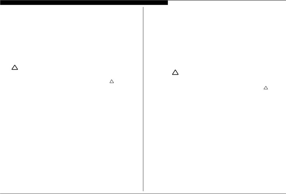
SETTING UP AND CARRYING THE TV
●● Disconnect all cables when carrying the TV.
●● Carry the TV with the adequate number of people; larger size TVs require two or more people. ●● Correct hand placement while carrying the TV is very important for safety and to avoid damage.
USE CAUTION WHEN HANDLING THE LCD PANEL
When repairing the LCD panel, be sure you are grounded by using a wrist band.
When installing the LCD panel on a wall, the LCD panel must be secured using the 4 mounting holes on the rear cover.
1.Do not press on the panel or frame edge to avoid the risk of electric shock.
2.Do not scratch or press on the panel with any sharp objects.
3.Do not leave the module in high temperatures or in areas of high humidity for an extended period of time.
4.Do not expose the LCD panel to direct sunlight.
5.Avoid contact with water. It may cause a short circuit within the module.
6.Disconnect the AC power when replacing the backlight or inverter circuit. (High voltage occurs at the inverter circuit at 650Vrms.)
7.Always clean the LCD panel with a soft cloth material.
8.Use care when handling the wires or connectors of the inverter circuit. Damaging the wires may cause a short.
9.Protect the panel from ESD to avoid damaging the electronic circuit (C-MOS).
10.During the repair, DO NOT leave the Power On for more than 1 hour while the TV is face down on a cloth.
KDL-40BX450/40BX451/46BX450/46BX451 |
iii |

CAUTIONS AND WARNINGS
CLEANING THE LCD PANEL
CAUTION: When cleaning the TV, be sure to unplug the power cord to avoid any chance of electric shock.
Clean the cabinet of the TV with a dry soft cloth.
Wipe the LCD screen gently with a soft cloth.
;; Stubborn stains may be removed with a cloth slightly moistened with a solution of mild soap and warm water. ;; If using a chemically pretreated cloth, please follow the instruction provided on the package.
;; Never use strong solvents such as a thinner, alcohol or benzine for cleaning.
;; Periodic vacuuming of the ventilation openings is recommended to ensure proper ventilation.
;; Do Not use paper towels, any type of abrasive pad, rags, rubber or vinyl materials to clean the screen. Using these materials could easily scratch the screen which may result in permanent damage.
;; Do Not use any cleaning product containing alkaline/acid cleaner, scouring powder, or volatile solvent, such as alcohol, ammonia, benzine, thinner or insecticide. Using any of these harsh cleaners may result in permanent damage to the screen.
;; Do Not spray water or detergent directly onto the TV screen . If liquid drips into the bottom of the screen it may cause a failure.
KDL-40BX450/40BX451/46BX450/46BX451 |
iv |
CAUTIONS AND WARNINGS
SAFETY CHECK-OUT
After correcting the original service problem, perform the following safety checks before releasing the set to the customer:
1.Check the area of your repair for unsoldered or poorly soldered connections. Check the entire board surface for solder splashes and bridges.
2.Check the interboard wiring to ensure that no wires are “pinched” or touching high-wattage resistors.
3.Check that all control knobs, shields, covers, ground straps, and mounting hardware have been replaced. Be absolutely certain that you have replaced all the insulators.
4.Look for unauthorized replacement parts, particularly transistors, that were installed during a previous repair. Point them out to the customer and recommend their replacement.
5.Look for parts which, though functioning, show obvious signs of deterioration. Point them out to the customer and recommend their replacement.
6.Check the line cords for cracks and abrasion. Recommend the replacement of any such line cord to the customer.
7.Check the antenna terminals, metal trim, “metallized” knobs, screws, and all other exposed metal parts for AC leakage. Check leakage as described in “Leakage Test”.
LEAKAGE TEST
The AC leakage from any exposed metal part to earth ground and from all exposed metal parts to any exposed metal part having a return to chassis, must not exceed 0.5 mA (500 microamperes). Leakage current can be measured by any one of three methods.
1.A commercial leakage tester.
Follow the manufacturers’ instructions provided with the tester.
2.A battery-operated AC milliammeter.
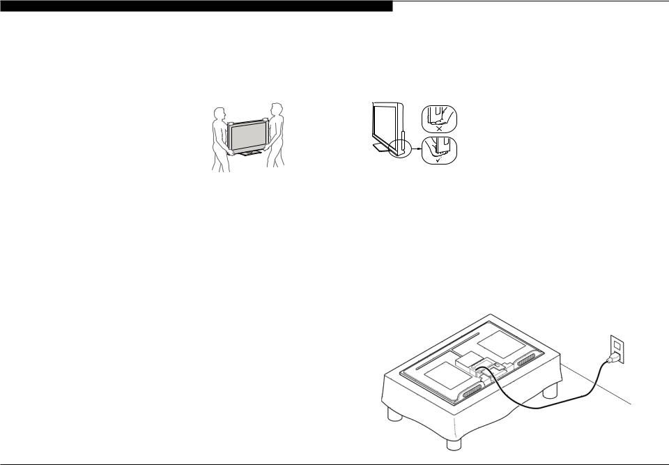
3.Measuring the voltage drop across a resistor by means of a VOM or battery-operated AC voltmeter. The “limit” indication is 0.75 V, so analog meters must have an accurate low voltage scale. Nearly all battery-operated digital multimeters that have a 2 VAC range are suitable. (see Figure A)
To Exposed Metal
Parts on Set
AC
0.15 µF 


 Voltmeter
(0.75V)
Earth Ground
Figure A. Use an AC voltmeter to check AC leakage.
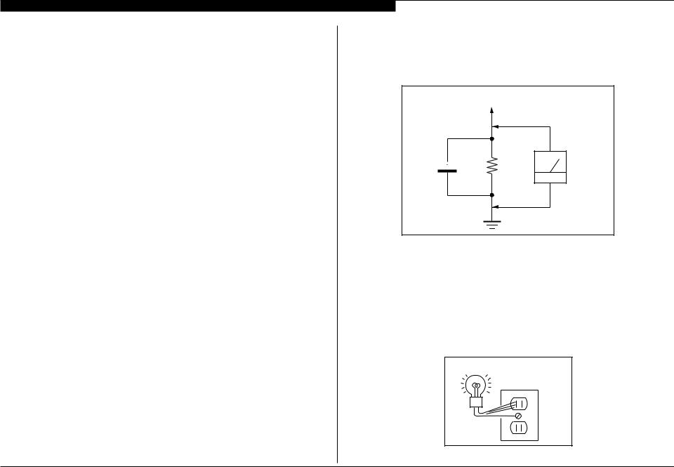
HOW TO FIND A GOOD EARTH GROUND
The cover-plate retaining screw on most AC outlet boxes is at earth ground. Verify the AC outlet box retaining screw ground by connecting a 60W to 100W incandescent (not a neon or fluorescent lamp) between the hot side of the receptacle and the retaining screw. Try both slots, if necessary, to locate the hot side on the line; the lamp should light at normal brilliance if the screw is at ground potential. (see Figure B)
Trouble Light
AC Outlet Box
Figure B. Checking for earth ground.
KDL-40BX450/40BX451/46BX450/46BX451 |
v |
SECTION 1 - FEATURES AND OVERVIEW
FEATURES
The AZ3FK chassis is one of several designs for the 2012 model line of Sony Bravia® LCD televisions. This manual covers the following models:
KDL-40BX450
KDL-40BX451
KDL-46BX450
KDL-46BX451
The BRAVIA® Sync™ BX45x series LED LCD HDTV ●● Brilliant Full HD (1080p) picture quality
●● Four HD inputs for a cable box, PS3™ and more1 ●● Share your pictures on the big screen via USB input ●● Crisp detail & contrast w/ Clear Resolution Enhancer ●● Optimized picture based on what you’re watching
●● Less grain & a clear picture w/ Digital Noise Reduction ●● Theater-like movie viewing with 24p True Cinema
●● One remote for multiple devices with BRAVIA® Sync™2
1.Cables sold separately.
2.Syncs with BRAVIA® Sync or Theatre Sync™ products.
SPECIFICATIONS
System
Television system |
NTSC: American TV standard |
|
ATSC (8VSB terrestrial): ATSC compliant 8VSB |
|
QAM on cable: ANSI/SCTE 07 2000 (Does not include CableCARD functionality) |
|
|
Channel coverage |
Analog terrestrial: 2 - 69 / Digital terrestrial: 2 - 69 |
|
Analog Cable: 1 - 135 / Digital Cable: 1 - 135 |
Panel system |
LCD (Liquid Crystal Display) Panel |
|
|
Speaker output |
KDL-46/40BX450: 6 W + 6 W |
|
KDL-46/40BX451: 8 W + 8 W |
Input/Output jacks |
|
CABLE/ANTENNA |
75-ohm external terminal for RF inputs |
|
|
VIDEO IN 1 |
VIDEO: 1 Vp-p, 75 ohms unbalanced, sync negative |
|
AUDIO: 500 mVrms (Typical) / Impedance: 47 kilohms |
COMPONENT IN |
YPBPR (Component Video): Y: 1.0 Vp-p, 75 ohms unbalanced, |
|
sync negative / PB:0.7 Vp-p, 75 ohms |
|
PR : 0.7 Vp-p, 75 ohms / Signal format: 480i, 480p, 720p, 1080i, 1080p |
|
AUDIO: 500 mVrms (Typical) / Impedance: 47 kilohms |
|
|
HDMI IN 1/2 |
HDMI: Video: 480i, 480p, 720p, 1080i, 1080p, 1080/24p |
|
Audio: Two channel linear PCM 32, 44.1 |
|
and 48 kHz, 16, 20 and 24bits, Dolby Digital |
|
PC Input (see Operating Instructions) |
|
|
AUDIO OUT |
500 mVrms (typical) |
|
|
DIGITAL AUDIO OUT |
PCM/Dolby Digital optical signal |
(OPTICAL) |
|
PC IN |
D-s ub 15-pin, analog R G B , 0.7 Vp-p, 75 ohms, positive |
|
See the PC Input Signal Reference Chart for PC and HDMI IN on page 50. |
|
|
PC/HDMI IN 1 AUDIO IN |
Stereo mini jack, 500 mVrms, (Typical) / Impedance: 47 kilohms |
|
|
US B |
K DL-46/40B X450: Photo, Music and Video |
|
KDL-46/40BX451: Photo and Video |
|
|
KDL-40BX450/40BX451/46BX450/46BX451 |
1 |

SECTION 1 - FEATURES AND OVERVIEW
Model name |
|
KDL-46BX450 |
|
KDL-40BX450 |
||
|
|
|
|
KDL-46BX451 |
|
KDL-40BX451 |
Power and others |
|
|
|
|
||
Power requirement |
|
110-240 V AC, 50/60 Hz (U.S.A./Canada/Mexico 120 V AC, 60 Hz) |
||||
|
|
|
|
|
|
|
Power consumption |
|
188 W |
|
158 W |
||
|
in use |
|
|
|
||
|
|
|
|
|
|
|
|
in standby |
|
Less than 0.2 W with 120 V AC and with 240 V AC less than 0.3 W |
|||
|
|
|
|
|
|
|
Screen size* |
|
|
46 |
|
40 |
|
(inches measured diagonally) |
|
|||||
|
|
|
||||
Display resolution |
|
1,920 dots (horizontal) × 1,080 lines (vertical) |
||||
|
|
|
|
|||
Speaker/Full range (2) |
(mm) |
40 × 100 |
|
|||
|
|
|
(inches) |
(1 5/8 × 4) |
|
|
Dimensions* with stand |
(mm) |
1,112 × 713 × 279 |
|
980 × 639 × 231 |
||
|
|
|
(inches) |
43 7/8 × 28 1/8 × 11 |
|
38 5/8 × 25 1/4 × 9 1/8 |
|
|
without stand (mm) |
1,112 × 675 × 97 |
|
980 × 601 × 94 |
|
|
|
|
(inches) |
43 7/8 × 26 5/8 × 3 7/8 |
|
38 5/8 × 23 3/4 × 3 3/4 |
|
wall-mount hole pattern |
300 × 300 |
|
|||
|
(mm) |
|
|
|
||
|
|
|
|
|
|
|
|
wall-mount screw size |
M6 (length: 8-12mm) |
|
|||
|
(mm) |
|
|
|
||
|
|
|
|
|
|
|
|
|
|
|
|
|
|
Mass* |
with stand (kg) |
17.2 |
|
13.8 |
||
|
|
|
(lb.) |
37.9 |
|
30.4 |
|
|
without stand (kg) |
16.0 |
|
12.8 |
|
|
|
|
(lb.) |
35.3 |
|
28.2 |
|
|
|
|
|
||
Supplied accessories |
|
Remote control RM-YD080 (1)/Size AA batteries (2)/Operating Instructions (1)/Quick Setup |
||||
|
common to all models |
Guide (1)/Warranty Card (1)/Safety and Regulatory Booklet (1)/Software License (1)/Stand |
||||
|
installation guide (1)/Table-Top Stand (1 set)/Screw (3) |
|
||||
|
|
|
|
|
||
|
|
|
|
|
||
Optional accessories |
|
Connecting cables / Support Belt Kit / Wall-Mount Bracket: SU-WL500 |
||||
|
|
|
|
|
|
|
•Optional accessories availability depends on its stock.
•Design and speci cations are subject to change without notice. * Dimensions and mass are approximate values.
KDL-40BX450/40BX451/46BX450/46BX451 |
2 |
SECTION 1 - FEATURES AND OVERVIEW
CHASSIS OVERVIEW
The primary circuits in the AZ3FK chassis consist of a Main Board (A Board), Power Supply Board (G10 Board for the 40” models, and G11 Board for the 46” models), the IR Board (H Board), the Switch Unit, and the LCD Panel Assembly which includes the TCON Board and the Inverter MT Board.
NOTE: For connector part number information, refer to “Connectors” on page 19. For Wire Dressing information, refer to “Wire Dressing” on page 21.
INV
G10/G11
A
SWITCH
UNIT
H
BOARD LAYOUT
KDL-40BX450/40BX451/46BX450/46BX451 |
3 |

SECTION 1 - FEATURES AND OVERVIEW
OVERALL CIRCUIT DESCRIPTION
“Block Diagram” on page 9 provides an overview of the AZ3FK chassis. The following are descriptions of the boards and their functions.
MAIN BOARD
Common to all models utilizing theAZ3FK chassis, the Main Board contains most of the video processing circuitry along with all audio processing. Control of the television is accomplished via a CPU embedded within the MT5389 processor. Below is a list of the key components located on the Main Board.
TUNER
The tuner is a combination ATSC/NTSC unit. It can receive traditional analog NTSC signals via cable or terrestrial along with ATSC digital signals via terrestrial (8VSB) or cable (64 or 256 QAM).
MT5389 PROCESSOR
This IC performs the majority of the necessary audio and video processing on the Main Board.
Analog Video Input Switch: All analog video sources are selected and A/D converted and scaled (if necessary) to 1920 X 1080p 60HZ resolution.
Digital Audio and Video Decoder: The MPEG2 and Digital Dolby audio streams are received from the tuner for decompression. All video sources which are not native 1920 X 1080p 60HZ are scaled to this resolution. Digital audio content is output to the class D amplifier for processing and amplification.
Audio Processing: Analog audio sources are selected and A/D converted directly by the MT5389. The audio information is then processed digitally. Digital audio from the tuner and HDMI sources is also input and processed. Class D amplifier provides the drive for the speakers.
HDMI Input and Switching: The customer can select the HDMI1 through HDMI4 input. Each HDMI input contains a dedicated EDI NVM (not shown) to provide display information data to any device connected via the HDMI inputs.
CPU: The CPU internal to the MT5389 processor controls all aspects of the television functions. Input from the user along with monitoring of critical circuits is also performed by this CPU.
LVDS Transmitter: Integrated into the MT5389 is a Low Voltage Differential Signaling (LVDS) transmitter. This circuit converts the 8-bit parallel RGB video information into a set of high speed serial lines for noise-free transmission to the TCON circuits located internally to the LCD panel.
POWER SUPPLY BOARD
There are 2 different Power Supply boards used in the models in this manual. The type of board depends on the size of LCD panel. They are:
●● G10 for the 40” models ●● G11 for the 46’ models
There are 2 distinct sections on the power supply:
Standby Supply: Continuously operational as long asAC power is applied, the standby supply generates 3.3VDC for the circuits requiring power while the unit is turned off. An unregulated 15-volt line is present to provide power to the main relay, PFC and main power supply at turn-on.
Main Supply: Once the power supply receives a power-on command from the CPU on the A board, the main switching supply is turned on to provide a regulated 12V source, a dedicated un-regulated 15V for the audio circuits and an unregulated 24V source for the inverter circuit.
IR BOARD
Designated as the H Board, the IR Board contains the power, standby, and timer LED’s that is located on this board along with the IR remote receiver and light level sensor.
SWITCH UNIT
This board contains the power, channel and volume up/down, and menu buttons.
KDL-40BX450/40BX451/46BX450/46BX451 |
4 |
Loading...