


HCD-CPX11
Table of contents
 Loading...
HCD-CPX11
Tape deck section
Recording system 4-track 2-channel stereo
Frequency response 50 – 13,000 Hz (±3 dB),
using Sony TYPE I
cassettes
Tuner section
FM stereo, FM/AM superheterodyne tuner
FM tuner section
Tuning range 87.5 – 108.0 MHz (50 kHz
step)
Antenna FM wire antenna
Antenna terminals 75 ohms unbalanced
Intermediate frequency 10.7 MHz
AM tuner section
Tuning range
European model: 531 – 1,602 kHz
(with the tuning interval
set at 9 kHz)
European model:
DIN power output (rated): 55 + 55 W
(4 ohms at 1 kHz, DIN)
Continuous RMS power output (reference):
75 + 75 W
(4 ohms at 1 kHz, 10%
THD)
Other models:
The following measured at 220 – 240 V AC, 50/60 Hz
DIN power output (rated): 55 + 55 W
(4 ohms at 1 kHz, DIN)
Continuous RMS power output (reference):
75 + 75 W
(4 ohms at 1 kHz, 10%
THD)
Inputs
MD/VIDEO IN (phono jacks):
Sensitivity 450/250 mV,
impedance 47 kilohms
Outputs
CD DIGITAL OUT: Optical Wavelength:
660 nm
PHONES: accepts headphones with
an impedance of 8 ohms or
more
SPEAKER: accepts impedance of 4 ohms
CD pAmplifier section layer section
Laser Semiconductor laser
(CD: λ=780 nm)
Emission duration:
continuous
Frequency response CD: 2 Hz – 20 kHz
Wavelength 780 – 790 nm
Other models: 530 – 1,710 kHz
(with the tuning interval
set at 10 kHz)
531 – 1,602 kHz
(with the tuning interval
set at 9 kHz)
Antenna AM loop antenna, external
antenna terminal
Intermediate frequency 450 kHz
General
Power requirements
European model: 230 V AC, 50/60 Hz
Korean model: 220 V AC, 60 Hz
Australian model: 230 – 240 V AC, 50/60 Hz
Power consumption
European model: 50 W
0.3 W (in Power Saving
mode)
Korean model: 50 W
Other models: 50 W
Dimensions (w/h/d) incl. projecting parts and controls
Approx. 175 × 240.5 × 291
mm
Mass Approx. 4.3 kg
Design and specifications are subject to change
without notice.
SERVICE MANUAL
Ver 1.0 2004.04
HCD-CPX11 is the Amplifier, CD play er,
Tape Deck and Tuner section in CMTCPX11.
CD
Section
Tape deck Model Name Using Similar Mechanism NEW
Section Tape Transport Mechanism Name CMAL1Z-236A
AEP Model
UK Model
Korean Model
Australian Model
Model Name Using Similar Mechanism NEW
CD Mechanism Type CDM80BH-F1BD81
Optical Pick-up Name KSM-215DCP
9-877-766-01
2004D1678-1
© 2004.04
Sony Corporation
Home Audio Company
Published by Sony Engineering Corporation
SPECIFICATIONS
MICRO HI-FI COMPONENT SYSTEM
HCD-CPX11
Notes on chip component replacement
• Never reuse a disconnected chip component.
• Notice that the minus side of a tantalum capacitor may be
damaged by heat.
Flexible Circuit Board Repairing
• Keep the temperature of the soldering iron around 270 °C
during repairing.
• Do not touch the soldering iron on the same conductor of the
circuit board (within 3 times).
• Be careful not to apply force on the conductor when soldering
or unsoldering.
CAUTION
Use of controls or adjustments or performance of procedures
other than those specified herein may result in hazardous radiation
exposure.
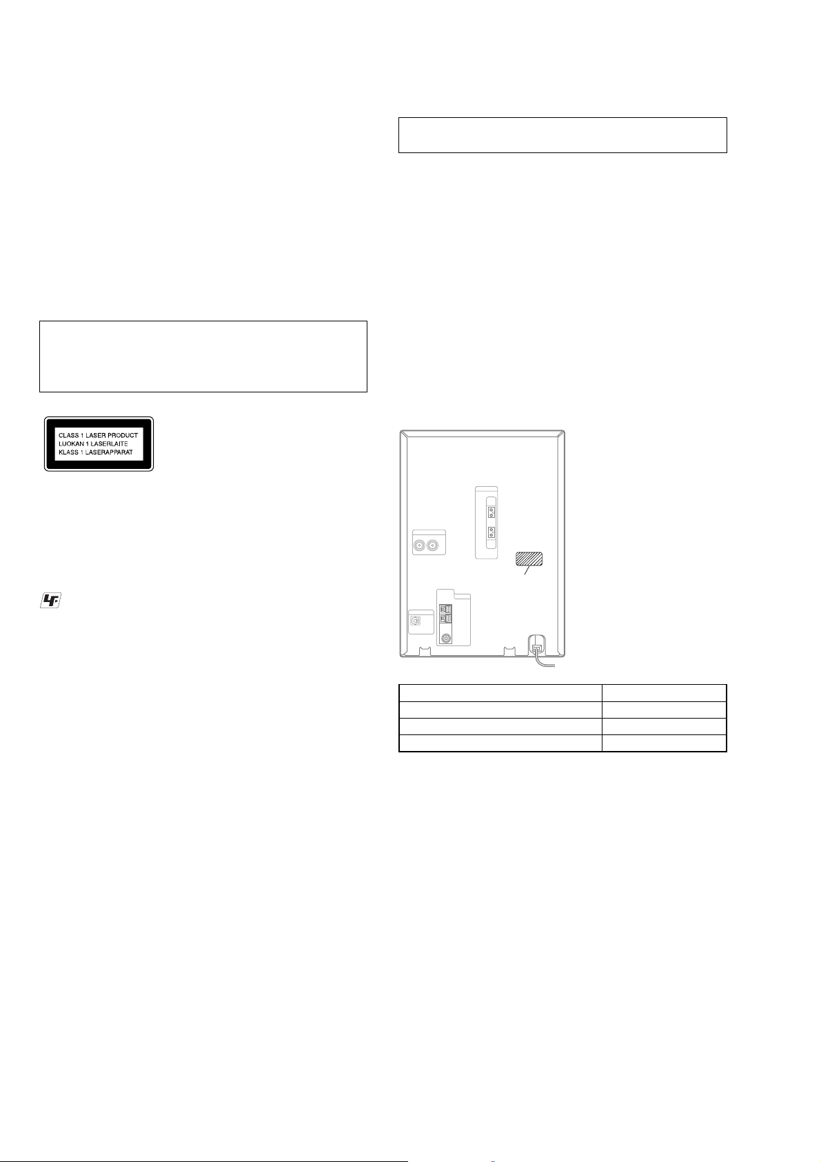
This appliance is
classified as a CLASS 1
LASER product. This
label is located on the
rear exterior.
UNLEADED SOLDER
Boards requiring use of unleaded solder are printed with the leadfree mark (LF) indicating the solder contains no lead.
(Caution: Some printed circuit boards may not come printed with
the lead free mark due to their particular size)
NOTES ON HANDLING THE OPTICAL PICK-UP
BLOCK OR BASE UNIT
The laser diode in the optical pick-up block may suffer electrostatic
break-down because of the potential difference generated by the
charged electrostatic load, etc. on clothing and the human body.
During repair, pay attention to electrostatic break-down and also
use the procedure in the printed matter which is included in the
repair parts.
The flexible board is easily damaged and should be handled with
care.
NOTES ON LASER DIODE EMISSION CHECK
The laser beam on this model is concentrated so as to be focused on
the disc reflective surface by the objective lens in the optical pickup block. Therefore, when checking the laser diode emission,
observe from more than 30 cm away from the objective lens.
MODEL IDENTIFICATION
– Back Panel –
Part No.
: LEAD FREE MARK
Unleaded solder has the following characteristics.
• Unleaded solder melts at a temperature about 40 °C higher
than ordinary solder.
Ordinary soldering irons can be used but the iron tip has to be
applied to the solder joint for a slightly longer time.
Soldering irons using a temperature regulator should be set to
about 350 °C.
Caution: The printed pattern (copper foil) may peel away if
the heated tip is applied for too long, so be careful!
• Strong viscosity
Unleaded solder is more viscou-s (sticky, less prone to flow)
than ordinary solder so use caution not to let solder bridges
occur such as on IC pins, etc.
• Usable with ordinary solder
It is best to use only unleaded solder but unleaded solder may
also be added to ordinary solder.
SAFETY-RELATED COMPONENT WARNING!!
Model Name Part No.
AEP and UK models 4-252-358-0[]
Korean model 4-252-358-2[]
Australian model 4-252-358-3[]
COMPONENTS IDENTIFIED BY MARK 0 OR DOTTED LINE
WITH MARK 0 ON THE SCHEMATIC DIAGRAMS AND IN
THE PARTS LIST ARE CRITICAL TO SAFE OPERATION.
REPLACE THESE COMPONENTS WITH SONY PARTS WHOSE
PART NUMBERS APPEAR AS SHOWN IN THIS MANUAL OR
IN SUPPLEMENTS PUBLISHED BY SONY.
2

TABLE OF CONTENTS
HCD-CPX11
1. SERVICING NOTES ................................................ 4
2. GENERAL ................................................................... 9
3. DISASSEMBLY
3-1. Cover ............................................................................... 12
3-2. Front Panel Section ......................................................... 12
3-3. TC Board, Mechanical Deck .......................................... 13
3-4. PANEL Board .................................................................. 13
3-5. MAIN Board, PRE AMP Board...................................... 14
3-6. CD Mechanism Deck (CDM80BH-F1BD81) ................. 14
3-7. Chassis (Top) ................................................................... 15
3-8. Lever (Loading R/L)........................................................ 16
3-9. Disc Stop Lever, Disc Sensor Lever ................................ 17
3-10. DRIVER Board ............................................................... 17
3-11. BD81A Board .................................................................. 18
3-12. BU Section ...................................................................... 18
3-13. Optical Pick-up (KSM-215DCP) .................................... 19
3-14. Lever (BU Lock) ............................................................. 19
3-15. Close Lever...................................................................... 20
3-16. Dir Lever, Gear (IDL-B).................................................. 20
3-17. Gear (IDL-C) ................................................................... 21
4. TEST MODE ............................................................... 22
5. ELECTRICAL ADJUSTMENTS
Deck Section.................................................................... 24
CD Section ...................................................................... 25
6. DIAGRAMS
6-1. Block Diagram – BD/DRIVER Section – ...................... 28
– TUNER/TAPE DECK Section – .................................. 29
– MAIN Section – ........................................................... 30
– DISPLAY/POWER SUPPLY Section – ....................... 31
6-2. Printed Wiring Board – BD81A Section – ..................... 32
6-3. Schematic Diagram – BD81A Section – ........................ 33
6-4. Printed Wiring Board – TC Section –............................. 34
6-5. Schematic Diagram – TC Section – ............................... 35
6-6. Printed Wiring Board – MAIN Section – ....................... 36
6-7. Schematic Diagram – MAIN Section –.......................... 37
6-8. Printed Wiring Board – PRE AMP Section – .................. 38
6-9. Schematic Diagram – PRE AMP Section –.................... 39
6-10. Printed Wiring Board – LCD/DRIVER Section –........... 40
6-11. Schematic Diagram – LCD/DRIVER Section – ............. 41
6-12. Printed Wiring Board – PANEL Section – ..................... 42
6-13. Schematic Diagram – PANEL Section –........................ 43
6-14. Printed Wiring Board – S-MASTER Section –.............. 44
6-15. Schematic Diagram – S-MASTER Section –................. 45
6-16. IC Pin Function Description ............................................ 51
7. EXPLODED VIEWS
7-1. MAIN Section ................................................................. 57
7-2. Front Panel Section ......................................................... 58
7-3. Lid (TC) Section.............................................................. 59
7-4. Chassis Section................................................................ 60
7-5. S-MASTER AMP Section ............................................... 61
7-6. CD Mechanism Deck Section-1
(CDM80BH-F1BD81)..................................................... 62
7-7. CD Mechanism Deck Section-2
(CDM80BH-F1BD81)..................................................... 63
7-8. CD Mechanism Deck Section-3
(CDM80BH-F1BD81)..................................................... 64
7-9. Base Unit Section (BU-F1BD81A)................................. 65
8. ELECTRICAL PARTS LIST .................................. 66
3
HCD-CPX11
SECTION 1
SERVICING NOTES
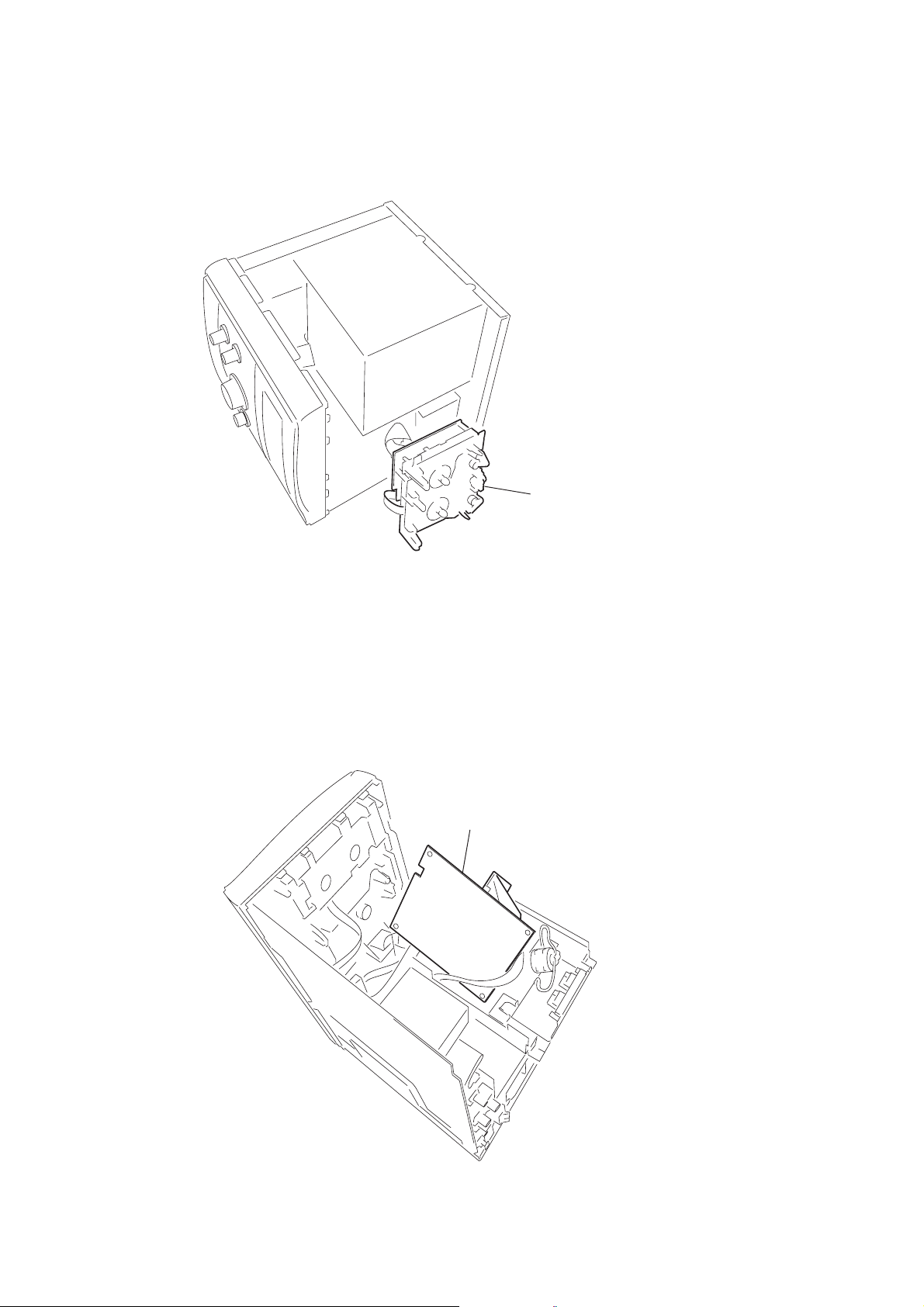
SERVICE POSITION OF THE TAPE MECHANISM DECK
SERVICE POSITION OF THE S-MASTER AMP BOARD
• Remove the switching regulator, the S-MASTER AMP board block first,
then remove the S-MASTER AMP board from the S-MASTER AMP board block.
S-MASTER AMP board
tape mechanism deck
4
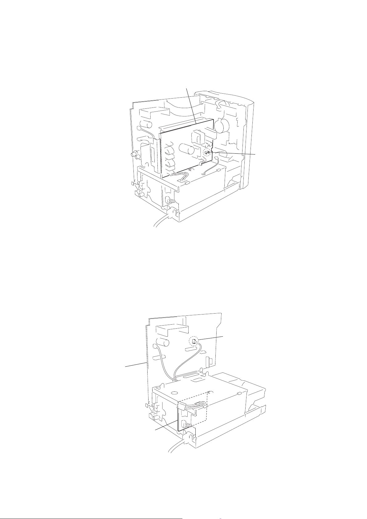
JUDGING WHETHER THE SWITCHING REGULATOR IS GOOD OR DEFECTIVE
•
The switching regulator is judged to be good when the terminal voltage at the switching regulator CN4 is 12 V.
switching regulator
CN4
HCD-CPX11
JUDGING WHETHER THE SUB POWER BOARD IS GOOD OR DEFECTIVE
• It is judged to be good when the voltage between pin 2 (+4 V) and pin 3 (GND) of the MAIN board CN302 is 4 V.
CN302
MAIN board
SUB POWER board
5
HCD-CPX11
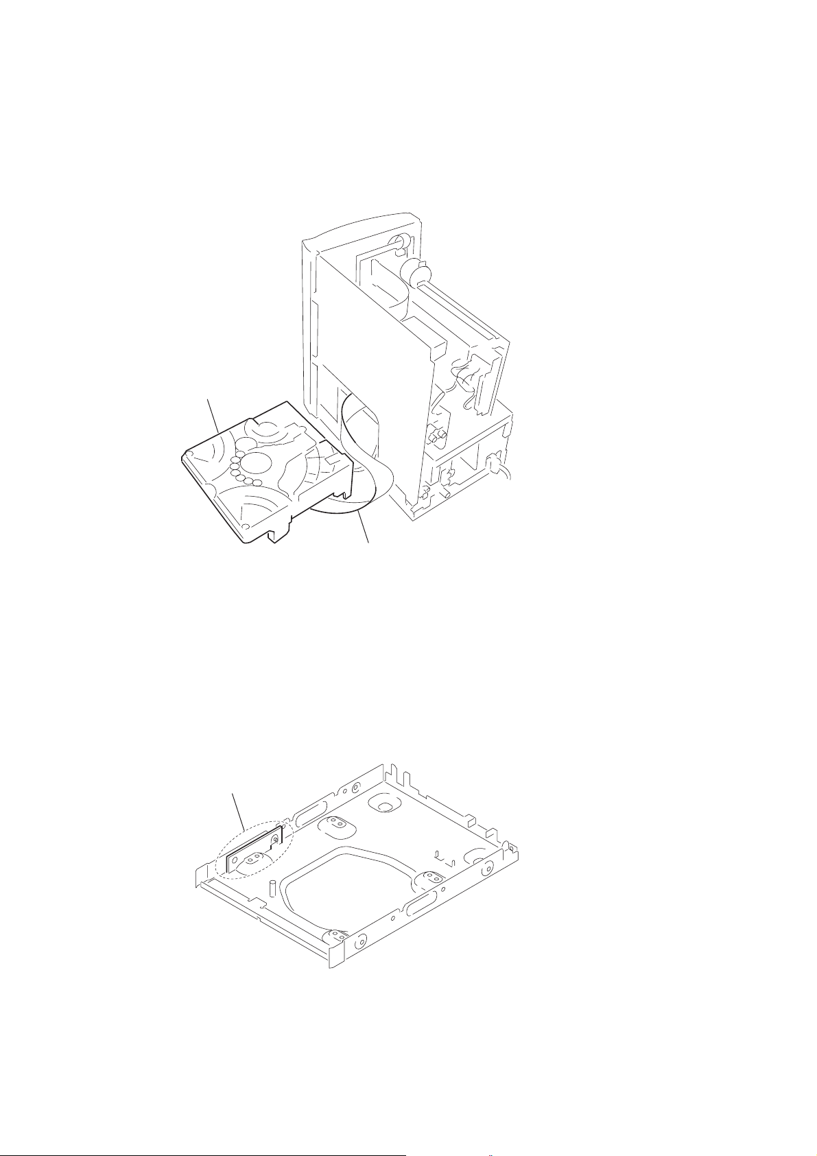
SERVICE POSITION OF THE CD MECHANISM DECK
• Remove the front panel and the circuit boards once in order to remove the CD mechanism deck.
After removing the CDM, reassemble the panel and the circuit boards back to the original state.
CD mechanism deck
COVER BOARD
• This is the board used to blind the slot. Do not remove.
cover board
Extension cable should be used.
(J-2501-248-A)(1.00mm/27P/300L)
6
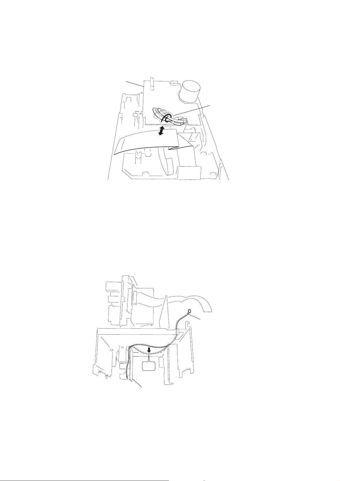
FIXING THE TC CABLES
e
• To prevent cables from noise, fix the cables with the lead pin so that the cables do not contact with the flexible board.
TC board
lead pin
HCD-CPX11
PREVENTING THE SUB POWER CABLES FROM SAGGING DOWN
• Be careful not to contact with the CD mechanism deck.
SUB POWER cabl
NG
SUB POWER board
7
HCD-CPX11
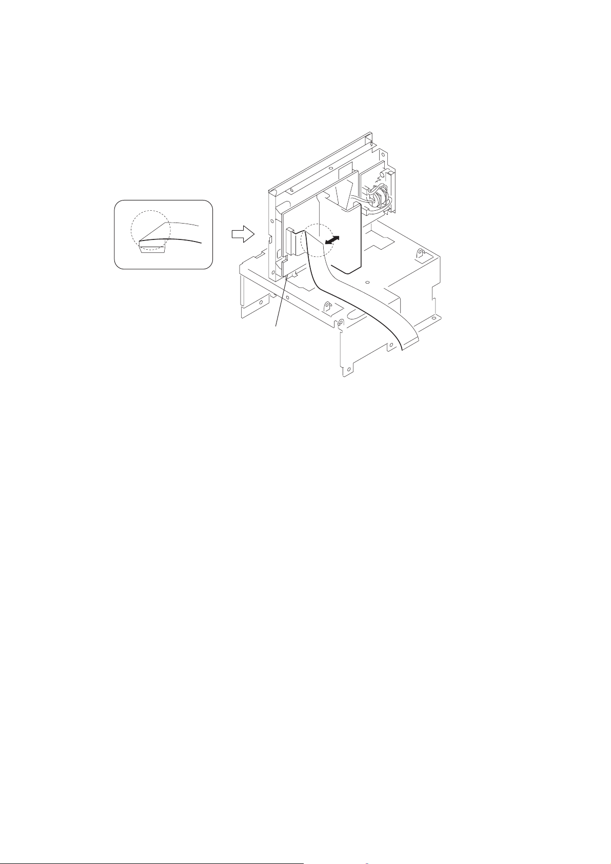
CAUTION SO THAT THE FLEXIBLE BOARD SHOULD NOT CONTACT WITH THE HEAT SINK
• When the flexible board is replaced, give the folding at the same position of the new flexible board with that of the old flexible board.
S-MASTER AMP board
8
SECTION 2
Illustrati
GENERAL
List of button locations and reference pages
HCD-CPX11
This section is extracted
from instruction manual.
How to use this page
Use this page to find the location of buttons and other
parts of the system that are mentioned in the text.
Main unit
ALPHABETICAL ORDER
A – O
BASS +/– wa (16)
CD SYNCHRO qa (15)
DIRECTION wd (14, 15, 16, 18)
Disc slot ql (8)
DISPLAY wf (13, 20)
Display window 3
DSGX w; (16)
FM MODE qs (12, 25)
FUNCTION 0 (8, 10, 12, 14, 16,
23, 26)
1
2
P – Z
PHONES jack qk
PLAY MODE wd (8, 10, 15, 25,
26)
Remote sensor 2
REPEAT qs (9)
TREBLE +/– ws (16)
TUNER/BAND 9 (11, 12)
TUNING MODE wd (11, 12)
TUNING +/– qd (11, 12)
VOLUME qf (17)
3
on number
r
DISPLAY
Name of button/part Reference page
4
wf (13, 20)
RR
BUTTON DESCRIPTIONS
?/1 (power) 1 (7, 12, 17, 18,
26)
TAPE Z (eject) 4 (14)
TAPE nN (play) 5 (14, 15,
16, 18)
TAPE x (stop) 6 (14, 15, 16,
26)
TAPE X (pause) 7 (14, 15, 16)
TAPE z REC (record) 8 (16)
lm/ML (rewind/fast
forward, go back/go forward)
qd (9, 10, 14)
CD NX (play pause) qh (8, 9,
10)
CD x (stop) qj (9, 12, 26)
CD Z (eject) qg (9)
wf
wd
ws
wa
w;
ql
qk
5
6
7
8
9
0
qa
qs
qd
qf
qg
qh
qj
9
HCD-CPX11
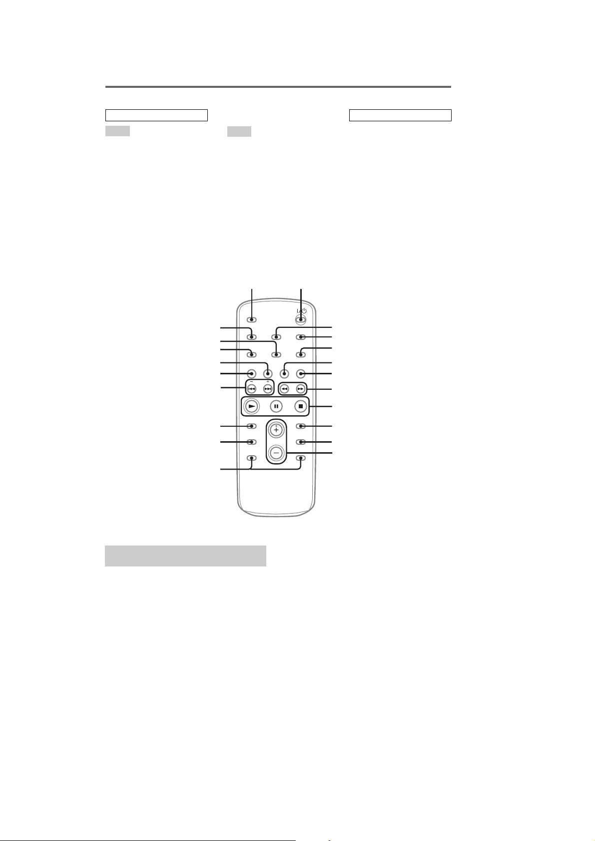
Remote control
ALPHABETICAL ORDER
A – O
ALBUM +/– qa (9, 10, 15)
CD qh (8, 10)
CLEAR qd (10)
CLOCK/TIMER SELECT 2
(18, 19, 24)
CLOCK/TIMER SET 3 (7, 17,
18)
DISPLAY ql (13, 20)
ENTER 9 (7, 10, 11, 17, 18, 19)
EQ qs (16)
FM MODE 4 (12, 25)
FUNCTION 6 (8, 10, 12, 14, 16,
23, 26)
P – Z
PLAY MODE qk (8, 10, 15, 25)
REPEAT 4 (9)
SLEEP w; (17)
TAPE qg (14)
TUNER/BAND 5 (11, 12)
TUNER MEMORY qj (11)
TUNING MODE qk (11, 12)
VOLUME +/– 0 (17)
w; 1
ql
qk
qj
qh
qg
qf
BUTTON DESCRIPTIONS
?/1 (power) 1 (7, 12, 17, 18)
x (stop) 8 (9, 14)
X (pause) 8 (9, 14)
N (play) 8 (8, 10, 14, 18)
./> (skip back/skip
forward) qf (7, 9, 10, 16, 17,
18, 19)
m/M (rewind/fast forward)
7 (9, 14)
+/– (tuning) qf (11, 12)
2
3
4
5
6
7
10
qd
qs
qa
*Button does not function with this model.
Setting the clock
Use buttons on the remote for the operation.
1
Press ?/1 to turn on the system.
2
Press CLOCK/TIMER SET.
3
Press
./>
hour.
4
Press ENTER.
5
Press
./>
minute.
6
Press ENTER.
The clock starts working.
To adjust the clock
1
Press CLOCK/TIMER SET.
2
Press
./>
appears, then press ENTER.
3
Do the same procedures as step 3 to 6
above.
Note
The clock is not displayed in Power Saving Mode.
repeatedly to set the
repeatedly to set the
until “CLOCK SET”
8
9
*
0
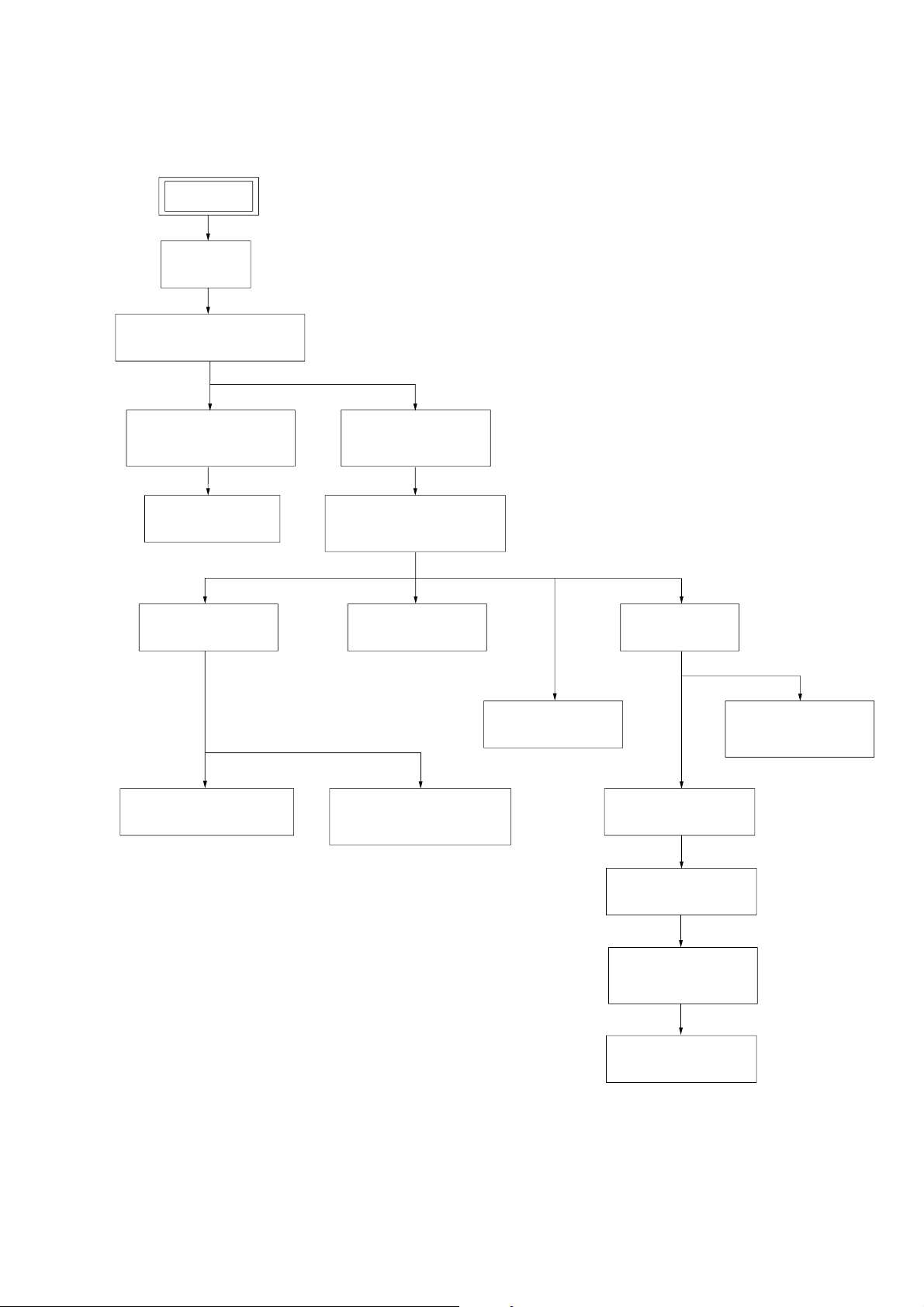
•This set can be disassembled in the order shown below.
3-5.MAIN BOARD,
PRE AMP BOARD
(Page 14)
3-6.CD MECHANISM DECK
(CDM80BH-F1BD81)
(Page 14)
3-3.TC BOARD,
MECHANICAL DECK
(Page 13)
3-7.CHASSIS (TOP)
(Page 15)
3-1.COVER
(Page 12)
3-2.FRONT PANEL SECTION
(Page 12)
3-4.PANEL BOARD
(Page 13)
3-10.DRIVER BOARD
(Page 17)
3-12.BU SECTION
(Page 18)
3-14.LEVER (BU LOCK)
(Page 19)
3-15.CLOSE LEVER
(Page 20)
3-16.DIR LEVER,
GEAR (IDL-B)
(Page 20)
3-17.GEAR (IDL-C)
(Page 21)
3-11.BD81A BOARD
(Page 18)
3-8.LEVER (LOADING R/L)
(Page 16)
3-9.DISC STOP LEVER,
DISC SENSOR LEVER
(Page 17)
3-13.OPTICAL PICK-UP
(KSM-215DCP)
(Page 19)
SET
HCD-CPX11
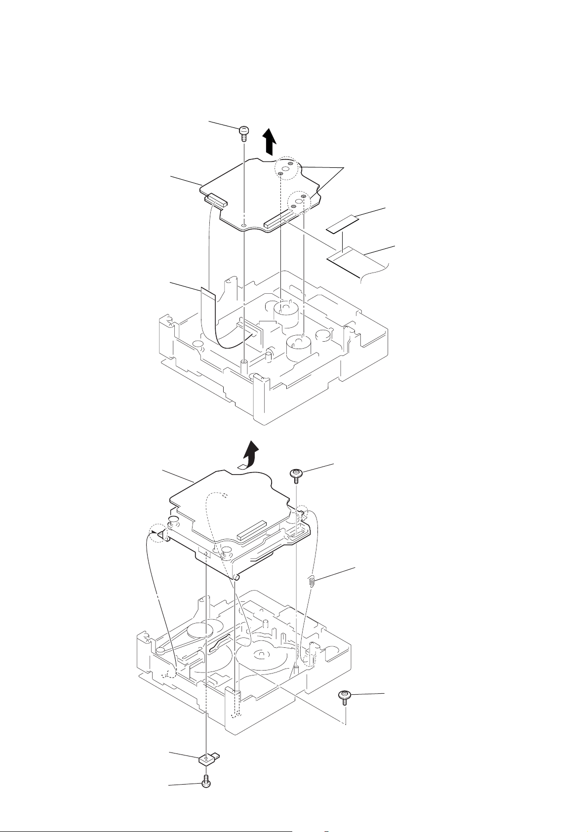
SECTION 3
DISASSEMBLY
11
HCD-CPX11
)
Note: Follow the disassembly procedure in the numerical order given.
3-1. COVER
5
cover
4
2
two case screws
4
3
three screws
(+BVTP 3
1
two case screws
×
6
3-2. FRONT PANEL SECTION
4
wire (flat type) 19 core (CN303)
8
front panel section
2
wire (flat type) 19 core (CN603)
3
connector 4p (CN102)
1
screw (+BVTP 3
× 6
)
12
6
screw (+BVTP 3
× 6
5
wire (flat type) 9 core (CN304)
)
7
three
screws (+BVTP 3
× 6
)
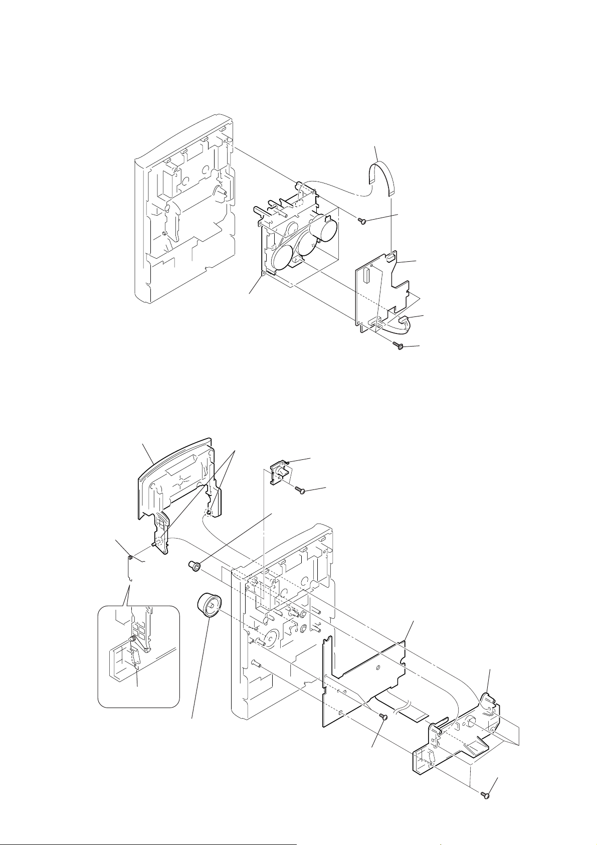
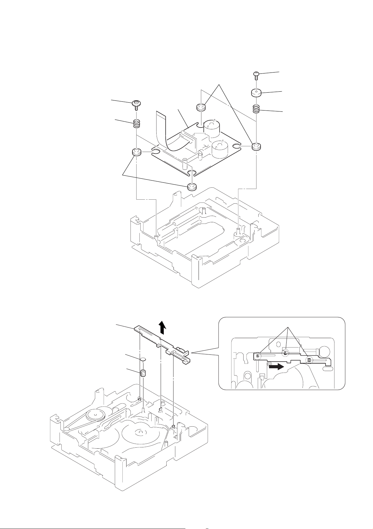
3-3. TC BOARD, MECHANICAL DECK
)
6
five
screws
(+BVTP 2.6
× 8
)
7
holder
qa
PANEL board
q;
two
screws (+BVTP 2.6
× 8
)
8
two
screws (+BVTP 2.6
× 10
)
9
cover
(eject)
5
lid (TC) section
4
two dowels
3
spring (LID TC)
tortion
spring (LID TC)
torsion
1
volume knob
2
two buss knobs
6
mechanical deck
2
wire (flat type) 8 core
1
four
5
4
screws (+BVTP 3
TC board
connector (6p)
HCD-CPX11
× 8
3-4. PANEL BOARD
3
three
(PTPWH2)
screws
13
HCD-CPX11
e
3-5. MAIN BOARD, PRE AMP BOARD
6
connector 2p (CN301)
7
wire (flat type) 15 core (CN307)
8
wire (flat type) 22 core (CN309)
3
back panel
2
qd
two
two
screws (+BVTP 3
1
five
screws (+BVTP 3
5
wire (flat type) 19 cor
screws (+BVTP 3
× 6
× 6
)
× 6
)
)
q;
wire (flat type) 27 core (CN201)
qa
connector 3p (CN302)
9
qf
connector 7p (CN202)
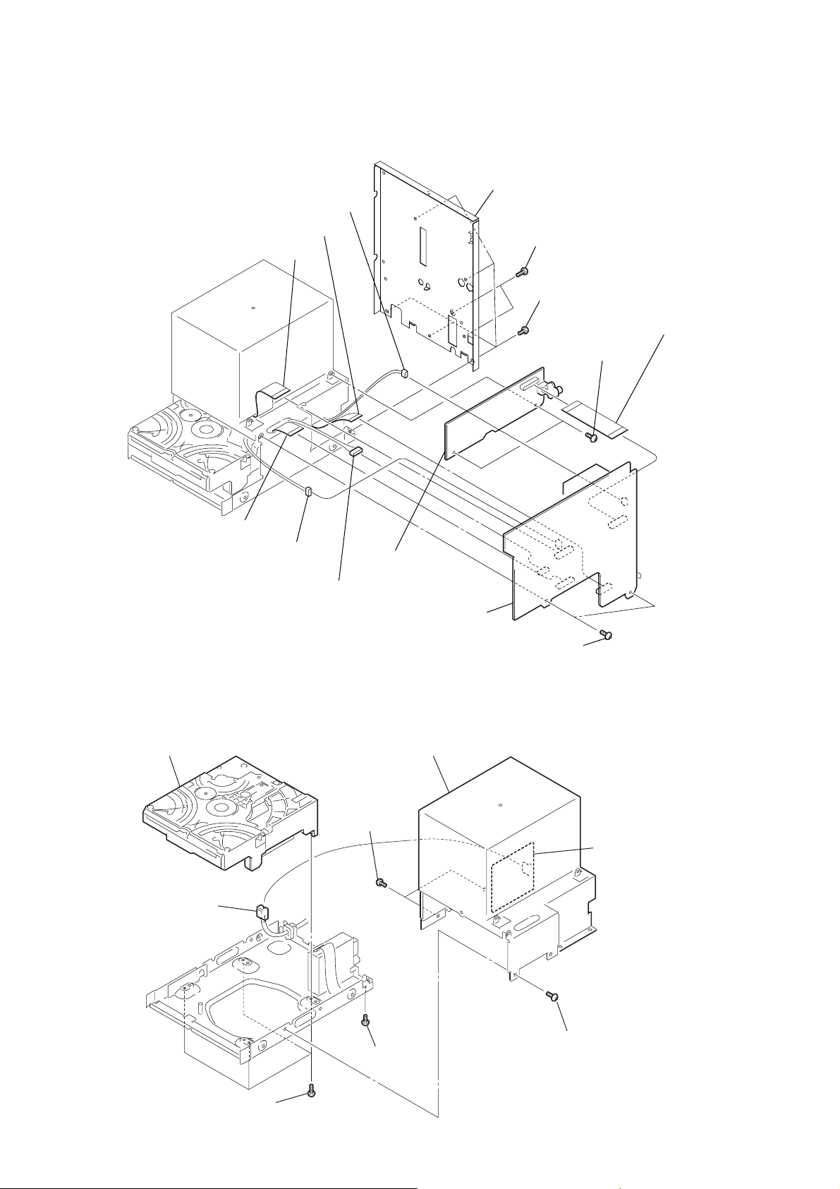
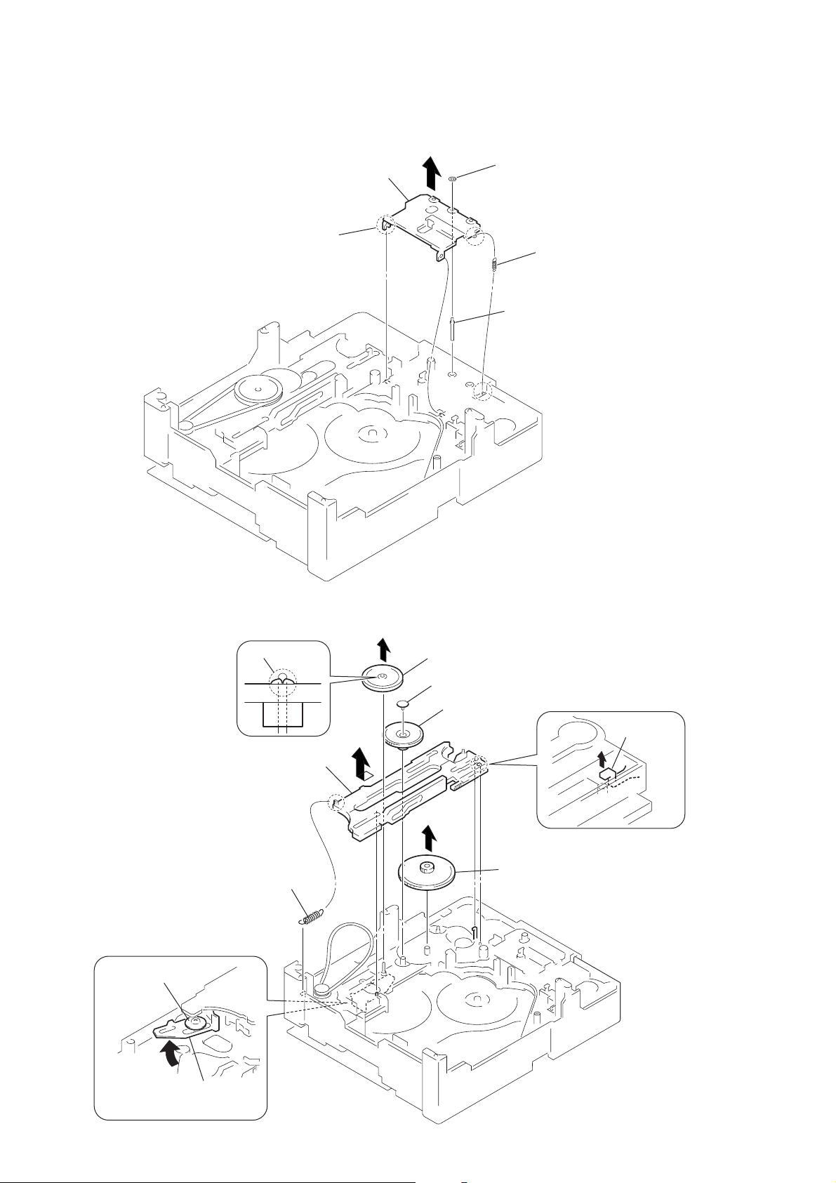
3-6. CD MECHANISM DECK (CDM80BH-F1BD81)
7
CD mechanism deck
2
two
(+BVTP 3
1
connector 2p (CN990)
PRE AMP board
qs
MAIN board
4
two
5
S-MASTER AMP section
screws
× 6
)
screws (+BVTP 3
× 6
)
SUB POWER board
14
6
four
screws (+BVTP 3
× 10
3
4
screw
(+BVTP 3
)
× 6
)
screw (+BVTP 3
× 6
)
3-7. CHASSIS (TOP)
)
4
5
chassis (top)
3
three screws
(+BVTP 2.6 × 8)
two screws
(+P 2 × 10)
1
screw
(+BVTP 2.6
2
lever (CL UP2
HCD-CPX11
×
8)
15
HCD-CPX11
)
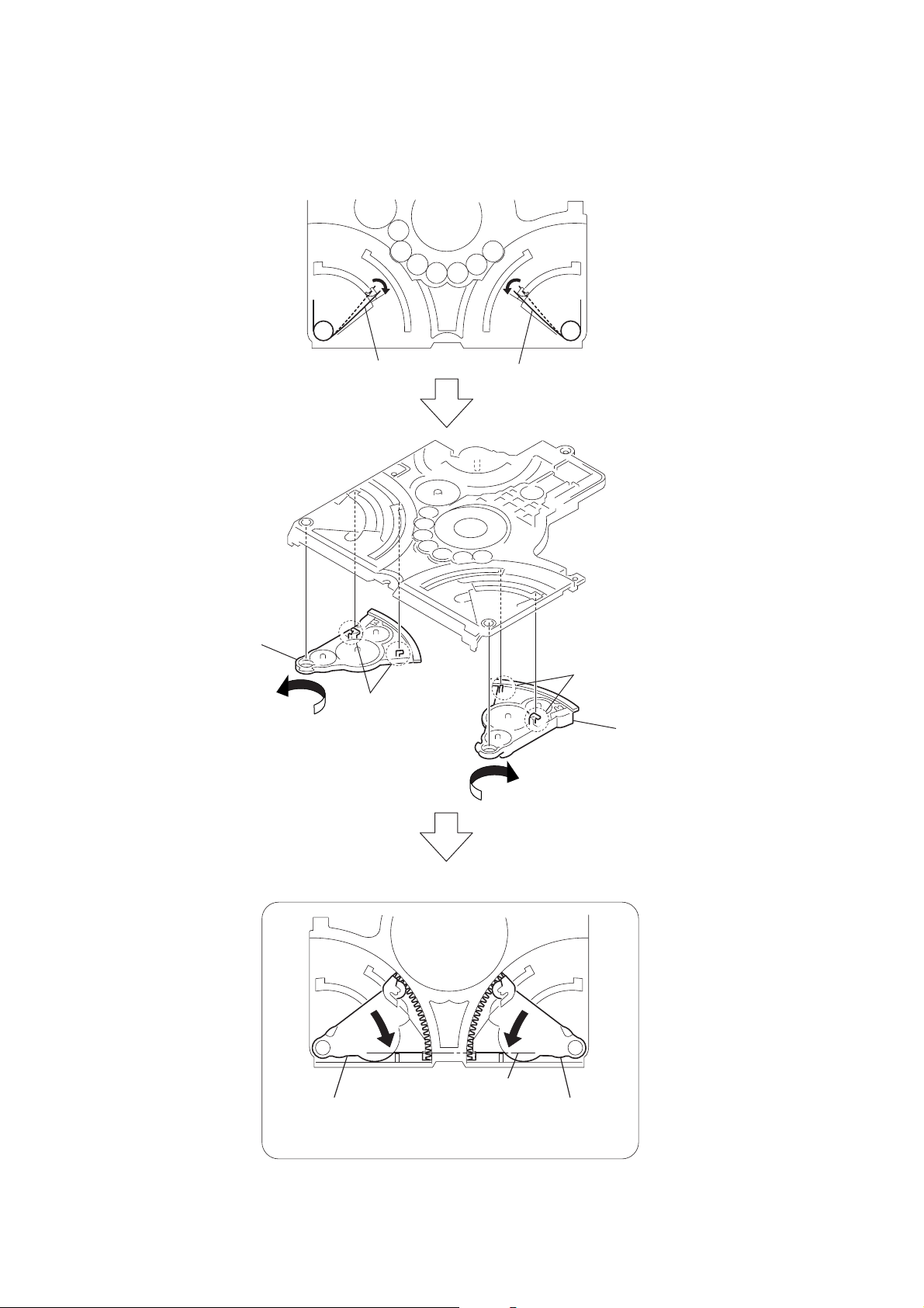
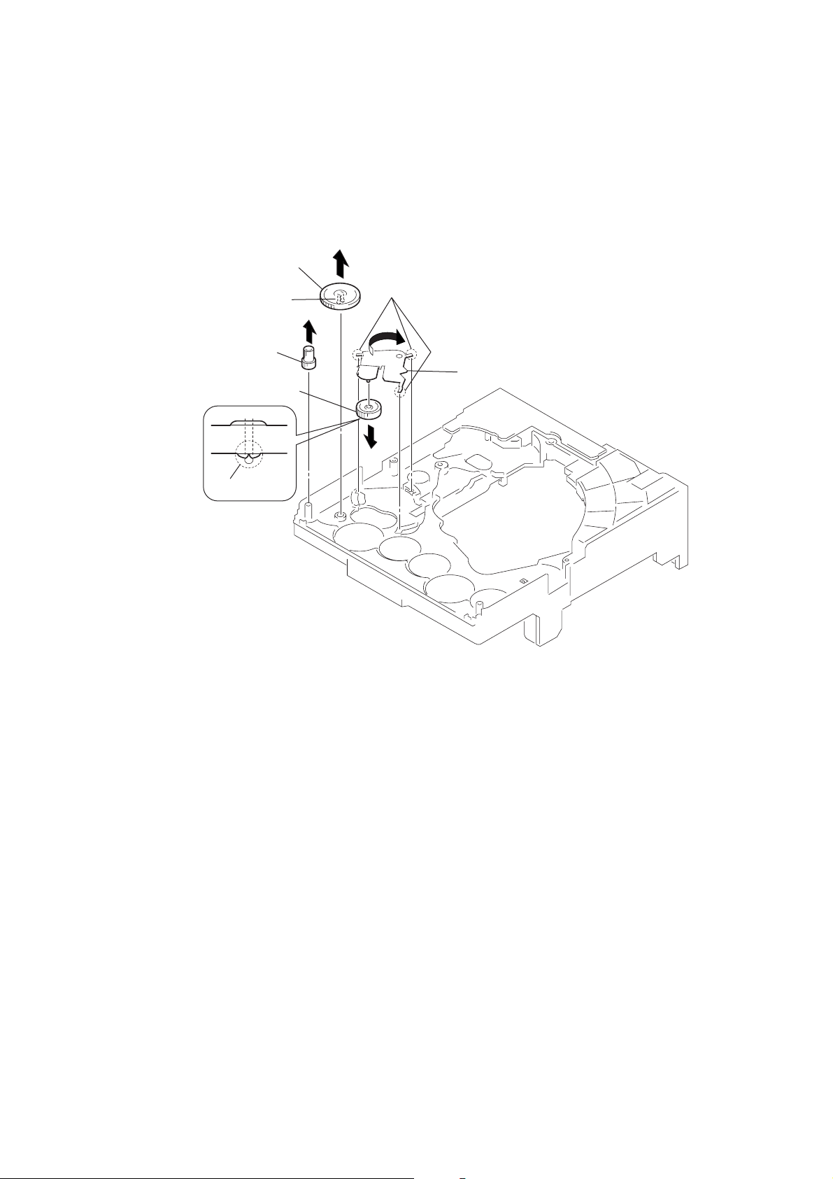
3-8. LEVER (LOADING R/L)
6
lever (loading R)
2
spr-T (loading L) spr-T (loading R)
5
two hooks
1
3
two hooks
4
lever (loading L
16
PRECAUTION DURING LEVER (LOADING R / L) INSTALLATION
Align the horizontal position.
lever (loading L)
Install the
both levers so that they move symmetrically.
lever (loading R)
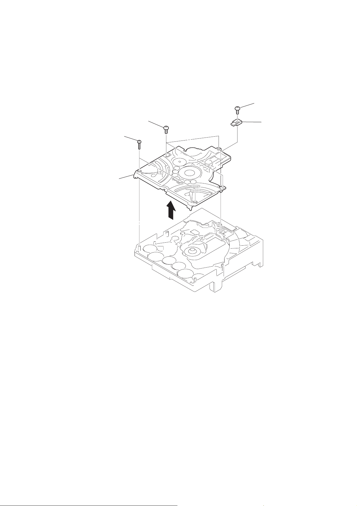
3-9. DISC STOP LEVER, DISC SENSOR LEVER
)
1
gear (cap)
2
gear (IDL L)
HCD-CPX11
PRECAUTION DURING DISC STOP LEVER INSTALLATION
5
two hooks
6
disc stop lever
3-10. DRIVER BOARD
3
Remove soldering
from the two points.
3
two claws
4
disc sensor lever
hole
hole
Install the disc stop lever so that the both holes
are aligned.
2
three screws
(+BVTP 2.6
5
DRIVER board
chassis (top)
disc stop lever
×
8
4
motor (pully) assy
1
belt (MOT)
17
HCD-CPX11
)
3-11. BD81A BOARD
6
3
wire (flat type)
(16 core) (CN102)
1
screw
(+BVTP 2.6
BD81A board
×
8)
2
Remove soldering
from the four points.
4
sheet
5
wire (flat type)
(16 core)
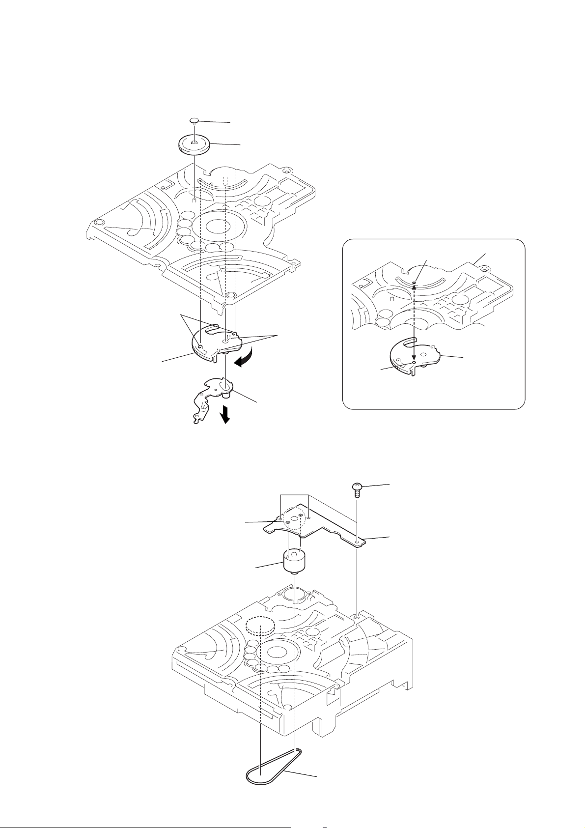
3-12. BU SECTION
6
BU section
4
floating screw
(+PTPWHM 2.6)
3
213 holder down spring
5
floating screw
(+PTPWHM 2.6
18
2
lever (CL UP2)
1
screw
(+BVTP 2.6
×
8)
3-13. OPTICAL PICK-UP (KSM-215DCP)
1
two screws
(+BVTP 2.6
×
8)
4
two floating screws
(+PTPWHM 2.6)
5
two coil springs (insulator)
3
two coil springs (insulator)
6
two insulators
7
two insulators
8
optical pick-up
2
two stoppers (BU)
HCD-CPX11
3-14. LEVER (BU LOCK)
4
lever (BU lock)
2
1
gear (cap)
gear (BU lock)
3
three hooks
2
19
HCD-CPX11
3-15. CLOSE LEVER
3
5
claw
close lever
1
washer (3-1-0.4)
2
4
shaft disc stop
close lever spring
3-16. DIR LEVER, GEAR (IDL-B)
1
6
Loosen the screw.
2
claw
9
DIR lever
DIR spring
3
gear puley
4
gear (cap)
5
gear (IDL-A)
q;
gear (IDL-B)
8
stopper
20
7
Hold the Release lever
and change the direction.
3-17. GEAR (IDL-C)
1
3
gear (IDL-D)
2
two claws
gear (IDL-F)
7
gear (IDL-C)
4
three hooks
5
gear loading lever
HCD-CPX11
6
claw
21

HCD-CPX11
SECTION 4
TEST MODE
[CMN (MC) TEST MODE]
•This mode is used to check operations of Amplifier.
Procedure:
1. Press the ?/1 key to turn the power ON.
2. Press three keys of [DSGX], [FUNCTION] and [TUNER/BAND]
simultaneously.
3. When the CMN (MC) test mode is activated, “s” blinks
on the liquid crystal display.
4. Turn the [BASS] knob counterclockwise, “TONE MIN” is
displayed on the liquid crystal display. Turn the [BASS] knob
clockwise, “TONE MAX” is displayed on the liquid crystal
display.
Turn the [TREBLE] knob clockwise or counterclockwise,
“TONEFLAT” is displayed on the liquid crystal display.
Turn the [VOLUME] knob counterclockwise, “VOL MIN” is
displayed on the liquid crystal display. Turn the [VOLUME]
knob clockwise, “VOL MAX” is displayed on the liquid crystal
display.
5. To release this mode, press the ?/1 key.
[PANEL (GC) TEST MODE]
•This mode is used to check the liquid crystal display, LED,
model, destination, software version and key.
Procedure:
1. Press the ?/1 key to turn the power ON.
2. Press three keys of [DSGX], [DISPLAY] and [FUNCTION]
simultaneously.
3. Liquid crystal display and LEDs are all turned on.
4. When you want to enter the model, destination and version
display mode, press the [REPEAT] key. The model and
destination are displayed alternately on the liquid crystal
display.
5. Each time [REPEAT] key is pressed, the display changes
starting from MD version, MC version, GC version, CD
version, CDD version, CDMA version, CDMB version, BDA
version, BDB version, ST version, TA version, TM version,
and TC version this order, and returns to the MD version
display on the liquid crystal display.
6. When [FUNCTION] key is pressed while the version numbers
are being displayed except model and destination, year, month
and day of the software creation display. When [FUNCTION]
key is pressed again, the display returns to the software version
display. When [REPEAT] key is pressed while year, month
and day of the software creation are being displayed, the year,
month and day of creation of the software versions are
displayed on the liquid crystal display in the same order of
version display.
7. Press the [PLAY MODE/DIRECTION] key, the key check mode
is activated.
8. In the key check mode, the liquid crystal display displays “K0”.
Each time a key is pressed, “K” value increases. However,
once a key is pressed, it is no longer taken into account.
9. To release this mode, press three keys in the same manner as
step 2, or disconnect the power cord.
[SHIP MODE (NO MEMORY CLEAR) ]
•This mode moves the optical pick-up to the position durable
to vibration. Use this mode when returning the set to the
customer after repair.
Procedure:
1. Press the ?/1 key to turn the power ON.
2. Press the [FUNCTION] key to select “CD”.
3. Press three keys of [DSGX], CD NX and [DISPLAY]
simultaneously.
4. After the “ST ANDBY” displa y blinks, “LOCK” is displayed
on the liquid crystal display, and the ship mode is set.
[SHIP MODE (MEMORY CLEAR) ]
•This mode moves the optical pick-up to the position durable
to vibration. Use this mode when returning the set to the
customer after repair.
Procedure:
1. Press the ?/1 key to turn the power ON.
2. Press the [FUNCTION] key to select “CD”.
3. Press three keys of [DSGX], x (CD) and [DISPLAY] simulta-
neously.
4. After the “ST ANDBY” displa y blinks, “LOCK” is displayed
on the liquid crystal display, and the ship mode is set.
[CD TRAY LOCK MODE]
•This mode is used to unable to take sample disc out of tray in
the shop.
Procedure:
1. Press the ?/1 key to turn the power ON.
2. Press the [FUNCTION] key to select “CD”.
3. While pressing the Z (CD) key, press the x (CD) key for
5 seconds.
4. The message “LOCKED” is displayed on the liquid crystal
display and the tray is locked. (Even if pressing the Z (CD)
key, the message “LOCKED” is displayed on the liquid crystal
display and the tray is locked)
5. To release from this mode, pressing the Z (CD) key, press
the x (CD) key for 5 seconds.
6. The message “UNLOCKED” is displayed on the liquid crystal
display and the tray is unlocked.
[TUNER STEP CHANGE MODE]
(Singapore, Korean and Australian models)
•A step of AM channels can be changed over between 9 kHz
and 10 kHz.
Procedure:
1. Press the ?/1 key to turn the power ON.
2. Press the [FUNCTION] key to select “TUNER”, and press the
[TUNER/BAND] key to select “AM”.
3. Press the ?/1 key to turn the power OFF.
4. Press two keys of ?/1 and M L simultaneously.
5. The message “AM 9K STEP” or “AM 10K STEP” is displayed
on the liquid crystal display, and thus the channel step is
changed over.
[COLD RESET]
• The cold reset clears all data including preset data stored in
the RAM to initial conditions. Execute this mode when
returning the set to the customer.
Procedure:
1. Press the ?/1 key to turn the power ON.
2. Press three keys of ?/1 , x (CD) and x (TAPE) simultaneously.
3. The liquid crystal display becomes blank instantaneously, and
the set is reset.
22
[CD SERVICE MODE]
•This mode can run the CD sled motor freely. Use this mode,
for instance, when cleaning the optical pick-up.
Procedure:
1. Press the ?/1 key to turn the power ON.
2. Press the [FUNCTION] key to select “CD”.
3. Press three keys of [DSGX] , [DISPLAY] and M L si-
multaneously.
4. Press the M L key to move the optical pick-up to outside
track, or press the l m key to inside track.
5. To release this mode, press the ?/1 key.
HCD-CPX11
[AGING MODE]
• This mode can be used for operation check of CD section and
tape deck section.
CD section and tape deck section work in parallel.
If an error occurred:
The aging operation stops only an error occurred sections and
display then status.
If no error occurs:
The aging operation continues repeatedly.
Procedure:
1. Press the ?/1 key to turn the power ON.
2. Press the [FUNCTION] key to select “CD”.
3. Set disc on the tray and set tape into the deck.
4. Press the [REPEAT] key to “REPEAT” off.
5. Press three keys of [DSGX], [PLAY MODE/DIRECTION]
and x (TAPE) simultaneously.
6. Aging operations of CD and tape are started at the same time.
7. To release this mode, press the ?/1 key.
1. Display at the Aging Mode
Display operating state of CD section and tape deck section
alternately.
If an error occurred, stop display which that section.
2. CD Section
The sequence during the aging mode is following as below.
Display at the aging mode is the same as the normal operation.
Aging mode sequence (CD section) :
Start
Disc chucking
TOC read
Play first track for 2 seconds
3. Tape Deck Section
The sequence during the aging mode is following as below.
If an error occurred, stop display that step.
Display at the aging mode is “TAPE AG—”.
Aging mode sequence (Tape deck section) :
Start
Rewind the tape
Shut off
FWD play the tape
2 minutes
Fast forward the tape
Shut off or 20 seconds
REV play the tape
2 minutes
[CD ERROR CODE MODE]
• This mode can be used for error display of CD section.
Procedure:
1. Press the ?/1 key to turn the power ON.
2. Press the [FUNCTION] key to select “CD”.
3. Press three keys of [DSGX] , [DISPLAY] and l m simultaneously.
Note: Error code is not displayed on the liquid crystal display.
[CD SERVO TEST MODE]
•This mode used to ckeck operation of optical pick-up.
Procedure:
1. Press the ?/1 key to turn the power ON.
2. Press the [FUNCTION] key to select “CD”.
3. Press three keys of [DSGX] , [FUNCTION] and x (TAPE)
simultaneously.
4. When the CD servo test mode is activated, optical pick-up
moves.
Play last track for 2 seconds
Open the disc tray
Close the disc tray
[5 REPEAT OFF MODE]
• Number of repeat for CD playback is 5 times when the repeat
mode is “REPEA T”. This mode is used to enables CD to repeat
playback for limitless times.
Procedure:
1. Press the ?/1 key to turn the power on.
2. Press the [FUNCTION] key to select “CD”.
3. Press three keys of [DSGX] , [FUNCTION] and Z (CD)
simultaneously.
4. When the 5 repeat off mode is activated, “LIMIT OF” is
displayed on the liquid crystal display.
[CHANGE-OVER FUNCTION OF EXTERNAL INPUT]
•This mode is used to enable function of external input to change
over between MD and VIDEO.
Procedure:
1. Set to standby state.
2. Press two keys of ?/1 and [FUNCTION] simultaneously.
3. The function of external input changes over to MD or VIDEO.
23
HCD-CPX11
e
SECTION 5
ELECTRICAL ADJUSTMENTS
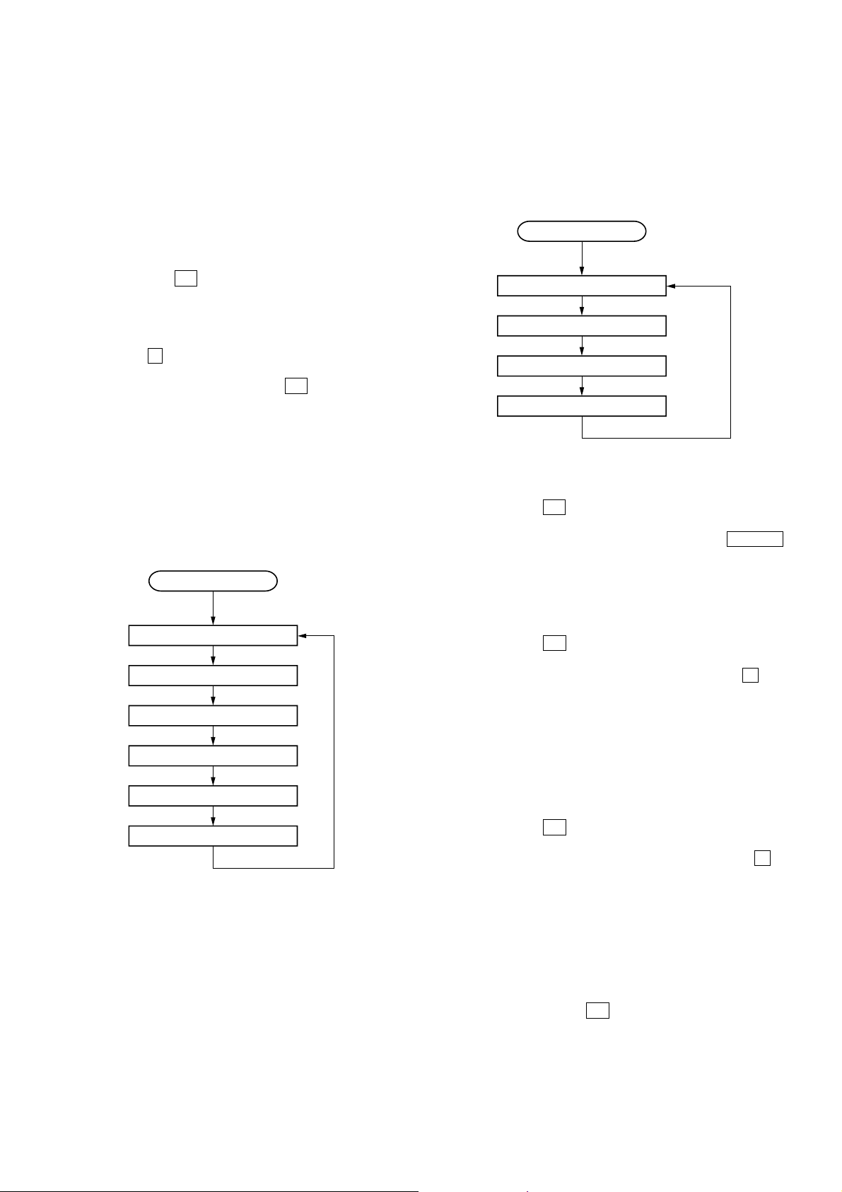
DECK SECTION 0 dB = 0.775 V
Note:
Confirm each contents of this section first of all. If the results are
not satisfied, do the adjustment.
1. The adjustments should be performed with the rated power
supply voltage unless otherwise noted.
2. The adjustments should be performed in the order given in
this service manual.
3. The adjustments should be performed for both L-CH and RCH.
REC BIAS ADJUSTMENT
Procedure:
1. Press the [FUNCTION] key to select “MD” or “VIDEO”.
2. Set the tape into the deck.
3. After pressing z REC key, press X (TAPE) key to start
recording.
4. Mode: Record
MAIN board
MD (VIDEO) IN jack (J101)
L-CH, R-CH
34.6 mV (– 27 dB)
600
Ω
set
blank tap
CN-123
AF OSC
1) 315 Hz
2) 10 kHz
attenuator
– TC BOARD (Component Side) –
(R-CH)
REC Bias
Adjustment
(L-CH)
RV603
RV653
5. Mode: Playback
recorded
portion
set
SP board
SPEAKER terminals (J860)
L-CH, R-CH
level meter
+
–
6. Confirm the playback signal recorded in step 3 becomes
adjustable level as follows.
If these levels are out of specified values, adjust the RV653
(L-CH) and R V603 (R-CH) on the TC board to repeat steps 4
and 5.
Specified values: Playback output of 315 Hz to playback
output of 10 kHz: ± 2.0 dB
Adjustment Location: TC board
24
Loading...