


HCD-D690
Table of contents
 Loading...
HCD-D690/XB6/XB600
SERVICE MANUAL
HCD-D690, HCD-XB6, HCD-XB600 are
the tuner, deck, CD and amplifier section
in LBT-D690, LBT-XB6, LBT-XB600.
Photo: HCD-XB6
CD
Section
Tape deck
Section
US Model
Canadian Model
HCD-D690
AEP Model
UK Model
E Model
Australian Model
HCD-XB6
Mexican Model
HCD-XB600
Model Name Using Similar Mechanism HCD290/G330/XB3
CD Mechanism Type
Base Unit Name BU-5BD29AL
Optical Pick-up Name
Model Name Using
T ape Transport Mechanism T ype TCM-220WR2
Similar Mechanism HCD-H881
CDM37L-5BD29AL
KSS-213D/Q-NP
SPECIFICATIONS
For the US model
AUDIO POWER SPECIFICATIONS
POWER OUTPUT AND TOTAL HARMONIC DISTORTION:
With 8 ohm loads, both channels driven, from 70-20,000 Hz; r ated 100 watts
per channel minimum RMS power, with no more than 0.9 % total harmonic
distortion from 250 milliwatts to rated output.
Amplifier section
DIN power output
AEP , UK, East European, CIS models:100+100 watts (6 ohms at 1 kHz, DIN)
Continuous RMS power output
Canadian model: 100+100 watts
(8 ohms at 1 kHz, 5%)
Argentine, Australian, E, Mexican
models: 100+100 watts
(8 ohms at 1kHz, 10% THD)
AEP, UK, East European, CIS models:120+120 watts
(6 ohms at 1kHz, 10% THD)
Peak music power output
Argentine, Australian, E, Mexican
models: 1400 watts
Music power output
AEP, UK, East European, CIS models:210+210 watts
Inputs
PHONO IN (phono jacks): sensitivity 3 mV, impedance 47 kilohms
VIDEO (AUDIO) IN (phono jacks): sensitivity 250 mV, impedance 47 kilohms
MIX MIC (phono jack): sensitivity 1 mV, impedance 10 kilohms
Outputs
PHONES (stereo phone jack): accepts headphones of 8 ohms or more
SPEAKER: accepts impedance of 8 to 16 ohms
SURROUND SPEAKER: accepts impedance of 16 ohms
– Continued on next page –
COMPACT DISC DECK RECEIVER
MICROFILM

CD player section
System Compact disc and digital audio system
Laser Semiconductor laser (λ = 780nm).
Emission duration: continuous
Laser output Max. 44.6µF*
*This output is the value measured at a distance
of 200 mm from the objective lens surface on the
Optical Pick-up Block with 7 mm aperture.
Wavelength 780 - 790 nm
Frequency response 2 Hz - 20 kHz (±0.5 dB)
Signal-to-noise ratio More than 90 dB
Dynamic range More than 90 dB
Tape player section
Recording system 4-track 2-channel stereo
Frequency response (DOLBY NR OFF)
60 - 13,000 Hz (±3 dB), using a Sony
TYPE I cassette
60 - 14,000 Hz (±3 dB), using a Sony
TYPE II cassette
Wow and flutter ±0.15% W. Peak (IEC)
0.1% W. RMS (NAB)
±0.2% W. Peak (DIN)
Tuner section
FM stereo, FM/AM superheterodyne tuner
FM tuner section
Tuning range
US, Canadian models: 87.5 - 108.0 MHz (100 kHz step)
AEP, UK models: 87.5 - 108.0 MHz (50 kHz step)
East European, CIS models:
FM: 87.5 -108.0 MHz (50 kHz step)
65.0 - 74.0 MHz (10 kHz step) OIRT
UKV: 65.0 - 74.0 MHz (10 kHz step)
POLAR STEREO
Other models: 87.5 -108.0 MHz (50 kHz step)
Antenna FM wire antenna
Antenna terminals 75 ohm unbalanced
Intermediate frequency 10.7 MHz
AM tuner section
Tuning range
US, Canadian models: 530 - 1,710 KHz (with the tuning interval set at
10 kHz)
531 - 1,710 KHz (with the tuning interval set at 9
kHz)
AEP, UK, East European,
CIS models:
MW: 531 - 1,602 kHz
(with the tuning interval set at 9 kHz)
LW: 153 - 279 kHz
(with the tuning interval set at 3 kHz)
Other models: 531 - 1,602 kHz
(with the tuning interval set at 9 kHz)
530 - 1,710 KHz
(with the tuning interval set at 10 kHz)
Antenna AM loop antenna, External antenna terminals
Intermediate frequency 450 kHz
General
Power requirements
US, Canadian models: 120 V AC, 60 Hz
Mexican model: 120 V AC, 50/60 Hz
Australian model: 220 - 240 V AC, 50/60 Hz
AEP, UK, East European,
CIS models: 220 - 230 V AC, 50/60 Hz
Other models: 110 - 120 V or 220 - 240 V
AC, 50/60 Hz Adjustable with voltage selector
Power consumption
US, Canadian models: 198 watts
AEP, UK, East European,
CIS models: 230 watts
Other models: 190 watts
Dimensions (w/h/d) Approx. 355 x 425 x 435 mm (14 x 16
4 in) incl. projecting parts and controls
Mass Approx. 12.5 kg (27 lb 9 oz.)
Supplied accessories: AM loop antenna (1)
Remote RM-SD70 (1)
Sony SUM-3 (NS) batteries (2)
FM wire antenna (1)
Speaker cords (2)
Design and specifications are subject to change without notice.
3
/4 x 17 1/
– 2 –
CAUTION
Use of controls or adjustments or performance of
procedures other than those specified herein may
result in hazardous radiation exposure.
Notes on chip component replacement
• Never reuse a disconnected chip component.
• Notice that the minus side of a tantalum capacitor may be dam-
aged by heat.
Flexible Circuit Board Repairing
• K eep the temperature of the soldering iron around 270 ˚C during
repairing.
• Do not touch the soldering iron on the same conductor of the
circuit board (within 3 times).
• Be careful not to apply force on the conductor when soldering or
unsoldering.
This appliance is classified as a CLASS 1 LASER product.
The CLASS 1 LASER PRODUCT MARKING is located on
the rear exterior.
SAFETY CHECK-OUT
After correcting the original service problem, perform the following safety check before releasing the set to the customer:
Check the antenna terminals, metal trim, “metallized” knobs, screws,
and all other exposed metal parts for AC leakage.
Check leakage as described below.
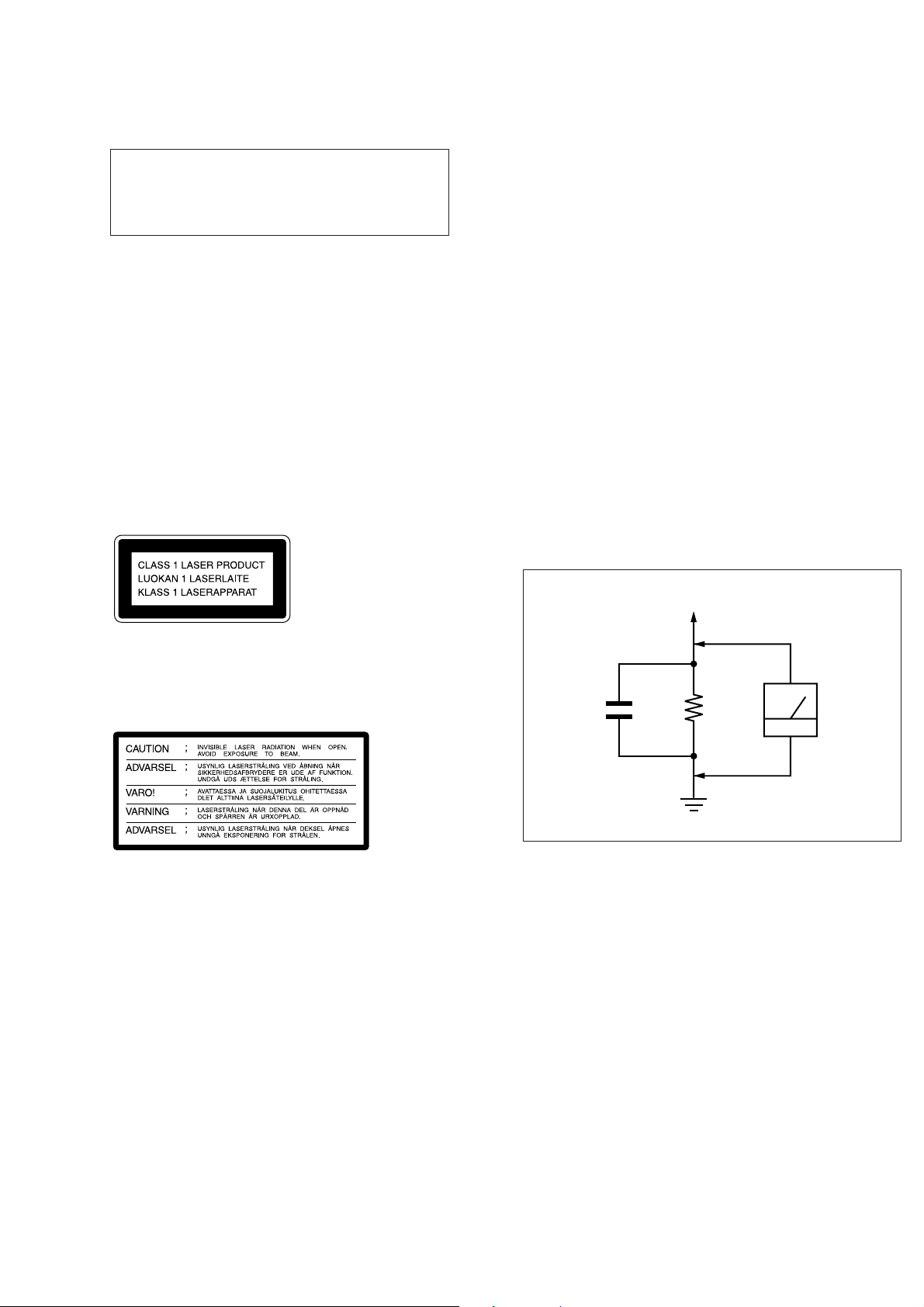
LEAKAGE TEST
The AC leakage from any exposed metal part to earth ground and
from all exposed metal parts to any exposed metal part having a
return to chassis, must not exceed 0.5 mA (500 microampers.). Leakage current can be measured by any one of three methods.
1. A commercial leakage tester, such as the Simpson 229 or RCA
WT-540A. Follow the manufacturers’ instructions to use these
instruments.
2. A battery-operated AC milliammeter. The Data Precision 245
digital multimeter is suitable for this job.
3. Measuring the voltage drop across a resistor by means of a V OM
or battery-operated A C voltmeter. The “limit” indication is 0.75
V, so analog meters must have an accurate low-voltage scale.
The Simpson 250 and Sanwa SH-63Trd are examples of a passive VOM that is suitable. Nearly all battery operated digital
multimeters that have a 2 V AC range are suitable. (See Fig. A)
To Exposed Metal
Parts on Set
Laser component in this product is capable of emitting radiation
exceeding the limit for Class 1.
The following caution label is located inside the unit.
Dolby noise reduction manufactured under license from Dolb y
Laboratories Licensing Corporation.
“DOLBY” and the double-D symbol a are trademarks of Dolby
Laboratories Licensing Corporation.
SAFETY-RELATED COMPONENT WARNING!!
COMPONENTS IDENTIFIED BY MARK ! OR DOTTED
LINE WITH MARK ! ON THE SCHEMATIC DIAGRAMS
AND IN THE PARTS LIST ARE CRITICAL TO SAFE
OPERATION. REPLACE THESE COMPONENTS WITH
SONY PARTS WHOSE PART NUMBERS APPEAR AS
SHOWN IN THIS MANUAL OR IN SUPPLEMENTS PUBLISHED BY SONY.
AC
0.15 µF
1.5 k
Ω
Earth Ground
voltmeter
(0.75 V)
Fig. A. Using an AC voltmeter to check AC leakage.
ATTENTION AU COMPOSANT AYANT RAPPORT
LES COMPOSANTS IDENTIFIÉS P AR UNE MARQUE !
SUR LES DIAGRAMMES SCHÉMATIQUES ET LA LISTE
DES PIÈCES SONT CRITIQUES POUR LA SÉCURITÉ
DE FONCTIONNEMENT. NE REMPLACER CES COMPOSANTS QUE PAR DES PIÈCES SONY DONT LES
NUMÉROS SONT DONNÉS DANS CE MANUEL OU
DANS LES SUPPLÉMENTS PUBLIÉS PAR SONY.
À LA SÉCURITÉ!
– 3 –
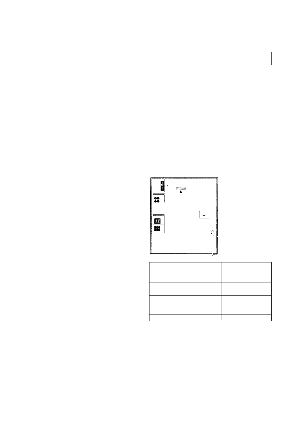
TABLE OF CONTENTS
1. GENERAL
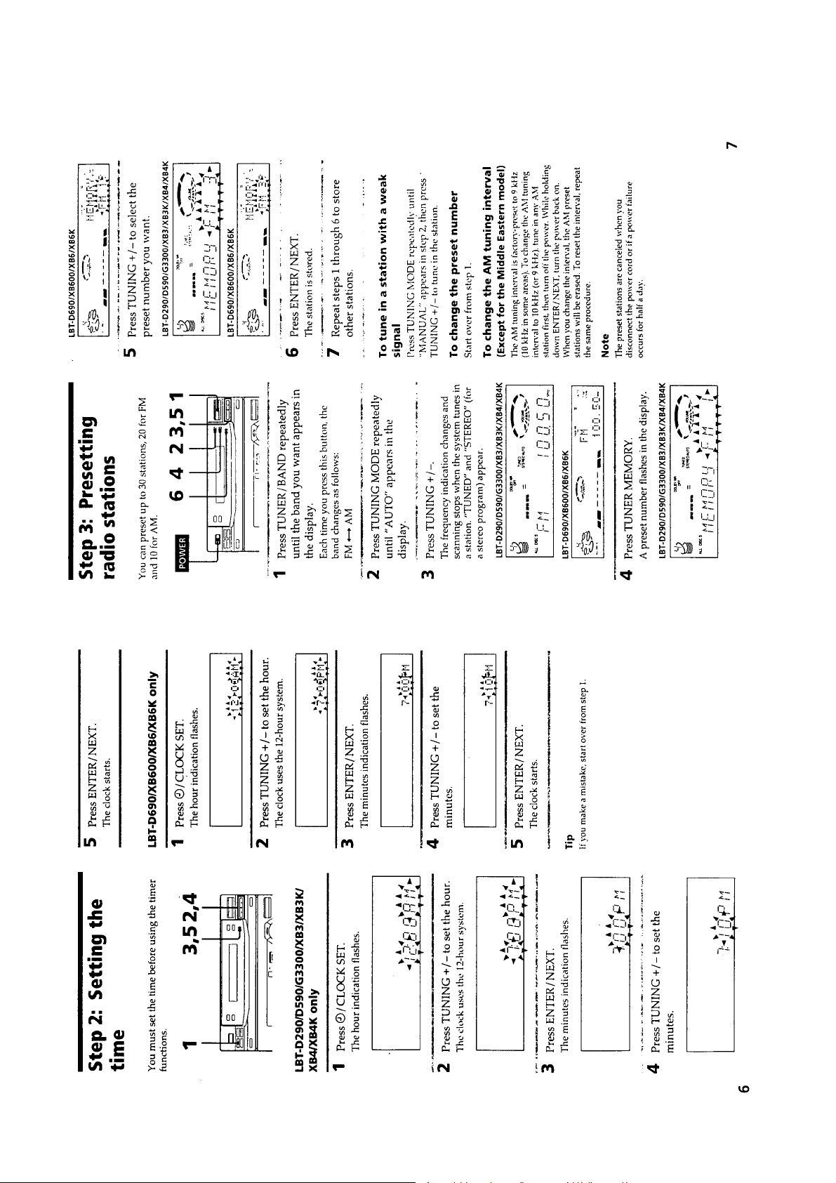
Getting Started ............................................................. 5
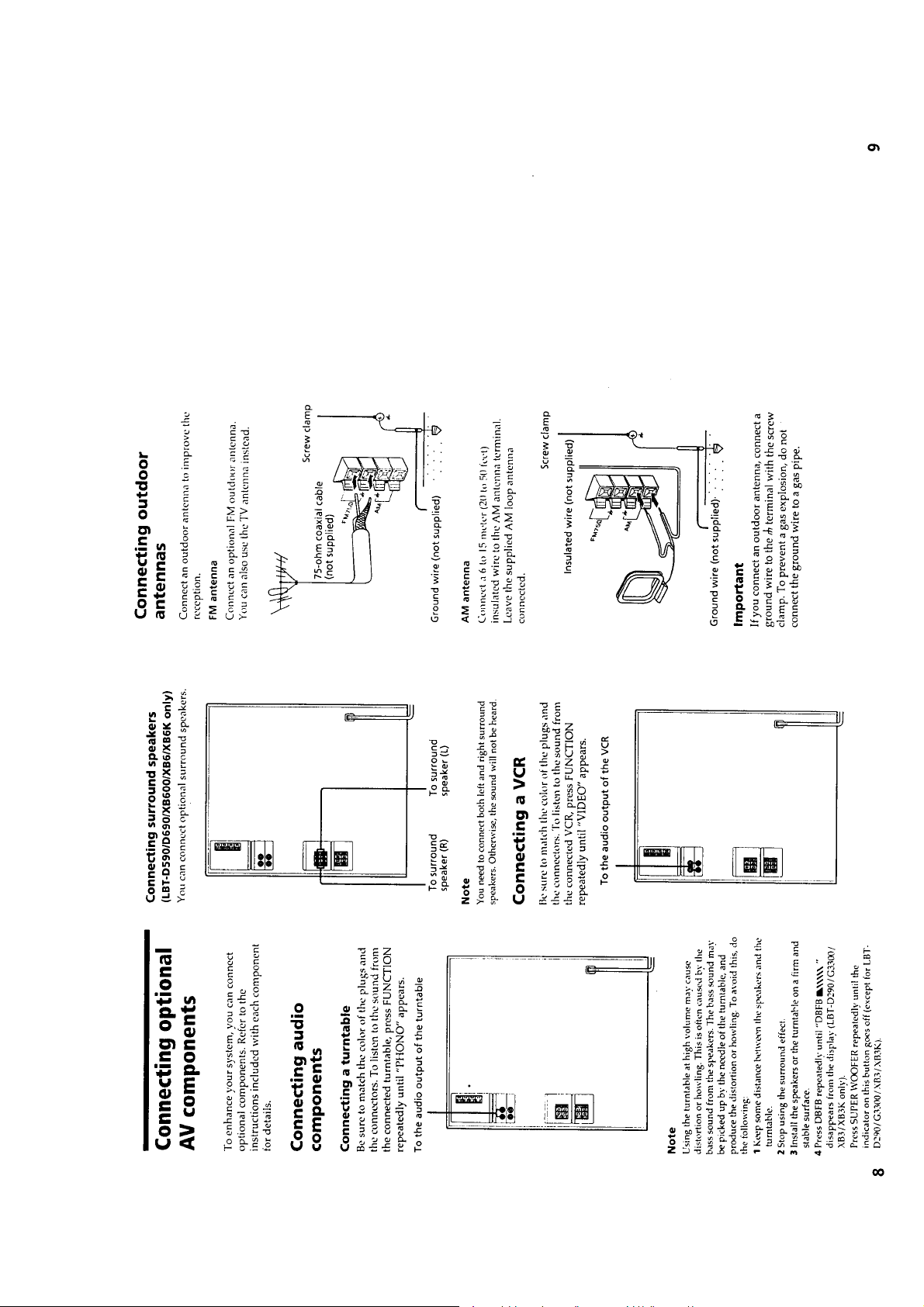
Basic Operations .......................................................... 8
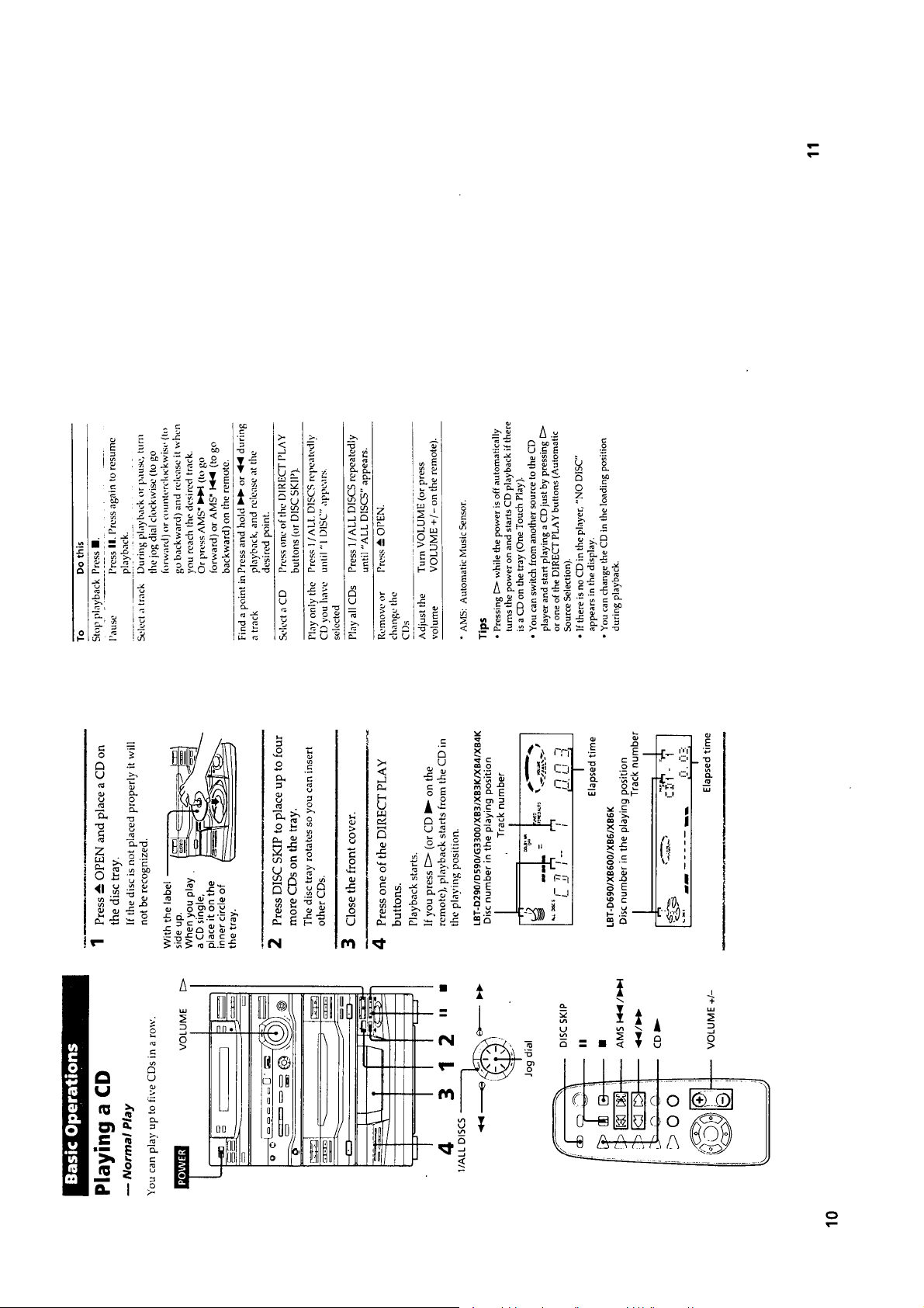
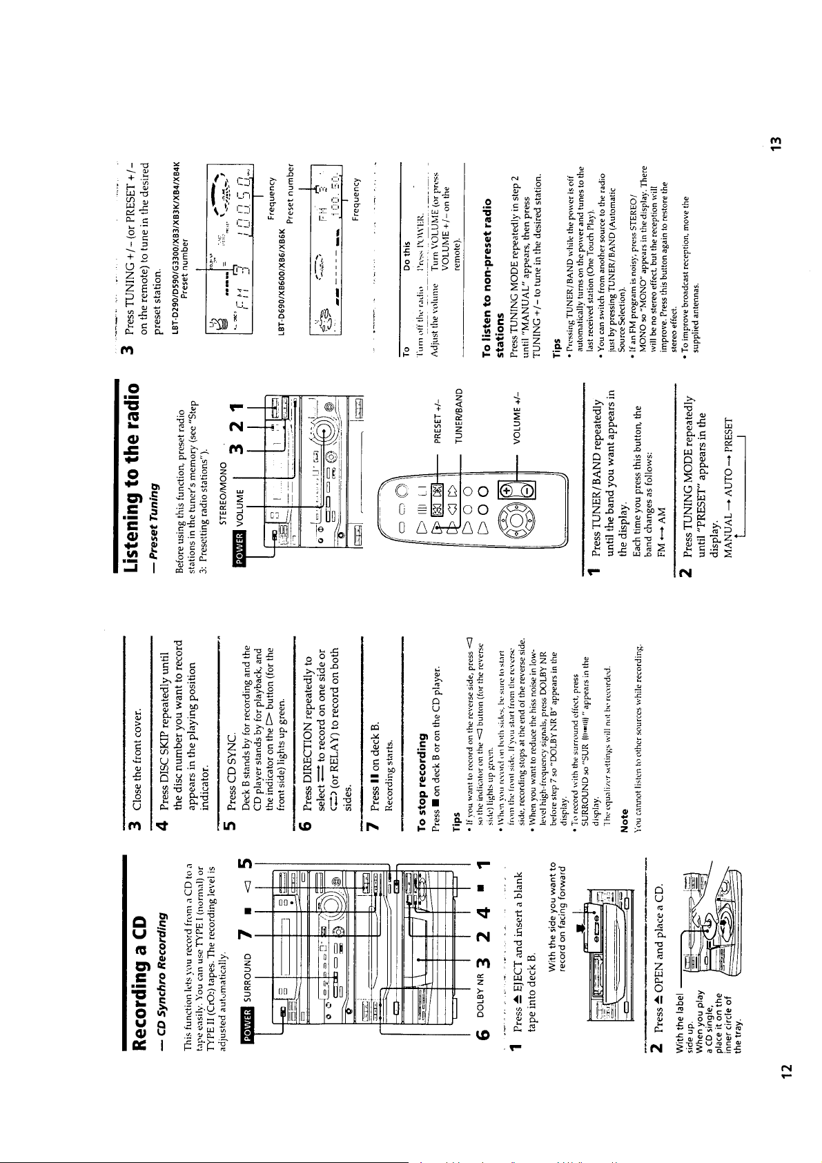
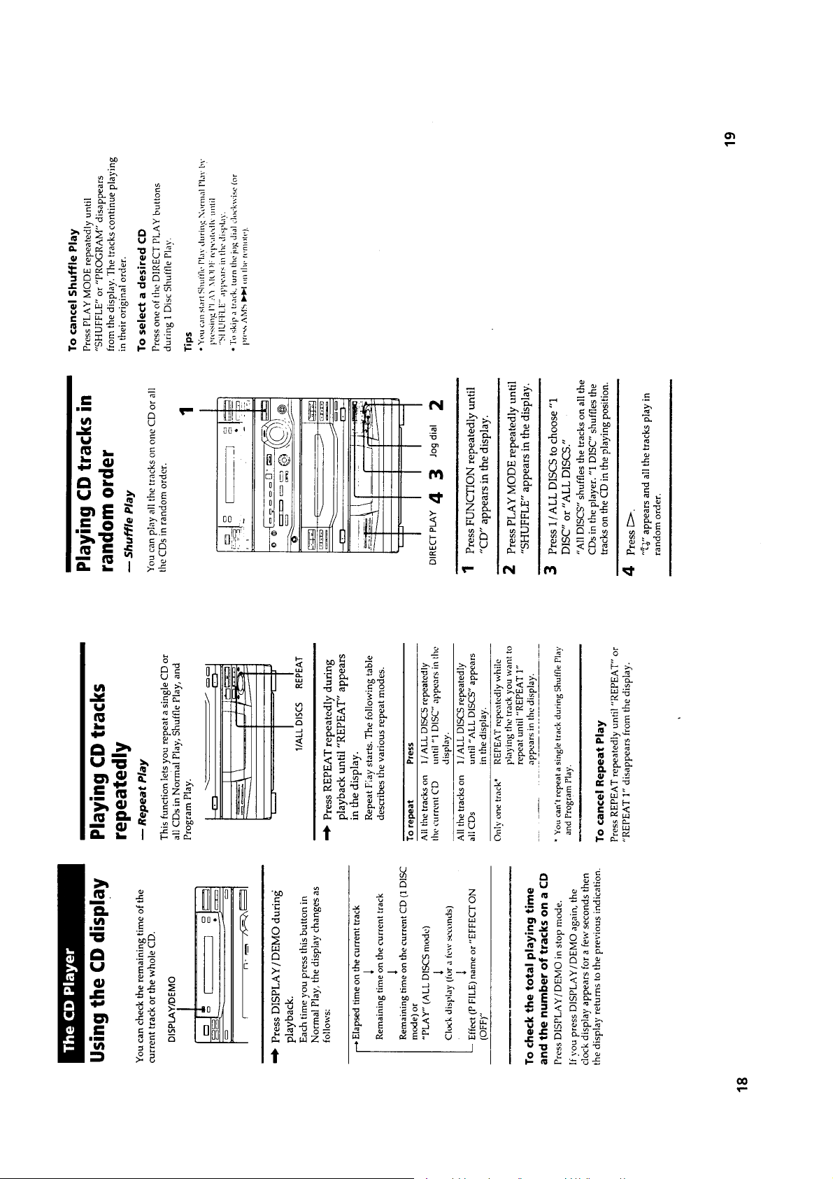
The CD Player ............................................................. 12
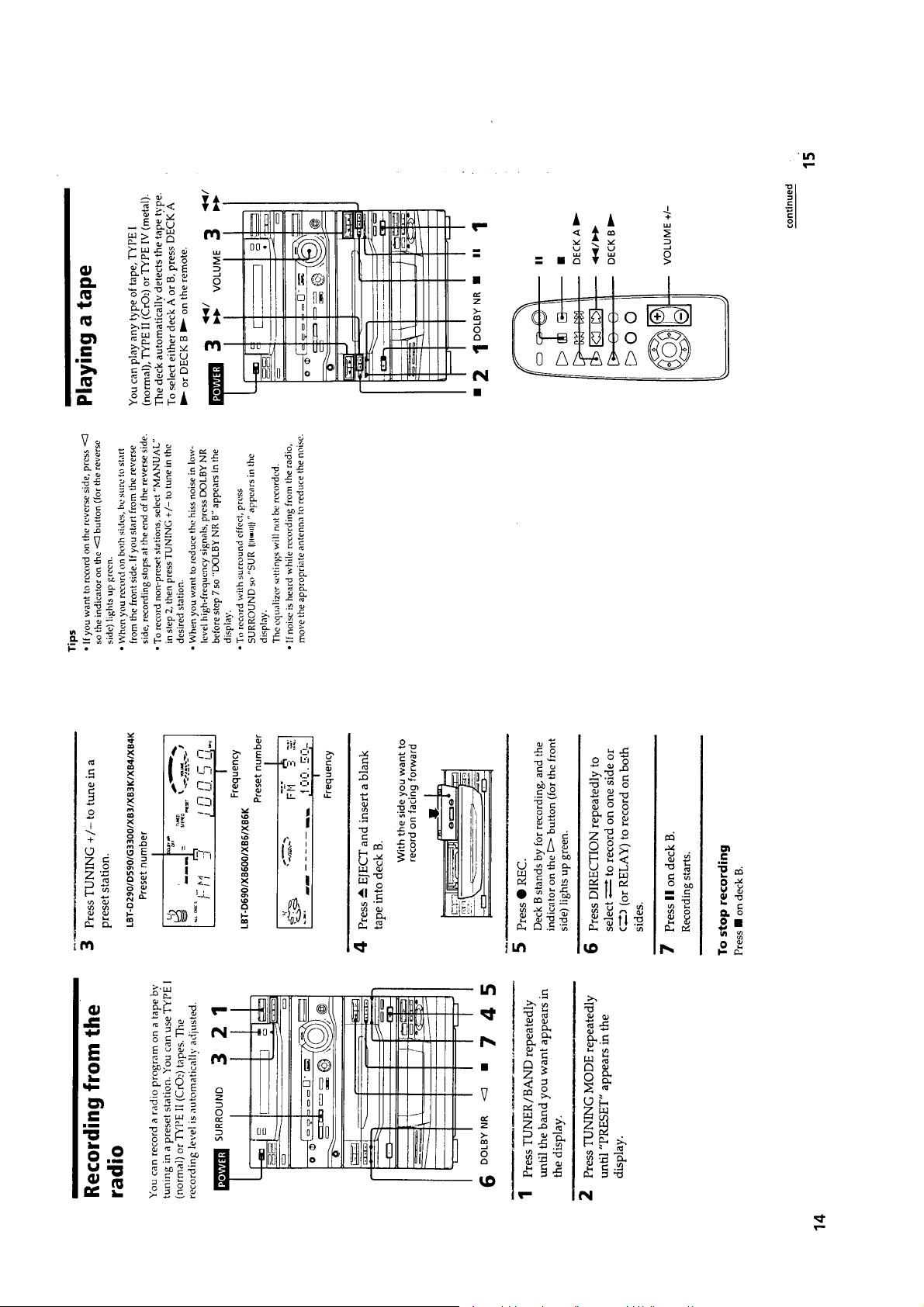
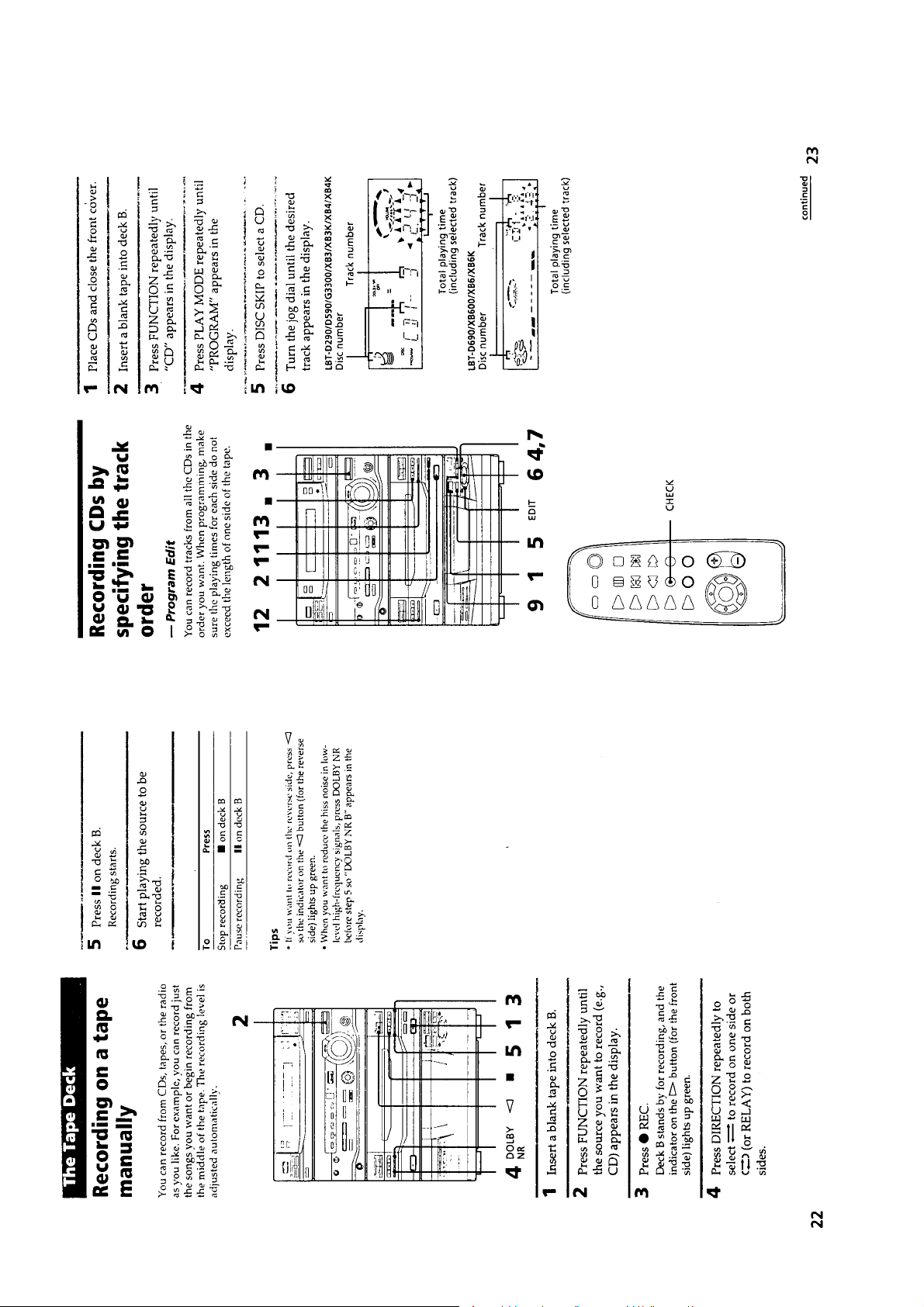
The Tape Deck ............................................................. 14
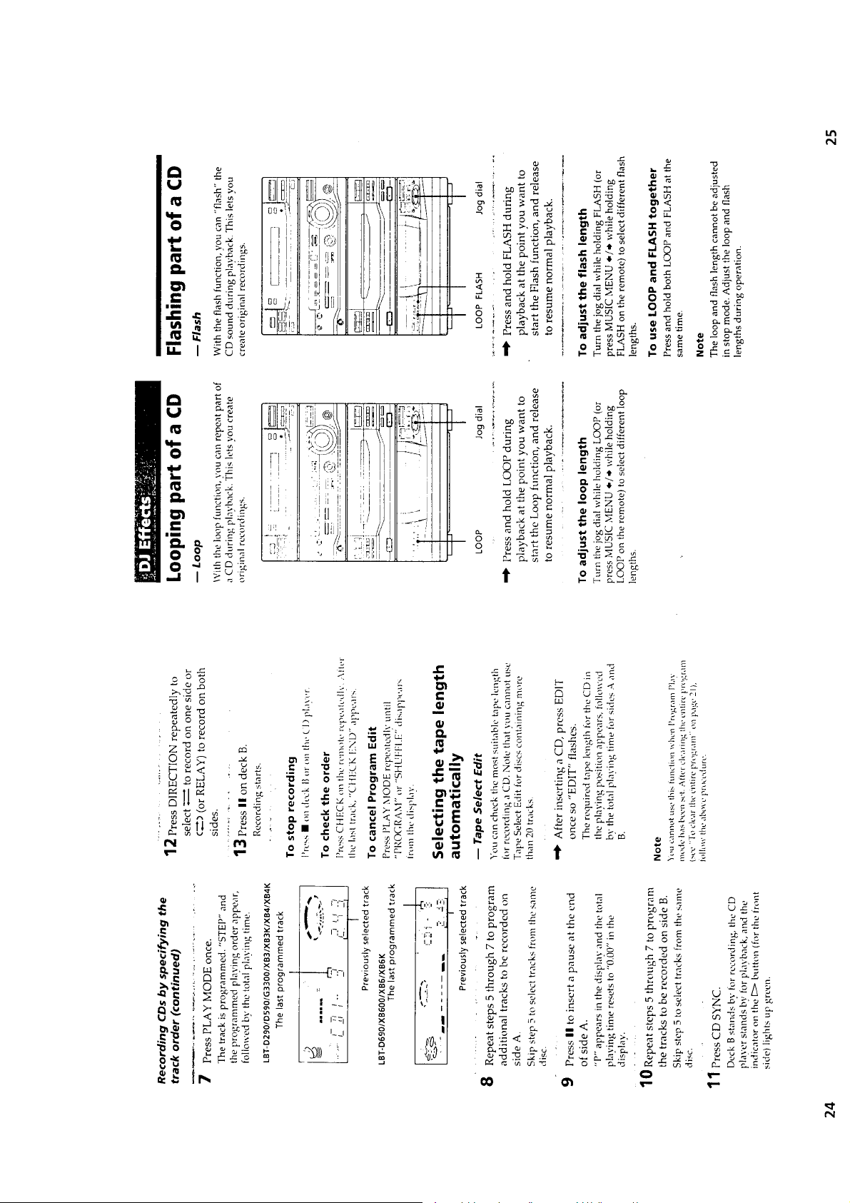
DJ Effects ..................................................................... 15
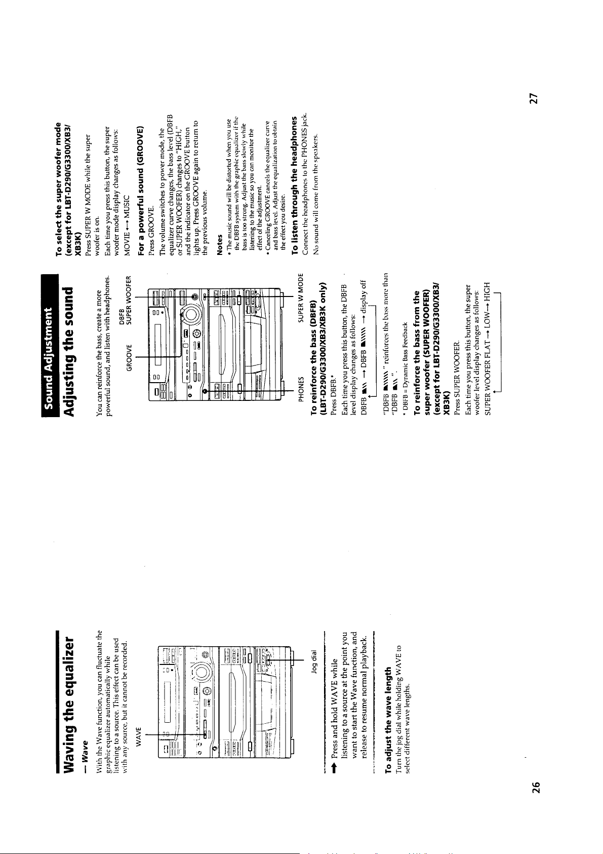
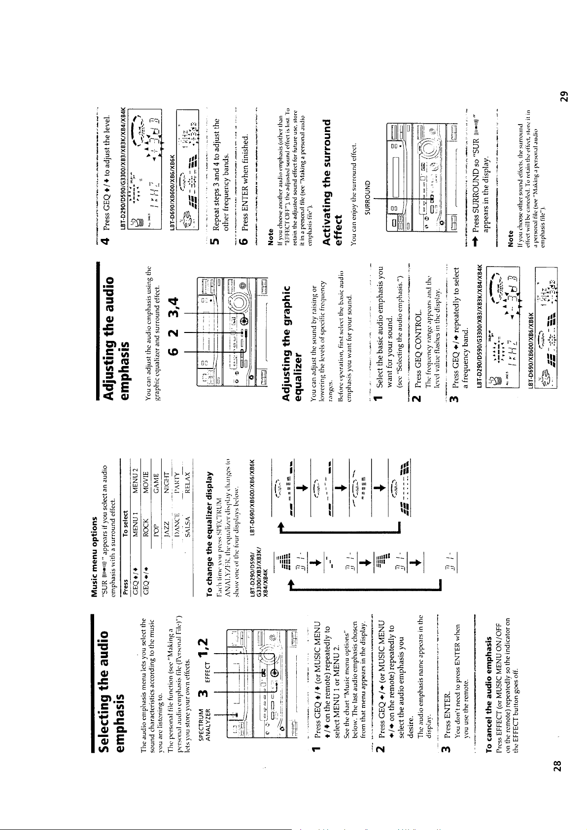
Sound Adjustment ........................................................ 16
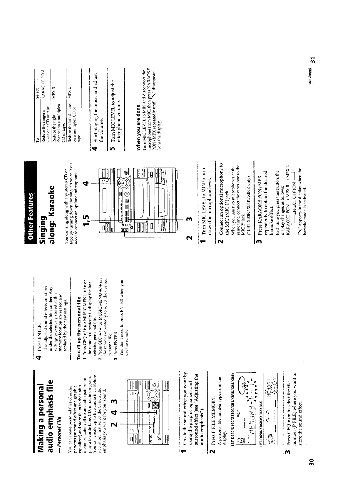
Other Features .............................................................. 18
Additional Information ................................................. 21
2. DISASSEMBLY ...................................................... 22
3. TEST MODE ............................................................ 30
4. MECHANISM ADJUSTMENTS ..................... 32
5. ELECTRICAL ADJUSTMENTS
DECK Section .............................................................. 32
TUNER Section ........................................................... 35
CD Section ................................................................... 37
6. DIAGRAMS
6-1. Block Diagrams
Tuner Section
(US, CND, E, AR, MX, AUS models) ......................... 41
Tuner Section (AEP, UK models) ................................ 42
Tuner Section (EE, CIS models) .................................. 43
CD Section ................................................................... 46
Main Section ................................................................ 47
6-2. Schematic Diagram – BD Section – ............................ 49
6-3. Printed Wiring Board – BD Section – ........................ 51
6-4. Schematic Diagram – CD Motor Section – ................ 53
6-5. Printed Wiring Boards – CD Motor Section – ............. 55
6-6. Schematic Diagram – Tuner Section –
(US, CND, E, AR, MX, AUS models) ......................... 57
6-7. Printed Wiring Board – Tuner Section –
(US, CND, E, AR, MX, AUS models) ......................... 59
6-8. Schematic Diagram – Tuner Section –
(AEP, UK models) ....................................................... 61
6-9. Printed Wiring Board – Tuner Section –
(AEP, UK models) ....................................................... 63
6-10. Schematic Diagram – Tuner Section–
(EE, CIS models) ......................................................... 65
6-11. Printed Wiring Board – Tuner Section –
(EE, CIS models) .......................................................... 67
6-12. Printed Wiring Boards – Deck Section – .................... 69
6-13. Schematic Diagram – Deck Section – ........................ 71
6-14. Schematic Diagram – Main Section – ........................ 75
6-15. Printed Wiring board – Main Section – ...................... 79
6-16. Printed Wiring Boards – Panel Section – .................... 82
6-17. Schematic Diagrm – Panel Section – .......................... 85
6-18. Printed Wiring Boards – Power Section – ................... 89
6-19. Schematic Diagram – Power Section – ....................... 91
6-20. IC Pin Function Description ........................................ 99
SERVICING NOTES
NOTES ON HANDLING THE OPTICAL PICK-UP
BLOCK OR BASE UNIT
The laser diode in the optical pick-up block may suffer electrostatic break-down because of the potential difference generated
by the charged electrostatic load, etc. on clothing and the human
body.
During repair, pay attention to electrostatic break-down and also
use the procedure in the printed matter which is included in the
repair parts.
The flexible board is easily damaged and should be handled with
care.
NOTES ON LASER DIODE EMISSION CHECK
The laser beam on this model is concentrated so as to be focused
on the disc reflective surface by the objective lens in the optical
pick-up block. Therefore, when checking the laser diode emission, observe from more than 30 cm away from the objectiv e lens.
MODEL IDENTIFICATION
– BACK PANEL –
PARTS No.
MODEL PARTS No.
XB6: E, Argentine models 4-987-926-0π
XB6: Australian model 4-987-926-1π
XB6: AEP, UK models 4-987-044-3π
XB6: East European, CIS models 4-987-044-5π
D690: US model 4-987-044-6π
D690: Canadian model 4-987-044-7π
XB6: Mexican model 4-987-926-3π
XB600: Mexican model 4-987-926-8π
7. EXPLODED VIEWS .............................................. 103
8. ELECTRICAL PARTS LIST .............................. 112
• Abbreviation
CND : Canadian model
MX : Mexican model
AUS : Australian model
AR : Argentine model
EE : East European model
– 4 –
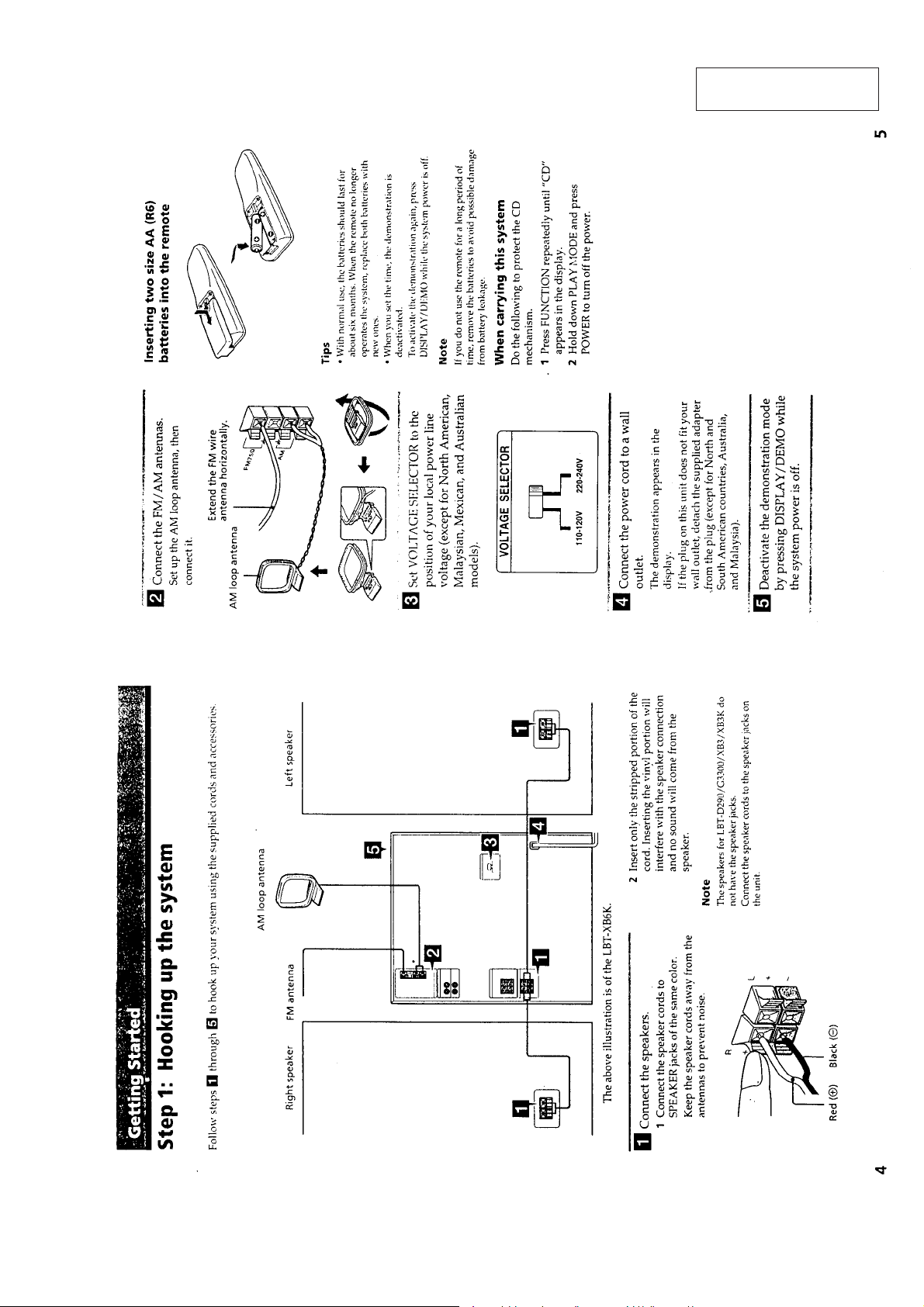
SECTION 1
GENERAL
This section is extracted
from instruction manual.
– 5 –
– 6 –
– 7 –
– 8 –
– 9 –
– 10 –

– 11 –
– 12 –
– 13 –
– 14 –
– 15 –
– 16 –
– 17 –
– 18 –
– 19 –
– 20 –
– 21 –
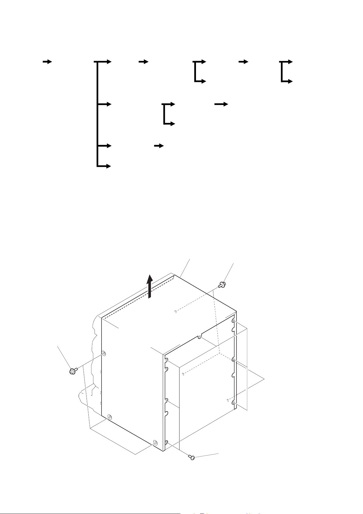
• This set can be disassembled in the order shown below.
(Pag
)
SECTION 2
DISASSEMBLY
CASE
(Page 22)
Note: Follow the disassembly procedure in the numerical order given.
FRONT PANEL
SECTION
(Page 23)
MAIN
SECTION
(Page 24)
TAPE MECHANISM
DECK SECTION
(Page 25)
CD LID ASS’Y
SECTION
(Page 26)
MAIN BOARD
e 23
CD MECHANISM
DECK SECTION
(Page 24)
AUDIO BOARD
(Page 29)
CASSETTE
LID ASS’Y
(Page 25)
PANEL (A)/(B)
SUB ASS’Y
(Page 26)
BASE UNIT
(Page 27)
DISC TABLE
(Page 27)
BD BOARD
(Page 28)
CAPSTAN MOTOR
(Page 29)
OPTICAL
PICK-UP
(Page 28)
SLED
MOTOR
(Page 28)
CASE
1
three screws
(case 3 point)
3
case
three screws
1
(case 3 point)
2
seven screws
(BVTT 3
×
6)
– 22 –
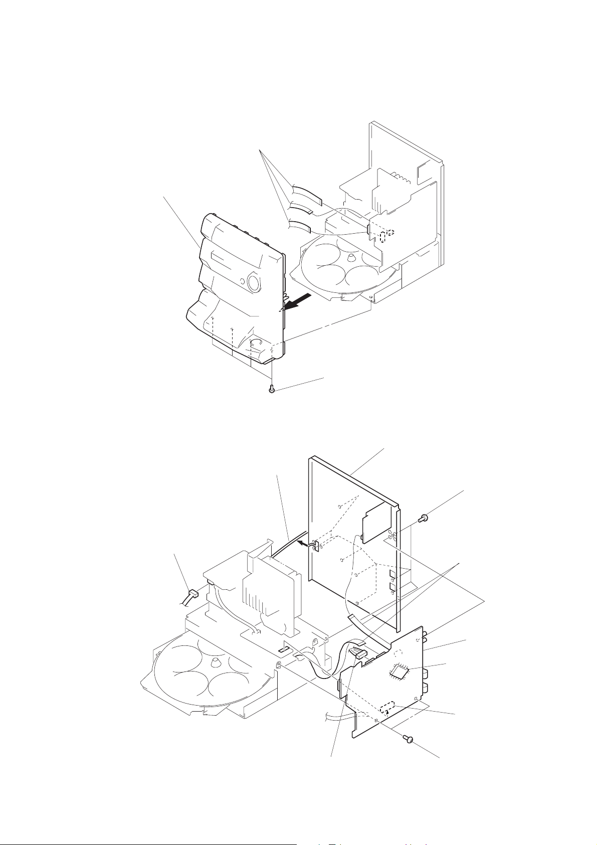
FRONT PANEL SECTION
3
front panel section
1
three frat wires
(CN102, 205, 206)
MAIN BOARD
3
connector
(CN901)
5
power cord
2
four screws
(BVTP 3
×
8)
6
back panel
IC201
4
ereven screws
(BVTP 3
1
two flat wires
(CN1, 202)
9
MAIN board
×
8)
2
connector
(CN203)
– 23 –
8
7
two screws
(BVTP 3
connector
(CN101)
×
8)
MAIN SECTION
3
two screws
(BVTP 3
2
connector
(CN203)
×
8)
1
flat wire (CN202)
4
main section
3
screw
(BVTP 3
3
two screws
(BVTP 3
×
8)
×
8)
CD MECHANISM DECK SECTION
3
4
CD mechanism
deck section
five screws
(BVTP 3
×
8)
2
flat wire
and lead wire
– 24 –
1
Open the clamp.
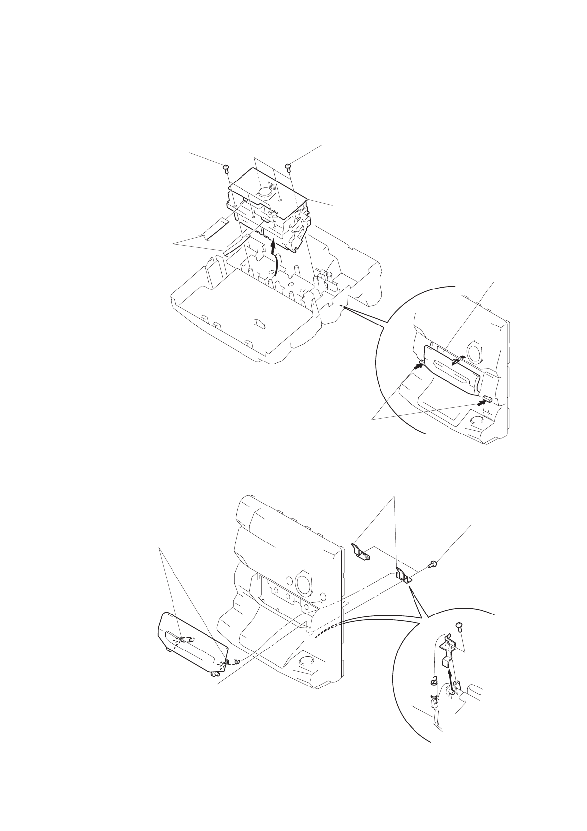
T APE MECHANISM DECK SECTION
4
three screws
(BVTP 2.6
3
two flat wires
(CN601, 1001)
×
8)
A
4
three screws
(BVTP 2.6
5
×
8)
Remove the tape mechanism
deck section to direction of the arrow
A
.
2
Open the
cassette lids.
CASSETTE LID ASS’Y
1
two springs
1
Push the
two buttons.
3
two bracket
2
two screws
(BVTP 2.6
×
8)
– 25 –
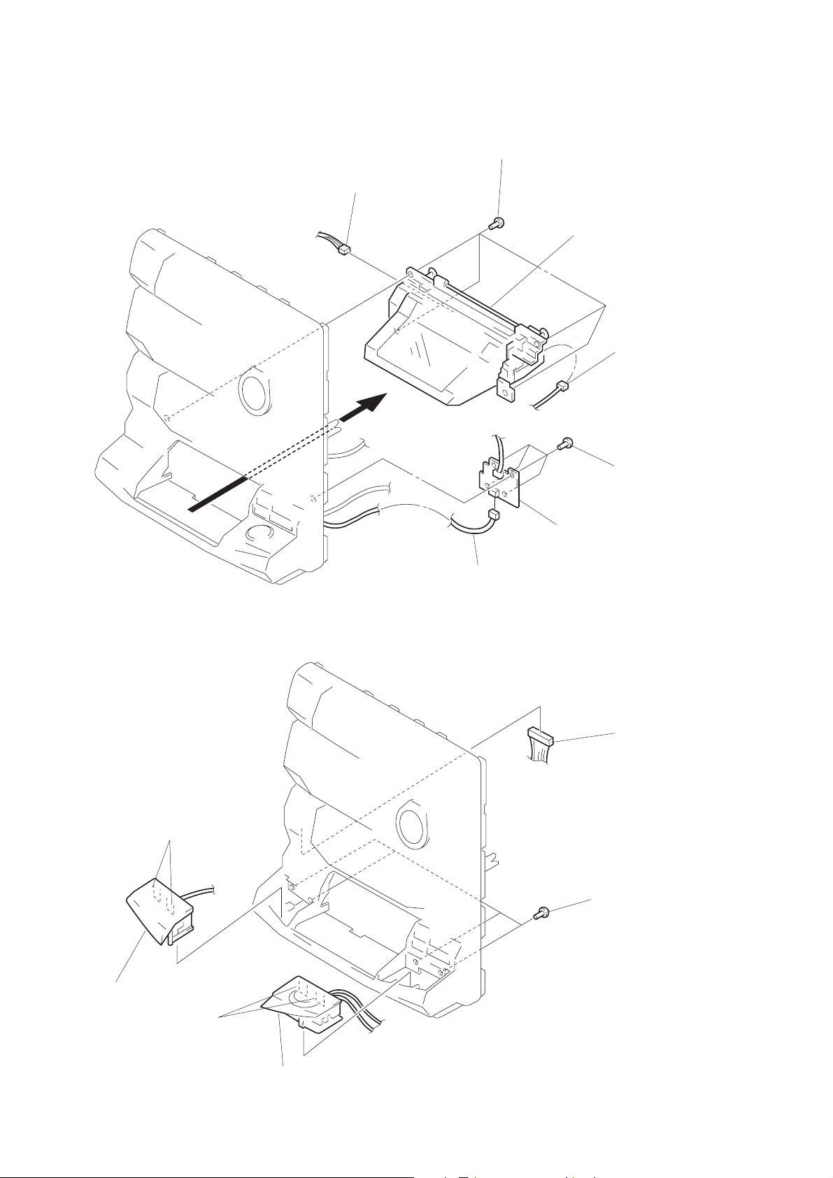
CD LID ASS’Y SECTION
5
connector
(CN671)
6
four screws
(BVTP 2.6
×
8)
7
CD lid ass’y
4
connector
(CN661)
2
four screws
(BVTP 2.6
×
8)
PANEL (A) / (B) SUB ASS’Y
3
two claws
1
connector
(CN642)
3
CD-B1 SW board
1
2
four screws
(BVTP 2.6
connector
(CN612)
×
8)
4
panel (A) sub ass’y
5
two claws
6
panel (B) sub ass’y
– 26 –
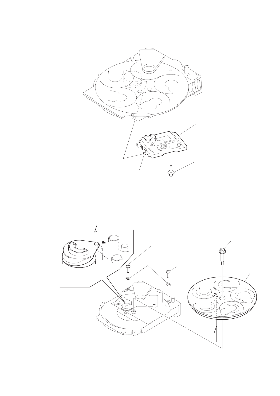
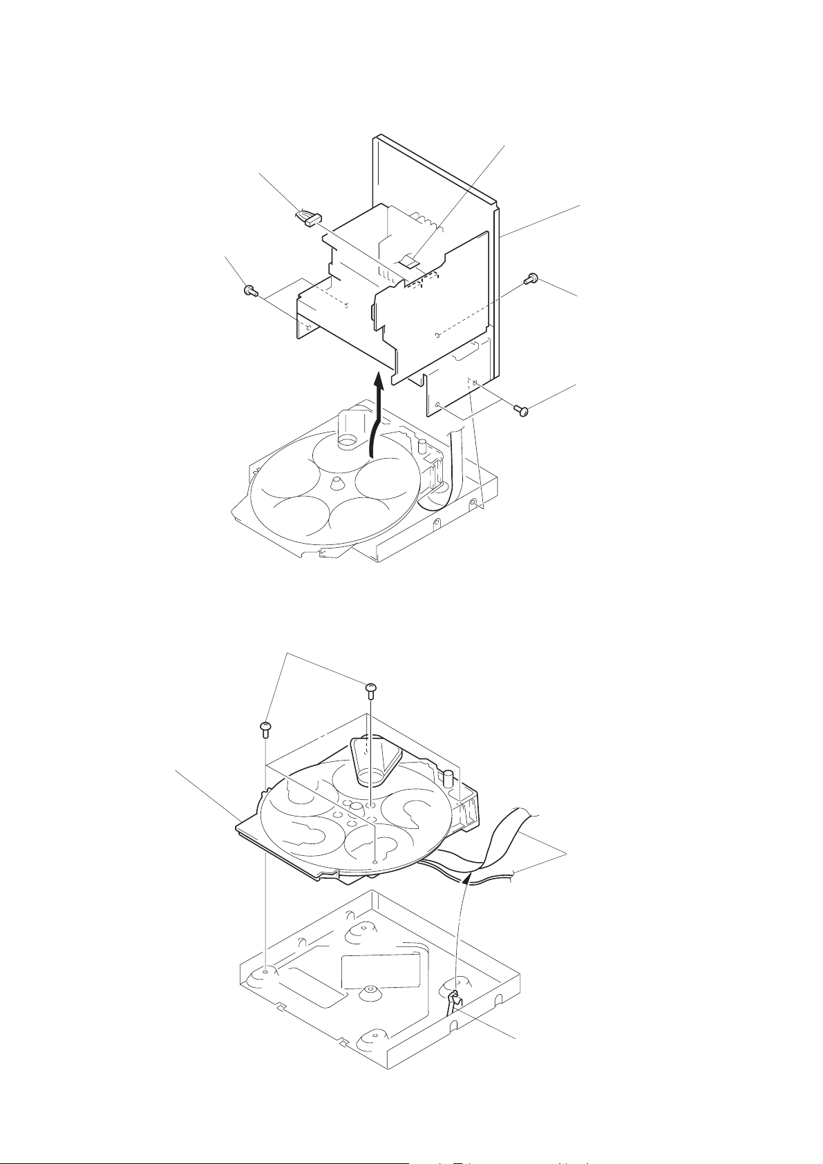
BASE UNIT
3
base unit
1
yoke bracket
DISC TABLE
Note:
When the disc table is installed, adjust the positions
of roller cam and mark z as shown in the figure, then
set to the groove of disc table.
A
2
boss
2
bracket (BU)
1
screw
(BVTP 3
×
8)
1
screw
(BVTP 3
3
step screw
×
8)
4
disc table
– 27 –
A
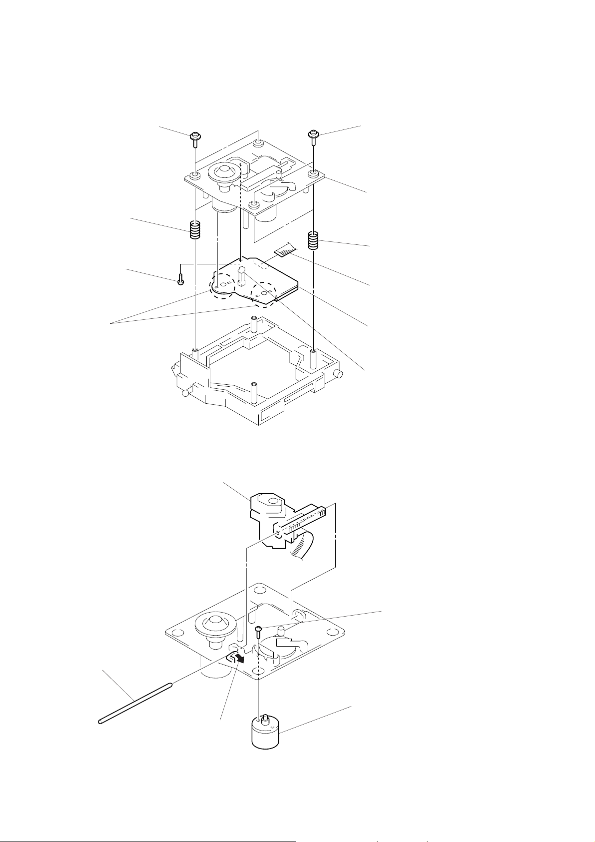
BD BOARD
3
5
screw
(BVTP 2.6
6
Removal
the four solders.
1
two screws
(PTPWH M2.6
two springs
×
8)
1
×
6)
two screws
(PTPWH M2.6
2
optical pick-up
section
3
two springs
4
flat wire
(CN101)
7
BD board
×
6)
OPTICAL PICK-UP, SLED MOTOR
3
optical pick-up
2
sled shaft
limit switch
4
two screws
(P2
×
3)
1
claw
– 28 –
5
sled motor
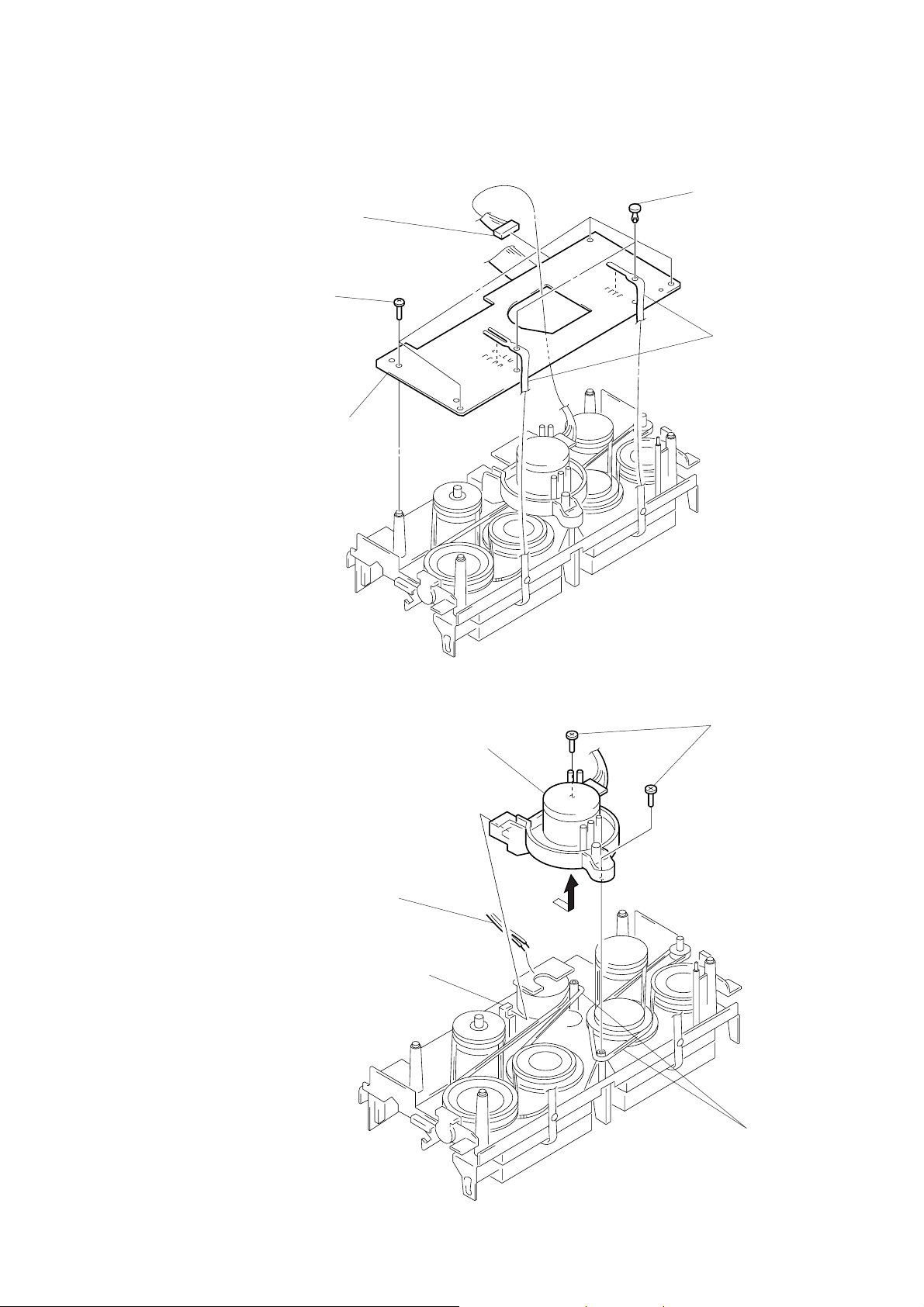
AUDIO BOARD
4
four screws
(BTP 2.6
1
connector
(CN651)
×
4)
5
MD board
2
two rivets
3
Break the soldering of two
flexible flat cables.
CAPSTAN MOTOR
4
1
Break the soldering of
motor lead.
Removal the capstan motor
to direction of the arrow.
3
claw
2
two screws
(BTP 2.6
5
Hang the
two belts.
×
8)
– 29 –

SECTION 3
TEST MODE
[MC Cold Reset]
• The cold reset clears all data including preset data stored in the
RAM to initial conditions. Execute this mode when returning
the set to the customer.
Procedure:
1. Press three buttons GROOVE , ENTER/NEXT , and
DISC 1 simultaneously.
2. The fluorescent indicator tube becomes blank instantaneously,
and the set is reset.
[CD Delivery Mode]
• This mode moves the pickup to the position durable to vibra-
tion. Use this mode when returning the set to the customer after
repair.
Procedure:
1. Press POWER button to turn the set ON.
2. Press PLAY MODE button and POWER button simulta-
neously.
3. A message “LOCK” is displayed on the fluorescent indicator
tube, and the CD delivery mode is set.
[MC Hot Reset]
• This mode resets the set with the preset data kept stored in the
memory. The hot reset mode functions same as if the power
cord is plugged in and out.
Procedure:
1. Press three buttons GROOVE , ENTER/NEXT , and
DISC 2 simultaneously.
2. The fluorescent indicator tube becomes blank instantaneously,
and the set is reset.
[Sled Servo Mode]
• This mode can run the CD sled motor freely. Use this mode, for
instance, when cleaning the pickup.
Procedure:
1. Select the function “CD”.
2. Press three buttons GROOVE , ENTER/NEXT , and
FLASH simultaneously.
3. The Sled Servo mode is selected, if “CD” is blanking on the
fluorescent indicator tube.
4. With the CD in stop status, press ) button in CD section
to move the pickup to outside track, or 0 button to inside
track.
5. To exit from this mode, perform as follows:
1) Move the pickup to the most inside track.
2) Press three buttons in the same manner as step 2.
Note:
• Always move the pickup to most inside track when exiting from
this mode. Otherwise, a disc will not be unloaded.
• Do not run the sled motor excessively, otherwise the gear can
be chipped.
[Change-over of AM T uner Step between 9kHz and 10kHz]
• A step of AM channels can be changed over between 9kHz and
10kHz.
Procedure:
1. Press POWER button to turn the set ON.
2. Select the function “TUNER”, and press TUNER/BAND
button to select the BAND “AM”.
3. Press POWER button to turn the set OFF.
4. Press ENTER/NEXT and POWER buttons simultaneously,
and the display of fluorescent indicator tube changes to “AM
9k STEP” or “AM 10k STEP”, and thus the channel step is
changed over.
[LED and Fluorescent Indicator Tube All Lit, Key Check
Mode]
Procedure:
1. Press three buttons GROO VE , ENTER/NEXT , and DISC 3
simultaneously.
2. LEDs and fluorescent indicator tube are all turned on.
Press DISC 2 button, and the key check mode is activated.
3. In the key check mode, the fluorescent indicator tube displays
“K 1 V0 J0”. Each time a button is pressed, “K”value increases. However , once a button is pressed, it is no longer taken
into account.
“J” Value increases like 1, 2, 3 ... if rotating JOG knob in “+”
direction, or it decreases like 0, 9, 8 ... if rotating in “–” direction.
“V” Value increases like 1, 2, 3 ... if rotating VOLUME knob
in “+” direction, or it decreases like 0, 9, 8 ... if rotating in “–
” direction.
4. To exit from this mode, press three buttons in the same manner as step 1, or disconnect the power cord.
[Change-over of FUNCTION Name]
• The FUNCTION name of external input terminal can be changed
over to VIDEO or MD. W ith the FUNCTION selected to “MD”,
about 5dB mute is applied to the input gain.
Procedure:
1. Press POWER button to turn the set OFF.
2. Press POWER button together with FUNCTION button, and
the power is turned on, the display of fluorescent indicator
tube changes to “MD” or “VIDEO” instantaneously, and thus
the FUNCTION is changed over.
– 30 –
Loading...