

Snorkel sn6013-15019 User Manual [en, de, es, fr]

Operator Manual
Manuel de l’utilisateur
Betriebsanleitung
Manual del operador
X-Series
X-Series
SERIAL NO. 6013 to Current
WARNING
All personnel shall carefully read, understand and follow all safety rules, and
operating instructions before performing maintenance on or operating any
UpRight aerial work platform.
Refer to page 2 for the english language version of this Operator Manual.
AVERTISSEMENT
Tout le personnel doit lire attentivement et respecter toutes les consignes de
sécurité avant d’entretenir ou d’utiliser une plate-forme élévatrice UpRight.
Réferez-vous à la page 10 pour la version en français de ce manuel de l’utilisateur.
ACHTUNG
Das Bedienungspersonal muß die Sicherheitsregeln und die Bedienungsanweisungen
lesen, verstehen und befolgen, bevor Wartungsarbeiten an einer UpRight Scheren-
Arbeitsbühne durchgeführt werden oder diese benutzt wird.
Siehe Seite 18 zwecks der deutschsprachigen Ausgabe dieser Betriebsanleitung.
ADVERTENCIA
Todo el personal debe leer atentamente, entender y respetar todas las reglas de
eguridad, las instrucciones de operación antes de efectuar trabajos de mantenimiento
o manejar cualquier plataforma aérea de trabajo UpRight.
Referirse a la página 26 para la versión en español de este manual del operador.
1
English Language Section
WARNING
All personnel shall carefully read, understand and follow all safety rules,
operating instructions and the before operating or performing maintenance on
any UpRight aerial work platform.
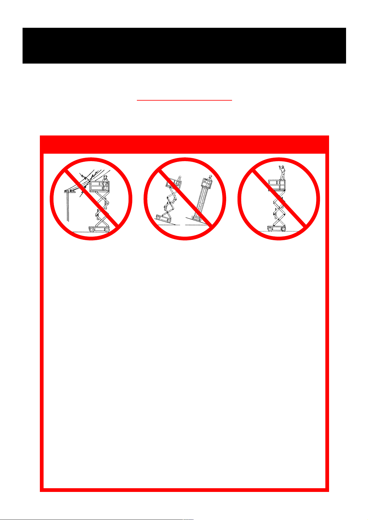
SAFETY RULES
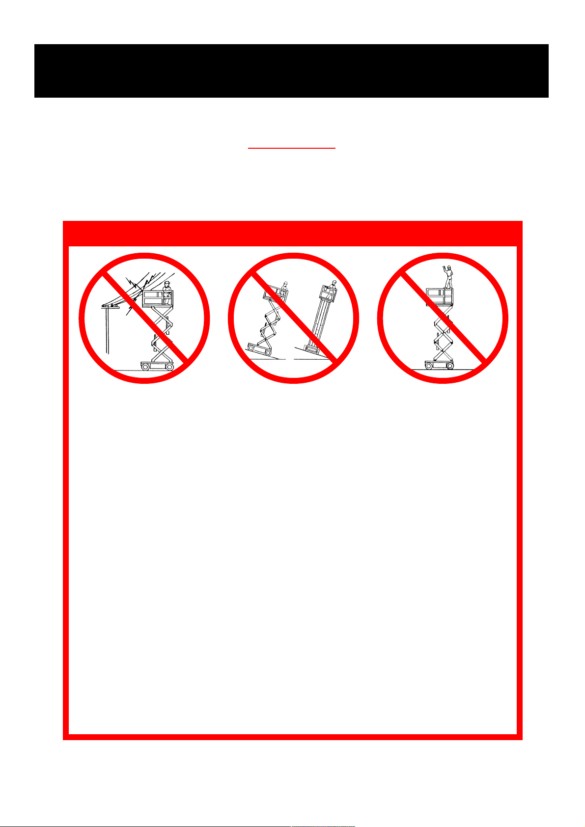
NEVER operate the machine
within ten feet of power lines.
THIS MACHINE IS NOT INSULATED.
NEVER operate the machine in noise levels above 80 dB.
NEVER operate the machine without first surveying the work area for surface hazards such as
holes, drop-offs, bumps and debris.
NEVER operate the machine if all guardrails are not properly in place and secured with all
fasteners properly torqued.
SECURE and lock gate after mounting platform.
NEVER use ladders or scaffolding on the platform.
NEVER attach overhanging loads or increase platform size.
LOOK up, down and around for overhead obstructions and electrical conductors.
DISTRIBUTE all loads evenly on the platform. See the back cover for maximum platform load.
NEVER use damaged equipment. (Contact UpRight for instructions. See toll-free phone number
on back cover.)
NEVER change operating or safety systems.
INSPECT the machine thoroughly for cracked welds, loose hardware, hydraulic leaks, damaged
control cable, loose wire connections and wheel bolts.
NEVER climb down elevating assembly with the platform elevated.
NEVER perform service on machine while platform is elevated without blocking elevating assembly.
NEVER recharge batteries near sparks or open flame; batteries that are being charged emit
highly explosive hydrogen gas.
AFTER USE secure the work platform against unauthorized use by turning the key switches off
and removing the keys.
NEVER replace any component or part with anything other than original UpRight replacement
parts without the manufacturers consent.
NEVER elevate the platform or
drive the machine while elevated unless the machine is
on firm level surface.
NEVER sit, stand or climb on
guardrail or midrail.
2
Introduction
This manual covers all european models of the X-Series Work
Platforms. This manual must be stored on the machine at all
times.
Pre-Operation and Safety
Inspection
Read, understand and follow all safety rules and operating instructions and then perform the following steps
each day before use.
1. Open modules and inspect for damage, oil leaks or missing parts.
2. Check the level of the hydraulic oil with the platform fully
lowered. Open the Left Module and remove the reservoir
cap, oil should be visible in the filler screen. Add ISO #46
hydraulic oil if necessary.
3. Check that fluid level in the batteries is correct
(See Battery Maintenance, Page 8).
4. Verify batteries are charged.
5. Check that A.C. extension cord has been disconnected
from charger.
6. Check that all guardrails are in place, the Slide out Deck
Extension is secured with the pin and all fasteners are
properly tightened.
7. Carefully inspect the entire work platform for damage
such as cracked welds or structural members, loose or
missing parts, oil leaks, damaged cables or hoses, loose
connections damaged or missing labels, and tire damage.
8. Move machine, if necessary, to unobstructed area to
allow for full elevation.
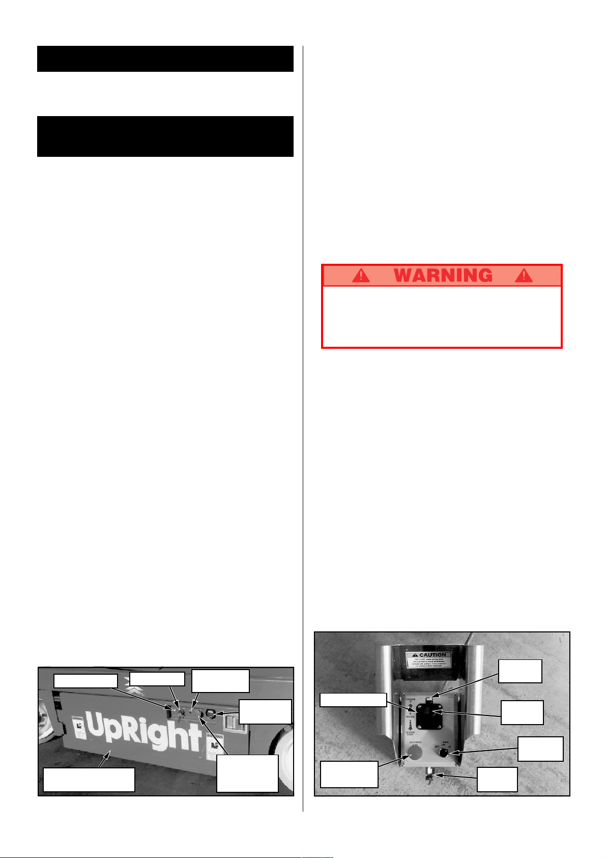
9. Turn Chassis and Platform Emergency Stop Switches ON
(Figure 1 & 2) by pulling the button out.
10. Turn the Chassis Key Switch (Figure 1) to CHASSIS.
11. Push Chassis Lift Switch (Figure 1) to UP position and
fully elevate platform.
12. Visually inspect the elevating assembly, lift cylinder, cables
and hoses for damage or erratic operation. Check for missing or loose parts.
13. Verify that the Pot Hole Protection Supports have rotated
into position under each module.
14. Partially lower the platform by pushing Chassis Lift
Switch to DOWN, and check operation of the audible
lowering alarm.
15. Open the Chassis Emergency Lowering Valve (Figure 3)
to check for proper operation by pulling and holding the
knob out. Once the platform is fully lowered, close the
valve by releasing the knob.
16. Turn the Chassis Key Switch to DECK.
17. Close and latch the module doors.
18. Check that route is clear of persons, obstructions, holes
and drop-offs, is level and capable of supporting the
wheel loads.
19. Turn the Controller Key Switch to ON.
20. Unhook Controller from guardrail. Firmly grasp Controller
while performing the following checks from the ground.
STAND CLEAR of the work platform while performing the following checks.
Protect control console cable from possible damage
while performing checks.
21. Pull Emergency Stop Button out to the ON position.
22. Position Function Switch to DRIVE. For 20W, 26, and 32
models, use both HI and LOW drive when performing
step 22.
23. Grasp the Control Lever so the Interlock Lever is depressed (releasing the Interlock Lever cuts power to
Controller), slowly position the Control Lever to FOR-
WARD then REVERSE to check for speed and directional
control. The farther you push or pull the Control Lever
from center the faster the machine will travel.
24. Push Steering Switch RIGHT then LEFT to check for
steering function.
25. Push in the Emergency Stop Switch Button.
26. Rehook Controller on side guardrail.
Control Fuse
Pot Hole Protection
Support
Figure 1: Chassis, Left Side
Key Switch
Chassis Lift
Switch
Chassis
Emergency
Stop Switch
Hourmeter
(Optional)
3
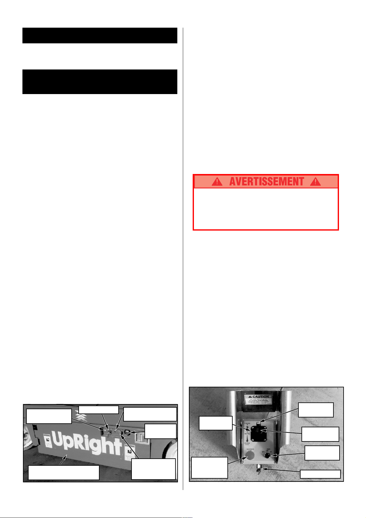
Control Lever
Emergency
Stop Switch
Interlock
Lever
Steering
Switch
Function
Switch
Key
Switch
Figure 2: Controller

Operation
Before operating work platform ensure that pre-operation
and safety inspection has been completed and any discrepancies have been corrected.
Travel With Platform Lowered
1. Check that route is clear of people, obstructions, holes
and drop-offs, is level and is capable of supporting wheel
loads.
2. Verify Chassis Key Switch is turned to DECK and Chassis Emergency Stop Switch is ON, pull button out.
3. After mounting platform, lower top rail across entrance and secure entryway closure. Check that guardrails are properly assembled, in position, and that the Slide Out Deck Extension is
secured with pin. Attach Controller to left or right guardrail.
4. Check clearances above, below and to the sides of platform.
5. Pull Controller Emergency Stop Button out to ON position. In case of emergency, push down to stop all functions.
6. Position Function Switch to DRIVE. For 20W, 26, and 32
models: position Function Switch to HI for traveling on
level ground, LOW when extra torque is required for
climbing ramps.
7. Grasp the Control Lever so the Interlock Lever is depressed (releasing the Interlock Lever cuts power to
Controller), slowly push or pull the Control Lever to FOR-
WARD or REVERSE position to travel in the desired
direction. The farther you push or pull the Control Lever
from center the faster the machine will travel.
Steering
1. Position Function Switch to DRIVE.
2. While holding the Control Lever so that the Interlock Lever is
depressed, push the Steering Switch to RIGHT or LEFT to turn
wheels in the desired direction. Observe the tires while maneuvering the work platform to ensure proper direction.
NOTE: Steering is not self-centering. Wheels must be
returned to straight ahead position by operating Steering
Switch.
Elevating Platform
1. Position Function Switch to LIFT.
2. While holding the Control Lever so that the Interlock Lever is
depressed, push Control Lever forward to UP, the farther
you push the Control Lever the faster the Platform will elevate.
3. If the machine is not level an Alarm will sound and the machine
will not lift or drive. If an Alarm sounds, immediately lower the
Platform and move the machine to a level location before
attempting to re-elevate the Platform.
Pot Hole Protection System
When the platform is elevated, the pot hole protection system will
automatically deploy. The pot hole protection system will retract
automatically when the platform is lowered, and high speed drive is
engaged.
Be aware that while the pot hole protection system is deployed, minimum ground clearance is reduced to
3
/4 inches.
Travel With Platform Elevated
NOTE: Work platform will travel at reduced speed when
platform is elevated.
1. Check that route is clear of persons, obstructions, holes
and drop-offs, is level and capable of supporting the
wheel loads.
2. Check clearances above, below and to the sides of platform.
3. Position Function Switch to DRIVE position.
4. Grasp the Control Lever so the Interlock Lever is depressed
(releasing the Interlock Lever cuts power to Controller), push
Control Lever to FORWARD or REVERSE for desired direction
of travel.
5. If the machine is not level an Alarm will sound and the machine
will not lift or drive. If an Alarm sounds, immediately lower the
Platform and move the machine to a level location before
attempting to re-elevate the Platform.
Lowering Platform
1. Position Function Switch to LIFT.
2. Grasp the Control Lever so the Interlock Lever is depressed, pull back on the Control Lever. A warning alarm
will sound when lowering and the machine will descend to
a predetermined height which will allow you to exit the
platform safely.
3. To close the scissors completely for passage through a
doorway: dismount the platform, check the elevating assembly to insure that no one is in contact with the machine, and
lower the platform fully by using the emergency lowering
valve (see Emergency Lowering, next page).
4
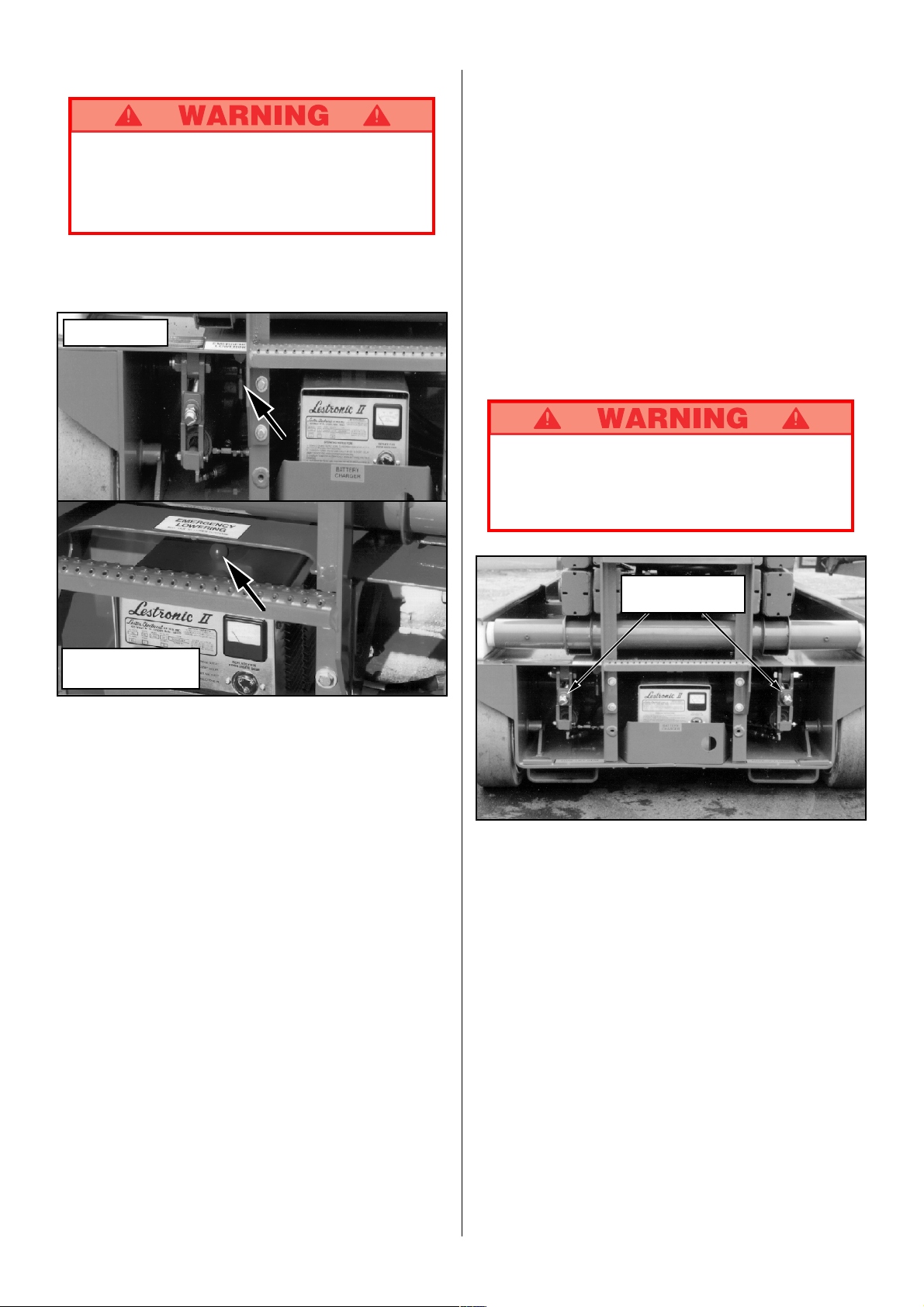
Emergency Lowering
If the platform should fail to lower, NEVER climb
down the elevating assembly.
Ask a person on the ground to open the Emergency
Lowering Valve located at the rear of the machine
(Figure 3).
1. Open the Emergency Lowering Valve by pulling on the
handle.
2. To close, release the handle.
X32N Model
Parking Brake Release (Figure 4)
Perform the following only when the machine will not operate
under its own power and it is necessary to move the machine or
when towing the machine up a grade or winching onto a trailer to
transport.
Note: X32N models have two identical brake adjustment
nuts located on both sides of the ladder.
The Brake Adjustment/Release Nut(s) is (are) located at the
rear of the machine to the right (and left) of the ladder.
1. To release the brakes turn the nut(s) counterclockwise until the
brakes disengage from the tires.
2. The machine will now roll when pushed or pulled.
3. To reset the brakes, turn the nut(s) clockwise until the
brakes have fully engaged the tires. Test the brakes on a
22% slope before returning the machine to service.
Never operate work platform with the Parking
Brakes released. Serious injury or damage could
result.
Never tow faster than 1 ft./sec. (.3m/sec.).
X20N, X20W, and
X26N Models
Figure 3: Emergency Lowering Valve Handle
Fold Down Guardrails
This procedure applies only to the X32N model for the
purpose of passing through a standard double doorway.
Guardrails must be returned to proper position before
operating the work platform.
Fold Down Procedure
1. Unhook the controller from the side guardrail and place
on the platform.
2. Unpin the front and rear upper rails from the side rails
and rotate inwards.
3. Starting with the rollout deck rails and then the outer rails, lift up
on each guardrail and fold inward.
Erection Procedure
1. Starting with the outer rails and then the rollout deck rails,
raise each guardrail and drop it down securing it in the
vertical position.
2. Rotate the front and rear upper rails outward and secure
them to the opposite side rails using the retaining pins.
3. Hang the controller on the side guardrail.
Parking Brake
Adjustment Nuts
Figure 4: Parking Brake Release (X32N Shown)
After Use Each Day
1. Ensure that the platform is fully lowered.
2. Park the machine on level ground, preferably under
cover, secure against vandals, children or unauthorized
operation.
3. Turn the Key Switches to OFF and remove the keys to
prevent unauthorized operation.
5
Transporting Work Platform
By Forklift
NOTE: Forklifting is for transporting only.
See specifications for weight of work platform and
be certain that forklift is of adequate capacity to lift
platform.
Forklift from the rear of the machine using the forklift pockets
provided. If necessary, the machine may be forklifted from the
side by lifting under the Chassis Modules.
Front Lifting
Points
Front Tie Down
Figure 6: Front Tie Downs, Lifting Lugs
By Crane
1. Secure straps to Chassis Lifting Lugs only (Figure 5 & 6).
By Truck
1. Maneuver the work platform into transport position and
chock wheels.
2. Secure the work platform to the transport vehicle with
chains or straps of adequate load capacity attached to
the chassis tie down lugs (Figures 5 & 6).
Front tie down lugs are not to be used to lift work
platform.
Overtightening of chains or straps through tie down
lugs may result in damage to work platform.
Maintenance
Never perform service on the work platform in the
Elevating Assembly area while platform is elevated
without first blocking the Elevating Assembly.
DO NOT stand in Elevating Assembly area while
installing or removing brace.
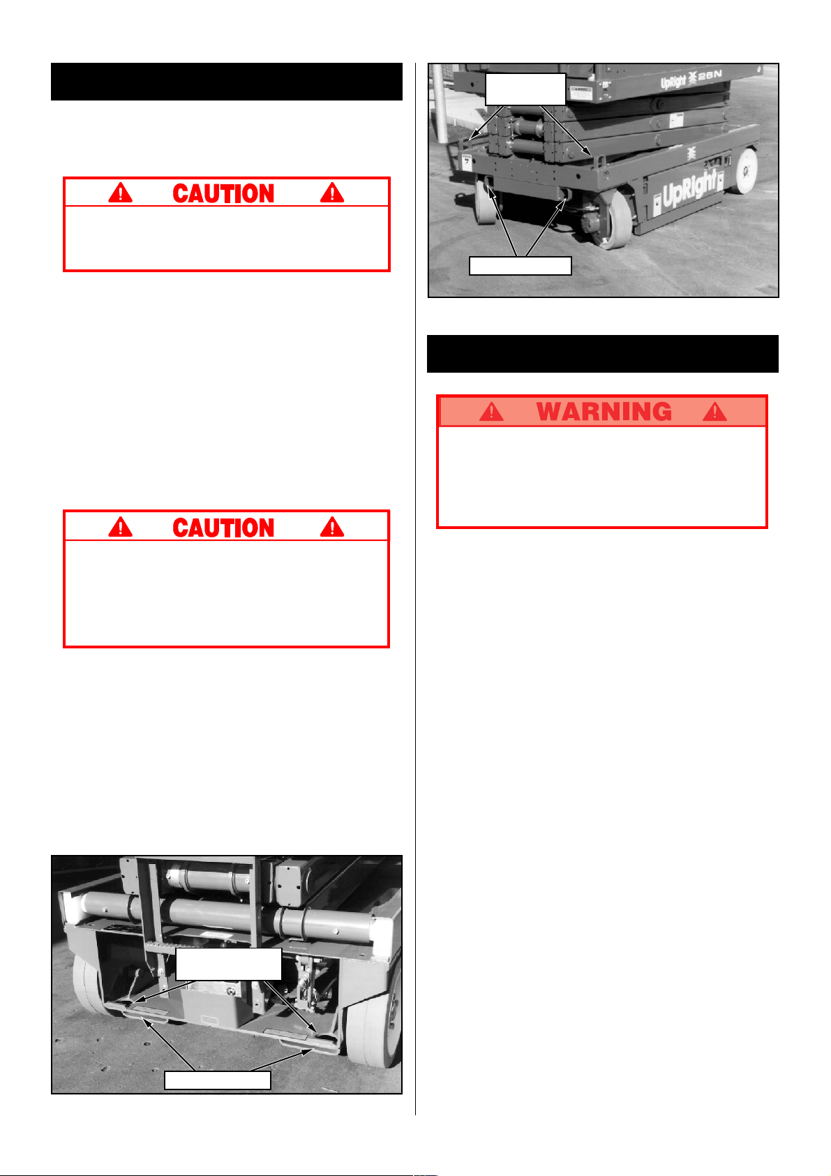
Blocking Elevating Assembly
(X20N, X20W, and X26N) See Figure 7
Installation
1. Park the work platform on firm level ground.
2. Verify both Emergency Stop Switches are ON.
3. Turn Chassis Key Switch to CHASSIS.
4. Position Chassis Lift Switch to UP and elevate platform
approximately nine (9) feet (2.7 m).
5. Rotate Scissors Brace towards the front and allow it to
hang vertical over the lower scissor pivot tube.
6. Push Chassis Lift Switch to DOWN position and gradually
lower platform until brace rests on lower scissor arm pivot
tube.
Rear Tie Down /
Lifting Points
Forklift Pockets
Figure 5: Rear Tie Downs, Lifting Points
Removal
1. Push Chassis Lift Switch to UP position and gradually
raise platform until the lower end of the Scissors Brace
will clear the lower scissor arm pivot tube.
2. Rotate Scissors Brace towards the rear so that it rests on
the cylinder mount, stowed position.
3. Push Chassis Lift Switch to DOWN position and completely lower platform.
Blocking Elevating Assembly (X32N)
6
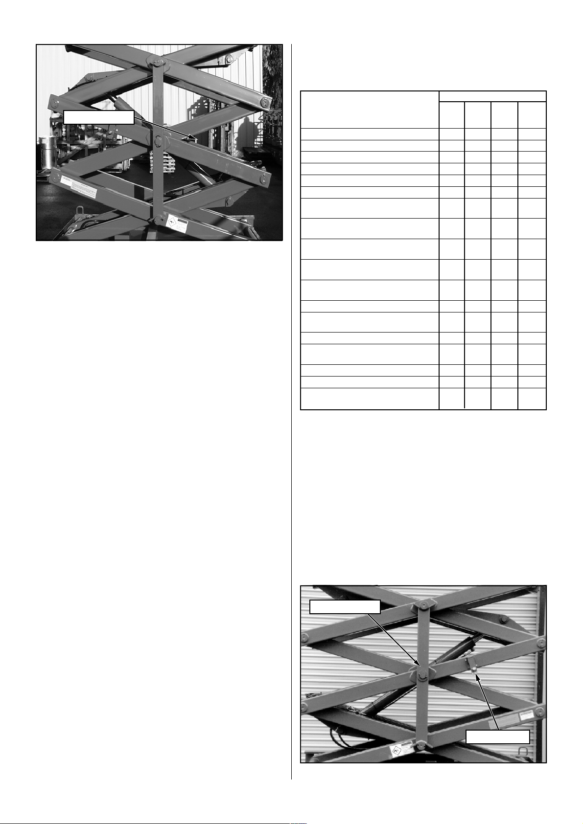
Scissors Brace
Figure 7: Blocking Elevating Assembly
(X20N, X20W, X26N)
See Figure 8
Installation
1. Park the work platform on firm level ground.
2. Verify both Emergency Stop Switches are ON.
3. Turn Chassis Key Switch to CHASSIS.
4. Position Chassis Lift Switch to UP and elevate platform
approximately nine (9) feet (2.7 m), leaving enough room
to freely rotate the Scissors Brace.
5. Pull out on the retaining pin and rotate the Scissors Brace
into vertical position.
6. Push Chassis Lift Switch to DOWN position and gradually
lower platform until the upper and lower pivot pins rest on
the Scissors Brace.
Routine Service
Use the following table as a guide for routine maintenance,
refer to the Service Manual for complete service instructions.
SERVICE OPERATION
Clean entire work platform X
Check battery fluid level X
Charge batteries X
Check tires for damage X
Check lug nuts/bolts X
Check hydraulic fluid level X
Check for peeling, faded or
missing labels & replace
Check deck and guardrail
fasteners for proper torque
Inspect elevating assembly
for bends or cracking
Check for & repair collision
damage
Check emergency lowering
valve operation
Check electric motor brushes X
Check pivot pin bolts for
proper torque
Change hydraulic filter X
Check all fasteners for
proper torque
Change hydraulic fluid X
Grease front spindle bearings X
Grease pot hole protection cylinder
rod end bearing
INTERVAL
Monthly 6 Months 2 Years
Daily or or or
50 Hrs. 250 Hrs. 1000 Hrs.
X
X
X
X
X
X
X
X
Removal
1. Push Chassis Lift Switch to UP position and gradually
raise platform until the Scissors Brace will clear the pivot
pins.
2. Rotate the Scissors Brace counterclockwise until it locks
into position parallel with the scissor arm.
3. Push Chassis Lift Switch to DOWN position and completely lower platform.
Scissors Brace
Retaining Pin
Figure 8: Blocking Elevating Assembly (X32N)
7
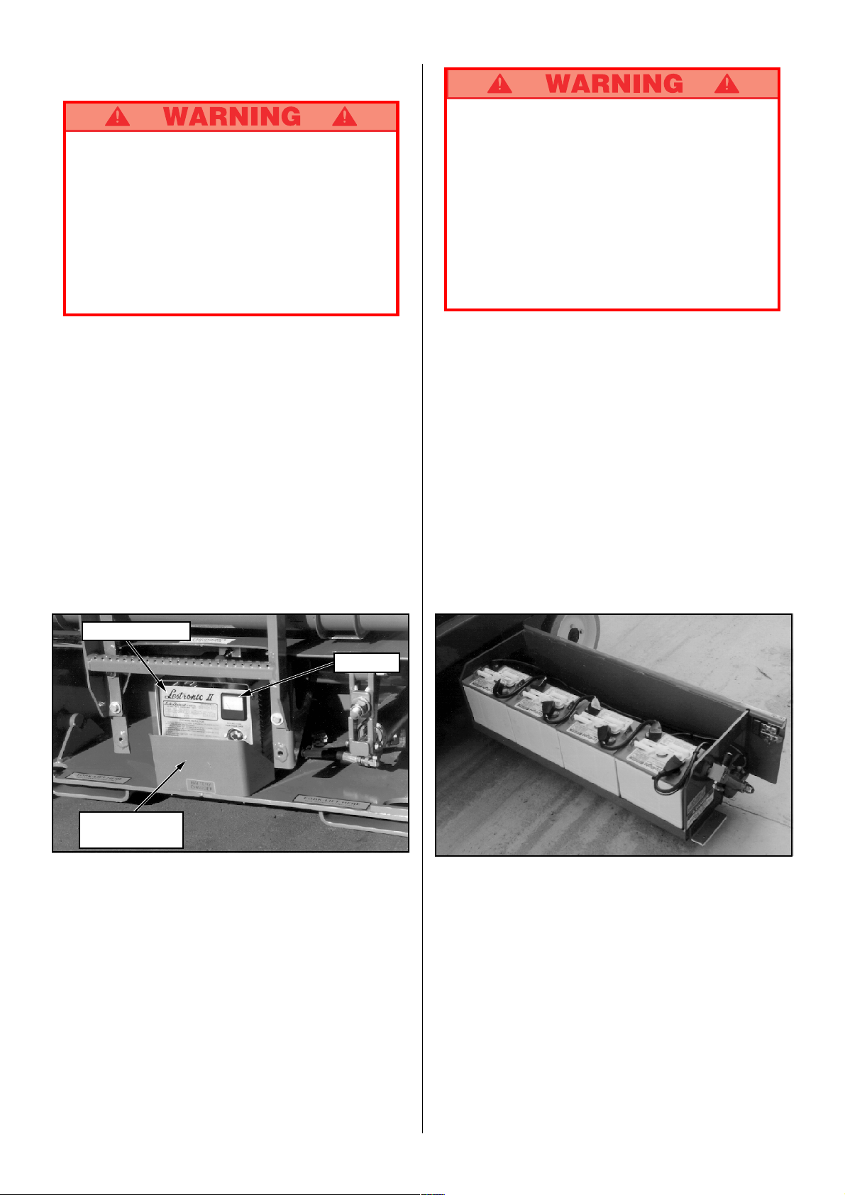
Battery Maintenance
Hazard of explosive gas mixture. Keep sparks,
flame and smoking materials away from batteries.
Always wear safety glasses when working with
batteries.
Battery fluid is highly corrosive. Rinse away any
spilled fluid thoroughly with clean water.
Always replace batteries with UpRight batteries or
manufacturer approved replacements weighing 62
lbs. each.
Charge batteries in a well ventilated area.
Do not charge batteries when the work platform is
in an area containing sparks or flames.
Permanent damage to batteries will result if batter-
ies are not immediately recharged after discharging.
Never leave charger operating unattended for more
than two days.
Never disconnect cables from batteries when
charger is operating.
Keep charger dry.
Check battery fluid level daily, especially if work platform is
being used in a warm, dry climate.
If electrolyte level is lower than 3/8 in. above plates add
distilled water only. DO NOT use tap water with high mineral
content it will shorten battery life.
Keep terminals and tops of batteries clean.
Refer to the Service Manual to extend battery life and for
complete service instructions.
Battery Charging
Charge batteries at end of each work shift or sooner if
batteries have been discharged.
Battery Charger
Ammeter
1. Check battery fluid level. If electrolyte level is lower than
3/8 in. (10 mm) above plates add distilled water only.
2. Connect extension cord (12 gauge (1.5 mm²) conductor
minimum and 50 ft. (15 m) in length maximum) to the
charger outlet plug located at the rear of the machine.
Connect other end of extension cord to properly
grounded outlet of proper voltage and frequency.
3. Charger turns on automatically after a short delay, the
ammeter will indicate DC charging current.
4. Charger turns off automatically when batteries are fully
charged.
Charger Plug
(Behind Guard)
Figure 9: Battery Charger
Figure 10: Battery Module
8

SPECIFICATIONS*
ITEM X20N X20W X26N X32N
Platform Size 28 in x 87 in [711 mm x 2.21 m] 44 in. x 87 in. [1.12 m x 2.21 m ] 44 in. x 87 in. [1.12 m x 2.21 m] 44 in. x 87 in. [1.12 m x 2.21 m]
w/ Extension Inside Toeboards Inside Toeboards Inside Toeboards Inside Toeboards
Max. Platform Capacity
Standard w/ Extension 750 lbs. [340kg] 1000 lbs. [453 kg] 1000 lbs. [453 kg] 750 lbs. [340 kg]
on Extension 250 lbs. [110 kg] 250 lbs. [110 kg] 250 lbs. [110 kg] 250 lbs. [110 kg]
Max. No. of occupants
Standard 3 people 4 people 4 people 3 people
on Extension 1 person 1 person 1 person 1 person
Height
Working Height 26 ft. [7.9 m] 26 ft. [7.9 m] 32 ft. [9.75 m] 38 ft. [11.58 m]
Max. Platform Height 20 ft. [6.1 m] 20 ft. [6.1 m] 26 ft. [7.92 m] 32 ft. [9.75 m]
Min. Platform Height 38 in. [.97 m] 39 in. [.99 m] 43 in. [1.09 m] 43 in. [1.09 m]
Dimensions
Weight 3,828 lbs. [1656 kg] 4,273 lbs. [1858 kg] 4,747 lbs. [2072 kg] 5,180 lbs. [2643 kg]
Overall Width 32 1/2 in. [.83 m] 48 in. [1.22 m] 48 in. [1.22 m] 48 in. [1.22 m]
Overall Height 78 in. [1.98 m] 79 in. [2.0 m] 83 in. [2.11 m] 83 in. [2.11 m]
Overall Length 92 in. [2.34 m] 92 in. [2.34 m] 92 in. [2.34 m] 92 in. [2.34 m]
Driveable Height 20 ft. [6.1 m] 20 ft. [6.1 m] 26 ft. [7.93 m] 32 ft. [9.75 m]
Surface Speed
Platform Lowered 0 to 2.3 mph [0 to 3.70 km/h] 0 to 2.3 mph [0 to 3.70 km/h] 0 to 2.3 mph [0 to 3.70 km/h] 0 to 2.3 mph [0 to 3.70 km/h]
Platform Raised 0 to .7 mph [0 to 1.13 km/h] 0 to .7 mph [0 to 1.13 km/h] 0 to .7 mph [0 to 1.13 km/h] 0 to .7 mph [0 to 1.13 km/h]
Energy Source 24 Volt Battery Pack (4-220 Amp 24 Volt Battery Pack (4-220 Amp 24 Volt Battery Pack (4-220 Amp 24 Volt Battery Pack (4-220 Amp
System Voltage 24 Volt DC 24 Volt DC 24 Volt DC 24 Volt DC
Battery Charger 25 AMP, 60 Hz 110 VAC 25 AMP, 60 Hz 110 VAC 25 AMP, 60 Hz 110 VAC 25 AMP, 60 Hz 110 VAC
Battery Duty Cycle 25% for 8 Hours 25% for 8 Hours 25% for 8 Hours 25% for 8 Hours
Hydraulic Tank Capacity 4 Gallons [15.2 l] 4 Gallons [15.2 l] 4 Gallons [15.2 l] 5 Gallons [19 l]
Maximum Hydraulic
System Pressure 2400 psi [165 Bar] 2600 psi [179 Bar] 2600 psi [179 Bar] 2000 psi [137 Bar]
Lift System Three stage scissor assembly Three stage scissor assembly Four stage scissor assembly Five stage scissor assembly
Control System Smooth one hand joystick with Smooth one hand joystick with Smooth one hand joystick with Smooth one hand joystick with
Drive System Dual Front Wheel Hydraulic Dual Front Wheel Hydraulic Motors Dual Front Wheel Hydraulic Motors Dual Front Wheel Hydraulic Motors
Tires 15 in. [381 mm] Diameter Solid 15 in. [381 mm] Diameter Solid 15 in. [381 mm] Diameter Solid 15 in. [381 mm] Diameter Solid
Parking Brake Spring Applied, Hydraulic Release Spring Applied, Hydraulic Release Spring Applied, Hydraulic Release Spring Applied, Hydraulic Release
Turning Radius 8 in. [254 mm] Inside 8 in. [254 mm] Inside 8 in. [254 mm] Inside 8 in. [254 mm] Inside
Maximum Gradeability 23% [13 degrees] 23% [13 degrees] 22% [12 degrees] 22% [12 degrees]
Wheel Base 74 3/4 in. [1.9 m] 74 3/4 in. [1.9 m] 74 3/4 in. [1.9 m] 74 3/4 in. [1.9 m]
Guardrails 40 in. [1.02 m] 40 in. [1.02 m] 40 in. [1.02 m] 40 in. [1.02 m]
Toeboard 6 in. [152 mm] High 6 in. [152 mm] High 6 in. [152 mm] High 6 in. [152 mm] High
Hour, 6 Volt Batteires, min. wt. Hour, 6 Volt Batteires, min. wt. Hour, 6 Volt Batteires, min. wt. Hour, 6 Volt Batteires, min. wt.
62 lbs. each [28.12 kg]), 4 HP 62 lbs. each [28.12 kg]), 4 HP 62 lbs. each [28.12 kg]), 4 HP 62 lbs. each [28.12 kg]), 4 HP
DC Electric Motor DC Electric Motor DC Electric Motor DC Electric Motor
actuated by one Single Stage actuated by one Single Stage actuated by one Single Stage actuated by one Single Stage
Lift Cylinder Lift Cylinder Lift Cylinder Lift Cylinder
two speed operation two speed operation two speed operation two speed operation
Motors with series operation with series or parallel operation with series or parallel operation with series or parallel operation
Rubber, non-marking Rubber, non-marking Rubber, non-marking Rubber, non-marking
Brake with Manual Release Brake with Manual Release Brake with Manual Release Brake with Manual Release
* Specifications subject to change without notice.
Refer to Service Manual for complete parts and service
information.
9
Version française
AVERTISSEMENT
Tout le personnel doit lire attentivement et respecter toutes les consignes de sécurité et les
directives d’utilisation avant d’entretenir ou d’utiliser une plate-forme élévatrice UpRight.
RÈGLES DE SÉCURITÉ
NE JAMAIS utiliser la machine à
moins de 3 mètres (10 pieds) de
lignes d’énergie électriques.
CETTE MACHINE N’EST PAS
ISOLÉE.
NE JAMAIS utiliser la machine dans un environnement où le niveau de bruit dépasse 80 dB.
NE JAMAIS utiliser la machine sans avoir d’abord vérifié si la surface de la zone de travail ne présente pas de
dangers, tels que des trous, des dénivellations, des bosses et des débris.
NE JAMAIS utiliser la machine sans que tous les garde-corps soient bien montés en place et fixés solidement
au moyen de toutes les pièces de fixation serrées au bon couple.
REFERMER et verrouiller le portillon après être monté sur la plate-forme.
NE JAMAIS dresser d’échelle ni d’échafaudage sur la plate-forme.
NE JAMAIS agrandir la surface de la plate-forme, ni y fixer une charge qui la déborde.
REGARDER en haut, en bas et tout autour de la machine afin de s’assurer qu’il n’y a aucun conducteur électrique
ou autre obstacle aux alentours.
RÉPARTIR également toutes les charges sur la plate-forme. Pour connaître la capacité maximale de cette
dernière, voir la fiche technique à la page couverture arrière.
NE JAMAIS utiliser une machine endommagée. (Si la machine est endommagée, communiquer avec UpRight
en composant le numéro sans frais inscrit à la page couverture arrière.)
NE JAMAIS modifier les éléments assurant le fonctionnement de la machine, ni les dispositifs de sécurité.
VÉRIFIER la machine à fond afin en s’assurant que toutes les soudures et tous les câbles électriques ou de
commande sont en bon état, que toutes les pièces de fixation sont bien serrées, y compris les boulons de fixation
des roues, que le circuit hydraulique ne présente aucune fuite et que tous les fils électriques sont bien branchés.
NE JAMAIS descendre par le dispositif d’élévation lorsque la plate-forme est élevée.
NE JAMAIS effectuer des travaux d’entretien dans la zone du dispositif d’élévation d’une plate-forme élevée sans
avoir d’abord bloqué ce dernier au moyen d’un étai.
NE JAMAIS recharger la batterie d’accumulateurs près d’une flamme ou d’une source d’étincelles : au moment
du rechargement, les batteries dégagent de l’hydrogène gazeux hautement explosif.
APRÈS AVOIR UTILISÉ la plate-forme élévatrice, tourner la clé de l’interrupteur à la position d’arrêt (« OFF »),
puis la retirer afin de prévenir l’utilisation de la plate-forme par toute personne non autorisée.
NE JAMAIS remplacer quelque élément ou quelque pièce que ce soit par autre chose qu’une pièce d’origine
UpRight sans le consentement écrit du fabricant.
NE JAMAIS élever la plate-forme
sans que la machine ne soit sur
une surface horizontale solide et,
lorsque la plate-forme est élevée,
NE déplacer la machine QUE sur
une telle surface.
NE JAMAIS s’asseoir, monter ou
se mettre debout sur les rampes
du garde-corps de la plate-forme.
10
Introduction
Ce manuel couvre tous les modèles européens des plateformes élévatrices de la série X. Ce manuel doit être rangé en
permanence sur la machine.
Vérification préliminaire
de sécurité
Lire attentivement et respecter toutes les consignes de
sécurité et toutes les instructions de fonctionnement,
puis effectuer la procédure suivante tous les jours avant
l’emploi.
1. Ouvrir les modules et rechercher les détériorations, les
fuites d’huile et les pièces manquantes.
2. Vérifier le niveau de l’huile hydraulique avec la plateforme complètement abaissée. Ouvrir le module de
gauche et retirer le bouchon de réservoir, l’huile doit être
visible dans le filtre de remplissage. Ajouter de l’huile
hydraulique ISO nº 46 si besoin est.
3. Vérifier que le niveau de fluide des batteries soit correct.
(Voir entretien de la batterie, page 16).
4. Vérifier que les batteries soient chargées.
5. Vérifier que la rallonge d’alimentation alternative ait été
débranchée du chargeur.
6. Vérifier que tous les garde-corps soient en place, que
l’extension coulissante de plancher soit bloquée par la
goupille et que toutes les vis soient correctement
serrées.
7. Inspecter soigneusement la plate-forme élévatrice entière
en recherchant les détériorations telles que des soudures
ou des poutres structurelles fissurées, des pièces
manquantes ou desserrées, des fuites d’huile, des câbles
ou des flexibles endommagés, des connecteurs
desserrés et des détériorations des pneus.
8. Déplacer la machine, si besoin est, jusqu’à une zone
sans obstacle qui permette une extension complète.
9. Régler les boutons d’arrêt d’urgence du châssis et de la
plate-forme sur « ON » (Figures 1 et 2) en tirant sur le
bouton pour le faire sortir.
10. Mettre la clé de contact du châssis (Figure 1) sur
CHÂSSIS (« CHASSIS »).
11. Mettre le commutateur de levage du châssis (Figure 1)
en position HAUT (« UP ») et élever complètement la
plate-forme.
12. Inspecter visuellement l’ensemble de levage, le vérin de
levage, les câbles et les flexibles pour identifier les
détériorations et les fonctionnements aléatoires.
Rechercher les pièces manquantes ou desserrées.
13. Vérifier que les supports de protection contre les nids de
poule soient tournés en position sous chaque module.
14. Abaisser partiellement la plate-forme en poussant le
commutateur de levage du châssis vers BAS (« DOWN »)
et en vérifiant le fonctionnement de l’alarme sonore de
descente.
15. Ouvrir la vanne d’abaissement d’urgence du châssis (Figure 3) pour vérifier son bon fonctionnement en tirant la
poignée et en la maintenant sortie. Une fois la plate-forme
complètement abaissée, fermer la vanne en relâchant la
poignée.
16. Tourner la clé de contact du châssis sur PLATEAU («
DECK »).
17. Fermer et verrouiller les portes des modules.
18. Vérifier que le passage soit dégagé de personnes, obstacles, trous et pentes, qu’il soit horizontal et capable de
supporter la charge des roues.
19. Tourner la clé de contact du contrôleur sur « ON ».
20. Décrocher le contrôleur du garde-corps. Tenir fermement
le contrôleur tout en effectuant les contrôles suivants
depuis le sol.
RESTER ÉLOIGNÉ de la plate-forme pendant le
déroulement des contrôles suivants.
Protéger le câble de la console de commande
contre les détériorations éventuelles pendant
l’exécution des contrôles.
21. Tirer le bouton d’arrêt d’urgence en position « ON ».
22. Positionner le commutateur de fonction sur MARCHE («
DRIVE »). Dans le cas des modèles 20W, 26 et 32,
utiliser à la fois la marche « HI » et la marche « LOW»
pour exécuter l’étape 22.
23. Saisir le levier de commande de sorte que le levier de
verrouillage soit enfoncé (relâcher le levier de
verrouillage coupe l’alimentation du contrôleur),
positionner doucement le levier de commande en marche
AVANT (« FORWARD ») puis en marche ARRIÈRE («
REVERSE ») pour vérifier le contrôle de vitesse et de
direction. Plus vous poussez ou tirez le levier de
commande loin du centre, plus la machine se déplace
rapidement.
24. Pousser le contacteur de direction vers la droite (« RIGHT
»), puis vers la gauche (« LEFT ») pour vérifier le
fonctionnement de la direction.
25. Pousser le bouton de commutateur d’arrêt d’urgence.
26. Raccrocher le contrôleur sur le garde-corps latéral.
Fusible de circuit
de commande
Support de protection contre
les nids de poule
Clé de contact
Figure 1 : Châssis, côté gauche Figure 2 : Contrôleur
Commutateur de
levage du châssis
Horomètre
(option)
Commutateur
d’arrêt d’urgence
du châssis
Commutateur
11
Levier de
commande
d’arrêt
d’urgence
Levier de
verrouillage
Commutateur
de direction
Commutateur
de fonction
Clé de contact
 Loading...