

Page 1
kÉï=~ë=çÑW==
MRKOMNO
pfkfrp=L=pfkfrp=`p
lйЙк~нбеЦ=fелнкмЕнбзел
SINIUS / SINIUS CS Operating Instructions
bеЦдблЬ
Page 2

Page 3

Sirona Dental Systems GmbH
Operating Instructions SINIUS / SINIUS CS
Table of contents
1
2
General information................................................................................................. 11
1.1 Dear Customer, ............................................................................................ 11
1.2 Contact information ...................................................................................... 11
1.3 Notes on these Operating Instructions ......................................................... 12
1.3.1 General information on the Operating Instructions ........................... 12
1.3.2 Scope of these Operating Instructions.............................................. 12
1.4 Other valid documents ................................................................................. 13
1.5 Warranty and liability .................................................................................... 13
1.6 Intended use................................................................................................. 13
1.7 Formats and symbols used .......................................................................... 14
Safety instructions ................................................................................................... 15
bеЦдблЬ
2.1 Identification of the danger levels................................................................. 15
2.2 Information on the unit.................................................................................. 15
2.3 On-site installation........................................................................................ 15
2.4 Media quality ................................................................................................ 16
2.5 Connection to the public drinking water system ........................................... 16
2.6 Maintenance and repair................................................................................ 16
2.7 Trouble-free operation.................................................................................. 17
2.8 Vacuum system............................................................................................ 17
2.9 Patient chair ................................................................................................. 17
2.10 Ventilation slots ............................................................................................ 18
2.11 Intermittent operation ................................................................................... 18
2.12 Touchscreen................................................................................................. 18
2.13 Care and cleaning agents ............................................................................ 18
2.14 Modifications and extensions of the system................................................. 18
2.15 Electromagnetic compatibility....................................................................... 19
2.16 Electrostatic discharge ................................................................................. 19
2.17 Dismantling/Installation ................................................................................ 21
63 22 726 D3561
D3561.201.01.03.02 05.2012
3
Page 4

Sirona Dental Systems GmbH
Operating Instructions SINIUS / SINIUS CS
3
Unit description......................................................................................................... 22
3.1 Standards/Approvals..................................................................................... 22
3.2 Technical data............................................................................................... 24
3.3 System overview ........................................................................................... 26
3.4 Patient chair .................................................................................................. 28
3.5 Headrest........................................................................................................ 29
3.5.1 Motor-driven headrest........................................................................ 29
3.5.2 Double-jointed headrest..................................................................... 30
3.6 Foot control ................................................................................................... 31
3.7 Dentist element ............................................................................................. 32
3.7.1 Instrument positions........................................................................... 34
3.7.2 EasyTouch user interface .................................................................. 35
3.7.3 Touchscreen ...................................................................................... 36
3.7.4 Fixed keys on the dentist element...................................................... 37
3.8 Assistant element.......................................................................................... 39
3.8.1 Instrument positions........................................................................... 39
3.8.2 User interface..................................................................................... 40
3.8.3 Fixed keys on the assistant element.................................................. 40
3.9 Water unit...................................................................................................... 41
3.10 Outlet for add-on devices .............................................................................. 43
4
Operation.................................................................................................................. 45
4.1 Starting up the treatment center.................................................................... 45
4.1.1 Initial startup....................................................................................... 45
4.1.2 Switching the treatment center on/off................................................. 45
4.1.2.1 Power switch ....................................................................... 45
4.1.2.2 Main switch ......................................................................... 46
4.1.3 Selecting a user profile....................................................................... 46
4.2 Control concept of touchscreen .................................................................... 48
4.2.1 Virtual function keys........................................................................... 48
4.2.2 Instrument functions in the Start program.......................................... 49
4.2.3 Sub-screens and settings screens..................................................... 52
4.2.4 Footer................................................................................................. 52
63 22 726 D3561
4 D3561.201.01.03.02 05.2012
Page 5

Sirona Dental Systems GmbH
Operating Instructions SINIUS / SINIUS CS
4.3 Foot control .................................................................................................. 54
4.3.1 Wireless foot control.......................................................................... 54
4.3.1.1 Setting the wireless foot control on the treatment center ... 54
4.3.1.2 Battery voltage message.................................................... 54
4.3.2 Operating the foot control.................................................................. 54
4.3.3 Using the cursor control .................................................................... 56
4.3.3.1 Functionality ....................................................................... 56
4.3.3.2 Operating the cursor control............................................... 58
4.4 Patient chair ................................................................................................. 60
4.4.1 Safety instructions............................................................................. 60
4.4.2 Safety stop ........................................................................................ 61
4.4.3 Triggering an immediate movement stop.......................................... 62
4.4.4 Armrests............................................................................................ 63
4.4.5 Adjusting the motor-driven headrest ................................................. 64
4.4.5.1 Moving the headrest in/out................................................. 64
4.4.5.2 Inclining the headrest ......................................................... 65
4.4.6 Adjusting the double-jointed headrest............................................... 66
4.4.7 Moving the patient chair via chair programs ..................................... 67
4.4.7.1 Moving the patient chair to the entry/exit position .............. 67
4.4.7.2 Moving the patient chair to the mouth rinsing position ....... 68
4.4.7.3 Using the last position memory function............................. 69
4.4.7.4 Activating other chair programs.......................................... 69
4.4.8 Moving the chair manually ................................................................ 70
4.4.8.1 Open manual chair setting screen...................................... 70
4.4.8.2 Tilting the patient couch ..................................................... 71
4.4.8.3 Adjusting the chair height................................................... 71
4.4.9 Creating chair and shock positioning programs ................................ 72
4.4.10 Setting the active lumbar support...................................................... 73
bеЦдблЬ
4.5 Dentist element ............................................................................................ 74
4.5.1 Maximum load capacity..................................................................... 74
4.5.2 Height adjustment ............................................................................. 74
4.5.3 Positioning the dentist element ......................................................... 74
4.5.4 Fixed keys on the dentist element..................................................... 76
63 22 726 D3561
D3561.201.01.03.02 05.2012
4.5.4.1 Main switch......................................................................... 76
4.5.4.2 Program change keys ........................................................ 76
4.5.4.3 Timer function..................................................................... 77
4.5.4.4 Shock positioning ............................................................... 78
4.5.4.5 Operating light.................................................................... 78
5
Page 6

Sirona Dental Systems GmbH
Operating Instructions SINIUS / SINIUS CS
4.5.4.6 Composite function ............................................................. 79
4.5.4.7 Tumbler filling...................................................................... 79
4.5.4.8 Flushing of the cuspidor bowl.............................................. 80
4.5.4.9 Freely selectable function ................................................... 81
4.5.4.10 Clean................................................................................... 81
4.5.4.11 Setup................................................................................... 81
4.5.5 Quick setting keys and function levels ............................................... 82
4.5.6 Saving instrument settings................................................................. 84
4.5.7 Placing the instruments in their holders ............................................. 85
4.5.8 General instrument functions ............................................................. 87
4.5.8.1 Selecting a coolant.............................................................. 87
4.5.8.2 Switching the preselected coolant on/off............................. 87
4.5.8.3 Setting the ApexLocator...................................................... 88
4.5.8.4 Setting the instrument light.................................................. 88
4.5.8.5 Setting the foot control as a direct starter or speed foot
89
control
4.5.8.6 Setting the spray amount .................................................... 89
4.5.8.7 Preparing for use of NaCl saline solution............................ 90
4.5.8.8 Setting the NaCl flow rate ................................................... 93
4.5.9 ApexLocator....................................................................................... 94
4.5.9.1 Preparing to use the ApexLocator....................................... 94
4.5.9.2 Distance display .................................................................. 96
4.5.9.3 Beeps .................................................................................. 97
4.5.9.4 Performing manual measurements with the file clamp .......98
4.5.10 Electric motor ..................................................................................... 100
4.5.10.1 Motor and coupling versions ............................................... 100
4.5.10.2 Setting the speed ................................................................ 101
4.5.10.3 Setting the direction of rotation ........................................... 103
4.5.10.4 Endodontic treatments with motor....................................... 104
4.5.11 Turbine ............................................................................................... 106
4.5.12 SPRAYVIT M multifunctional syringe................................................. 107
4.5.12.1 Safety instructions............................................................... 107
4.5.12.2 Operating the SPRAYVIT M multifunctional syringe ........... 108
4.5.12.3 Instrument light on/off and water temperature adjustment.. 108
4.5.12.4 Operation with other instruments ........................................ 109
4.5.13 SIROSONIC TL scaler ....................................................................... 110
4.5.13.1 Safety information ............................................................... 110
4.5.13.2 Setting the intensity............................................................. 111
63 22 726 D3561
6 D3561.201.01.03.02 05.2012
Page 7

Sirona Dental Systems GmbH
Operating Instructions SINIUS / SINIUS CS
4.5.14 Endodontic treatment ........................................................................ 113
4.5.14.1 Treatment selection............................................................ 113
4.5.14.2 File selection ...................................................................... 115
4.5.14.3 Calibrating the burr drive.................................................... 115
4.5.14.4 Setting the direction of rotation........................................... 116
4.5.14.5 Using the ApexLocator....................................................... 116
4.5.14.6 Functions in the sub-screen ............................................... 118
4.5.14.7 Endodontic treatment administration.................................. 122
4.6 Assistant element ......................................................................................... 125
4.6.1 Maximum load capacity..................................................................... 125
4.6.2 Positionability .................................................................................... 125
4.6.3 Fixed keys on the assistant element ................................................. 125
4.6.3.1 Tumbler filling..................................................................... 126
4.6.3.2 Flushing of the cuspidor bowl............................................. 126
4.6.3.3 Operating light.................................................................... 126
4.6.3.4 Chair programs S and 0 ..................................................... 127
4.6.3.5 Hash key ............................................................................ 127
4.6.4 Suction handpieces........................................................................... 128
4.6.5 SPRAYVIT M multifunctional syringe................................................ 129
4.6.6 Mini L.E.D. curing light ...................................................................... 130
4.6.6.1 Safety information .............................................................. 130
4.6.6.2 Connecting the Mini L.E.D.................................................. 131
4.6.6.3 Functional description ........................................................ 131
4.6.6.4 Operating the Mini L.E.D.................................................... 132
4.6.6.5 Technical Data ................................................................... 133
bеЦдблЬ
4.7 Water unit ..................................................................................................... 134
4.7.1 Swiveling the cuspidor bowl .............................................................. 134
4.7.2 Tumbler filling with automatic sensor control .................................... 134
4.7.3 Adjusting the water amount for flushing............................................ 135
4.7.4 Self-sufficient water supply ............................................................... 135
4.7.5 Display while disinfection system is switched off .............................. 138
4.8 Tray .............................................................................................................. 139
4.9 Panoramic X-ray viewer ............................................................................... 140
4.9.1 Attachment versions.......................................................................... 140
4.9.2 Switching the X-ray viewer on/off...................................................... 140
4.9.3 Attaching the anti-glare film............................................................... 141
63 22 726 D3561
D3561.201.01.03.02 05.2012
7
Page 8

Sirona Dental Systems GmbH
Operating Instructions SINIUS / SINIUS CS
4.10 Operating light............................................................................................... 142
4.10.1 Switching the dentist element operating light on/off and adjusting it.. 142
4.10.2 Switching the dentist element composite function on/off ................... 143
4.10.3 Activating operating light on the assistant element............................ 143
4.11 SIVISION digital video system ...................................................................... 144
4.11.1 SIVISION monitor............................................................................... 144
4.11.2 SIROCAM AF intraoral camera.......................................................... 146
4.11.2.1 Safety information ............................................................... 146
4.11.2.2 Functional description ......................................................... 146
4.11.2.3 Connecting the SIROCAM AF intraoral camera.................. 147
4.11.2.4 Operating SIROCAM AF intraoral camera .......................... 148
4.11.2.5 Technical data..................................................................... 151
4.12 Operation with a PC ...................................................................................... 152
4.12.1 SIVISION program ............................................................................. 152
4.12.1.1 Starting PC communication................................................. 153
4.12.1.2 Communication with the media player ................................ 153
4.12.1.3 Communication with Microsoft PowerPoint......................... 154
4.12.1.4 Communication with SIDEXIS............................................. 154
4.12.2 USB port............................................................................................. 156
4.13 Configuration of the treatment center (setup) ............................................... 157
4.13.1 Opening the setup programs.............................................................. 157
4.13.2 Configuring the EasyTouch user interface ......................................... 158
4.13.2.1 Switching the key tone on/off .............................................. 158
4.13.2.2 Calibrating the touchscreen ................................................ 158
4.13.2.3 Adjusting the touchscreen brightness ................................. 158
4.13.3 Setting the date and time ................................................................... 159
4.13.4 Configuring control options ................................................................ 160
4.13.4.1 Preselecting the number of user profiles............................. 160
4.13.4.2 Setting the cursor control .................................................... 160
4.13.4.3 Display instrument functions in the start program ............... 160
4.13.4.4 Adjust cleaning agent mixture for chemical suction hose
161
cleaning
4.13.4.5 Key for showing/hiding white screen on SIVISION monitor 161
4.13.4.6 Linking the spray aspirator to the 4-way foot switch ........... 161
4.13.4.7 Linking the headrest tilt to the 4-way foot switch................. 162
4.13.4.8 Setting the hash key function on the assistant element...... 162
4.13.4.9 Setting the bell/hash fixed key as a pushbutton or as a switch 162
4.13.4.10Linking the tumbler heater to the chair program ................. 163
63 22 726 D3561
8 D3561.201.01.03.02 05.2012
Page 9

Sirona Dental Systems GmbH
Operating Instructions SINIUS / SINIUS CS
4.13.4.11Adjusting the temperature of the tumbler heater................ 163
4.13.4.12Switching the sensor control of the LEDview operating light
on/off and adjusting it
4.13.5 Configure instruments ....................................................................... 165
4.13.5.1 Preselecting quick setting keys with SaveMode/with
DropMode or function levels
4.13.5.2 Switching afterblow on/off .................................................. 165
4.13.5.3 Showing/hiding the external HF unit adjustment key ......... 166
4.13.5.4 Setting the spray temperature............................................ 166
4.13.6 Configuring the network connection.................................................. 167
4.13.7 Opening the Service domain............................................................. 167
164
165
5
Care, cleaning and maintenance by the practice team ........................................... 168
5.1 Basics........................................................................................................... 168
5.1.1 Intervals............................................................................................. 168
5.1.2 Care and cleaning agents ................................................................. 170
5.1.3 Microbiological water test.................................................................. 170
5.2 Surfaces ....................................................................................................... 172
5.2.1 Cleaning/disinfecting surfaces .......................................................... 172
5.2.2 Disinfect the EasyTouch ................................................................... 172
5.2.3 Disinfecting handles .......................................................................... 173
5.2.4 Disinfecting the tray........................................................................... 174
5.2.5 Disinfect, clean and care for the upholstery ...................................... 175
5.2.6 Disinfecting the instrument holder of the dentist element ................. 176
5.2.7 Thermally disinfect the instrument holder of the assistant element .. 177
5.2.8 Clean the foot control........................................................................ 178
5.3 Instruments and instrument hoses ............................................................... 179
5.3.1 Rinsing water lines ............................................................................ 179
5.3.2 Purge water lines (purge function) .................................................... 179
5.3.3 Automatically purge water lines (autopurge function) ....................... 182
5.3.4 Care for, disinfect and sterilize the treatment instruments................ 187
5.3.4.1 Treatment instruments ....................................................... 187
5.3.4.2 Cleaning and disinfecting/sterilizing the components of the
ApexLocator
5.3.4.3 Disinfecting/sterilizing Mini L.E.D. curing light.................... 188
5.3.4.4 Cleaning/disinfecting the SIROCAM intraoral camera .......188
5.3.4.5 Check the flow rate on the SPRAYVIT M multifunctional syringe 189
5.3.5 Changing the cotton wool roll on the high-speed handpiece hose and
oil collector
187
190
bеЦдблЬ
63 22 726 D3561
D3561.201.01.03.02 05.2012
9
Page 10

Sirona Dental Systems GmbH
Operating Instructions SINIUS / SINIUS CS
5.4 Vacuum system............................................................................................. 192
5.4.1 Cleaning the suction hoses................................................................ 192
5.4.2 Cleaning vacuum system using cleaning adapter in the cuspidor. .... 193
5.4.3 Sterilize and disinfect the suction handpieces ................................... 195
5.4.4 Cleaning and disinfecting the suction hoses...................................... 195
5.4.5 Thermodisinfecting suction hoses...................................................... 197
5.5 Components of the water unit ....................................................................... 198
5.5.1 Clean the gold trap............................................................................. 198
5.5.2 Clean and disinfect the cuspidor bowl................................................ 198
5.5.3 Cleaning the outlet lines of the cuspidor ............................................ 199
5.5.4 Refilling DENTOSEPT P disinfectant................................................. 200
5.5.5 Change the water and air filters ......................................................... 201
5.5.6 Changing the amalgam rotor.............................................................. 201
5.5.7 Emptying the sediment container....................................................... 203
5.5.8 Cleaning the filter insert of the wet suction device............................. 205
5.6 Sanitation ...................................................................................................... 207
5.6.1 Sanitize the treatment center ............................................................. 207
5.6.2 Display sanitation report..................................................................... 214
5.7 Foot control and connection box ................................................................... 215
5.7.1 Changing the battery of the wireless foot control............................... 215
5.7.2 Changing the fuse of the external device connection ........................ 216
6
7
8
Maintenance by the service engineer....................................................................... 217
6.1 Inspection and maintenance ......................................................................... 217
6.2 Safety checks................................................................................................ 217
6.3 Maintenance Manual..................................................................................... 218
Malfunctions ............................................................................................................. 219
7.1 Error messages............................................................................................. 219
7.2 Remote diagnosis ......................................................................................... 220
Spare parts and consumables.................................................................................. 221
9
10
Disposal.................................................................................................................... 223
Overview of all function keys.................................................................................... 225
Index......................................................................................................................... 240
63 22 726 D3561
10 D3561.201.01.03.02 05.2012
Page 11

Sirona Dental Systems GmbH 1 General information
Operating Instructions SINIUS / SINIUS CS 1.1 Dear Customer,
General information
1
General information
1.1
1.2
Customer service center Our German and English speaking Product Service staff are ready to
Dear Customer,
Dear Customer,
We are pleased that you have equipped your practice with the Sirona
®
SINIUS / SINIUS CS
Our aim is to recognize our customers' demands in good time and to
create innovative solutions. Together with your trade partner, you have
configured the unit to suit your individual tastes. The new hub of your
treatment room is tailored to your personal needs.
With SINIUS / SINIUS CS
stands for easy operation, innovative comfort and high quality design.
With SINIUS / SINIUS CS
turned customer requirements into innovations. The EasyTouch user
interface makes treatment even more pleasant and efficient.
These Operating Instructions are designed to assist you prior to initial use
and whenever you require information later on.
We wish you a great deal of success and pleasure with SINIUS / SINIUS
®
.
CS
Your SINIUS / SINIUS CS
treatment center.
®
you have chosen a treatment center that
®
we have enhanced proven functions and
®
team
Contact information
Contact information
answer your technical questions by telephone from 7:30 a.m. to 5:30 p.m.
CET. Outside of these times, please contact us via fax.
bеЦдблЬ
Phone: +49 (0) 6251/16-1670
Fax: +49 (0) 6251/16-1818
Or use our online contact form at www.sirona.com. In the navigation bar,
go to the menu commands
then click the
button.
Manufacturer's address
Manufacturer's address Sirona Dental Systems
Fabrikstrasse 31
64625 Bensheim
Germany
Phone: +49 (0) 6251/16-0
Fax: +49 (0) 6251/16-2591
By e-mail: contact@sirona.com
www.sirona.com
"CONTACT FORM FOR TECHNICAL QUESTIONS"
"CONTACT"
/
"Customer Service Center"
and
63 22 726 D3561
D3561.201.01.03.02 05.2012
11
Page 12

1 General information Sirona Dental Systems GmbH
1.3 Notes on these Operating Instructions Operating Instructions SINIUS / SINIUS CS
1.3
Notes on these Operating Instructions
Notes on these Operati ng Instructions
1.3.1 General information on the Operating Instructions
General information on the Operating Instructions
Observe the Operating Instructions Please familiarize yourself with the unit by reading through these
operating instructions before putting it into operation. It is essential that
you comply with the specified warning and safety information.
Tip: A quick guide containing brief operating instructions has been
provided to help you look up functions quickly.
Keep documents safe Always keep the operating instructions handy in case you or another user
require(s) information at a later point in time. Save the operating
instructions on the PC or print them out.
Should you subsequently sell the unit, ensure that the DVD containing the
user documentation is included with the unit so that the new owner can
be suitably informed about the function of the unit and the warning and
safety information provided.
How to order documents Our Customer Service Center can provide the operating instructions in
paper format free of charge on request. Please state the product name/
type number, and serial number of your unit (see contact details). The
latest documentation can always be downloaded from the Sirona
homepage (http://td.sirona.com).
Help If you reach an impasse despite having thoroughly studied the Operating
Instructions, please contact your dental depot.
1.3.2 Scope of these Operating Instructions
System versions These Operating Instructions apply to the following treatment centers:
Equipment options This document describes the full version of your system. It may therefore
Firmware This document is valid for systems with software versions from:
Scope of these Operating Instructions
● SINIUS (Dentist element with travel track)
● SINIUS CS (Dentist element with swivel arms)
cover components that are not included in the system you purchased.
Software version 1.0
Version 1.0
The current software version is displayed in the setup, see "Opening
Setup programs" [ → 157].
63 22 726 D3561
12 D3561.201.01.03.02 05.2012
Page 13

Sirona Dental Systems GmbH 1 General information
Operating Instructions SINIUS / SINIUS CS 1.4 Other valid documents
1.4
1.5
Warranty Passport To safeguard your warranty claims, please complete the attached
Maintenance Maintenance must be performed at scheduled intervals to ensure the
Other valid documents
Other valid documents
Your treatment center can be equipped with additional components that
are described in separate sets of operating instructions. The instructions
as well as any warning and safety information contained therein also must
be observed.
A separate manual of operating instructions exists for each of the
following Sirona products:
HUGO, CARL and PAUL
● Treatment instruments and accessories
● Operating lightLEDview / LEDview S
● 22" flat screen monitor
● HUGO, CARL and PAUL dental working stools
Warranty and liability
Warranty and liability
"Installation Report/Warranty Passport" together with the service
engineer immediately after the installation of your unit.
operational and functional reliability of your product and to protect the
safety and health of patients, users and other persons. For more
information, please refer to "Maintenance by the service engineer" [ → 217].
bеЦдблЬ
The owner is responsible for making sure that all maintenance activities
are performed.
As manufacturers of medical electrical equipment, we can assume
responsibility for the safety properties of the unit only if maintenance and
repairs on the unit are performed either by us or by agencies which we
have expressly authorized and if components of the unit are replaced by
original spare parts in case of failure.
Exclusion of liability In the event that the system owner fails to fulfill its obligation to perform
maintenance activities or ignores error messages, Sirona Dental Syst ems
GmbH and its authorized dealers cannot assume any liability for any
damage thus incurred.
1.6
Intended use
Intended use
This dental treatment center is intended for the diagnosis, therapy and
dental treatment of humans by properly trained and qualified personnel.
Contraindications for the use of the dental treatment center, if any, are
listed in the individual chapters, e.g. Treatment Instruments.
This device is not intended for operation in areas subject to explosion
hazards.
Intended use also includes compliance with these Operating Instructions
and the relevant maintenance instructions.
63 22 726 D3561
D3561.201.01.03.02 05.2012
13
Page 14
1 General information Sirona Dental Systems GmbH
1.7 Formats and symbols used Operating Instructions SINIUS / SINIUS CS
1.7
Formats and symbols used
Formats and symbols us ed
The formats and symbols used in this document have the following
meaning:
✔ Prerequisite
1. First action step
2. Second action step
or
➢ Alternative action
Result
See "Formats and symbols
used [ → 14]“
● List Designates a list.
"Command/menu item" Identifies commands, menu items
Prompts you to do something.
Identifies a reference to another
text passage and specifies its page
number.
or quotations.
63 22 726 D3561
14 D3561.201.01.03.02 05.2012
Page 15
Sirona Dental Systems GmbH 2 Safety instructions
Operating Instructions SINIUS / SINIUS CS 2.1 Identification of the danger levels
Safety instructions
2
Safety instructions
2.1
Identification of the danger levels
Identification of the da nger levels
To prevent personal injury and material damage, please observe the
warning and safety information provided in this document. Such
information is highlighted as follows:
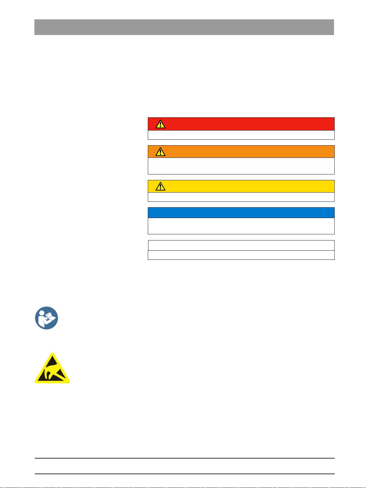
DANGER
An imminent danger that could result in serious bodily injury or death.
WARNING
A possibly dangerous situation that could result in serious bodily injury
or death.
CAUTION
A possibly dangerous situation that could result in slight bodily injury.
NOTICE
A possibly harmful situation which could lead to damage of the product
or an object in its environment.
IMPORTANT
Application instructions and other important information.
bеЦдблЬ
Accompanying documents
Electrostatic discharge (ESD)
2.2
2.3
Tip: Information on making work easier.
Information on the unit
Information on the unit
The symbol “Refer to Operating Instructions” is affixed next to the rating
plate.
The Operating Instructions are provided on an electronic data carrier.
This is delivered together with the treatment center.
Connector pins or sockets bearing ESD warning labels must not be
touched or interconnected without ESD protective measures. See also
"Electrostatic discharge" [ → 19] and "Electromagnetic
compatibility" [ → 19].
On-site installation
On-site installation
The on-site installation must have been performed according to our
requirements. The details are described in the document "Installation
Requirements."
63 22 726 D3561
D3561.201.01.03.02 05.2012
15
Page 16

2 Safety instructions Sirona Dental Systems GmbH
2.4 Media quality Operating Instructions SINIUS / SINIUS CS
2.4
Media quality
Media quality
The air and water supplies must meet the requirements specified in the
installation instructions. Use only drinking water and dry, oil-free and
hygienically clean air for the water and air supplies of the treatment
center.
Disinfection system, optional
To ensure compliance with the medical and national legal requirements
for water from treatment centers, Sirona recommends equipping the
treatment center with a disinfection system. If you decide to operate the
treatment center without a disinfection system, you must make alternative
arrangements to ensure good water quality.
As the owner of the treatment center, you are generally responsible for
the water quality.
For this reason, you should check the water quality at regular intervals,
see "Microbiological inspection of the water" [ → 170]. Please contact your
specialized dealer or your relevant dental association for the respective
national requirements and measures. Where necessary, you must make
alternative arrangements to ensure good water quality if you decide to
operate the treatment center without a disinfection system.
Immunosuppressed patients, with sterile solution
Highly immunosuppressed patients should not come in contact with water
from the treatment center. The use of sterile solutions is recommended.
Authorized technical personnel and
spare parts
2.5
2.6
Connection to the public drinking water system
Free discharge where no disinfection system exists
Connection to the publ ic drinking water s ystem
Provided it is equipped with a disinfection system, the treatment center
provides free discharge in the water supply (isolating distance ≥ 20 mm).
This isolates the public drinking water system from the water supplies
following free discharge. The requirements of EN 1717 are thereby
fulfilled.
The treatment center meets the requirements of the DVGW (German Gas
and Water Association).
It is intrinsically safe in accordance with worksheet W540 and therefore
fulfills the requirements of W270 and KTW (plastics in waterways). The
German Gas and Water Association (DVGW) approval can be viewed on
a label next to the rating plate.
Structural measures if no disinfection system is availabl e
Provided the treatment center is not equipped with a disinfection system,
structural measures may be required beyond the unit to protect the public
drinking water system.
Please always adhere to the national requirements with regard to
connecting treatment centers to the public drinking water system.
Maintenance and repair
Maintenance and repair
As manufacturers of dental medical units and in the interest of the
operational safety of your system, we stress the importance of having
maintenance and repair of this unit performed only by ourselves or by
agencies expressly authorized by us. Furthermore, failed components
must always be replaced with original spare parts.
Certificate, with modification n ote
We suggest that you request a certificate showing the nature and extent
of the work performed from those who carry out such work; it must contain
63 22 726 D3561
16 D3561.201.01.03.02 05.2012
Page 17
Sirona Dental Systems GmbH 2 Safety instructions
Operating Instructions SINIUS / SINIUS CS 2.7 Trouble-free operation
any changes in rated parameters or working ranges (if applicable), as well
as the date, the name of the company and a signature.
Maintenance intervals Despite the outstanding quality of your treatment center and regular care
by the practice team, in the interest of operational safety, it is essential to
have preventive maintenance performed at scheduled intervals.
In order to ensure the operational safety and reliability of your treatment
center and to avoid damage due to natural wear, you as the system owner
must have your system checked regularly by an authorized service
engineer from your dental depot. Furthermore, safety checks must be
performed. Please contact your dental depot to obtain a maintenance
offer. For more information, please refer to "Maintenance by the service
engineer" [ → 217].
2.7
2.8
2.9
Trouble-free operation
Trouble-free operation
Use of this unit is permissible only if it works properly without
malfunctions. If trouble-free operation cannot be ensured, the unit must
be taken out of service, checked by authorized technicians for
malfunctions and, if necessary, repaired.
Vacuum system
Suction of aluminum or other metal oxides prohibited
Vacuum system
The suction removal of aluminum and other metal oxides from blasting
devices via the amalgam separator and the automatic separator installed
in the treatment center is prohibited! This would result in extreme wear
and clogging of the vacuum and drain lines.
Separate suction
A separate vacuum system must be used in connection with metal oxide
blasting devices. Treatment centers equipped with a central wet suction
system are generally suitable for suction removal of the above material.
However, make sure to observe the instructions provided by the
manufacturer of your vacuum system.
Suction of steel abrasives perm issible
No restrictions apply when using salt blasting devices in connection with
Sirona treatment centers. However, in such cases, make sure that the
system is subsequently flushed with an adequate amount of water.
Patient chair
Patient chair
Please observe the maximum load capacity of 165 kg for the patient
chair.
bеЦдблЬ
63 22 726 D3561
D3561.201.01.03.02 05.2012
The weight distribution complies with ISO 6875. The mechanical stability
test is performed with a multiple safety factor according to IEC 60601-1.
The maximum permissible weight of accessories mounted on the patient
chair is 5 kg.
The patient’s arms and legs must be resting on the upholstery of the
chair.
17
Page 18

2 Safety instructions Sirona Dental Systems GmbH
2.10 Ventilation slots Operating Instructions SINIUS / SINIUS CS
2.10
2.11
2.12
Ventilation slots
Ventilation slots
Under no circumstances may the ventilation slots on the unit be covered,
since otherwise the air circulation will be obstructed. This can cause the
unit to overheat.
Do not spray liquids such as disinfectants into the ventilation slots. This
may lead to malfunctions. Use wipe disinfection only in the vicinity of the
ventilation slots.
Intermittent operation
Intermittent operation
The motors of the treatment center and of the treatment instruments are
designed for intermittent operation corresponding to the dental mode of
treatment.
Intermittent operation, max. 10% duty cycle, cycle duration 1200s
Drive motors for patient chair and backrest: max. 10% duty cycle, cycle
duration 1200s
Touchscreen
Touchscreen
The monitor of the dentist element is equipped with touch-sensitive
control technology.
The touchscreen must not be operated with pointed objects such as ballpoint pens, pencils, etc. Such objects could damage or scratch its
surface. Always operate the touchscreen by pressing it gently with your
fingertip.
2.13
2.14
Care and cleaning agents
Care and cleaning agents
Unsuitable care and cleaning agents may corrode the surface of the unit
or impair its functioning.
Therefore, use only care and cleaning agents which have been approved
by Sirona. For more information, please refer to "Care and cleaning
agents" [ → 170].
Modifications and extensions of the system
Modifications and exte nsions of the sys tem
Modifications to this system which might affect the safety of the system
owner, patients or other persons are prohibited by law.
For reasons of product safety, this product may be operated only with
original Sirona accessories or third-party accessories expressly approved
by Sirona. The user assumes the risk of using non-approved accessories.
If any devices not approved by Sirona are connected, they must comply
with the applicable standards, e.g.:
● IEC 60950 for information technology equipment (e.g. PC) and
● IEC 60601-1 for medical electrical equipment.
The treatment center monitor must fulfill the requirements of the
IEC 60950 standard.
The loudspeaker port of the monitor may be connected only to a device
that complies with IEC 60950 (e.g. a PC) or
63 22 726 D3561
18 D3561.201.01.03.02 05.2012
Page 19
Sirona Dental Systems GmbH 2 Safety instructions
Operating Instructions SINIUS / SINIUS CS 2.15 Electromagnetic compatibility
IEC 60601-1. Under no circumstances may it be connected to a stereo
system, or similar, for example.
If a system is created during the installation process, the requirements of
IEC 60601-1, 3rd edition, must be fulfilled. The system author assumes
responsibility for conformity of the system with 93/42/EEC Directive.
2.15
Electromagnetic compatibility
Electromagnetic compatibility
Medical electrical devices are subject to special precautionary measures
with regard to electromagnetic compatibility (EMC). They must be
installed and operated as specified in the document “Installation
Requirements”.
Portable and mobile RF communications equipment may interfere with
medical electrical equipment. Therefore, the use of such devices (e.g.
cellular phones) in practice or hospital environments must be prohibited.
SIVISION digital and USB interface
The presence of electromagnetic interference in the vicinity of the
treatment center may cause image degradation and interruptions in the
data transmission via the USB interface to the PC. In such cases please
repeat the image recording or other operations.
In the event of heavy interference, it may be necessary to restart the PC.
It is therefore not recommended to use the PC for controlling other
devices that provide essential performance components.
Wireless foot control
The wireless foot control may interfere with other devices in the same
frequency band (2.4 GHz) or receive interfering signals from them. The
safe condition of the treatment center is guaranteed even if the wireless
transmission is compromised.
bеЦдблЬ
63 22 726 D3561
D3561.201.01.03.02 05.2012
2.16
Electrostatic discharge
Electrostatic discharge
Protective measures
Electrostatic discharge (abbreviated: ESD – ElectroStatic Discharge)
Electrostatic discharge from people can damage electronic components
when the components are touched. Damaged components usually have
to be replaced. Repairs must be performed by qualified personnel.
Measures to protect against ESD include:
● Procedures to avoid electrostatic charging via
– air conditioning
– air humidification
– conductive floor coverings
– non-synthetic clothing
19
Page 20
2 Safety instructions Sirona Dental Systems GmbH
2.16 Electrostatic discharge Operating Instructions SINIUS / SINIUS CS
● discharging the electrostatic charges from your own body through
contact with
– the metallic device casing
– a larger metallic object
– another grounded protective ground wire
● wearing an antistatic band that creates a connection between the
body and a protective ground wire.
Areas at risk are indicated on the unit with the ESD warning label:
We recommend that all persons working with this system are made aware
of the significance of the ESD warning label. A training course should also
be held to inform users about the physics of electrostatic charges.
Physics of electrostatic charges
An electrostatic discharge requires prior electrostatic charging.
There is a danger of electrostatic charges building up whenever two
bodies rub against each other, e.g. when:
● walking (soles of shoes against the floor) or
● driving (tires against the road surface).
The amount of charge depends on several factors: The charge is:
● higher at low air humidity than at high air humidity, and
● higher with synthetic materials than with natural materials (clothing,
floor coverings).
The following rule of thumb can be applied to assess the transient
voltages resulting from an electrostatic discharge.
An electrostatic discharge is:
● perceptible at 3,000 V or higher
● audible at 5,000 V or higher (cracking, crackling)
● visible at 10,000 V or higher (spark-over)
The transient currents resulting from these discharges have a magnitude
of 10 amps. They are not hazardous for humans because they last for
only several nanoseconds.
Tip: 1 nanosecond = 1/1,000,000,000 second = 1 billionth of a second
Voltage differentials exceeding 30,000 volts per centimeter may lead to a
charge transfer (electrostatic discharge, lightning, spark-over).
Integrated circuits (logical circuits and microprocessors) are used in order
to implement a wide variety of functions in a device. The circuits must be
miniaturized to a very high degree in order to include as many functions
as possible on these chips. This leads to structure thicknesses as low as
a few ten thousandths of a millimeter. Integrated circuits that are
connected to wires leading externally are therefore particularly at risk
from electrostatic discharge.
Even voltages that are imperceptible to the user can cause breakdown of
the structures, thus leading to a discharge current that melts the chip in
63 22 726 D3561
20 D3561.201.01.03.02 05.2012
Page 21

Sirona Dental Systems GmbH 2 Safety instructions
Operating Instructions SINIUS / SINIUS CS 2.17 Dismantling/Installation
the affected areas. Damage to individual integrated circuits may cause
malfunction or failure of the unit.
2.17
Dismantling/Installation
Follow the installation instruc tions
Dismantling/Installation
When dismantling and reinstalling the unit, proceed according to the
installation instructions for new installation in order to guarantee its proper
functioning and stability.
bеЦдблЬ
63 22 726 D3561
D3561.201.01.03.02 05.2012
21
Page 22
3 Unit description Sirona Dental Systems GmbH
0123
SIRONA
Dental Systems
GmbH
64625 Bensheim
Fabrikstrasse 31
Z-64.1-14
3.1 Standards/Approvals Operating Instructions SINIUS / SINIUS CS
Unit description
3
Unit description
3.1
Standards/Approvals
Compliance with standards, without HF surgery
Standards/Approvals
The SINIUS / SINIUS CS® treatment center complies with the following
standards, among others:
● IEC 60601-1 (electrical and mechanical safety plus software
reliability)
● IEC 60601-1-2 (electromagnetic compatibility)
● IEC 60601-1-6 (serviceability)
● ISO 6875 (Patient chair)
● ISO 7494-1 (Dental treatment devices)
● ISO 7494-2 (dental treatment units, water and air supply)
● ISO 9680 (Operating light)
● ISO 11143 (amalgam separator), see also below
(if amalgam separator option is present)
● EN 1717 (connection to the drinking water system), see also below and
the chapter titled "Connection to the drinking water system“ [ → 16]
Original language: German
CE mark of the BHE
This product bears the CE mark in accordance with the provisions of
Council Directive 93/42/EEC of June 14, 1993 concerning medical
devices.
Ü mark of the amalgam separator
The amalgam separator achieves a separation efficiency of > 95%. The
unit thus fulfills the requirements of ISO 11143.
Separating procedure type 1: Centrifugal system
The amalgam separator is approved by the German Institute for
Structural Engineering (DIBT) and by the French International
Organization for Standardization (AFNOR).
German Gas and Water Asso ciation (DVGW) certified connection for G ermany
When equipped with a disinfection system, the treatment center complies
with the technical rules and requirements on safety and hygiene for
connection to the public drinking water supply. The unit is certified
according to the requirements of the DVGW (Deutscher Verein für Gas
und Wasser = German Gas and Water Association). It is intrinsically safe
in accordance with worksheet W540. The unit also meets, therefore, the
requirements of standard EN 1717; see also the chapter entitled
"Connection to the public drinking water system" [ → 16].
BELG AQUA for Belgium
This unit meets the requirements of BELGAQUA and may therefore be
connected to the public drinking water supply in Belgium.
63 22 726 D3561
22 D3561.201.01.03.02 05.2012
Page 23
Sirona Dental Systems GmbH 3 Unit description
WaterMark
TM
ATS 5200.104
Certificate No. 21208
Operating Instructions SINIUS / SINIUS CS 3.1 Standards/Approvals
or Australia
This unit meets the requirements of ATS and may therefore be connected
to the public drinking water supply in Australia.
CE mark of the wireless foot control
The wireless modules in the wireless foot control and in the treatment
center meet the requirements of the R&TTE directive 1999/5/'EC.
Standards:
● EN 60950-1
● EN 301489-1, EN 301489-17, EN 300328
FCC for wireless foot control
The modules meet the requirements of the Federal Communications
Commission (Part 15 of the FCC Rules).
FCC ID: SIFNANOLOCAVR0108
Industry Canada The modules meet the requirements of Industry Canada (RSS210).
Industry Canada for wireles s foot control
IC: 7654A-nanoLOCAVR
The current approvals of the wireless foot control are listed on the rating
label on the underside of the wireless foot control.
Product name is a registered tr ademark
SINIUS / SINIUS CS® is a registered trademark of Sirona Dental Systems
GmbH.
bеЦдблЬ
63 22 726 D3561
D3561.201.01.03.02 05.2012
23
Page 24
3 Unit description Sirona Dental Systems GmbH
3.2 Technical data Operating Instructions SINIUS / SINIUS CS
3.2
Technical data
Model designation, power ratings
Technical data
Model designation: SINIUS / SINIUS CS
Power connection: 100 - 230 V AC ± 10%
50/60 Hz
Rated current: 2.2 A at 230 V
4.35 A at 115 V
5.0 A at 100 V
also max. 6 A for external devices
Overvoltage category: 2 acc. to IEC 60664-1
Average power consumption
(for dimensioning an air
conditioning system):
Power consumption in
Standby mode:
Main building fuse: Type B automatic circuit breaker
Unit classifications, without HF surgery
Protection class: Class I equipment
Device class in accordance
with Directive 93/42/EEC:
Degree of protection against
electrical shock:
0.25 kW
3 W (without internal mini PC)
100 - 115 V AC: 20 A slow-blow
230 V AC: 16 A slow blow
Class IIa equipment
Type B applied parts
External intraoral camera SiroCam AF.
Namely:
Application part type BF
Degree of protection against
ingress of water:
Ordinary equipment (without protection
against ingress of water)
The foot control has an IP X1 degree of
protection against liquids (drip-proof).
Operating and transport condit i on s
Mode of operation: Continuous operation with intermittent
loading corresponding to the dental
mode of working. [ → 18]
Permanently connected unit.
Transport and storage
conditions:
Temperature: -40 ℃ – +70 ℃
(-40.00 ℃ – 70.00 ℃ )
Relative humidity: 10% – 95%
Barometric pressure: 500 hPa –
1060 hPa
63 22 726 D3561
24 D3561.201.01.03.02 05.2012
Page 25
Sirona Dental Systems GmbH 3 Unit description
20XX
Operating Instructions SINIUS / SINIUS CS 3.2 Technical data
Operating conditions: Ambient temperature: 10°C – 40°C
(50°F – 104°F)
Relative humidity: 30% – 85%
no condensation
Barometric pressure: 700 hPa –
1060 hPa
Installation site: ≤ 3000 m above sea level
Pollution degree: 2 acc. to IEC 60664-1
Approval and year of manufacture
Tests/Approvals: See "Standards/Approvals“ [ → 22].
Year of manufacture:
(on the rating plate)
USB port: corresponds to USB 2.0 standard
Foot control wireless interface
Foot control wireless interface
Model designation: nanoLOC AVR
Frequency: 2.4 GHz – 2.4835 GHz (ISM band)
Transmitting power: < 2 mW (short-range device)
Modulation type: MDMA
Range: approx. 10 m
Approval: See "Standards/Approvals“ [ → 22].
bеЦдблЬ
Minimum PC requireme nts
IMPORTANT
Minimum requirements for PC
See document "Installation instructions and system requirements for PC
configuration," (REF 61 94 075) SIVISION digital.
63 22 726 D3561
D3561.201.01.03.02 05.2012
25
Page 26

3 Unit description Sirona Dental Systems GmbH
3.3 System overview Operating Instructions SINIUS / SINIUS CS
3.3
System overview
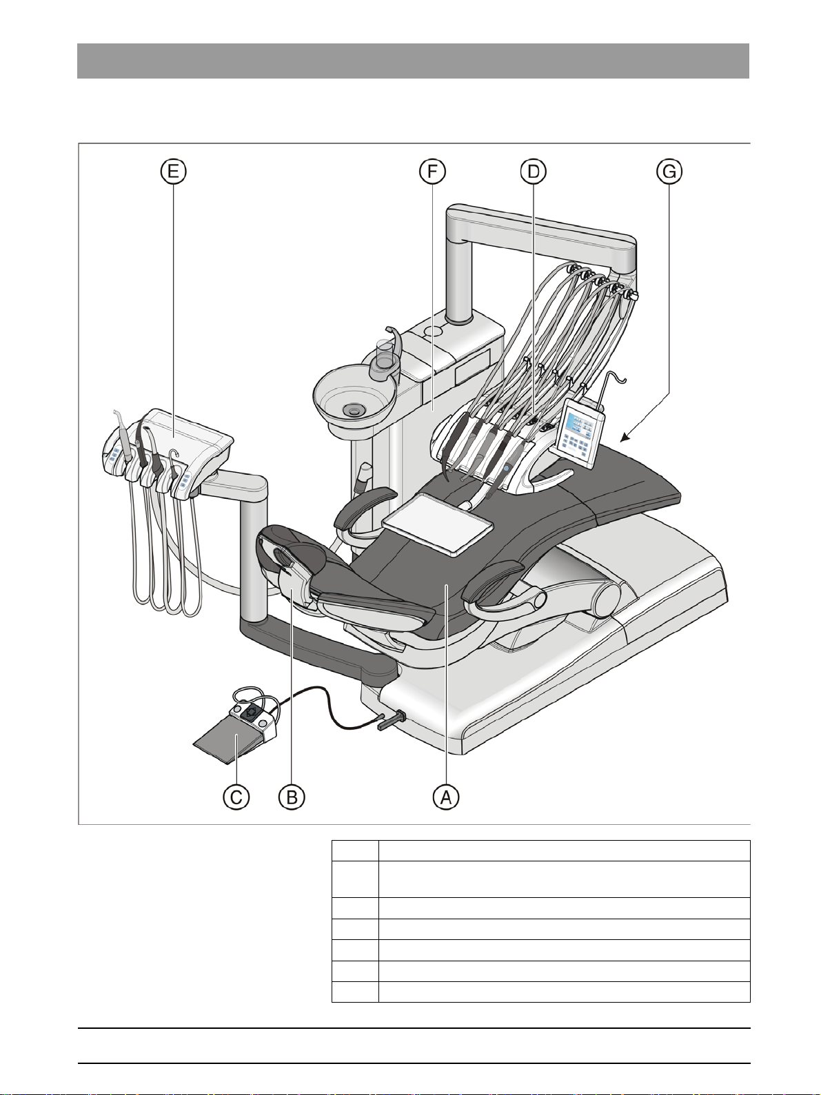
System overview
The SINIUS / SINIUS CS treatment center comprises the following main
components:
SINIUS treatment center
A Patient chair [ → 28]
B Motor-driven headrest [ → 29] (shown here) or Double-jointed
headrest [ → 30]
C Foot control [ → 31] (with cable or wireless link)
D Dentist element SINIUS on the travel track [ → 32]
E Assistant element [ → 39]
F Water unit [ → 41]
G External device connection [ → 43] and power switch
63 22 726 D3561
26 D3561.201.01.03.02 05.2012
Page 27
Sirona Dental Systems GmbH 3 Unit description
Operating Instructions SINIUS / SINIUS CS 3.3 System overview
SINIUS CS treatment center
A Patient chair [ → 28]
B Motor-driven headrest [ → 29] (shown here) or Double-jointed
headrest [ → 30]
C Foot control [ → 31] (with cable or wireless link)
D SINIUS CS dentist element with swivel arms on support arm [ → 32]
E Assistant element [ → 39]
F Water unit [ → 41]
G External device connection [ → 43] and power switch
bеЦдблЬ
63 22 726 D3561
D3561.201.01.03.02 05.2012
27
Page 28
3 Unit description Sirona Dental Systems GmbH
3.4 Patient chair Operating Instructions SINIUS / SINIUS CS
3.4
Patient chair
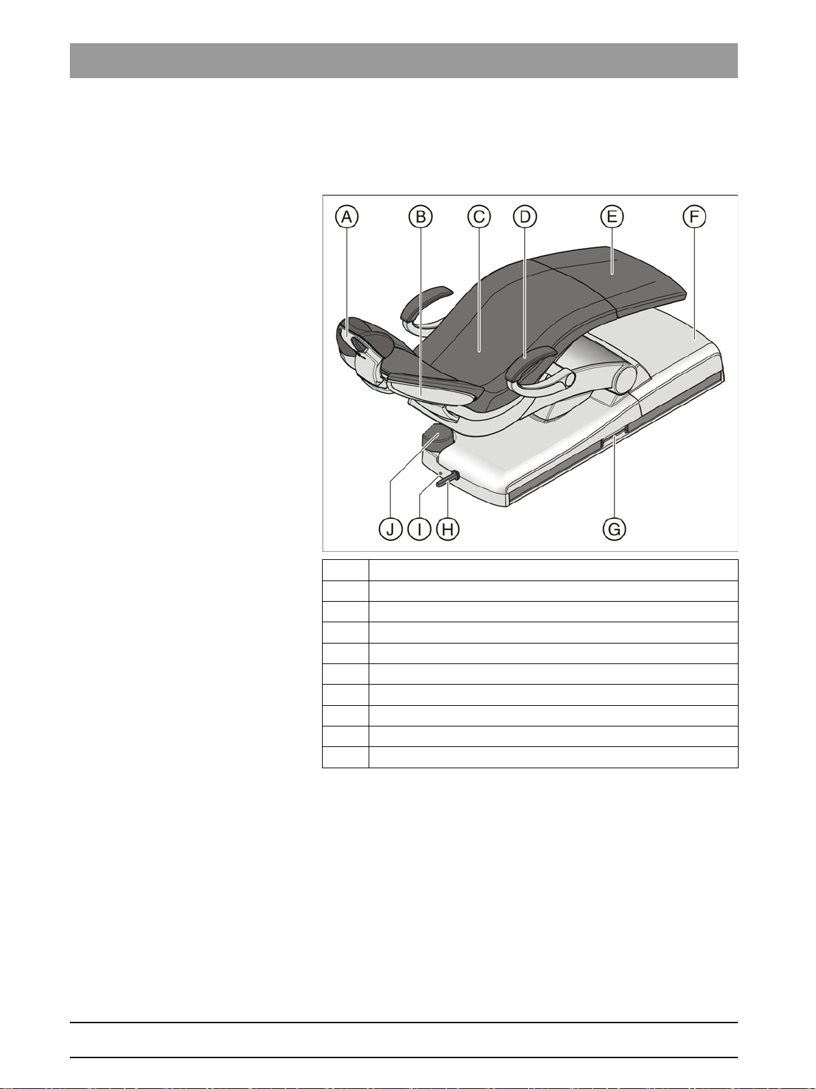
Patient chair
The patient chair features a variety of motor adjustment options to
optimally adapt the patient's position to the given treatment.
A Motor-driven headrest (shown here) or articulating headrest
B Backrest
C Seat
D Armrest
E Footrest
F Chair base
G Flange on the SINIUS dentist element travel track
H 4-way foot switch
I Foot control cable port
J Rotary joint for assistant element
63 22 726 D3561
28 D3561.201.01.03.02 05.2012
Page 29
Sirona Dental Systems GmbH 3 Unit description
D
C
B
A
Operating Instructions SINIUS / SINIUS CS 3.5 Headrest
3.5
Headrest
Headrest
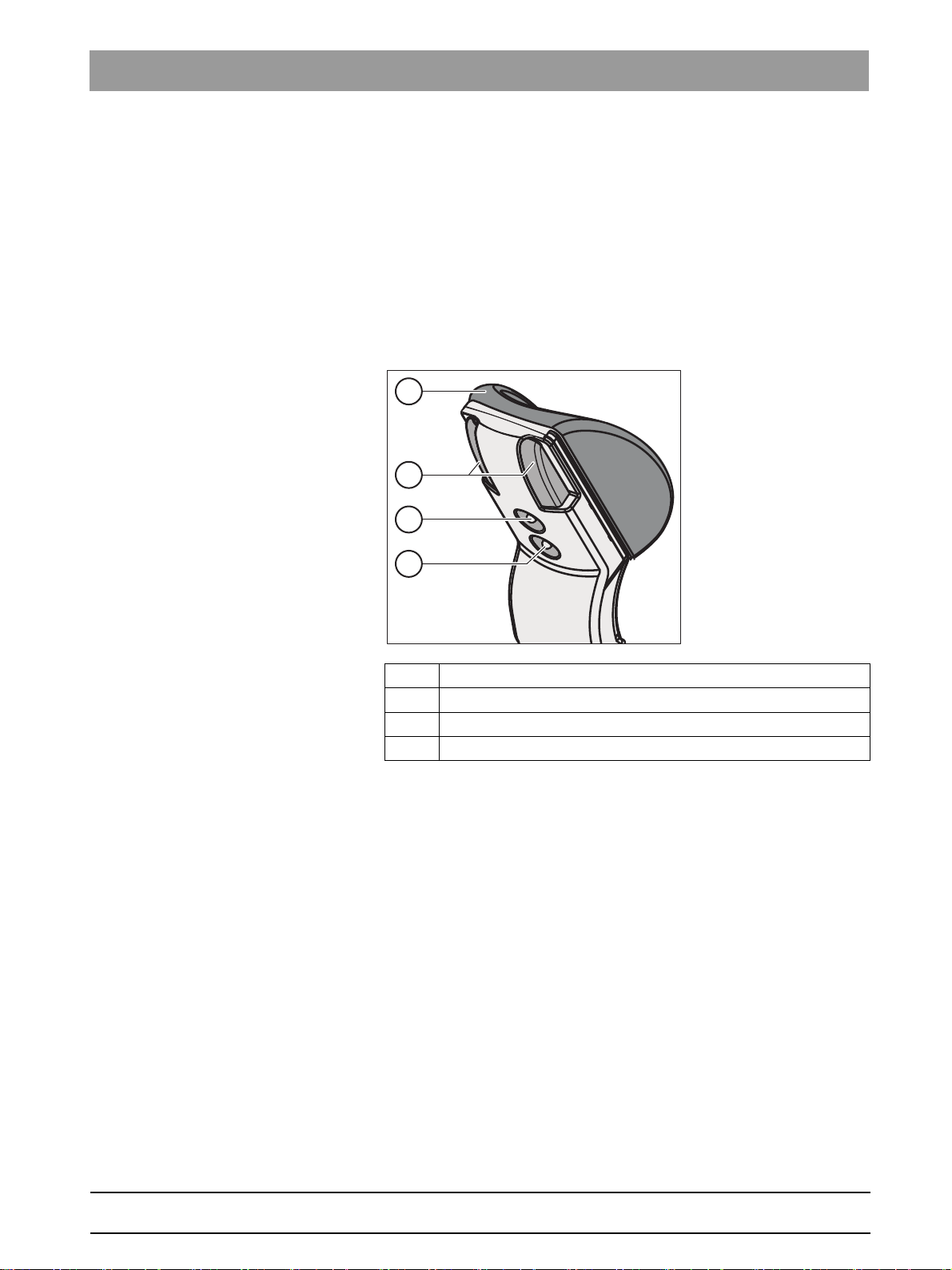
3.5.1 Motor-driven headrest
Motor-driven headrest
The headrest allows for the following adjustment options:
● Motor-driven extension/retraction to adapt to the patient's stature
● Motor-driven tilting for maxillary/mandibular treatment
● Manual tilting via quick mechanical adjustment
● Shifting/rotation of the head support via the magnetic holder
bеЦдблЬ
A Removable head pad with magnetic holder
B Quick mechanical adjustment of headrest tilt
C Upper 4-way switch for headrest functions
D Lower 4-way switch for chair functions
For details, see "Adjusting the motor-driven headrest" [ → 64].
63 22 726 D3561
D3561.201.01.03.02 05.2012
29
Page 30
3 Unit description Sirona Dental Systems GmbH
3.5 Headrest Operating Instructions SINIUS / SINIUS CS
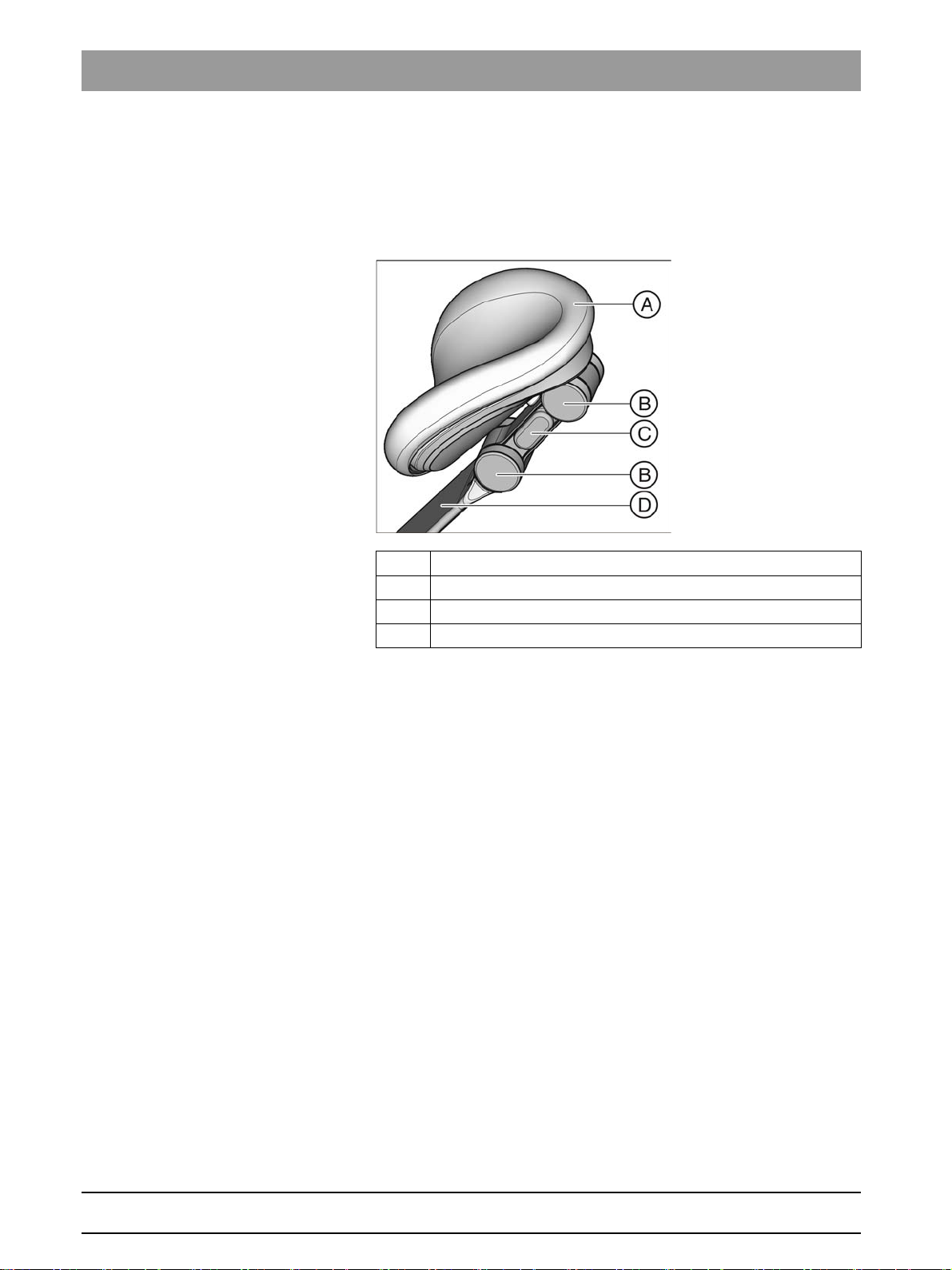
3.5.2 Double-jointed headrest
Double-jointed headres t
The double-jointed headrest is equipped with two rotary joints. They allow
the adjustment of head inclination for maxillary/mandibular treatment to a
great extent. The headrest extension can be pulled in or out to suit the
height of the patient.
A Removable head pad with Velcro fasteners
B Rotary joints
C Unlock button (one-sided)
D Support bar for adjustment to patient height
For details, see "Adjusting the double-jointed headrest" [ → 66].
63 22 726 D3561
30 D3561.201.01.03.02 05.2012
Page 31

Sirona Dental Systems GmbH 3 Unit description
F
E
D
C
B
A
S
0
Operating Instructions SINIUS / SINIUS CS 3.6 Foot control
3.6
Foot control
Foot control
The foot control enables hand-free control of the treatment instruments.
Via the integrated cursor control, virtually all functions of the treatment
center can be controlled via the foot control as an alternative to hand
control.
bеЦдблЬ
A Foot pedal as speed foot control or direct starter
B Left button (program key S or spray)
C 4-way foot control plate for cursor control
D Right button (program key 0 or chip blower)
E Positioning bar
F Connecting cable
The foot control is also available with wireless transmission. The
connecting cable has been omitted for the wireless foot control. The
power supply is provided by a battery, see "Changing the battery of the
wireless foot control" [ → 215].
63 22 726 D3561
D3561.201.01.03.02 05.2012
31
Page 32

3 Unit description Sirona Dental Systems GmbH
3.7 Dentist element Operating Instructions SINIUS / SINIUS CS
3.7
Dentist element
Dentist element
All functions of the treatment center can be controlled via the EasyTouch
control panel on the dentist element. The dental treatment center can be
equipped with the SINIUS dentist element on the travel track or the
SINIUS CS dentist element on a support arm.
SINIUS dentist element
The dentist element can be moved the entire length of the patient chair
along the travel track. In combination with the rotary joints on the support
arm, the dentist element can be perfectly adjusted to suit any treatment.
In this dentist element, the instruments are positioned vertically in the
instrument holders. The instrument hoses hang freely under the dentist
element.
A Removable instrument holder (max. 5 instruments)
B Removable handles (left/right)
C Program change keys
D Touchscreen for display and operation
E Fixed keys
F Main switch
G Skid-proof silicone mat
H Removable NaCI bottle holder
I Additional holder for intraoral camera
J Support arm, height adjustable by service engineer
K Slide of travel track
63 22 726 D3561
32 D3561.201.01.03.02 05.2012
Page 33

Sirona Dental Systems GmbH 3 Unit description
Operating Instructions SINIUS / SINIUS CS 3.7 Dentist element
SINIUS CS dentist element
The SINIUS CS dentist element is attached to the water unit with a flexible
support arm. The support arm is held in place by a pneumatic locking
brake. To release the brake simply touch one of the two handles.
In this dentist element, instruments are arranged in the instrument
holders horizontally and facing downwards. The instrument hoses are
placed above the dentist element over the swivel arm.
A Removable instrument holder (max. 5 instruments)
B Tray on the dentist element
C Handles (left/right) with integrated switch for releasing the
support arm brake
D Main switch
E Fixed keys
F Program change keys
G Touchscreen for display and operation
H Removable NaCI bottle holder
I Swivel arm
J Support arm
bеЦдблЬ
63 22 726 D3561
D3561.201.01.03.02 05.2012
33
Page 34

3 Unit description Sirona Dental Systems GmbH
3.7 Dentist element Operating Instructions SINIUS / SINIUS CS
3.7.1 Instrument positions
Instrument positions
The following instrument positions are available:
Holder 1 Holder 2 Holder 3 Holder 4 Holder 5
SPRAYVIT M
multifunctional
syringe
Motors:
• BL
• BL ISO S
• BL ISO C
Highspeed
handpiece
Motors:
• BL
• BL ISO S
• BL ISO C
Highspeed
handpiece
Motors:
• BL
• BL ISO S
• BL ISO C
Highspeed
handpiece
SIROSONIC TL
SIROSONIC TL
scaler
SiroCam AF
intraoral camera
1
scaler
1
A maximum of one SIROSONIC TL scaler can be connected.
2
Only the SINIUS dentist element can be equipped with an additional
holder.
Additional holder
1
SiroCam AF
intraoral camera
2
63 22 726 D3561
34 D3561.201.01.03.02 05.2012
Page 35

Sirona Dental Systems GmbH 3 Unit description
Operating Instructions SINIUS / SINIUS CS 3.7 Dentist element
3.7.2 EasyTouch user interface
EasyTouch user interface
User interface of the SINIUS dentist element
User interface of the SINIUS CS dentist element
A Fixed keys for opening the Start, Instrument or SIVISION
screen (membrane keyboard)
B Touchscreen (pressure-sensitive user interface)
C Fixed keys (membrane keyboard)
D Main switch
bеЦдблЬ
63 22 726 D3561
D3561.201.01.03.02 05.2012
35
Page 36

3 Unit description Sirona Dental Systems GmbH
3.7 Dentist element Operating Instructions SINIUS / SINIUS CS
3.7.3 Touchscreen
Touchscreen
The touchscreen displays virtual function keys according to the program
selected. A list of all function keys is provided in the Appendix of this
document, see "Overview of all function keys" [ → 225].
Some programs are divided into a main program and sub-screens. The
main programs are briefly introduced below:
Start program The Start program can be displayed in the
or
instrument functions
Start program with instrument functions
mode. For details on both operating modes, see “Instrument functions in
Start program" [ → 49].
Start program without instrument functions (left) and with instrument functions
(right)
Instrument program The
Start program without instrument functions
instrument program for the removed instrument. The Instrument
programs can be displayed either with the quick setting keys or via the
function levels. For details, see "Quick setting keys and function levels".
Start program without
operating
mode displays the
Motor screen with quick setting keys (left) and function levels (right)
SIVISION program The SIVISION program allows for controlling certain computer programs
running on the external PC directly from the treatment center. For details,
see "External / internal PC" [ → 152].
SIVISION program
63 22 726 D3561
36 D3561.201.01.03.02 05.2012
Page 37

Sirona Dental Systems GmbH 3 Unit description
Operating Instructions SINIUS / SINIUS CS 3.7 Dentist element
3.7.4 Fixed keys on the dentist element
Fixed keys on the dentist element
For a more detailed description of the fixed key functions, see "Fixed keys
on the dentist element" [ → 76].
Fixed keys on the dentist eleme nt
Main switch
Switches the treatment center on/off.
To switch off the treatment center, press and hold the key until an
acoustic signal sounds. Then release the key.
Power switch
IMPORTANT
Power switch
The treatment center also features a power switch on the base of the
chair that separates the treatment center from the power supply, see
"Switching the treatment center on/off" [ → 45].
Program change keys
The program change keys allow the user to switch between the main
programs
the
In the
keys
screens.
Start program, Instrument program
Start program without instrument functions
Start program with instrument functions
Chair
and
Instrument
can be used to switch to the relevant sub-
and
mode.
mode the program change
SIVISION program
in
bеЦдблЬ
Timer function
Opens the
Timer Function
screen where any of four preset timers can be
activated. The time lapse is displayed in the footer of the touchscreen.
When the
Timer Function
key is pressed (> 2 s), the
Timer Function
settings screen appears.
Shock positioning
Immediately moves the patient chair to a position for shock positioning of
the patient.
Operating light
Switches the operating light on/off.
When the operating light key is pressed (> 2 s), the
Light Intensity
settings screen appears (not in the case of the LEDview S).
Composite function
Switches the composite setting for the operating light on/off.
This function is required to prevent the premature curing of composite
fillings.
Reduced light intensity < 8,000 lux
Tumbler filling
Starts or stops the tumbler filling function.
63 22 726 D3561
D3561.201.01.03.02 05.2012
When the
Tumbler filling
key is pressed (> 2 s), the filling time and water
heating settings screen appears.
37
Page 38

3 Unit description Sirona Dental Systems GmbH
3.7 Dentist element Operating Instructions SINIUS / SINIUS CS
Flushing
Starts or stops the flushing of the cuspidor bowl.
When the
Flushing
key is pressed (> 2 s), the
Flushing Time
settings
screen appears.
Freely selectable function
e.g. call key
Freely available relay 230 VAC, 6 A
(connected by the service engineer).
This function can be preset as a button or as a switch in the Setup
program.
Freely selectable function
Freely available relay 230 VAC, 6 A
(connected by the service engineer).
This function can be preset as a button or as a switch in the Setup
program.
Clean key
Pressing this key deactivates the complete user interface of the dentist
element. Pressing it again > 2 s reactivates the control panel.
This is used to make sure that no unwanted functions can be accidentally
triggered while cleaning the surface.
Setup key
Used for individual configuration of the treatment center by the user and
for reading out messages by the service engineer, see "Configuration of
the treatment center (Setup)" [ → 157].
63 22 726 D3561
38 D3561.201.01.03.02 05.2012
Page 39

Sirona Dental Systems GmbH 3 Unit description
Operating Instructions SINIUS / SINIUS CS 3.8 Assistant element
3.8
Assistant element
Assistant element
The functional scope of the assistant element is adapted to the dental
assistant's field of activity. It can, however, also be positioned so as to
enable unassisted treatment by the dentist.
bеЦдблЬ
A Holders 1 to 4 (from left to right) for instruments
B User interfaces (left/right)
C Removable handle
D Removable instrument holder
E 3 rotary joints for flexible positioning
F Support arm
3.8.1 Instrument positions
Instrument positions
The following instrument positions are available:
Holder 1 Holder 2 Holder 3 Holder 4
Mini L.E.D. curing light SPRAYVIT M
multifunctional syringe
1
SiroCam AF
camera
intraoral
1
Only the SINIUS CS treatment center can be equipped with an intraoral
camera on the assistant element.
Spray aspirator Saliva ejector
63 22 726 D3561
D3561.201.01.03.02 05.2012
39
Page 40

3 Unit description Sirona Dental Systems GmbH
3.8 Assistant element Operating Instructions SINIUS / SINIUS CS
3.8.2 User interface
User interface
There are three fixed keys located on each side, to the left and right of the
assistant element.
3.8.3 Fixed keys on the assistant element
Fixed keys on the as sistant element
For a more detailed description of the fixed key functions, see "Fixed keys
on the assistant element" [ → 125].
Fixed keys on the assi stant element
Tumbler filling
on/off
Flushing of the cuspidor bowl
on/off
Operating light/Composite function
Switches the operating light on/off.
Switches the composite setting for the operating light on/off.
Reduced light intensity< 8,000 lux
Chair program S
Mouth rinsing position with last-position memory function
(programmable)
Chair program 0
Entry/exit position (programmable)
Freely selectable function
Hash key
The
program. The key allows the user to switch the X-ray viewer or the white
screen function on the SIVISION monitor on or off or alternatively to
activate the bell or hash relay.
on the assistant element can be configured in the Setup
Freely available relay 230 VAC, 6 A
(connected by the service engineer).
63 22 726 D3561
40 D3561.201.01.03.02 05.2012
Page 41

Sirona Dental Systems GmbH 3 Unit description
Operating Instructions SINIUS / SINIUS CS 3.9 Water unit
3.9
Water unit
Disinfection system
Water unit
The water unit can optionally be equipped with a disinfection system. It
adds a disinfectant to the water the patient comes in contact with. This
reduces the amount of germs in the water lines. If you decide to operate
the treatment center without the disinfection system, please refer to the
information in the chapter "Media quality" [ → 16].
Water lines, microorganism s, optional disinfection system
WARNING
Microorganisms can multiply in the water.
These microorganisms could increase the risk of damage to one's
health.
➢ If the treatment center is equipped with a disinfection system, never
operate this without disinfectant.
The water unit can be optionally equipped with an automatic separator
(separation of suction air and waste water) combined with an amalgam
separator/sediment container or with a wet suction device.
The top cover of the water unit has an integrated receptacle for watercarrying instruments and suction hoses. The dentist element and
assistant element instruments are plugged in with adapters on both sides
of the water unit. The openings are covered with flaps. The receptacle is
required for the sanitation of the treatment center, the automatic purge of
the water lines (AutoPurge) and for the cleaning of the suction hoses.
bеЦдблЬ
The vacuum system can be cleaned by pumping water into a tank behind
the receptacle and extracting it from there. If the treatment center is
equipped with the chemical hose cleaning option, a cleaning agent is
automatically added to the water. For more information, please refer to
"Cleaning the suction hoses" [ → 192].
63 22 726 D3561
D3561.201.01.03.02 05.2012
41
Page 42

3 Unit description Sirona Dental Systems GmbH
3.9 Water unit Operating Instructions SINIUS / SINIUS CS
Key with disinfection system
A Suction hose connection for assistant element
B Manually swiveling cuspidor
C Tumbler filler (depicted) or tumbler filler with automatic sensor
control for automatic filling of the tumbler
D Cover of disinfectant tank
The tank can also be used as a self-sufficient water supply. In
this case, distilled water is mixed with the DENTOSEPT P
disinfectant in a 100:1 ratio (1 liter of water, 10 ml of
DENTOSEPT P) and filled into the disinfectant tank, see "Self-
sufficient water supply" [ → 135]
E Mount for support arm of operating light and monitor
F Mount for SINIUS CS dentist element or tray support arm
G Mount for water-carrying instruments of the dentist element for
sanitation and AutoPurge. The mount for the SPRAYVIT M and
the suction hoses of the assistant element are located on the
opposite side.
H Maintenance flap for accessing the cleaning agent tank to
chemically clean the suction hoses, the flushing valve, the
potentiometer of the automatic sensor control, the amalgam
separator, sediment container or filter insert for wet suction
63 22 726 D3561
42 D3561.201.01.03.02 05.2012
Page 43

Sirona Dental Systems GmbH 3 Unit description
Operating Instructions SINIUS / SINIUS CS 3.10 Outlet for add-on devices
3.10
Outlet for add-on devices
Outlet for add-on devices
External medical accessories can be connected to the external device
connection. They must comply with the requirements of the Medical
Device Directive 93/42/EEC.
Additional devices, hydrogen peroxide up to 0.2‰, disinfection system optional
NOTICE
If the treatment center is equipped with a disinfection system, additional
devices are exposed to a hydrogen peroxide concentration ((H
0.1‰-0.2‰ at the external device connection.
If the additional devices are not suitable for the specified hydrogen
peroxide concentration, they may be damaged.
➢ Before connecting any additional devices, check to make sure that
they can be exposed to the above hydrogen peroxide concentration.
Contact the manufacturer of the relevant additional device, if
necessary.
➢ Prior to sanitation, additional devices must be unplugged from the
external device connection (water connection), see "Sanitizing the
treatment center" [ → 207].
External device connecti on, DVGW with additional devices, disin fection system optional
IMPORTANT
DVGW approval
2O2
) of
bеЦдблЬ
As the treatment center is designed according to EN 1717/DIN 1988
(DVGW requirements), the connected additional devices also fulfill the
requirements of the above standards when a disinfection system is
integrated, see "Standards and approvals" [ → 22].
External device connect ion, inlet connector
IMPORTANT
Self-contained power supply
The inlet connector remains live when the power switch is turned off.
The connected external devices therefore must possess their own
power switch.
However, the air and water connections are switched off.
63 22 726 D3561
D3561.201.01.03.02 05.2012
A Inlet connector with power supply (max. 6 A)
B Fuse for inlet connector (6.3 A slow-blow)
43
Page 44

3 Unit description Sirona Dental Systems GmbH
3.10 Outlet for add-on devices Operating Instructions SINIUS / SINIUS CS
C Quick coupling for air
D Quick coupling for water
Pressure Flow rate
Water 2.2 ± 0.2 bar max. 300 ml/min
Air 4.4 ± 0.5 bar max. 70 Nl/min
63 22 726 D3561
44 D3561.201.01.03.02 05.2012
Page 45

Sirona Dental Systems GmbH 4 Operation
Operating Instructions SINIUS / SINIUS CS 4.1 Starting up the treatment center
Operation
4
Operation
4.1
Starting up the treatment center
Starting up the treatment center
4.1.1 Initial startup
Initial startup
Sanitation must be performed prior to initial startup of your treatment
center.
This is done by filling all water-bearing lines with DENTOSEPT P
concentrated disinfectant to reduce the exposure of the water to bacteria.
SINIUS reference
If the service engineer skipped the sanitation procedure after installing
your treatment center based on an agreement with you or sanitation has
not been performed for more than one week, please perform sanitation
yourself. Refer to "Sanitizing the treatment center" [ → 207] for more
information.
Sanitation takes approx. 24 hours.
4.1.2 Switching the treatment center on/off
Switching the treatment center on/o ff
The treatment center is equipped with a standby system for enhanced
convenience when switching it on and off at the dentist element.
The treatment center thus features a power switch at the base of the chair
and a main switch on the dentist element.
bеЦдблЬ
4.1.2.1
Power switch
Power switch
The power switch connects the treatment center to the power supply.
During longer periods of disuse, the treatment center should be
disconnected from the power supply. It then no longer consumes any
energy.
The power switch contains an automatic device fuse.
Connecting the treatment center to the power supply
✔ The treatment center is installed by authorized technical personnel
according to the "Installation Instructions".
➢ Turn on power switch A.
The treatment center is connected to the power supply.
Disconnecting the treatment center from the power supply
✔ The treatment center is shut down, see "Switching the treatment
center off" (below).
➢ Turn power switch A off.
The treatment center is disconnected from the power supply.
63 22 726 D3561
D3561.201.01.03.02 05.2012
45
Page 46

4 Operation Sirona Dental Systems GmbH
4.1 Starting up the treatment center Operating Instructions SINIUS / SINIUS CS
4.1.2.2
Main switch
Main switch
Switching the treatment center on
The main switch switches the treatment center from Standby mode to
operational readiness.
Following switch-on, the operating system is booted and an automatic
self-test is performed.
✔ The power switch is turned on.
➢ Press the main switch on the dentist element.
The LED of the main switch lights up on the dentist element.
The treatment center powers up and establishes operational
readiness.
If the next maintenance call is due in less than 42 days or the
maintenance deadline has already been exceeded, a message appears
on the touchscreen. For more information, please refer to "Inspection and
maintenance" [ → 217].
Switching the treatment center to the Standby mode
with internal PC
On completing your work, you should switch the treatment center off with
the main switch on the dentist element both for safety reasons and to
reduce its power consumption. Pressing the main switch turns the air and
water supply as well as all electronic components off. Only the standby
circuit is still supplied with voltage. Providing there are no subsequent
devices operating on the external device connection and the treatment
center is not equipped with an internal PC, thein standby mode is approx.
3 W.
➢ Press and hold the main switch on the dentist element until an
acoustic signal sounds. Then release the key.
The treatment center then shuts down and switches itself to the
Standby mode.
The LED of the main switch goes out on the dentist element.
4.1.3 Selecting a user profile
Selecting a user profile
The treatment center enables you to manage up to six user profiles.
Multiple users can operate the treatment center without having to do
without their own individual treatment and operation related settings.
The following is stored in the user profiles:
● Creation of chair programs, see "Creating chair programs and shock
positioning" [ → 72]
● Configurations in the Setup programs, see "Configuration of the
treatment center (Setup)" [ → 157]
● Settings in the instrument programs, see "Saving the instrument
settings" [ → 84]
● Configuration of the SIVISION screen for PC control. The
configuration is saved in the PC application SIUCOM plus that is
installed on the PC.
63 22 726 D3561
46 D3561.201.01.03.02 05.2012
Page 47

Sirona Dental Systems GmbH 4 Operation
A
10:45 B
Operating Instructions SINIUS / SINIUS CS 4.1 Starting up the treatment center
Once the user profile has been selected, the corresponding
configurations and settings become available once again.
If any of the user profiles are not required, their number can be limited,
see "Preselecting the number of user profiles" [ → 160].
The user profiles (A) are distinguished with the letters A to F. The active
user profile, here B, is displayed in the footer of the touchscreen. If only
one user profile is pre-selected, no display is shown. The user profile
used last is automatically used when the treatment center is switched on.
✔ The
➢ Select the desired user profile. Touch the
Tip: The individual user settings can be read out and transferred to other
SINIUS / SINIUS CS treatment centers by a service engineer. The user
profiles in this case have to be set only once.
Start program
necessary.
The user profile displayed in the footer is active.
is displayed on the touchscreen.
User profile
key as often as
bеЦдблЬ
63 22 726 D3561
D3561.201.01.03.02 05.2012
47
Page 48

4 Operation Sirona Dental Systems GmbH
4.2 Control concept of touchscreen Operating Instructions SINIUS / SINIUS CS
4.2
Control concept of touchscreen
Control concept of to uchscreen
4.2.1 Virtual function keys
Virtual function keys
The touchscreen displays virtual function keys according to the program
selected. Required functions can be triggered either by touching the
function keys with your finger or via cursor with the foot control.
Missing function keys
The adjacent illustration shows the touchscreen of a treatment center as
supplied to the customer and maximally equipped.
Function keys for functions which the treatment center equipment does
not include are not displayed on the touchscreen. Moreover, the
touchscreen user interface can be altered via individual Setup changes,
see "Configuration of the treatment center (Setup)" [ → 157].
In the
Start program
equipment options:
● Motor-driven headrest *
● X-ray viewer
● Endodontic treatment *
this includes function keys for the following
Keys marked with * are not displayed in the
functions
. Equipment options can still be available, see “Instrument
Start program with instrument
functions in the Start program" [ → 49].
Furthermore, the screens may vary due to individual Setup settings. The
following configurations may influence the
Start program
, see:
● "Preselecting the number of user profiles" [ → 160]
● "Setting the X-ray viewer key to white screen on SIVISION
monitor" [ → 161]
Key background color
General functions are represented by gray keys. If the corresponding
function is switched on or active, the key is displayed orange.
Keys that initiate a program change or lead to sub-screens and settings
screens are displayed blue.
As long as a key remains activated, its active state is marked by a bold
black border.
63 22 726 D3561
48 D3561.201.01.03.02 05.2012
Page 49

Sirona Dental Systems GmbH 4 Operation
Operating Instructions SINIUS / SINIUS CS 4.2 Control concept of touchscreen
4.2.2 Instrument functions in the Start program
Instrument functions in the Start pr ogram
After the treatment center is switched on the
appears.
The Start program can run in two operating modes. The operating mode
Start program without instrument functions
patient chair and the instruments in a separate screen. The operating
Start program with instrument functions
mode
the patient chair and the instruments which are most important for the
treatment in the same screen.
You can select your preferred operating mode in the treatment center
setup, see “Displaying instrument functions in the Start program" [ → 160].
The operating modes are described in detail below:
Start program without instrument functions
In the
Start program without instrument functions
function keys and, if in case of a motor-driven headrest, the
headrest in/out
functions offered by the treatment center can be used in this operating
mode.
function are displayed on the screen. The full range of
Start program
displays the functions of the
displays the functions of
only the chair program
automatically
Move
bеЦдблЬ
63 22 726 D3561
D3561.201.01.03.02 05.2012
All other chair functions are listed in the separate
screen. This can be accessed via the
Other general functions of the treatment center are listed in the
screen. This can be accessed via the
Manual Chair Adjustment
Sub-screen
Manual Chair Settings
key.
key.
Start
sub-
49
Page 50
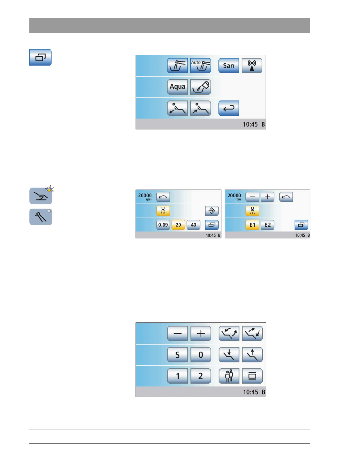
4 Operation Sirona Dental Systems GmbH
4.2 Control concept of touchscreen Operating Instructions SINIUS / SINIUS CS
In the
Start program without instrument functions
will automatically display the instrument program for the removed
instrument instead of the Start program. The program change keys allow
the user to switch between the main programs
Instrument program
via the touchscreen. Speed or intensity values can be adjusted with the
quick setting keys or the function levels.
. All chair and instrument functions can be managed
mode, the touchscreen
Start program
and
Start program with instrument functions
The operating mode
function keys for patient chair programs and manual chair setting, as well
as the – and + keys for speed or intensity adjustment of the instruments
in the same screen. The main keys for the treatment are therefore always
displayed on the touchscreen. Switching between Start program and
Instruments programs does not apply. This makes the operation of the
SINIUS / SINIUS CS dental treatment center similar to other Sirona
dental treatment centers that are operated without a touchscreen.
When an instrument is removed, the
functions
touchscreen. Where applicable, the relevant information is displayed
displays the chosen speed and intensity settings on the
Start program with instrument functions
Start program with instrument
displays the
63 22 726 D3561
50 D3561.201.01.03.02 05.2012
Page 51

Sirona Dental Systems GmbH 4 Operation
Operating Instructions SINIUS / SINIUS CS 4.2 Control concept of touchscreen
during the activation of a preselected coolant and for an activated
counterclockwise rotation.
In the
Start program with instrument functions
keys
Chair
and
Instrument
Other general functions of the treatment center are listed in the
screen; other instrument functions are listed in the sub-screen of the
removed instrument.
can be used to display the relevant sub-screen.
mode the program change
Start
sub-
The functional scope of the treatment center in the
instrument functions
● the motor-driven headrest can only be operated via the 4-way switch
● the speed or intensity levels of instruments are adjusted with the – or
+ keys rather than via quick setting keys or function levels
● the switch coolant on/off function, clockwise/counterclockwise
rotation function and the boost function for the ultrasonic handpiece
must be operated via foot control
● the hands-free touchscreen and fixed key operation via the 4-way
foot control plate of the foot control (cursor control) is not available
● the ApexLocator can only be used for manual measurements using
the file clamp in the
● the treatment function for endodontic treatments is not available
Start program with instrument functions
The
who would like to retain the familiar control concept of other Sirona
treatment centers and who can do without the above functions.
operating mode is limited as follows:
Start
sub-screen
mode is intended for users
Start program with
bеЦдблЬ
63 22 726 D3561
D3561.201.01.03.02 05.2012
51
Page 52

4 Operation Sirona Dental Systems GmbH
A
10:45 B
4.2 Control concept of touchscreen Operating Instructions SINIUS / SINIUS CS
Program change keys
The LED of the relevant program change key will light up in the
program without instrument functions
Start program with instrument functions
In the
Start
sub-screen, in the sub-screen of the removed instrument and in the
according to the selected program.
SIVISION program.
It is not possible:
● to switch to the instrument program or the sub-screen of an
instrument when no instrument has been removed
● to switch to the SIVISION program when the PC connection has not
been configured
You can change from sub-screens and settings screens to a main
program by touching one of the three keys in the
instrument functions
.
4.2.3 Sub-screens and settings screens
Sub-screens and settings screens
Sub-screens
Some programs are divided into a main program and sub-screens.
The function keys for the basic functions are displayed in the main
programs. The
possibilities.
Sub-screen
key (two rectangles) leads to further setting
Start
the LED will light up in the
Start program without
Sub-screens usually are automatically hidden after a certain period has
elapsed. The
immediately.
Settings screens
In many cases, functions not only can be switched on or off, but also can
be set. If a function key is pressed and held (> 2 s), the corresponding
settings screen appears. This screen superimposes the current screen.
The screen located in the background has a semitransparent appearance
and is temporarily disabled for inputs.
Settings screens usually are automatically hidden after a certain period
has elapsed. The
screen immediately.
4.2.4 Footer
Footer
A status line is located at the bottom of the touchscreen. If multiple A user
profiles are preselected, the active user profile A to F is displayed along
with the current time beside it.
Status messages are displayed to indicate, for example, the need to
change the amalgam separator or add disinfectant, the need to charge
the battery of the wireless foot control, error messages, the need to refill
Return
key (return arrow) closes the opened sub-screen
Return
key (return arrow) closes the opened settings
63 22 726 D3561
52 D3561.201.01.03.02 05.2012
Page 53

Sirona Dental Systems GmbH 4 Operation
10:45 B
Endo: ProFile
Operating Instructions SINIUS / SINIUS CS 4.2 Control concept of touchscreen
the cleaning agent for chemically cleaning the suction hoses or the
number of days left until the next maintenance call or sanitation run.
If the treatment function is switched on, the selected treatment and the
assigned burr drive are also displayed here.
bеЦдблЬ
63 22 726 D3561
D3561.201.01.03.02 05.2012
53
Page 54

4 Operation Sirona Dental Systems GmbH
S
0
S
0
4.3 Foot control Operating Instructions SINIUS / SINIUS CS
4.3
Foot control
Foot control
The treatment center can be operated using a wireless foot control or a
foot control with a cable connection.
4.3.1 Wireless foot control
Wireless foot control
Technical data of the wireless module, see Foot control radio
interface" [ → 25].
4.3.1.1
Setting the wireless foot control on the treatment center
Setting the wireless foot control on the treatment center
The wireless foot control must be assigned to the treatment center via a
registration. This prevents malfunctions caused by neighboring wireless
foot controls.
✔ The treatment center and wireless foot control are ready for
operation.
✔ All instruments are in place.
1. Simultaneously press and hold the left and right buttons of the foot
control (> 2 s).
An acoustic signal sounds. The following message appears on
the touchscreen:
If no key is touched, the screen will automatically close after a
specific time. The wireless foot control will not be registered.
2. Confirm that this wireless foot control is to be used on the treatment
Esc
OK
key.
center by pressing the
interrupted with the
The message is hidden. The wireless foot control is assigned to
the treatment center.
4.3.1.2
Battery voltage message
Battery voltage message
The wireless foot control is powered by a battery. An almost empty battery
is detected by the system and displayed in the footer. In this case, the
battery should be replaced within a week to prevent system failure.
When the battery is completely empty, an error code is output, see "Error
messages" [ → 219]. Then the treatment center can no longer be
operated.
The battery can be changed by the user, see "Changing the battery of the
wireless foot control" [ → 215].
4.3.2 Operating the foot control
Operating the foot con trol
The foot control operating elements are assigned different functions,
depending on whether the instruments are all in place or an instrument is
removed from its holder.
button. The registration process can be
63 22 726 D3561
54 D3561.201.01.03.02 05.2012
Page 55

Sirona Dental Systems GmbH 4 Operation
S
0
S
0
S
0
S
S
0
0
Operating Instructions SINIUS / SINIUS CS 4.3 Foot control
Foot control
✔ An instrument is removed.
➢ Step on the foot control.
The instrument is activated. The intensity is regulated according
to the pedal movement if necessary (if the speed foot control is
set, see "General instrument functions" [ → 87]). If the intraoral
camera is removed, the display switches to the still or live image.
4-way foot control plate
If the cursor control is switched on, it is operated via the 4-way foot control
plate, see "Using the cursor control" [ → 56].
If the cursor control is switched off, then:
✔ An electric motor is removed.
➢ Slide the 4-way foot control plate to the right or left.
The CW/CCW rotation of the electric motor is activated.
Foot control, functions durin g ac tiv e treatment
IMPORTANT
Allocation of functions during active treatment
The allocation of functions may differ when the Treatment function is
active.
bеЦдблЬ
➢ Note the position of the orange and blue cursor, see "Using the
cursor control" [ → 56].
Left button
✔ All instruments are in place.
➢ Press the left button.
The chair moves to mouth rinsing position S.
✔ An instrument (motor, highspeed handpiece, SIROSONIC TL) is
removed.
➢ Press the left button.
The cooling system (spray, air, or NaCl) is switched on/off. If the
intraoral camera is removed, the video still image is saved in
SIDEXIS; the live image is displayed in the next quadrant in SI
video.
Right button
✔ All instruments are in place.
➢ Press the right button.
The chair moves to entry/exit position 0.
✔ An instrument (motor, high-speed handpiece) is removed.
➢ Press the right button.
The chip blower remains switched on as long as the button is
pressed. The boost function can be chosen during ultrasound. If
the intraoral camera is removed, it is possible to toggle between
single image and quad image in SI Video.
63 22 726 D3561
D3561.201.01.03.02 05.2012
55
Page 56

4 Operation Sirona Dental Systems GmbH
S
0
4.3 Foot control Operating Instructions SINIUS / SINIUS CS
4.3.3 Using the cursor control
only possible in Start program with instrument functions mode
Using the cursor control
The cursor control cannot be used in the
functions
mode.
Start program with instrument
4.3.3.1
Functionality
Functionality
Cursor control as an alternative mode of operation
The touchscreen and the fixed keys of the dentist element can also be
operated hand-free via the foot control. This method of operation
optimally supports hygiene, especially in connection with sterile treatment
work.
For cursor control, the foot control features a 4-way foot control plate that
can be moved in four directions.
The cursor position is optically displayed on the touchscreen or on the
fixed keys.
The cursor control is reserved for the Start and Instrument programs. The
SIVISION programs cannot be controlled via the cursor.
Cursor control setting options
Note that different settings can be made for the cursor control in the Setup
program. The functions assigned to the 4-way foot control plate vary
according to its setting. The adjacent symbols for setting the cursor are
used in the Setup program.
Without motor-driven travel track
● Cursor control switched off:
Counterclockwise or clockwise instrument motor rotation can be
selected by sliding the 4-way foot control plate to the left or right.
● Cursor control switched on, without program change:
The cursor can be moved along the cursor path by holding or
repeating upward or downward actuation of the 4-way foot control
plate.
● Cursor control switched on, with program change:
The cursor can be moved along the cursor path by holding or
repeating upward or downward actuation of the 4-way foot control
plate. If the cursor is located at the end of the cursor path, it can be
toggled between the Start program and the Instrument program.
Please also note the information on "orange and blue bars," see below.
To set the cursor control to the mode you prefer, refer to "Setting the
cursor control" [ → 160].
Current cursor position
If the cursor control is activated, the current position of the cursor is
displayed by an orange bar located between the pairs of keys on the
touchscreen or between the fixed keys on the EasyTouch control panel.
63 22 726 D3561
56 D3561.201.01.03.02 05.2012
Page 57

Sirona Dental Systems GmbH 4 Operation
S
0
S
0
Operating Instructions SINIUS / SINIUS CS 4.3 Foot control
Cursor path
The cursor path runs between the pairs of keys, moving from top to
bottom and from left to right, usually in multiple loops. The cursor path can
be traversed between the starting and end points either in a forward or a
reverse direction.
If no further cursor position is available on the touchscreen, the cursor
jumps out of the touchscreen. The cursor path is then continued between
the fixed keys on the EasyTouch control panel.
In Instrument programs, all quick setting keys are selected
simultaneously. This is indicated by a horizontal orange bar located
behind the quick setting keys. The speed or intensity is then set by
actuating the 4-way foot control plate to the left or right briefly (values on
quick setting keys) or for a longer time (intermediate values), see
"Operating the cursor control" [ → 58].
The Clean key, Setup routine and main switch cannot be accessed via
the cursor control.
Cursor path on swivel arm d entist element
This picture shows an example of the control panel of the SINIUS dentist
element. The cursor path of the SINIUS CS dentist element also follows
this principle.
Orange and blue bars
bеЦдблЬ
A blue bar indicates which functions are assigned with the left or right
button of the foot control. For example, the mouth rinsing position (S) and
entry/exit position (0) chair programs are assigned in the Start program,
while the Spray and Chip blower are assigned in the Instrument program.
If the cursor control without program change is activated, the blue bars
also can be selected with the cursor. If the cursor control with program
change is activated, the blue bars are skipped for faster navigation.
Cursor return
Once a function is activated with the cursor control, the orange cursor
typically returns to the starting position of the program, for instance after
switching on the X-ray image viewer, the operating light or the cuspidor
flushing. The cursor position will not change for functions that are
operated by permanent shifting of the 4-way foot control plate, e.g.,
manual chair adjustment.
Chip blower key in the Instrument program
When the cursor control is activated, the motor and high-speed
handpiece program will display the
Chip blower
key.
63 22 726 D3561
D3561.201.01.03.02 05.2012
57
Page 58

4 Operation Sirona Dental Systems GmbH
S
0
S
0
S
0
S
0
4.3 Foot control Operating Instructions SINIUS / SINIUS CS
4.3.3.2
Operating the cursor control
Operating the cursor c ontrol
Moving the cursor
➢ Briefly slide the 4-way foot control plate upward or downward.
The orange cursor moves forward or back one cursor position.
➢ Hold the 4-way foot control plate up or down (auto cursor).
The orange cursor slowly moves from one cursor position to
another.
Actuating a function or fixed key
➢ Press left button: Slide the 4-way foot control plate to the left.
Press the right button: Slide the 4-way foot control plate to the right.
The selected key is highlighted orange on the touchscreen (if
switched on) or is displayed in gray or blue (if switched off). The
LED of the selected fixed key lights up or goes out on the control
panel of the dentist element.
The orange cursor usually returns to the starting position of the
program after activation.
Activating a quick setting key and setting intermediate values
Operation of the cursor control for screens with quick setting keys is
illustrated based on the example of the motor screen.
✔ The cursor control is switched on.
1. Move the cursor to the quick setting keys.
The quick setting keys are highlighted with an orange bar.
2. Setting the values of the quick setting keys: Briefly move the 4-way
foot control plate to the left or right.
Setting the intermediate values: Move the 4-way foot control plate to
the left or right and hold it in this position.
The motor speed is displayed in the first line. If the motor is set to
a value corresponding to one of the quick setting keys, it is
highlighted orange.
63 22 726 D3561
58 D3561.201.01.03.02 05.2012
Page 59

Sirona Dental Systems GmbH 4 Operation
S
0
Operating Instructions SINIUS / SINIUS CS 4.3 Foot control
Changing programs
✔ Cursor control with program change is switched on.
1. Position the cursor at the starting point of the cursor path.
2. Move the cursor past the start position. Hold the 4-way foot control
plate in the upward position.
The touchscreen display changes to the start or Instrument
program.
bеЦдблЬ
63 22 726 D3561
D3561.201.01.03.02 05.2012
59
Page 60

4 Operation Sirona Dental Systems GmbH
4.4 Patient chair Operating Instructions SINIUS / SINIUS CS
4.4
Patient chair
Patient chair
4.4.1 Safety instructions
Patient chair, chair moveme nts
Safety instructions
CAUTION
The free space under the patient couch and up to the water unit can be
decreased due to chair movements.
Parts of the patient's or user's body may be pinched or crushed.
➢ Do not allow any limbs to be caught between the chair upholstery
and the chair base. Please make sure that the patient’s arms and
legs rest on the upholstery of the chair.
➢ Do not place any objects on the base of the chair.
Maximum load capacity o f patient chair
CAUTION
The maximum load capacity of the patient chair is 165 kg acc. to ISO
6875 (tested with multiple safety acc. to IEC 60601-1).
If the maximum load capacity is exceeded,a risk of damage to the
treatment chair and injury of the patient exists.
➢ Never allow any persons who weigh more than 160 kg to sit on the
patient chair.
➢ The maximum additional weight of accessories mounted on the
patient chair is 5 kg.
Patient chair, movement range
CAUTION
Objects protrude into the movement range of the chair.
There is a risk of crushing the patient and damaging the objects.
➢ Make sure that no objects such as e.g. windows, drawers or other
devices protrude into the movement range of the treatment center.
Patient chair, interlocked when instrume nt is active
IMPORTANT
Chair interlock
As long as a treatment instrument is activated, all functions for moving
the patient chair are disabled for safety reasons.
If chair movement is permanently blocked, please contact your service
engineer.
63 22 726 D3561
60 D3561.201.01.03.02 05.2012
Page 61

Sirona Dental Systems GmbH 4 Operation
Operating Instructions SINIUS / SINIUS CS 4.4 Patient chair
4.4.2 Safety stop
Safety stop
The treatment center is equipped with various safety stops to prevent
crushing and damages. The cutoff trigger points are shown in the
following illustration:
Display of triggered safety switches (all shown on one illustration)
2 Cuspidor bowl
3 Lift frame
4 Assistant element support arm
5 Rear facing, right/left
6Footrest
7 Backrest
Motor for height adjustment or backrest of the chair overheats
The following occurs when one or more safety switches is triggered:
● all safety switches cause an acoustic signal to be played twice each
time a movement stops or starts. Exception for cuspidor: here only
when movement starts
● All chair movements stop immediately
● The triggered safety switches are displayed on the touchscreen.
● when the patient chair moves (this does not apply to the assistant
element or swiveling cuspidor), a corrective movement is carried out
in the opposite direction for approx. 2 seconds. Exception for lift
frame: here the corrective movement is always upward
bеЦдблЬ
63 22 726 D3561
D3561.201.01.03.02 05.2012
As long as a safety switch is activated, the operation of the treatment
center is restricted.
If a safety switch is permanently blocked, please contact your service
engineer.
61
Page 62

4 Operation Sirona Dental Systems GmbH
S
0
0
S
S
0
4.4 Patient chair Operating Instructions SINIUS / SINIUS CS
4.4.3 Triggering an immediate movement stop
Triggering an immediate movement stop
You can stop the movement of the chair to a programmed position as
follows:
➢ Press the main switch or the
Shock positioning
fixed key on the
dentist element.
➢ Press a button relating to the patient chair on the touchscreen or a
button to tilt the motor-driven headrest.
➢ Press one of the patient chair keys on the control panel of the
assistant element.
➢ With all instruments are in place press the pedal or the left or right
button of the foot control.
Instruments placed in an upright and horizontal position
➢ With an instrument removed, press the pedal of the foot control.
➢ With the cursor control switched off, actuate the 4-way foot control
plate on the foot control in any direction.
➢ With the cursor control switched on, move the cursor to any of the
keys relating to the patient chair.
➢ Actuate the 4-way foot switch in any direction.
➢ Actuate the 4-way switch on the motor-driven headrest in any
direction. Exception: The upper 4-way switch up/down, see note
below.
All movements of the treatment center are stopped immediately.
Headrest, motor-driven, movement stop
IMPORTANT
The function keys and switches for adjusting the headrest to the height
of the patient can be used during the program run. This does not trigger
a movement stop.
63 22 726 D3561
62 D3561.201.01.03.02 05.2012
Page 63

Sirona Dental Systems GmbH 4 Operation
Operating Instructions SINIUS / SINIUS CS 4.4 Patient chair
4.4.4 Armrests
Armrests
Armrests are available for the patient chair.
Swinging the right armrest forward makes it easier to climb onto and off
the chair.
Armrest, not in center p osition
CAUTION
Always swivel the armrest completely to one of the two end stops. To
prevent hazards, do not leave the armrest in the center position.
bеЦдблЬ
63 22 726 D3561
D3561.201.01.03.02 05.2012
63
Page 64

4 Operation Sirona Dental Systems GmbH
4.4 Patient chair Operating Instructions SINIUS / SINIUS CS
4.4.5 Adjusting the motor-driven headrest
Adjusting the motor-driven headrest
The motor-driven headrest can be adjusted via the touchscreen or
directly on the headrest.
Headrest, motor-driven, catching of hair
CAUTION
Fine objects can enter the mechanism of the motor-driven headrest
through the gap.
Long hair, dangling jewelry or loosely fitting clothing can be pulled in.
➢ Position the patient in such a way that his/her hair and any objects
he/she is wearing cannot be pulled in.
Head support, head pad ma gnet
WARNING
The head pad contains a strong magnet on its bottom side.
This magnet could affect any cardiac pacemaker located nearby.
Furthermore, direct contact of the head pad with magnetic cards can
delete data stored on the cards.
4.4.5.1
➢ Therefore, make sure that the magnet is never located in the
immediate vicinity of any patients, users or technical personnel
wearing a cardiac pacemaker.
➢ Make sure that no magnetic cards or any other data storage media
are located in the immediate vicinity of the head pad.
Moving the headrest in/out
Moving the headrest in/out
The treatment chair is adjusted to the patient's stature by moving the
headrest in or out.
Moving the headrest in/out via d entist element
Via touchscreen
✔ The
➢ Touch the
Start program without instrument functions
Adjustment
program is displayed on the touchscreen.
Headrest in/out
keys.
or the
Manual Chair
Via the 4-way switch
➢ Slide the upper 4-way switch upward or downward.
63 22 726 D3561
64 D3561.201.01.03.02 05.2012
Page 65

Sirona Dental Systems GmbH 4 Operation
A
A
Operating Instructions SINIUS / SINIUS CS 4.4 Patient chair
4.4.5.2
Inclining the headrest
Inclining the headrest
The headrest can be tilted either via motor drive or manually (quick
mechanical adjustment).
Tilting headrest via touchsc reen, Start program without instrument functions
Via touchscreen
✔ The
➢ Touch the
Start program without instrument functions
Adjustment
program is displayed on the touchscreen.
Tilt headrest
keys.
or the
Manual Chair
Via the 4-way switch
➢ Slide the upper 4-way switch to the left or right.
Via quick mechanical adjustment
1. Hold the headrest securely in place before unlocking it.
2. Press buttons A together.
The headrest is thus disconnected from the motor drive and can
be tilted manually.
bеЦдблЬ
63 22 726 D3561
D3561.201.01.03.02 05.2012
Via the 4-way foot switch
It can be set so that the tilt of the headrest can be adjusted using the 4way foot switch at the base of the chair; see"Linking the motor-driven
headrest to the 4-way foot switch".
➢ Actuate the 4-way foot switch to the left or right.
65
Page 66

4 Operation Sirona Dental Systems GmbH
4.4 Patient chair Operating Instructions SINIUS / SINIUS CS
4.4.6 Adjusting the double-jointed headrest
Adjusting the double-jointed headrest
The double-jointed headrest is equipped with two rotary joints. They
facilitate manual adjustment of head inclination for maxillary/mandibular
treatments. The headrest extension can be manually pulled in or out to
suit the height of the patient.
Head support, double-jo int force, holding force
CAUTION
Releasing the lock on the double-jointed headrest neutralizes the
holding force of both rotary joints.
If the headrest is not supported when the lock is released, the patient’s
head might suddenly fall backward.
➢ Always support the headrest and, in doing so, the patient’s head
prior to releasing the lock on the double-jointed headrest!
➢ Before releasing the headrest, always ensure that both joints are
securely locked.
1. Place one hand under the headrest to support the patient’s head.
2. Use the other hand to press the release button.
Both rotary joints are now fully flexible.
3. Adjust the headrest to the desired treatment position. Then let go of
the release button.
Both rotary joints lock into place. Ensure that the joints are
securely positioned! The headrest is secure again.
63 22 726 D3561
66 D3561.201.01.03.02 05.2012
Page 67

Sirona Dental Systems GmbH 4 Operation
Operating Instructions SINIUS / SINIUS CS 4.4 Patient chair
4.4.7 Moving the patient chair via chair programs
Chair programs 0 and S on the assistant element, references to “C reating chair programs”
Moving the patient chair via chair programs
The chair programs can be selected via the touchscreen. The entry/exit
and mouth rinsing positions can also be selected via the assistant
element fixed keys and the foot control.
You can individually re-program the factory preset chair programs to suit
your own requirements, see "Creating chair programs and shock
positioning" [ → 72].
Swivel arm dentist element, collision, program run
WARNING
The SINIUS CS dentist element could be positioned within the
movement range of the patient chair.
During an automatic program run, such as approaching the entry/exit or
mouth rinsing positions, the patient may collide with the SINIUS CS
dentist element or its support arm. The patient is at risk of being
crushed.
➢ Before moving the patient chair, position the SINIUS CS dentist
element in such a way that a collision with the patient or the patient
chair is impossible.
Cuspidor, manual, starting position
IMPORTANT
Chair movements with cuspidor swiveled in
bеЦдблЬ
4.4.7.1
With the cuspidor bowl swiveled in, the chair cannot be moved. This
prevents the patient from colliding with the cuspidor. Swing the cuspidor
outward before initiating chair movement.
Moving the patient chair to the entry/exit position
Moving the patient chair to the entry/exit position
The following functions are triggered for simple patient entry and exit in
the entry/exit position:
Entry/exit position, without motor-d riven travel track and without motor-driven cuspidor
● The patient chair moves to an upright position
● The operating light switches off
The tumbler heater can be set so that it automatically switches off when
the entry/exit position (0) chair program is activated; see "Linking the
tumbler heater to the entry/exit position" [ → 163].
Dentist element, hoses, entry/e x it
WARNING
The patient's feet may get caught in the instrument hoses of the dentist
element when he enters or leaves the patient chair.
The patient may trip or fall.
➢ Turn the dentist element outward before the patient enters or leaves
it.
Via touchscreen
63 22 726 D3561
D3561.201.01.03.02 05.2012
✔ The
Start program
➢ Touch the
is displayed on the touchscreen.
0
key briefly (< 2 s).
67
Page 68

4 Operation Sirona Dental Systems GmbH
S
0
0
S
0
S
4.4 Patient chair Operating Instructions SINIUS / SINIUS CS
Via foot control
✔ All instruments are in place.
➢ Press the right button of the foot control.
Via the assistant element
➢ Press the 0 key on the assistant element briefly (< 2 s).
4.4.7.2
Moving the patient chair to the mouth rinsing position
Moving the patient chair to the mouth rinsing position
The following functions are triggered in the mouth rinsing position:
● The operating light switches off
● The chair moves the patient to an upright position
Via touchscreen
✔ The
➢ Touch the
Start program
S
key briefly (< 2 s).
is displayed on the touchscreen.
Via foot control
✔ All instruments are in place.
➢ Press the left button of the foot control.
Via the assistant element
➢ Press the S key on the assistant element briefly (< 2 s).
63 22 726 D3561
68 D3561.201.01.03.02 05.2012
Page 69

Sirona Dental Systems GmbH 4 Operation
Operating Instructions SINIUS / SINIUS CS 4.4 Patient chair
4.4.7.3
4.4.7.4
Using the last position memory function
Using the last position memory f unction
The last chair position is stored before the patient chair moves to mouth
rinsing position S. When mouth rinsing position key
the treatment center returns to the previously set treatment position.
S
is pressed again,
✔ The patient chair is located in any treatment position.
S
1. Press the
interface of the assistant element, or press the left button of the foot
control (with all instruments in place in their holders).
The treatment center moves to the mouth rinsing position.
2. Press the
assistant element, or press the left button of the foot control again.
The treatment center automatically returns to the position where
the patient chair was located prior to the mouth rinsing position.
key on the touchscreen, or press the S key on the user
S
key on the touchscreen, or on the user interface of the
Activating other chair programs
Activating other chair programs
✔ The
➢ Touch the
Start program
1
key or the 2 key briefly (< 2 s).
is displayed on the touchscreen.
bеЦдблЬ
63 22 726 D3561
D3561.201.01.03.02 05.2012
69
Page 70

4 Operation Sirona Dental Systems GmbH
4.4 Patient chair Operating Instructions SINIUS / SINIUS CS
4.4.8 Moving the chair manually
Swivel arm dentist element, collision, manual movement
Moving the chair manually
WARNING
The SINIUS CS dentist element could be positioned within the
movement range of the patient chair.
When the patient chair is moved, the patient may collide with the SINIUS
CS dentist element or its support arm. The patient is at risk of being
crushed.
➢ Before moving the patient chair, position the SINIUS CS dentist
element in such a way that a collision with the patient or the patient
chair is impossible.
Cuspidor, manual, starting position
IMPORTANT
Chair movements with cuspidor swiveled in
With the cuspidor bowl swiveled in, the chair cannot be moved. This
prevents the patient from colliding with the cuspidor. Swing the cuspidor
outward before initiating chair movement.
4.4.8.1
Open manual chair setting screen
Open manual chair sett ing screen
The
Manual Chair Adjustment
program without instrument functions
program with instrument functions
displayed permanently, see adjacent illustration.
✔ The
Start program without instrument functions
touchscreen.
1. Touch the
The
Manual Chair Adjustment
Manual Chair Adjustment
2. Perform the settings described in the following sections.
program can only be accessed in the
operating mode. In the
, the manual chair adjustment keys are
is displayed on the
key.
screen is displayed.
Start
Start
63 22 726 D3561
70 D3561.201.01.03.02 05.2012
Page 71

Sirona Dental Systems GmbH 4 Operation
Operating Instructions SINIUS / SINIUS CS 4.4 Patient chair
4.4.8.2
Tilting the patient couch
Tilting the patient couch
Movement of the seat and backrest without any compression or
stretching effects for the patient
Via touchscreen
✔ The
➢ Touch the
Start program with instrument functions
adjustment
program is displayed on the touchscreen.
Tilt patient couch
keys.
or the
Manual chair
Via the 4-way switch
➢ Slide the upper 4-way switch to the left or right.
Via the 4-way foot switch
✔ In the
Setup program
4-way foot switch was not replaced by the
function, see "Linking the headrest inclination to the 4-way foot
switch".
, control of the
Tilt patient couch
Headrest inclination
function via the
✔ The spray aspirator must be in place when the 4-way foot switch is
allocated to the aspirator in the
spray aspirator to the 4-way foot switch" [ → 161].
➢ Slide the 4-way foot switch to the left or right.
Setup program
. See "Linking the
bеЦдблЬ
4.4.8.3
Adjusting the chair height
Adjusting the chair heig ht
Via touchscreen
✔ The
➢ Touch the
Start program with instrument functions
adjustment
program is displayed on the touchscreen.
Chair height adjustment
keys.
or the
Manual chair
Via the 4-way foot switch
✔ The 4-way foot switch is not assigned to the suction system of the
assistant element via the
➢ Slide the 4-way foot switch upward or downward.
Setup program
Via the 4-way switch
➢ Slide the lower 4-way switch upward or downward.
.
63 22 726 D3561
D3561.201.01.03.02 05.2012
71
Page 72

4 Operation Sirona Dental Systems GmbH
4.4 Patient chair Operating Instructions SINIUS / SINIUS CS
4.4.9 Creating chair and shock positioning programs
Creating chair and shock positioning programs
Chair programs
The four chair programs preset in the factory:
● Mouth rinsing position S
● Entry/exit position 0
●1 and 2
can be individually programmed for each of the six user profiles (A to F).
✔ The
Start program
is displayed on the touchscreen.
1. Move the patient chair to the required treatment position; see "Moving
the chair manually" [ → 70].
2. If a motor-driven headrest is installed: Tilt the headrest to the required
treatment position; see "Inclining the headrest" [ → 65].
3. Switch the operating light on or off (this will be included in the
program), see “Operating light” [ → 142].
4. Press and hold the desired program key (S, 0, 1, 2) (> 2 s).
An audible signal sounds. Your settings are now stored under the
desired program key.
Tip: Chair programs S and 0 can also be programmed on the assistant
element side.
Shock positioning
When the
Shock positioning
key is pressed, the patient chair immediately
moves to a position suitable for shock positioning of the patient.
The shock positioning position preset at the factory can be
reprogrammed.
1. Move the patient chair to the desired position.
2. Press and hold the
Patient chair, shock positioning
Shock positioning
key (> 2 s).
WARNING
Program this key exclusively for shock positioning the patient, never use
as a treatment position.
63 22 726 D3561
72 D3561.201.01.03.02 05.2012
Page 73

Sirona Dental Systems GmbH 4 Operation
Operating Instructions SINIUS / SINIUS CS 4.4 Patient chair
4.4.10 Setting the active lumbar support
Setting the active lumb ar support
The patient chair has the option of lumbar support.
Start program with or without instrument functions
Opening Start sub-screen
✔ The
➢ In the
Start program
is displayed on the touchscreen.
Start program without instrument functions
key.
screen
Start program with instrument functions
In the
program change key.
The
Start
sub-screen is displayed.
: Touch the
: Press the
Chair
Sub-
Setting the active lumbar support
➢ Adapt the active lumbar support to the patient's spinal curvature.
Touch the
support
The active lumbar support functions switch off automatically when the
chair approaches the entry/exit position
Decrease active lumbar support/Increase active lumbar
keys.
0
or the mouth rinsing position S.
bеЦдблЬ
63 22 726 D3561
D3561.201.01.03.02 05.2012
73
Page 74

4 Operation Sirona Dental Systems GmbH
4.5 Dentist element Operating Instructions SINIUS / SINIUS CS
4.5
Dentist element
Dentist element
4.5.1 Maximum load capacity
Maximum load capacity
The maximum load of the SINIUS dentist element is 2 kg (4.4 lbs). A
silicone mat that can be sterilized can be placed over the dentist element.
The maximum load of the SINIUS CS dentist element tray is 1 kg (2.2 lbs).
In addition, an NaCl bottle with matching accessories (weighing approx. 1
kg or 2.2 lbs) can also be attached to both dentist elements, see
"Preparing for use of NaCl saline solution" [ → 90].
4.5.2 Height adjustment
Height adjustment
The height of the SINIUS dentist element can be adjusted to achieve an
ergonomic instrument height.
Please contact your service engineer.
4.5.3 Positioning the dentist element
Dentist element, sudden moveme nts
Positioning the dentist element
NOTICE
Sudden movements can cause instruments to fall out of the holder in the
dentist element.
➢ Try to avoid sudden movements of the dentist element.
SINIUS dentist element
The travel track version allows you to move the dentist element along the
entire length of the patient chair. In combination with the rotary joints on
the support arm, the dentist element can be perfectly adjusted to suit any
treatment.
1. Hold the dentist element by the two handles and move it along the
chair base.
2. Move the support arm and the dentist element to the desired
treatment position.
63 22 726 D3561
74 D3561.201.01.03.02 05.2012
Page 75

Sirona Dental Systems GmbH 4 Operation
Operating Instructions SINIUS / SINIUS CS 4.5 Dentist element
Dentist element, hoses, entry/e x it
WARNING
The patient's feet may get caught in the instrument hoses of the dentist
element when he enters or leaves the patient chair.
The patient may trip or fall.
➢ Turn the dentist element outward before the patient enters or leaves
it.
SINIUS CS dentist element
In the swivel arm version, the dentist element is attached to the water unit
with a flexible support arm. The support arm is held in place by a
pneumatic locking brake. A capacitive key for releasing the brake is
integrated in both handles. The key responds when the handles are
touched.
1. Grip a handle with your hand.
This activates the capacitive key. The emergency brake is
released with the sound of pressurized air.
2. Move the dentist element to the required position and release the
handle.
The dentist element is now positioned securely.
bеЦдблЬ
Please note that you must wait for at least two seconds before releasing
the brake in the support arm again.
Swivel arm dentist element, collision, manual movement
WARNING
The SINIUS CS dentist element could be positioned within the
movement range of the patient chair.
When the patient chair is moved, the patient may collide with the SINIUS
CS dentist element or its support arm. The patient is at risk of being
crushed.
➢ Before moving the patient chair, position the SINIUS CS dentist
element in such a way that a collision with the patient or the patient
chair is impossible.
63 22 726 D3561
D3561.201.01.03.02 05.2012
75
Page 76

4 Operation Sirona Dental Systems GmbH
4.5 Dentist element Operating Instructions SINIUS / SINIUS CS
4.5.4 Fixed keys on the dentist element
Fixed keys on the denti st element
Arrangement of fixed keys on the SINIUS dentist element
4.5.4.1
4.5.4.2
Arrangement of fixed keys on the SINIUS CS dentist element
Main switch
Main switch
The treatment center is switched on/off with the main switch.
To switch off, press and hold the key until an acoustic signal sounds.
Then release the key.
Power switch
IMPORTANT
Power switch
The treatment center also features a power switch on the base of the
chair that separates the treatment center from the power supply, see
"Switching the treatment center on/off" [ → 45].
Program change keys
Program change keys
The program change keys allow the user to switch between the main
programs
the
In the
keys
screens.
Depending on which main screen or sub-screen is displayed, the LED of
the corresponding program change key will light up.
Start program, Instrument program
Start program without instrument functions
Start program with instrument functions
Chair
and
Instrument
can be used to switch to the relevant sub-
and
SIVISION program
in
mode.
mode the program change
63 22 726 D3561
76 D3561.201.01.03.02 05.2012
Page 77

Sirona Dental Systems GmbH 4 Operation
Operating Instructions SINIUS / SINIUS CS 4.5 Dentist element
It is not possible:
● to switch to the instrument program or the sub-screen of an
instrument when no instrument has been removed
● to switch to the SIVISION program when the PC connection is turned
off or has not been configured
You can change from sub-screens and settings screens to a main
program by touching one of the three keys in the Start program without
instrument functions.
4.5.4.3
Timer function
Timer function
A set time can be counted down to zero with the timer function. Four
timers can be preset. A time loop (automatic restart of the countdown)
and an acoustic signal (when the set time has expired) can be added to
each timer.
Presetting the timers
The maximum time setting is 9 minutes and 30 seconds.
Timer
1. Press and hold the
The
2. Select one of the four timers to change its presetting. To do this,
touch one of the selection keys along the bottom edge of the settings
screen.
The selected timer is highlighted orange.
Timer Function
touchscreen.
fixed key on the dentist element (> 2 s).
settings screen is displayed on the
bеЦдблЬ
63 22 726 D3561
D3561.201.01.03.02 05.2012
3. Use the
Increments:
From 0:05 to 1:00 = 5 s steps
From 1:00 to 3:00 = 10 s steps
From 3:00 to 9:30 = 30 s steps
4. Select whether the time loop and the acoustic signal should be
activated/deactivated for the selected timer. Touch the
and or
If a function is switched on, the corresponding key is highlighted
5. Select another timer for adjustment or close the settings screen with
the
All settings are automatically saved when the screen is closed.
–
and + keys to set the required time.
Acoustic Signal
orange.
Return
key.
key.
Time Loop
77
Page 78

4 Operation Sirona Dental Systems GmbH
4.5 Dentist element Operating Instructions SINIUS / SINIUS CS
Starting the timers
4.5.4.4
1. Press the
Timer
fixed key briefly.
The last timer used is started immediately. The set and elapsed
time are displayed in the footer. The
Timer function
screen
remains visible.
2. If you wish to use a different timer, touch one of the timers at the lower
edge of the screen.
If the expired time is less than the new setting of the timer, the
new time will be shown in the footer. The previously started timer
will not be reset to zero.
3. Optionally: You can switch the time loop and/or acoustic signal on/off
while the timer is counting down. Touch the
Acoustic Signal
key.
Time Loop
and/or the
If a function is switched on, the corresponding key is highlighted
orange.
Stopping/resetting the timer
When the
stopped by pressing the
Timer function
screen is deactivated, the timer can also be
Timer
fixed key. If the screen is activated, the
timer will be reset to zero.
Shock positioning
Shock positioning
Immediately moves the patient chair to a position for shock positioning of
the patient.
SINIUS reference
To program the position of the shock positioning function, see "Creating
chair programs and shock positioning" [ → 72]
4.5.4.5
Operating light
Operating light
Switching the operating light on/off
The operating light is always switched on at the set brightness level, see
"Adjusting the brightness" (below).
➢ Briefly press the
Operating Light
fixed key.
If the operating light is switched on, the LED of the fixed key lights
up on the dentist and assistant elements.
Setting the sensor control and br ightness of the LEDview
Setting the sensor control and brightness of the LEDview
A contactless switch is installed at the bottom of the LEDview operating
lights. The operating lights can be switched on/off by a hand movement
or changed to the Composite function. See "LEDview Operating
Instructions".
The NoTouch sensor control can be switched on and off via the treatment
center touchscreen. Furthermore, the distance from which the
contactless switch should react to movements can be adjusted.
63 22 726 D3561
78 D3561.201.01.03.02 05.2012
Page 79

Sirona Dental Systems GmbH 4 Operation
Operating Instructions SINIUS / SINIUS CS 4.5 Dentist element
The brightness of the operating light is also set via the touchscreen.
1. Press and hold the
Operating Light
fixed key on the dentist element
(> 2 s).
The
2. Touch the
LEDview
settings screen is displayed on the touchscreen.
Sensor control
key.
If the key is highlighted in orange, the contactless switch can
control the LEDview operating lights.
3. Use the – and + keys to set the desired operating distance. The
adjustment should be selected in such a way that unintended
operation of the contactless switch is not possible.
4. Use the – and + keys to adjust the brightness of the operating light.
LEDview S brightness
LEDview S brightness
The brightness of the LEDview S operating light can only be adjusted by
the technician.
bеЦдблЬ
4.5.4.6
4.5.4.7
Composite function
Composite function
With the composite function, the operating light can be operated at
reduced brightness.
This function is required to prevent the premature curing of composite
fillings.
➢ Press the
Composite Function
fixed key.
If the composite function is switched on, the LED of the fixed key
lights up on the dentist and assistant elements.
Tumbler filling
Tumbler filling
If the tumbler filling system of your treatment center is equipped with
automatic sensor control, see “Tumbler filling with automatic sensor
control” [ → 134].
Filling the tumbler
1. Place the tumbler under the tumbler filler.
63 22 726 D3561
D3561.201.01.03.02 05.2012
79
Page 80

4 Operation Sirona Dental Systems GmbH
4.5 Dentist element Operating Instructions SINIUS / SINIUS CS
2. Press the
Tumbler Filling
fixed key.
The tumbler is filled with water for the preset time.
Pressing the
Tumbler Filling
fixed key again stops the filling function
immediately.
Opening the settings screen
➢ Press and hold the
The
Tumbler Filling
Tumbler Filling
fixed key (> 2 s).
settings screen is displayed.
Linking tumbler filling to the mouth rinsing position and setting the
filling time
1. Touch the
Link tumbler filling to mouth rinsing position
key.
If the key is marked orange, the tumbler filling function will
automatically be switched on for the duration of the preset filling
time when the mouth rinsing position chair program (S) is
activated.
4.5.4.8
2. Use the – and + keys to set the filling time.
Since the setting
Tumbler filling with automatic sensor control
regulates
the water volume via the filling level, systems with this option do not allow
for setting thefilling time, see "Tumbler filling with automatic sensor
control“" [ → 134].
Water tempering on/off
➢ Switch the tumbler tempering function on/off. Touch the
Tempering
key.
Water
If the key is highlighted orange, the tumbler tempering function is
activated.
Flushing of the cuspidor bowl
Flushing of the cuspido r bowl
The flushing function can be used for rough cleaning of the cuspidor
during treatment.
Switching the flushing on/off
➢ Press the
Flushing
fixed key.
The LED in the key lights up during the flushing function. The
flushing function is activated for the preset flushing time.
63 22 726 D3561
80 D3561.201.01.03.02 05.2012
Page 81

Sirona Dental Systems GmbH 4 Operation
Operating Instructions SINIUS / SINIUS CS 4.5 Dentist element
Setting the flushing time
4.5.4.9
1. Press and hold the
The
Flushing
Flushing
key on the dentist element (> 2 s).
settings screen appears on the touchscreen.
2. Set the flushing time with the + and – keys.
Link flushing to mouth rinsing position S
➢ Touch the
Link flushing to mouth rinsing position S
key.
If the key is marked orange, flushing is automatically activated for
the duration of the flushing time set when approaching the mouth
rinsing position S.
Freely selectable function
Freely selectable function
Bell
e.g. call key
Freely available relay 230 V, 6 A
(connected by service engineer).
This function can be preset as a pushbutton or as a switch in the Setup
program, see "Setting the bell/hash key as a pushbutton or as a
switch" [ → 162].
bеЦдблЬ
4.5.4.10
4.5.4.11
Hash
Freely available relay 230 V, 6 A
(connected by service engineer).
This function can be preset as a pushbutton or as a switch in the Setup
program, see "Setting the bell/hash key as a pushbutton or as a
switch" [ → 162].
Clean
Clean
Pressing this key deactivates the complete user interface of the dentist
element. Pressing it again > 2 s reactivates the control panel.
This is used to make sure that no unwanted functions can be accidentally
triggered while cleaning the surface, see "Disinfecting the
EasyTouch" [ → 172].
Setup
Setup
Used for individual configuration of the treatment center by the user and
for reading out messages by the service engineer, see "Configuration of
the treatment center (Setup)" [ → 157].
63 22 726 D3561
D3561.201.01.03.02 05.2012
81
Page 82

4 Operation Sirona Dental Systems GmbH
4.5 Dentist element Operating Instructions SINIUS / SINIUS CS
4.5.5 Quick setting keys and function levels
Quick setting keys an d function leve ls
Control options The treatment center offers you two selectable control options in certain
Instrument programs. However, they can only be accessed in the
program without instrument functions
operating mode. The instruments
can be set either with the quick setting keys or via the function levels. The
selected setting applies to each user profile, A to F, for the instrument
programs “Electric motor” [ → 100] and "SIROSONIC TL scaler" [ → 110].
In the
Start program with instrument functions
, speed and intensity values
can only be adjusted via the - and + keys.
Start
Difference between quick setting keys
and function levels
If you use the Quick setting keys, keys with three predefined motor speed
values (0.09 or 2, 20, 40 x1000 rpm) or intensity values (1, 50, 100%) are
displayed.
The values shown on the quick setting keys can be selected by touching
them briefly (< 1 s).
Intermediate values can be set as follows: If you press and hold a quick
setting key (> 1 s) whose value is greater than or equal to the speed or
intensity value displayed in the first line, the value increases. If you press
and hold a quick setting key (> 1 s) whose value is less than the speed or
intensity value displayed in the first line, the value decreases. The quick
setting keys are shaded gray for intermediate values.
Motor screen (speed) and ultrasonic screen (intensity) with quick setting keys
When using function levels, you have two "storage locations" (E1/E2) at
your disposal for saving settings or recalling them at the push of a button.
These settings can nevertheless be changed during treatment.
A distinction is made between coarse and fine adjustment of the rpm and
intensity settings. If the – or + key is touched briefly (< 1 s), the i ncrements
correspond to the quick setting keys (speed: 0.09 or 2, 20, 40; intensity
values: 1, 50, 100). If the – or + key is held (> 1 s), intermediate values
can also be set.
The key is displayed in gray if the values saved in the function level have
been changed ("Function level no longer valid").
Motor screen with function levels
63 22 726 D3561
82 D3561.201.01.03.02 05.2012
Page 83

Sirona Dental Systems GmbH 4 Operation
Operating Instructions SINIUS / SINIUS CS 4.5 Dentist element
Using quick setting keys or function
levels
Opening the Instrument program When an instrument is removed from its holder, the corresponding
You can select operation via quick setting keys or via function levels in
the Setup program; see "Preselecting quick setting keys with SaveMode/
with DropMode or function levels" [ → 165].
Instrument program automatically appears on the touchscreen.
bеЦдблЬ
63 22 726 D3561
D3561.201.01.03.02 05.2012
83
Page 84

4 Operation Sirona Dental Systems GmbH
4.5 Dentist element Operating Instructions SINIUS / SINIUS CS
4.5.6 Saving instrument settings
Saving instrument settings
With quick setting keys
You can determine whether the
Instrument programs with the quick setting keys, see "Preselecting quick
setting keys with SaveMode/with DropMode or function levels" [ → 165].
SaveMode ● SaveMode – The
programs:
The settings made in the Instrument program will be saved after the
instrument is placed in its holder only if the
and held beforehand (> 2 s).
Quick setting keys, instrument s placed in a horizontal positi on
After an instrument is removed, the previously saved settings are preset.
✔ An instrument is removed.
✔ The Instrument program with quick setting keys is displayed with the
Memory
key.
✔ The desired settings are made; see also "General instrument
functions" [ → 87].
➢ Press and hold the
An audible signal sounds. The settings in the Instrument program
and its sub-screen are saved.
DropMode ● DropMode –
When the instrument is deposited, the settings made in the
Instrument program will automatically be saved.
Memory
Save
key should be displayed in the
Memory
key is displayed in the instrument
Memory
Memory
key.
key hidden in Instrument programs:
key was pressed
With function levels
The settings which have been made can be saved to and recalled from
two function levels (E1, E2). These settings can nevertheless be changed
during treatment.
Function levels, instr uments positioned horizontally
✔ An instrument is removed.
✔ The Instrument program with function levels is displayed on the
touchscreen.
✔ All settings are made; see also "General instrument
functions" [ → 87].
1. Press and hold key
An audible signal sounds. The settings in the Instrument program
and its sub-screen are saved to the corresponding function level.
2. Repeat this procedure for the second function level.
The settings can be recalled by briefly touching the key (< 2 s).
E1
or E2 (> 2 s).
63 22 726 D3561
84 D3561.201.01.03.02 05.2012
Page 85

Sirona Dental Systems GmbH 4 Operation
Operating Instructions SINIUS / SINIUS CS 4.5 Dentist element
4.5.7 Placing the instruments in their holders
Placing the instruments in their holders
Automatic opening of Instrument programs
In the
Start program without instrument functions
touchscreen will automatically display the instrument program of the
removed instrument. In the
operating mode, the touchscreen will display the speed or intensity values
of the removed instrument.
If more than one instrument is removed, the program or the speed or
intensity values of the instrument removed first are displayed.
If you are using the SINIUS dentist element, always make sure that all
instruments are placed in the correct instrument holders. If any
instruments are placed in the wrong holders, the wrong Instrument
programs will be opened when they are removed from the holders.
Start program with instrument functions
SINIUS CS dentist element
Spring elements in the dentist element pull the swivel arm back into its
original position, preventing instrument hoses from hanging down.
operating mode, the
➢ Remove the required instrument from its holder and pull it toward you.
The swivel arm is pulled forward along the instrument hose. The
touchscreen displays the instrument program or the speed or
intensity values corresponding to the instrument. The instrument
can be activated via foot control.
The position of the instruments on the rack can be optimized by shifting
the guide rollers A on the swivel arms.
bеЦдблЬ
63 22 726 D3561
D3561.201.01.03.02 05.2012
85
Page 86

4 Operation Sirona Dental Systems GmbH
4.5 Dentist element Operating Instructions SINIUS / SINIUS CS
Ball stopper for SINIUS dentist element
Ball stopper, not attached to the unit
A ball stopper can be ordered as an accessory for a free instrument
holder.
Insert the ball stopper in an unassigned instrument holder. This prevents
accidental deposit of an instrument in this holder.
To reorder the ball stopper, see "Spare parts and consumables" [ → 221].
Instrument hoses
Instrument hoses
NOTICE
The instrument hoses contain electrical cables and media pipes.
Over-tensioning or pinching the hoses may cause the electrical cables
to break and the media pipes to leak.
➢ Ensure that you do not pull or bend the instrument hoses too much.
63 22 726 D3561
86 D3561.201.01.03.02 05.2012
Page 87

Sirona Dental Systems GmbH 4 Operation
S
0
S
Operating Instructions SINIUS / SINIUS CS 4.5 Dentist element
4.5.8 General instrument functions
Instruments placed in a ho rizontal position
General instrument functions
Settings pertaining to the coolant, instrument light and foot control can be
made in the sub-screen of the removed instrument.
The sub-screens vary according to the instrument currently removed.
Functions not available for the relevant instrument are not displayed in
the sub-screen.
4.5.8.1
4.5.8.2
Selecting a coolant
Selecting a coolant
Air, spray or NaCl can be preselected as the instrument coolant in the
sub-screen. The preselected coolant can then be switched on or off in the
Instrument program.
Instruments placed in a ho rizontal position
✔ The
Sub-screen
of the removed instrument is displayed on the
touchscreen.
➢ Select the coolant required for the removed instrument. Touch the
Spray, Air
or
NaCl
key.
The key of the preselected coolant is highlighted orange. The key
of the preselected coolant is displayed in the
or in the
Start program with instrument functions
Instrument program
.
Switching the preselected coolant on/off
Switching the preselect ed coolant on/off
CAUTION
Instrument can be operated without coolant.
Tooth substance can be damaged by frictional heat.
➢ Always make sure that the treatment area does not overheat
whenever you switch the coolant off.
Instruments placed in a ho rizontal position, Start program with instrume nt functions
Via touchscreen
bеЦдблЬ
63 22 726 D3561
D3561.201.01.03.02 05.2012
The preselected coolant can only be switched on/off via the foot control
keys in the
Start program with instrument functions
operating mode, see
below.
✔ An instrument is removed and the touchscreen displays the
Instrument program
➢ Touch the key of the preselected coolant (
If the key of the preselected coolant is highlighted orange, it will
be switched on together with the instrument when the foot pedal
is actuated. If the key is highlighted gray, the coolant is switched
off.
Via foot control
.
Spray, Air
or
NaCl
).
✔ An instrument is removed.
➢ Press the left button of the foot control.
If the key of the preselected coolant (
Spray, Air
or
NaCl
) is
highlighted orange on the touchscreen, it will be switched on
together with the instrument when the foot pedal is actuated.
87
Page 88

4 Operation Sirona Dental Systems GmbH
4.5 Dentist element Operating Instructions SINIUS / SINIUS CS
4.5.8.3
4.5.8.4
Setting the ApexLocator
Setting the ApexLocator
If your treatment center is equipped with the ApexLocator option, you can
Motor
adjust this in the
accessed in the
sub-screen. The ApexLocator can only be
Start program without instrument functions
operating
mode. For more information, refer to the chapter "ApexLocator" [ → 94],
section “Endodontic treatments with motor" [ → 104].
Setting the instrument light
Setting the instrument light
Opening the instrument setup program
✔ The highspeed handpiece, motor or scaler is removed.
✔ In the
➢ Press and hold the
Start program without instrument functions
touchscreen will display the
Instrument program
operating mode, the
of the removed
instrument.
In the
Start program with instrument functions
operating mode, the
speed or intensity values of the removed instrument are displayed.
Setup
fixed key (> 2 s).
The Setup program of the corresponding instrument is displayed.
Instrument light on/off and adjustment
If the instrument is equipped with an instrument light, its brightness can
be adjusted.
1. Use the – and + keys to adjust the brightness of the instrument light.
2. Switch the instrument light on or off with the
Instrument light
key.
If the key is highlighted orange, stepping on the foot control will
switch on the instrument light at the set brightness.
Preselecting the instrument light operating voltage
The original Sirona halogen and LED lamps are usually operated at 3.6
V. Voltages over 3.8 V destroy the lamp. The operating voltage can be
adjusted for lamps made by other manufacturers.
Lamps, operating voltage
NOTICE
The operating voltages of different lamps may vary.
Overvoltages can lead to damage.
➢ When changing lamps, make sure that the operating voltage is
properly set for the new lamp.
63 22 726 D3561
88 D3561.201.01.03.02 05.2012
Page 89

Sirona Dental Systems GmbH 4 Operation
Operating Instructions SINIUS / SINIUS CS 4.5 Dentist element
➢ Use the – and + keys to adjust the maximum operating voltage of the
instrument light.
4.5.8.5
4.5.8.6
Setting the foot control as a direct starter or speed foot control
Setting the foot control as a direct sta rter or speed foot control
The foot control can be set as a direct starter or as a speed foot control in
the motor or SIROSONIC TL scaler sub-screen:
● Direct starter
When the foot control is actuated, the instrument is switched on with
the set speed and intensity.
● Speed foot control
Used to continuously adjust the instrument up to maximally the set
speed and intensity values depending on the setting the foot control
pedal.
Instruments placed in a ho rizontal position
✔ The
Sub-screen
of the removed instrument is displayed on the
touchscreen.
➢ Touch the
Direct Starter/speed foot control
key.
If the key is highlighted gray, the direct starter function is switched
on. If the key is highlighted orange, the speed foot control
function is switched on.
Setting the spray amount
Setting the spray amount
The spray amount is preset at the factory. However, it can be adjusted
using the regulating screw on the dentist element. This setting is then
valid for all burr drives.
bеЦдблЬ
SINIUS dentist element
1. Set the spray amount by turning the screw at the bottom of the dentist
element.
2. Check the set spray amount with a burr drive. Correct the setting if
necessary.
SINIUS CS dentist element
The regulating screw for setting the spray amount is located below the
instrument holder. The holder is fixed on the front edge with two internal
clamps on the dentist element.
63 22 726 D3561
D3561.201.01.03.02 05.2012
89
Page 90

4 Operation Sirona Dental Systems GmbH
4.5 Dentist element Operating Instructions SINIUS / SINIUS CS
1. The instruments must be removed from the instrument holder. To do
this, remove all instruments one after the other and allow these to
overhang facing forward.
2. Lift the instrument holder by the front edge until the clamps are
released and the holder can be removed.
3. Set the spray amount by turning the screw.
4. Check the set spray amount with a burr drive. Correct the setting if
necessary.
5. First insert the rear edge of the instrument holder into the groove on
the dentist element. Then push the holder forward and down until it
clicks into place.
6. Place the instruments in their holders. Make sure that the instrument
hoses are located in the guide rolls of the swivel arm.
4.5.8.7
Preparing for use of NaCl saline solution
Preparing for use of NaCl saline solution
The peristaltic pump prepares a sterile saline solution instead of spray
water for cooling.
The peristaltic pump hose is a disposable item. To reorder it, see "Spare
parts and consumables" [ → 221].
✔ The drive of the peristaltic pump and a receptacle for the NaCl bottle
holder are attached to the dentist element. Please contact your local
distributor if necessary.
✔ A new peristaltic pump hose is available.
63 22 726 D3561
90 D3561.201.01.03.02 05.2012
Page 91

Sirona Dental Systems GmbH 4 Operation
D
C
B
A
Operating Instructions SINIUS / SINIUS CS 4.5 Dentist element
1. Attach the NaCl bottle holder to the dentist element.
2. Hang the NaCl bottle (max. 1 liter) onto the bottle holder.
3. Undo the locking mechanism A of the peristaltic pump and fold it
down. Swivel the latch fastener (B) upward.
4. Open the two hose holders (C) upward (at the top) and downward.
Lay the silicone hose (D) without prestress, i.e. with the thickened
part wrapped around the pump wheel. See the adjacent drawing.
Close the hose holders (C).
IMPORTANT
Direction of flow of the peristaltic pump
The shorter end of the hose with the cannula must be located at the top
of the pump; the longer end of the hose leading to the handpiece must
be located at the bottom. See the adjacent drawing.
5. Swivel the latch fastener (B) down onto the hose on the pump wheel.
Secure the latch fastener B with the locking mechanism A.
IMPORTANT
Flow rate of the peristaltic pump
The flow rate is set with the spring on the locking mechanism (A). Do not
under any circumstances change the factory setting.
bеЦдблЬ
63 22 726 D3561
D3561.201.01.03.02 05.2012
91
Page 92

4 Operation Sirona Dental Systems GmbH
4.5 Dentist element Operating Instructions SINIUS / SINIUS CS
6. Push the short end of the hose with the cannula through the stopper
and into the NaCl bottle. The regulator in the hose clip (E) must be
completely open (regulating wheel in top position).
7. Run the long end of the hose alongside the corresponding motor
hose up to the contra-angle handpiece. Fasten the hose with clips F.
8. Attach the coupling (G) to the hose. Connect the thin silicone hose
(H) to the coupling (G).
9. Connect the thin silicone hose H to the connectors on the contraangle handpiece. For details, see the Operating Instructions of the
contra-angle handpiece.
63 22 726 D3561
92 D3561.201.01.03.02 05.2012
Page 93

Sirona Dental Systems GmbH 4 Operation
Operating Instructions SINIUS / SINIUS CS 4.5 Dentist element
4.5.8.8
Setting the NaCl flow rate
Setting the NaCl flow rate
✔ An instrument is removed.
✔ In the
1. In the
2. Use the – and + keys to set the flow rate of the NaCl pump.
3. Touch the
Flow rate of the ultrasonic tip
Start program without instrument functions
touchscreen will display the
instrument and NaCl is preselected as coolant, see “Selecting a
coolant” [ → 87]. In the
operating mode, the
displayed.
Sub-screen
Instrument program
Start program with instrument functions
of the removed instrument is
Start program without instrument functions
NaCl
key (> 2 s).
In the
Start program with instrument functions
Preselect NaCl
The
The
saved.
key (> 2 s).
NaCl
settings screen is displayed.
Return
key.
NaCl
settings screen is hidden immediately. The settings are
operating mode, the
of the removed
: Press and hold the
: Press and hold the
NOTICE
Ultrasonic tips of third-party manufacturers in some cases don't offer a
sufficient flow rate in conjunction with the NaCl function.
bеЦдблЬ
➢ Use only ultrasonic tips from Sirona.
63 22 726 D3561
D3561.201.01.03.02 05.2012
93
Page 94

4 Operation Sirona Dental Systems GmbH
4.5 Dentist element Operating Instructions SINIUS / SINIUS CS
4.5.9 ApexLocator
ApexLocator
The ApexLocator can be used to measure the working length of the root
canal file in endodontic treatments using electrical impedance.
The ApexLocator can be used as follows:
SINIUS reference
● For manual measurement using a file clamp [ → 98]
● For measurement during treatment with the motor, without electronic
torque limitation [ → 104]
● For measurement during treatment using the "Endodontic Treatment"
option with electronic torque limitation [ → 116]
ApexLocator, electromagnet ic fields
CAUTION
The ApexLocator can be influenced by electromagnetic fields.
This may lead to measurement errors. Strong interference is indicated
by a flashing red bar in the distance display. A warning signal sounds.
➢ Ensure that there are no sources of electromagnetic interference
close to the treatment center.
If the ApexLocator detects a defect, the distance display and Apex
function keys are not shown on the touchscreen and an error message
appears in the footer, see "Error Messages" [ → 219].
For more information about the distance display, see "Distance
display" [ → 96].
4.5.9.1
Preparing to use the ApexLocator
Preparing to use the ApexLocator
Apex adapter, mucosal electrode and file clamp
The mucosal electrode and the file clamp are connected to the socket of
the dentist element using the Apex adapter. The socket on the SINIUS
dentist element is located under the dentist element; on the SINIUS CS it
is located at the back.
1. Connect the Apex adapter to the dentist element.
2. Insert the connector of the mucosal electrode into the large socket of
the Apex adapter.
3. For manual measurement: Insert the connector of the file clamp into
the small socket of the Apex adapter.
Removing the ApexLocator and adapter
CAUTION
Following treatment with the ApexLocator, the Apex adapter must be
disconnected from the dentist element.
Care and cleaning of the ApexLocator components is described in the
chapter "Care and cleaning instructions for the practice team", see
"Cleaning and disinfecting/sterilizing the components of the
ApexLocator" [ → 187].
63 22 726 D3561
94 D3561.201.01.03.02 05.2012
Page 95

Sirona Dental Systems GmbH 4 Operation
0
1
2
3
s
i
r
o
n
a
.
B
L
I
S
O
C
A
E
B
C
D
Operating Instructions SINIUS / SINIUS CS 4.5 Dentist element
Apex measurement via the instrument
The Apex is measured by means of an impedance measurement
between the root canal file and mucosal electrode. The Apex
measurement signal is as follows:
● Apex cable in the instrument hose
● Metal housing of the motor
● Metal housing of the ISO adapter, if applicable
● Endodontic handpiece
● Root canal file
● Mucosal electrode
● Apex adapter
63 22 726 D3561
D3561.201.01.03.02 05.2012
bеЦдблЬ
One apex instrument hose exists for each of the motors in which the Apex
cable runs, i.e. BL (A) and BL ISO C (B). The connecting threads of these
motors (C) have gold-plated contact surfaces (in BL motors with serial
number 6,000 or higher). The gold-plating ensures the electrical
conductivity.
When using the BL motor, an APEX ISO adapter (D) must be used. This
also has a gold-plated contact.
The Sirona ENDO 6:1 handpiece is intended for use in endodontic
treatments with the ApexLocator. Pull the protective silicon sleeve (E)
over the handpiece to prevent measurement errors caused by contact
with the oral mucosa.
The motor end of the Apex instrument hoses is identified by a blue
connecting nut.
Standardization of the measuring system
Before starting the apex measurement, a functional check or
standardization of the measuring system can be performed by shorting
the electrodes. This cancels out any inaccuracies caused by skips in
impedance in the measurement setup.
➢ Short the electrical measurement system. Plug in the files and hold
them directly against the mucosal electrode.
If a short signal is heard and the distance display appears with no
bars, the standardization was successful. If not, check the
electrical connections for signs of damage.
95
Page 96

4 Operation Sirona Dental Systems GmbH
4.5 Dentist element Operating Instructions SINIUS / SINIUS CS
4.5.9.2
Distance display
Distance display
The measured root canal depth is shown in the distance display on the
touchscreen. A bar with 11 display levels shows the distance from the
root canal file to the physiological apex. The root canal is divided into four
colored sections in the distance display.
ApexLocator does not replace X-ray images
CAUTION
The distance display is not a metric specification of length.
The ApexLocator should be used as an additional aid to supplement the
usual root canal treatment measures. It is not intended to replace the
radiological determination of the working length.
➢ To determine the exact length, also prepare the relevant X-ray
images.
Automatically show and hide the distance display
For measurement during the treatment using the instrument, the distance
display is automatically displayed on the touchscreen in the
and in the
Advanced Endodontics Program
. This appears as soon as the
measurement begins, i.e. when electric current is flowing between the
root canal file and the mucosal electrode. After the measurement, the
distance display disappears again after a certain time, so that any hidden
setting values are visible again. The distance display can be displayed
again by standardizing the measuring system.
motor screen
For manual measurements using the file clamp in the
the distance display can be shown/hidden by pressing the
measurement with file clamp
button.
Start
subscreen,
Apex
Colored regions of the distance display
Gray region
The tip of the root canal file is in the middle region of the root canal.
Blue region
The tip of the root canal file is close to the root apex.
63 22 726 D3561
96 D3561.201.01.03.02 05.2012
Page 97

Sirona Dental Systems GmbH 4 Operation
Operating Instructions SINIUS / SINIUS CS 4.5 Dentist element
Green region
The tip of the root canal file has reached the physiological apex.
Red region
The tip of the root canal file has pierced the physiological apex. The
instrument overshoot is displayed.
In the event of electromagnetic interference, the red bar flashes.
4.5.9.3
Beeps
Beeps
In addition to the graphical distance display on the touchscreen, the
position of the file in the root canal can also be indicated as an acoustic
signal.
Apex signal tones
The ApexLocator always plays the following beeps:
● A beep sounds when the physiological apex is reached and the motor
stops automatically once it has reached the preset motor stop
position.
● Three beeps are issued when the motor switches to counterclockwise
rotation if the Auto-Reverse function is activated and the foot pedal is
operated.
For manual measurements using the file clamp in the
apex signal tones are not output.
Start
sub-screen,
Apex distance signal tones
If the
Apex distance signal tones
following signal tones are issued in addition to the apex signal tones:
● No signal tone is issued if the file is at least five display levels (on the
distance display) away from the apex.
key is highlighted in orange, the
bеЦдблЬ
63 22 726 D3561
D3561.201.01.03.02 05.2012
● Beeps with long intervals are issued if the file is three or four display
levels away from the apex.
● Beeps with short intervals are issued if the file is one or two display
levels away from the apex.
● A constant signal is issued when the file has reached or passed the
apex.
If the apex distance acoustic signals are switched on, the continuous
signal sounds when the motor reaches the apex and automatically stops
97
Page 98

4 Operation Sirona Dental Systems GmbH
4.5 Dentist element Operating Instructions SINIUS / SINIUS CS
with the motor stop function activated. The three beeps that are issued
following activation of the auto-reverse function continue to sound.
4.5.9.4
Performing manual measurements with the file clamp
Performing manual measurements with the file clamp
For endodontic examination, a manual measurement can be performed
using the file clamp and a root canal file.
✔ The treatment center is prepared for manual measurements using
the file clamp, see section "Preparing to use the ApexLocator" [ → 94].
✔ The
1. Touch the
2. If the distance to the apex is to be indicated with an acoustic signal,
Start
sub-screen is displayed on the touchscreen.
Manual Measurement with File Clamp
If this function is activated, the
key is highlighted in orange.
clamp
Manual measurement with file
key.
The distance display is shown on the touchscreen.
press the
Apex distance signal tones
button.
If the button is colored orange, signal tones will be issued as well
as the graphical distance display. The intervals between the
signal tones vary according to the measured distance to the
apex.
IMPORTANT
Preventing incorrect measurements
When performing the apex measurement, wear non-conductive gloves
to avoid measurement errors caused by unwanted leakage current.
During the measurement, the root canal file must not come into contact
with the patient's mucosa or the mucosal electrode. It is recommended
to perform the measurement using a cofferdam.
3. Attach a root canal file to the file clamp.
4. Short the electrical measurement system. Hold the clamped files
directly against the mucosal electrode. This cancels out any
inaccuracies caused by skips in impedance in the measurement
setup (standardization).
If a short signal is heard and the distance display appears with no
bars, the standardization was successful. If not, check the
electrical connections for signs of damage.
5. Place the mucosal electrode in the patient's mouth and perform the
measurement.
The measured root canal depth is displayed by a colored bar in
the distance display. For more information, please refer to
"Distance display" [ → 96].
63 22 726 D3561
98 D3561.201.01.03.02 05.2012
Page 99

Sirona Dental Systems GmbH 4 Operation
Operating Instructions SINIUS / SINIUS CS 4.5 Dentist element
The manual measurement in the
if you exit the program or display another program.
For information on apex measurements during treatment, refer to the
section “Endodontic treatments with motor" [ → 104], and in the
"Endodontics" chapter to the section "Using the ApexLocator" [ → 116].
Start
sub-screen is ended automatically
bеЦдблЬ
63 22 726 D3561
D3561.201.01.03.02 05.2012
99
Page 100

4 Operation Sirona Dental Systems GmbH
BU
GN
BL ISO S BL ISO C
GN
0
1
2
3
s
i
r
o
n
a
.
B
L
I
S
O
S
0
1
2
3
s
i
r
o
n
a
.
B
L
I
S
O
C
4.5 Dentist element Operating Instructions SINIUS / SINIUS CS
4.5.10 Electric motor
Electric motor, observe the Operating Instructions
Electric motor
IMPORTANT
Also observe the operating instructions for the different motors.
4.5.10.1
Hose coding The motors feature a special instrument hose with electrical coding. The
BL motor The blue coded instrument hose (BU) must be used for the BL motor.
Motor and coupling versions
Motor and coupling ver sions
Different brushless motors are available depending on the type of use
and the coupling of the handpiece.
Brushless motors are designed as three-phase motors (without carbon
brushes). They are characterized by precise controllability and longevity.
The motors can be sterilized.
treatment center uses these codes to detect which motor is connected and
configures the control accordingly. The confusion of different variations is
ruled out due to the mechanical coding at the hose and motor. Additionally,
the motor couplings are color-coded at the motor and hose.
The BL motor is designed for direct operation of T1 CLASSIC
handpieces. In order to connect e.g. T1 LINE and T2 REVO handpieces,
an apex adapter must be used.
Their speed range lies between 90 and 40,000 rpm (revolutions per
minute).
Information about apex measur ement
For information on performing apex measurement using the instrument,
refer to the section "Preparing to use the ApexLocator" [ → 94].
BL ISO S/C motors The green coded instrument hose (GN) must be used for the BL ISO S/C
BL ISO S/C motors
motors.
The BL ISO S/C motors are directly equipped with an ISO coupling. T1
LINE and T2 REVO handpieces can thus be used (without an adapter).
The motor housing and the ISO interface of the motors are shortened.
The speed of the BL ISO C motor ranges between 90 and 40,000 rpm;
the speed of the BL ISO S motor ranges between 2,000 and 40,000 rpm.
The BL ISO C motor can be used in endodontic treatments.
63 22 726 D3561
100 D3561.201.01.03.02 05.2012
 Loading...