

Page 1

kÉï=~ë=çÑW=
MQKOMNS
páãìä~íáçå=råáí=pfj=jlari^o
lйЙк~нбеЦ=fелнкмЕнбзел
SIM 2015 simulation unit operating instructions
bеЦдблЬ
bеЦдблЬ
=
Page 2

Page 3

Sirona Dental Systems GmbH Table of Contents
Operating Instructions Simulation Unit SIM MODULAR
Table of Contents
1
2
General Information................................................................................................. 9
1.1 Dear customer, ............................................................................................ 9
1.2 Contact information ...................................................................................... 9
1.3 Notes on these operating Instructions.......................................................... 10
1.3.1 General information about this operating manual ........................... 10
1.3.2 Scope of these operating Instructions............................................. 10
1.3.3 Other valid documents .................................................................... 10
1.4 Intended use................................................................................................. 11
1.5 Formats and symbols used .......................................................................... 11
Safety instructions ................................................................................................... 12
2.1 Identification of the danger levels................................................................. 12
2.2 Information on the unit.................................................................................. 12
2.3 On-site installation........................................................................................ 13
2.4 Installing the simulation unit ......................................................................... 13
2.5 Media quality ................................................................................................ 13
2.6 Maintenance and repair................................................................................ 14
2.7 Maintenance................................................................................................. 14
bеЦдблЬ
2.8 Trouble-free operation.................................................................................. 14
2.9 Vacuum system............................................................................................ 15
2.10 Intermittent operation ................................................................................... 15
2.11 Ventilation slots ............................................................................................ 15
2.12 Fresh water bottle......................................................................................... 15
2.13 User interface ............................................................................................... 16
2.14 Care, cleaning, and disinfecting agents ....................................................... 16
2.15 Wireless phone interference......................................................................... 16
2.16 Modifications and extensions of the system................................................. 16
2.17 Electrostatic discharge ................................................................................. 17
2.18 Dismantling/Installation ................................................................................ 18
65 64 020 D3650
D3650.201.01.02.02 04.2016
3
Page 4

Table of Contents Sirona Dental Systems GmbH
Operating Instructions Simulation Unit SIM MODULAR
3
Unit description........................................................................................................ 19
3.1 Technical data .............................................................................................. 19
3.2 System overview .......................................................................................... 22
3.3 Treatment position LEFT.............................................................................. 24
3.4 Headrest....................................................................................................... 25
3.4.1 Double-jointed head support ........................................................... 25
3.4.2 Adjusting the double articulating headrest ...................................... 26
3.5 Foot control .................................................................................................. 27
3.5.1 Pneumatic foot switch ..................................................................... 27
3.5.2 C+ electronic foot switch ................................................................. 28
3.6 Dentist element ............................................................................................ 29
3.6.1 TS dentist element hanging hoses.................................................. 29
3.6.2 CS dentist element with swivel arms............................................... 30
3.6.3 Instrument positions ........................................................................ 31
3.6.4 Standard EasyPad user interface.................................................... 32
3.6.4.1 EasyPad display and status displays ............................... 32
3.6.4.2 Fixed keys ........................................................................ 33
3.6.5 Comfort EasyTouch user interface.................................................. 35
3.6.5.1 Touch screen.................................................................... 36
3.6.5.2 Fixed keys of the EasyTouch user interface..................... 38
3.7 Assistant element ......................................................................................... 39
3.7.1 Instrument positions ........................................................................ 40
4
Operation................................................................................................................. 41
4.1 Putting the simulation unit into operation ..................................................... 41
4.1.1 Initial Operation ............................................................................... 41
4.1.2 Selecting a user profile.................................................................... 43
4.2 Concept of the user interface ....................................................................... 44
4.2.1 Standard EasyPad user interface.................................................... 44
4.2.2 Comfort EasyTouch user interface.................................................. 46
4.2.2.1 Virtual function keys ......................................................... 46
4.2.2.2 Sub-screens and settings screens ................................... 46
4.2.2.3 Status column................................................................... 47
4.3 Foot control .................................................................................................. 48
4.3.1 Pneumatic foot switch ..................................................................... 48
4.3.2 C+ electronic foot switch ................................................................. 49
4.4 Simulation unit.............................................................................................. 51
4.4.1 Triggering an immediate movement stop ........................................ 51
4.4.2 Manually moving the patient simulator............................................ 52
4 D3650.201.01.02.02 04.2016
65 64 020 D3650
Page 5

Sirona Dental Systems GmbH Table of Contents
Operating Instructions Simulation Unit SIM MODULAR
4.5 Dentist element ............................................................................................. 53
4.5.1 Maximum load capacity.................................................................... 53
4.5.2 Positioning the dentist element ........................................................ 55
4.5.3 Fixed keys on the dentist element.................................................... 56
4.5.4 Placing the instruments in their holders ........................................... 57
4.5.5 X-ray image viewer .......................................................................... 59
4.5.6 General instrument functions ........................................................... 60
4.5.6.1 Instrument functions on the EasyPad................................ 60
4.5.6.2 Instrument functions on the EasyTouch ............................ 62
4.5.6.3 Saving instrument settings ................................................ 65
4.5.6.4 Setting the amount of spray water..................................... 65
4.5.7 3-way standard and SPRAYVIT E syringe....................................... 66
4.5.7.1 Safety instructions ............................................................. 66
4.5.7.2 Using the standard 3-way syringe..................................... 66
4.5.7.3 Using the 3-way SPRAYVIT E syringe.............................. 67
4.5.8 Turbine / air motor / other air-driven instruments ............................. 68
4.5.8.1 Using the highspeed handpiece........................................ 68
4.5.8.2 Setting the light of the highspeed handpiece .................... 68
4.5.9 Electric motor ................................................................................... 72
4.5.9.1 BL ISO E motor ................................................................. 72
4.5.9.2 Setting the speed on the EasyPad.................................... 73
4.5.9.3 Setting the speed on the EasyTouch ................................ 75
4.5.9.4 Setting the direction of rotation.......................................... 77
4.5.10 Integrated torque control .................................................................. 78
4.5.10.1 Integrated torque control on the EasyPad......................... 79
4.5.10.2 Integrated torque control on the EasyTouch ..................... 85
4.5.11 SIROSONIC L scaler ....................................................................... 90
4.5.11.1 Safety instructions ............................................................. 90
4.5.11.2 Setting the intensity on the EasyPad................................. 90
4.5.11.3 Setting the intensity on the EasyTouch............................. 93
4.5.12 Mini LED curing light ........................................................................ 95
4.5.13 SiroCam F/AF/AF+ intraoral camera................................................ 95
4.5.14 Timer function .................................................................................. 96
4.5.14.1 Timer function on the EasyPad ......................................... 96
4.5.14.2 Timer function on the EasyTouch...................................... 96
bеЦдблЬ
4.6 Assistant element.......................................................................................... 98
4.6.1 Maximum load capacity.................................................................... 98
4.6.2 Positioning........................................................................................ 98
4.6.3 Suction handpieces.......................................................................... 98
4.6.4 3-way standard and SPRAYVIT E syringe....................................... 100
65 64 020 D3650
D3650.201.01.02.02 04.2016
5
Page 6

Table of Contents Sirona Dental Systems GmbH
Operating Instructions Simulation Unit SIM MODULAR
4.6.5 Mini LED curing light ....................................................................... 101
4.6.5.1 Safety instructions ............................................................ 101
4.6.5.2 Symbols on the mini LED ................................................. 102
4.6.5.3 Connecting the Mini L.E.D................................................ 102
4.6.5.4 Functional description....................................................... 102
4.6.5.5 Operating the Mini LED .................................................... 104
4.6.5.6 Technical data .................................................................. 105
4.7 Stand-alone water supply............................................................................. 106
4.7.1 Water supply with fresh water bottle ............................................... 107
4.7.1.1 Fresh water bottle (water bottle system) option on support
107
tube D65
4.7.1.2 Fresh water bottle option on support tube........................ 109
4.7.2 Water supply through the disinfection system................................. 112
4.7.2.1 Switching to stand-alone water supply on the EasyPad... 112
4.7.2.2 Switching to stand-alone water supply with the
114
EasyTouch
4.8 Operating light .............................................................................................. 116
4.8.1 Switching the operating light on/off ................................................. 116
4.8.2 Setting the brightness and sensor control of the LEDview.............. 117
4.9 SIVISIONdigital video system ..................................................................... 118
4.9.1 SIVISION monitor............................................................................ 119
4.9.2 SiroCam F/AF/AF+ intraoral camera............................................... 120
4.9.2.1 Safety instructions ............................................................ 120
4.9.2.2 Functional description....................................................... 120
4.9.2.3 Connecting the SiroCam F / AF / AF+ intraoral camera... 121
4.9.2.4 Operating SiroCam F / AF / AF+ intraoral camera ........... 123
4.9.2.5 Focusing SiroCam AF / AF+ intraoral camera.................. 123
4.9.2.6 Focusing the SiroCam F intraoral camera........................ 123
4.9.2.7 Using the camera with SI Video ....................................... 124
4.9.2.8 Using the camera with SIDEXIS....................................... 126
4.9.2.9 Technical camera data ..................................................... 128
4.10 Operation with a PC ..................................................................................... 129
4.10.1 SIVISION program .......................................................................... 130
4.10.1.1 Starting PC communication.............................................. 130
4.10.1.2 Communication with the media player.............................. 131
4.10.1.3 Communication with Microsoft PowerPoint ...................... 131
4.10.1.4 Communication with SIDEXIS.......................................... 132
4.10.2 USB interfaces ................................................................................ 135
6 D3650.201.01.02.02 04.2016
65 64 020 D3650
Page 7

Sirona Dental Systems GmbH Table of Contents
Operating Instructions Simulation Unit SIM MODULAR
4.11 Configurating the simulation unit (setup)....................................................... 136
4.11.1 Configurating the simulation unit on the EasyPad ........................... 136
4.11.1.1 Access the Setup program ................................................ 136
4.11.1.2 Setting the time and date .................................................. 137
4.11.1.3 Presetting the timer ........................................................... 137
4.11.1.4 Setting the purging time for the purge function ................. 138
4.11.1.5 Setting the purging time for the autopurge function .......... 138
4.11.1.6 Adjusting the cleaning agent mixture for chemical suction
hose cleaning
4.11.1.7 Coupling suction to the 4-way foot switch. ........................ 138
4.11.1.8 Switching afterblow on/off ................................................. 139
4.11.1.9 Switching on/off the foot control function for intraoral
camera focus
4.11.1.10Switching the key sound on/off ......................................... 139
4.11.1.11Opening the service function............................................. 139
4.11.2 Configuring the simulation unit on EasyTouch................................. 140
4.11.2.1 Opening the setup dialogs................................................. 140
4.11.2.2 Setting the time and date .................................................. 141
4.11.2.3 Configuring control options................................................ 142
4.11.2.4 Configuring the network connection .................................. 145
4.11.2.5 Opening the service function............................................. 145
138
139
bеЦдблЬ
5
Care, cleaning and maintenance by the user........................................................... 146
5.1 Basics............................................................................................................ 146
5.1.1 Intervals............................................................................................ 146
5.1.2 Care, cleaning, and disinfecting agents ........................................... 148
5.1.3 Conduct a microbiological water test ............................................... 148
5.2 Surfaces ........................................................................................................ 150
5.2.1 Clean/disinfect surfaces ................................................................... 150
5.2.2 Disinfect user interfaces................................................................... 151
5.2.3 Sterilize silicone mats and handle covers ........................................ 152
5.2.4 Clean the foot switch........................................................................ 153
5.2.5 Disinfect the tray .............................................................................. 153
5.3 Instruments and instrument hoses ................................................................ 154
5.3.1 Rinse water lines.............................................................................. 154
5.3.2 Purge the water lines (purge function) ............................................. 154
5.3.2.1 Purge function on the EasyPad......................................... 155
5.3.2.2 Purging function on the EasyTouch .................................. 156
5.3.3 Automatically purge water lines (autopurge function) ...................... 160
5.3.3.1 Autopurge function on the EasyPad.................................. 161
5.3.3.2 Autopurge function on the EasyTouch .............................. 165
65 64 020 D3650
D3650.201.01.02.02 04.2016
7
Page 8

Table of Contents Sirona Dental Systems GmbH
Operating Instructions Simulation Unit SIM MODULAR
5.3.4 Lubricate, disinfect/sterilize the simulation unit ................................ 169
5.3.4.1 Treatment instruments ...................................................... 169
5.3.4.2 Cleaning and sterilizing the standard 3-way syringe......... 169
5.3.4.3 Disinfecting/sterilizing Mini L.E.D. curing light................... 170
5.3.4.4 Cleaning/disinfecting the SiroCam F / AF / AF+ intraoral
170
camera
5.3.5 Change the cotton wool roll on the turbine hose and oil collector.... 171
5.4 Vacuum system............................................................................................. 173
5.4.1 Purge the vacuum system................................................................ 173
5.4.2 Cleaning the suction hoses .............................................................. 173
5.4.2.1 Suction hose cleaning with “suction hose cleaning” option 173
5.4.2.2 Suction hose cleaning without “suction hose cleaning”
175
option
5.4.3 Cleaning suction hoses and suction system .................................... 175
5.4.4 Sterilize/disinfect the suction handpieces ........................................ 178
5.4.5 Empty the central suction sieve. ...................................................... 179
5.4.6 Cleaning and disinfecting the suction hoses .................................... 179
5.5 Refilling DENTOSEPTP disinfectant............................................................ 180
5.6 Change the water and air filters .................................................................... 182
5.7 Clean the filter insert of the wet suction device............................................. 183
5.8 Empty the sediment container....................................................................... 186
5.9 Emptying the collector of the air jet pump ..................................................... 188
5.10 Sanitizing....................................................................................................... 190
5.10.1 Sanitizing with the supply module .................................................... 191
5.10.1.1 Sanitizing on the EasyPad ................................................ 192
5.10.1.2 Sanitizing on the EasyTouch............................................. 196
5.10.2 Sanitizing with the fresh water bottle................................................ 203
5.10.3 Biofilm removal by the service technician ........................................ 208
6
Maintenance by the service engineer....................................................................... 209
6.1 Inspection and maintenance ......................................................................... 209
7
Disposal.................................................................................................................... 210
Index......................................................................................................................... 211
8 D3650.201.01.02.02 04.2016
65 64 020 D3650
Page 9

Sirona Dental Systems GmbH 1General Information
Operating Instructions Simulation Unit SIM MODULAR 1.1Dear customer, ...
General Information
1
1.1
1.2
Customer service center In the event of technical queries, please use our online contact form at
Manufacturer's address Sirona Dental Systems GmbH
Dear customer, ...
We are pleased that you have purchased the Sirona simulation unit
SIM MODULAR.
Our aim is to recognize our customers' demands in good time and to
create innovative solutions. Together with your trade partner, you have
configured the unit to suit your individual tastes. The new hub of your
training center is tailored to your personal needs.
With SIM MODULAR you have selected a simulation unit that stands for
easy operation, high-quality design, and cost effectiveness.
These operating Instructions are designed to assist you prior to initial use
and whenever you require information later on.
We wish you a great deal of success and pleasure with SIM MODULAR.
®
Your SIM MODULAR
team
Contact information
Worldwide customer servic e
www.sirona.com. In the navigation bar, go to the menu commands
"CONTACT"
FORM FOR TECHNICAL QUESTIONS"
Manufacturer's address (worldwide)
Fabrikstrasse 31
64625 Bensheim
Germany
Trademark
Phone: +49 (0) 6251/16-0
Fax: +49 (0) 6251/16-2591
e-mail: contact@sirona.com
www.sirona.com
/
"Customer Service Center"
and then click the
button.
"CONTACT
bеЦдблЬ
65 64 020 D3650
D3650.201.01.02.02 04.2016
9
Page 10

1General Information Sirona Dental Systems GmbH
1.3Notes on these operating Instructions Operating Instructions Simulation Unit SIM MODULAR
1.3
Notes on these operating Instructions
1.3.1 General information about this operating manual
Observe the Operating Instructions Please familiarize yourself with the unit by reading through these
Keep documents safe Always keep the Operating Instructions handy in case you or another
Online portal for technical documents We have set up an online portal for the Technical Documents at http://
Help If you reach an impasse despite having thoroughly studied the Operating
Observe the Operating I nstructions
Operating Instructions before putting it into operation. It is essential that
you comply with the specified warning and safety information.
Storage of documents, online portal, hel p
user require(s) information at a later point in time. Save the Operating
Instructions on the PC or print them out.
If you sell the unit, make sure that the Operating Instructions are included
with it either as a hard copy or on an electronic storage device so that the
new owner can familiarize himself with its functions and the specified
warning and safety information.
www.sirona.com/manuals. There, you can download these operating
instructions and further documents. Please complete the online form if
you would like a hard copy of a particular document. We will then be
happy to send you a printed copy free of charge.
Instructions, please contact your dealer.
1.3.2 Scope of these operating Instructions
System versions These operating instructions apply to the following treatment centers:
● SIM MODULAR simulation workstation
Equipment options This document describes the full version of your system. It may therefore
cover components that are not included in the system you purchased.
1.3.3 Other valid documents
Other valid documents The simulation workstation can be equipped with additional components
that are described in separate sets of operating instructions. The
instructions as well as any warning and safety information contained
therein also must be observed.
Separate operating instructions exist for each of the following products:
● Treatment instruments and accessories
● LEDview operating light
● Monitor
● Phantom heads
● Curing light
● Microscope
● Intraoral camera
10 D3650.201.01.02.02 04.2016
65 64 020 D3650
Page 11

Sirona Dental Systems GmbH 1General Information
Operating Instructions Simulation Unit SIM MODULAR 1.4Intended use
1.4
1.5
Intended use
The simulation workstation is used for the training and education of dental
students, as well as for continuing education at universities, clinics, and
training institutes. It is a laboratory workstation that may not be used to
treat living persons. Before each use, the user must ensure that the units
are functionally reliable and in good condition.
To prevent injuries or damage due to improper use, the product may only
be operated in accordance with the manufacturer’s operating
instructions.
If the unit is not used in accordance with the operating instructions, this
may have a negative effect on the recommended protective measures.
This device is not intended for operation in areas subject to explosion
hazards and only allowed for indoor use.
CAUTION
Follow the instructions!
If the instructions for operating the unit described in this document are
not observed, the intended protection of the user may be impaired.
Formats and symbols used
The formats and symbols used in this document have the following
meaning:
bеЦдблЬ
Prerequisite
1. First action step
2. Second action step
or
➢ Alternative action
Result
➢ Individual action step
See "Formats and symbols
used [ → 11]"
● List Designates a list.
"Command / menu item" Indicates commands, menu items or
Prompts you to do something.
Identifies a reference to another text
passage and specifies its page
number.
quotations.
65 64 020 D3650
D3650.201.01.02.02 04.2016
11
Page 12
2Safety instructions Sirona Dental Systems GmbH
2.1Identification of the danger levels Operating Instructions Simulation Unit SIM MODULAR
Safety instructions
2
2.1
Identification of the danger levels
To prevent personal injury and material damage, please observe the
warning and safety information provided in these operating instructions.
Such information is highlighted as follows:
DANGER
An imminent danger that could result in serious bodily injury or death.
WARNING
A possibly dangerous situation that could result in serious bodily injury
or death.
CAUTION
A possibly dangerous situation that could result in slight bodily injury.
NOTICE
A possibly harmful situation which could lead to damage of the product
or an object in its environment.
IMPORTANT
Application instructions and other important information.
Accompanying documents
Electrostatic discharge (ESD)
2.2
Tip: Information on making work easier.
Information on the unit
Accompanying documents
Meaning: When operating the unit, observe the operating instructions.
Meaning: The accompanying documents are available on the homepage
of Sirona.
Connector pins or sockets bearing ESD warning labels must not be
touched or interconnected without ESD protective measures. See also
"Electrostatic discharge" [ → 17] and "Electromagnetic compatibility".
12 D3650.201.01.02.02 04.2016
65 64 020 D3650
Page 13
Sirona Dental Systems GmbH 2Safety instructions
Operating Instructions Simulation Unit SIM MODULAR 2.3On-site installation
2.3
2.4
2.5
On-site installation
The on-site installation must have been performed according to our
requirements. The details are described in the document "Installation
Requirements".
Installing the simulation unit
Installation must be carried out by authorized personnel according to the
installation instructions.
Media quality
The air and water supplies must meet the requirements specified in the
installation requirements. In addition, the optional fresh water bottle or
empty disinfectant tank can be used as a water container.
Use only drinking water and dry oil-free hygienically clean air in this
simulation workstation. As the owner of the simulation workstation, you
are generally responsible for the water quality.
Please note that drinking water, e.g., water from bottles, must never be
filled into the disinfectant tank of the simulation workstation (due to the
minerals contained therein). Aqua purificata or aqua destillata can be
used as distilled water. Water from bottles can be used without any
restrictions for the fresh water bottle.
bеЦдблЬ
CAUTION
Microorganisms can multiply in the water.
These microorganisms could increase the risk of damage to one’s
health.
➢ Sirona recommends to never operate the simulation unit without
disinfectant.
➢ Mix fresh water for the stand-alone water supply every day. At the
end of the work day, the fresh water bottle must be emptied.
65 64 020 D3650
D3650.201.01.02.02 04.2016
13
Page 14

2Safety instructions Sirona Dental Systems GmbH
2.6Maintenance and repair Operating Instructions Simulation Unit SIM MODULAR
Authorized technical personnel and
spare parts
2.6
2.7
Maintenance and repair
In the interest of the safety and health of users and third parties, it is
necessary that maintenance work is carried out to ensure the operational
safety and reliability of the product.
The owner is responsible for making sure that all maintenance activities
are performed.
As manufacturers of laboratory equipment for training purposes we stress
the importance of having maintenance and repairs performed only by
ourselves or by agencies expressly authorized by us and replacing faulty
components with original spare parts or Sirona-approved accessories.
We suggest that you request a certificate showing the nature and extent
of the work performed from those who carry out such work; it must contain
any changes in rated parameters or working ranges (if applicable), as well
as the date, the name of the company and a signature.
In the event that the system owner fails to fulfill its obligation to perform
maintenance activities or ignores error messages, Sirona Dental Systems
GmbH cannot assume any liability for any damage thus incurred.
Maintenance
Despite the outstanding quality of your simulation workstation and regular
care by the user, in the interest of operational safety, it is essential to
perform preventive maintenance at scheduled intervals.
2.8
In order to ensure the operational safety and reliability and to avoid
damage due to natural wear, as the operator you must have your system
checked regularly by an authorized service engineer.
Please contact Sirona to obtain a maintenance offer.
Trouble-free operation
Use of this unit is permissible only if it works properly without
malfunctions. If trouble-free operation cannot be ensured, the unit must
be taken out of service, checked by authorized technicians for
malfunctions and, if necessary, repaired or replaced.
14 D3650.201.01.02.02 04.2016
65 64 020 D3650
Page 15

Sirona Dental Systems GmbH 2Safety instructions
LEMON
LEMON
!
!
!
Operating Instructions Simulation Unit SIM MODULAR 2.9Vacuum system
2.9
2.10
Vacuum system
Suction of aluminum or other metal oxides prohibited
The suction removal of aluminum and other metal oxides from blasting
devices via the automatic separator built into the simulation unit is
prohibited! This would result in extreme wear and clogging of the vacuum
and drain lines.
Separate suction
A separate vacuum system must be used in connection with metal oxide
blasting devices. Simulation units equipped with a central wet suction
system are generally suitable for suction removal of the above material.
However, make sure to observe the instructions provided by the
manufacturer of your vacuum system.
Suction of steel abrasives permissible
No restrictions apply when using salt blasting devices in connection with
Sirona simulation units. However, in such cases, make sure that the
system is subsequently flushed with an adequate amount of water.
To clean the vacuum system, a suction hose connection is optionally
integrated in the supply module. Water is pumped into a container behind
the suction hose intake and suctioned off from there, see “Vacuum
system [ → 173]”.
The unit can be optionally operated with an air jet pump (Air Venturi)
instead of a suction device.
Intermittent operation
Continuous operation with intermittent loading corresponding to the
dental mode of working.
bеЦдблЬ
2.11
2.12
Ventilation slots
Under no circumstances may the ventilation slots on the unit be covered,
since otherwise the air circulation will be obstructed. This can cause the
unit to overheat.
Do not spray liquids such as disinfectants into the ventilation slots. This
may lead to malfunctions. Only wipe to disinfect these areas.
Fresh water bottle
SIM 2015 fresh water bottle
The simulation unit can be equipped with a fresh water bottle for standalone water supply of the instruments. Switching between the fresh water
bottle and public drinking water supply is another equipment option.
Use only Sirona fresh water bottles, see “Spare parts, consumables”!
Compressed air is added to the bottle when it is screwed into the holder.
Beverage bottles could burst.
Misshapen, scratched, or discolored fresh water bottles must be replaced
immediately. Do not use fresh water bottles after the expiry date. The
date is marked on the bottle.
65 64 020 D3650
D3650.201.01.02.02 04.2016
15
Page 16

2Safety instructions Sirona Dental Systems GmbH
2.13User interface Operating Instructions Simulation Unit SIM MODULAR
2.13
2.14
2.15
2.16
User interface
The dentist element of your simulation unit can be equipped with a control
panel with seven-segment displays (EasyPad) or a pressure-sensitive
monitor (EasyTouch).
The touchscreen must not be operated with pointed objects such as ballpoint pens, pencils, etc. Such objects could damage or scratch its
surface. Operate the touchscreen only by pressing it gently with your
fingertip.
Care, cleaning, and disinfecting agents
Unsuitable care and cleaning agents may corrode the surface of the unit
or impair function.
Use only care, cleaning and disinfecting agents approved by Sirona! For
more information, see "Care, cleaning, and disinfecting agents" [ → 148].
Wireless phone interference
To ensure safe operation of the unit, the use of possible wireless phones
(cell phones) must be prohibited in the operating area.
Modifications and extensions of the system
Modifications to this unit which might affect the safety of the operator,
users or other persons are prohibited by law.
For reasons of product safety, this product may only be operated with
original Sirona accessories or third-party accessories approved by
Sirona. The user assumes the risk for the use of non-approved
accessories.
If any equipment not approved by Sirona is connected, it must comply
with the applicable standards:
● DIN EN 61010-1 Safety requirements for electrical equipment for
measurement, control and laboratory use
● DIN EN 61326-1 EMC requirements for laboratory equipment
● DIN EN 60950-1 Safety for information technology equipment (e.g.,
PC, monitor)
The simulation unit monitor must fulfill the requirements of the IEC 609501 standard.
If a system is created with the installation, the creator is responsible for
ensuring the conformity of the system, e.g., in accordance with directive
2006/42/EC.
16 D3650.201.01.02.02 04.2016
65 64 020 D3650
Page 17

Sirona Dental Systems GmbH 2Safety instructions
Operating Instructions Simulation Unit SIM MODULAR 2.17Electrostatic discharge
2.17
Electrostatic discharge
Protective measures
Electrostatic discharge (abbreviated: ESD – ElectroStatic Discharge)
Electrostatic discharge from people can damage electronic components
when the components are touched. Damaged components usually have
to be replaced. Repairs must be performed by qualified personnel.
Measures to protect against ESD include:
● Procedures to avoid electrostatic charging via
– air conditioning
– air humidification
– conductive floor coverings
– non-synthetic clothing
● discharging the electrostatic charges from your own body through
contact with
– a metallic unit casing
– a larger metallic object
– any other metal part grounded with the protective earth
Endangered regions are indicated on the unit by the ESD warning label:
bеЦдблЬ
We recommend that all persons working with this system are made aware
of the significance of the ESD warning label. A training course should also
be held to inform users about the physics of electrostatic charges.
Physics of electrostatic charges
An electrostatic discharge requires prior electrostatic charging.
There is a danger of electrostatic charges building up whenever two
bodies rub against each other, e.g. when:
● walking (soles of shoes against the floor) or
● moving (chair casters against floor).
The amount of charge depends on several factors: The charge is:
● higher at low air humidity than at high air humidity, and
● higher with synthetic materials than with natural materials (clothing,
floor coverings).
The following rule of thumb can be applied to assess the transient
voltages resulting from an electrostatic discharge.
An electrostatic discharge is:
● perceptible at 3,000 V or higher
● audible at 5,000 V or higher (cracking, crackling)
65 64 020 D3650
D3650.201.01.02.02 04.2016
● visible at 10,000 V or higher (arc-over)
17
Page 18

2Safety instructions Sirona Dental Systems GmbH
2.18Dismantling/Installation Operating Instructions Simulation Unit SIM MODULAR
The transient currents resulting from these discharges have a magnitude
of over 10 amps. They are not hazardous for humans because they last
for only several nanoseconds.
Tip: 1 nanosecond = 1/1,000,000,000 second = 1 billionth of a second
Voltage differentials exceeding 30,000 volts per centimeter may lead to a
charge transfer (electrostatic discharge, lightning, arc-over).
Integrated circuits (logical circuits and microprocessors) are used in order
to implement a wide variety of functions in a device. The circuits must be
miniaturized to a very high degree in order to include as many functions
as possible on these chips. This leads to structure thicknesses as low as
a few ten thousandths of a millimeter. Integrated circuits that are
connected to wires leading externally are therefore particularly at risk
from electrostatic discharge.
Even voltages that are imperceptible to the user can cause breakdown of
the structures, thus leading to a discharge current that melts the chip in
the affected areas. Damage to individual integrated circuits may cause
malfunction or failure of the unit.
2.18
Dismantling/Installation
Follow the installation instructions
When dismantling and reinstalling the simulation unit, proceed according
to the installation instructions for new installation in order to guarantee its
proper functioning and stability.
18 D3650.201.01.02.02 04.2016
65 64 020 D3650
Page 19

Sirona Dental Systems GmbH 3Unit description
Operating Instructions Simulation Unit SIM MODULAR 3.1Technical data
Unit description
3
3.1
Model designation SIM MODULAR simulation workstation
Power supply 230 V AC ± 10%
Rated current 1.5 A at 230 V AC
Main building fuse
Media
Technical data
Model designation, power rati ng s
50/60 Hz
Additional max. of 6 A for external devices
Type B automatic circuit
breaker
Slow-blow 100–115 V AC:
20 A
Slow-blow 220–240 V AC:
16 A
Overvoltage category II according to IEC 60664-1
Protection class I
Water quality Drinking water
Water hardness 1.4 mmol/l (=8°dH) -2.1 mmol/l (=12°dH)
Air quality Dry, oil-free, dirt-free, not contaminated.
bеЦдблЬ
Power ratings
Operating conditions
Average power consumption
(for dimensioning an air
conditioning system):
Power consumption in
switched off state
On-site water pressure 2.5-6 bar ( ≥ 3 l/min)
On-site air pressure 5.5-7.5 bar ( ≥ 50 l/min)
On-site negative pressure of
suction air
Waste water: max. 3 l/min
Intended use For indoor use
Ambient temperature 10°C-40°C (50°F-104°F)
Relative humidity 30%-85%
Air pressure 500hPa-1060hPa
Installation site ≤ 3000 m above sea level
Pollution degree 2 acc. to IEC 60664-1
100 W
0 W (main switch available)
P ≤ 0.18 bar ( ≥ 500 l/min)
The simulation unit is not suitable for
operation in explosion hazard areas.
65 64 020 D3650
D3650.201.01.02.02 04.2016
19
Page 20
3Unit description Sirona Dental Systems GmbH
3.1Technical data Operating Instructions Simulation Unit SIM MODULAR
Transport and storage conditions
Degree of protection against ingress of
water
Operating mode
Year of manufacture
Testing/approval
Temperature -40°C-+70°C (-40°F-+158°F)
Relative humidity 10%-95%
Air pressure 500hPa-1060hPa
Ordinary equipment (without protection against ingress of water)
The foot control has an IP X1 degree of protection against liquids (dripproof).
Intermittent operation for
electric motors and
1 min operation - 7 min pause (with a
motor current of 1.5 A)
instruments
Intermittent operation for
30 s operation - 270 s pause
hoisting motor and tilting
motor of the simulation unit
(on the rating plate on the junction box)
This work station complies with the
requirements of
DIN EN ISO 12100:2011-03
DIN EN 61010-1:2011-07
DIN EN 61326-1:2013-07
This product bears the CE marking in
accordance with Directive 2014/30/EU of
the European Parliament and of the
Council of February 16, 2014 and
Directive
2006/42/EC of the European Parliament
and of the Council of May 17, 2006.
The contents of the operating
instructions may be changed at any time
without notice. The German version of
the operating instructions is binding for
the translation into other languages.
20 D3650.201.01.02.02 04.2016
65 64 020 D3650
Page 21
Sirona Dental Systems GmbH 3Unit description
TYPE:
SN:
REF:
D3650
XXXXXXX
XXXXXXX
230 V ~ 1,5 A 50/60 Hz
Made in Germany
20XX
Sirona Dental Systems GmbH
Fabrikstr. 31, 64625 Bensheim
Germany
TYPE
SN
REF
20XX
Operating Instructions Simulation Unit SIM MODULAR 3.1Technical data
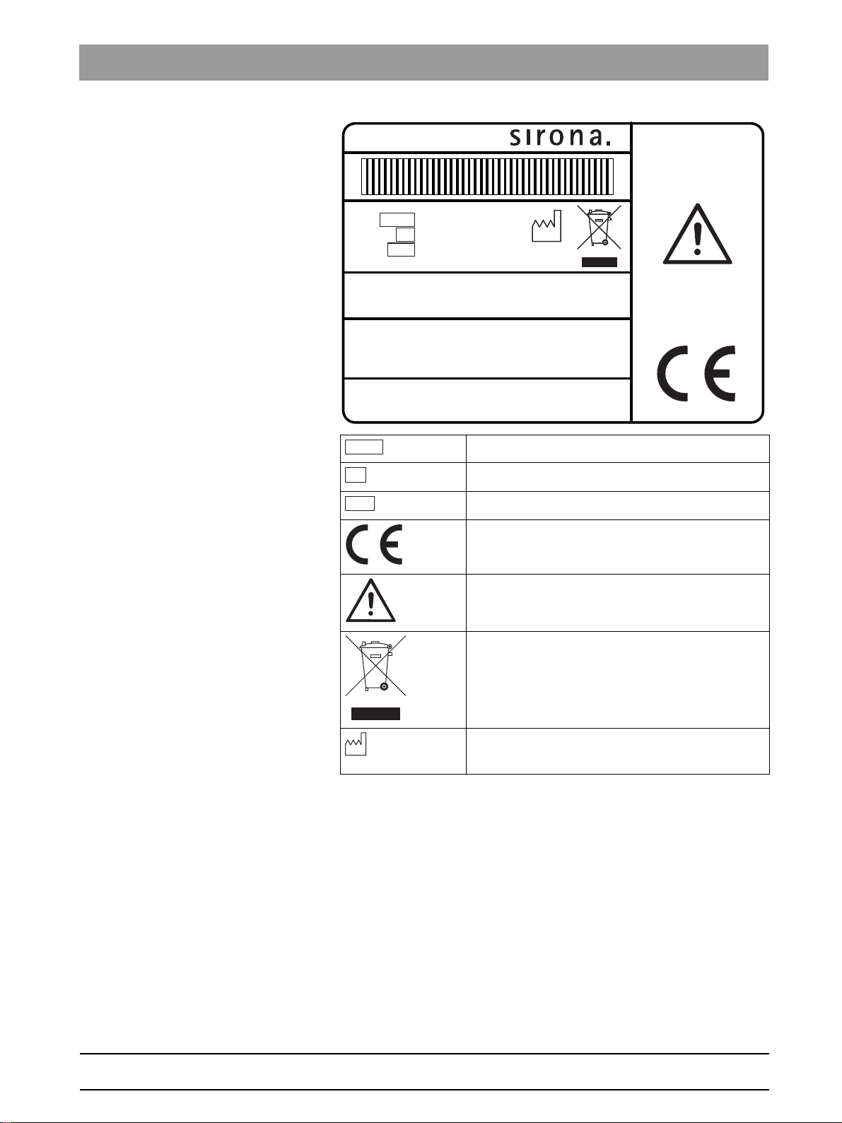
Simulation unit rating plate
SIM MODULAR
Device type
Serial Number
Material number
CE marking
Observe the operating instructions
For disposal information, see the section “Disposal
[ → 210]”
Year of manufacture
bеЦдблЬ
65 64 020 D3650
D3650.201.01.02.02 04.2016
21
Page 22
3Unit description Sirona Dental Systems GmbH
L
M
0
S
A
B
D
C
E
F
I
H
K
G
N
J
3.2System overview Operating Instructions Simulation Unit SIM MODULAR
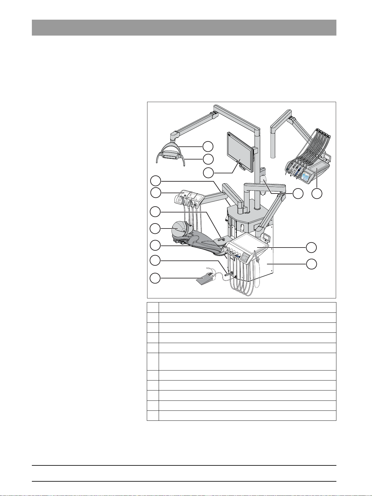
3.2
System overview
The SIM MODULAR simulation workplace comprises the following main
components:
Overview of electric height and tilt adjustment
A LEDview operating light
B Removable handle covers (left/right)
Assistant element
D Clamping lever for dummy head rotation
E Phantom head
F 4-way foot switch and electric height adjustment of the phantom
head
G Electronic foot control
H 22‘‘ AC monitor
I TS dentist element
J CS dentist element with swivel arm
K Supply module
65 64 020 D3650
22 D3650.201.01.02.02 04.2016
Page 23

Sirona Dental Systems GmbH 3Unit description
D
F
A
B
C
E
I
H
G
J
K
Operating Instructions Simulation Unit SIM MODULAR 3.2System overview
L Suction hose connection for suction hose cleaning (see “Suction
hose cleaning with “suction hose cleaning” option [ → 173]”)
M Maintenance flap for accessing the cleaning agent tank to
chemically clean the suction hoses, sediment container or filter
insert for wet suction
N Water bottle system on support tube
Overview of manual height and tilt adjustment
bеЦдблЬ
A LEDview operating light
B Removable handle covers (left/right)
Assistant element
D Clamping lever for dummy head inclination
E Phantom head
F Clamping lever for dummy head rotation
G Foot pedal and manual height adjustment of phantom head
H Supply module
I TS dentist element
J CS dentist element with swivel arm
K Fresh water bottle on support tube
65 64 020 D3650
D3650.201.01.02.02 04.2016
23
Page 24

3Unit description Sirona Dental Systems GmbH
3.3Treatment position LEFT Operating Instructions Simulation Unit SIM MODULAR
3.3
Treatment position LEFT
Treatment position LEFT
1. Pull off the suction hose.
2. Shut down the patient simulator.
3. Raise the dentist element to the highest position and swivel it into
the left-hand position.
4. Swing the assistant element into the right-hand position.
5. Insert the suction hose into the suction socket.
65 64 020 D3650
24 D3650.201.01.02.02 04.2016
Page 25
Sirona Dental Systems GmbH 3Unit description
Operating Instructions Simulation Unit SIM MODULAR 3.4Headrest
3.4
Headrest
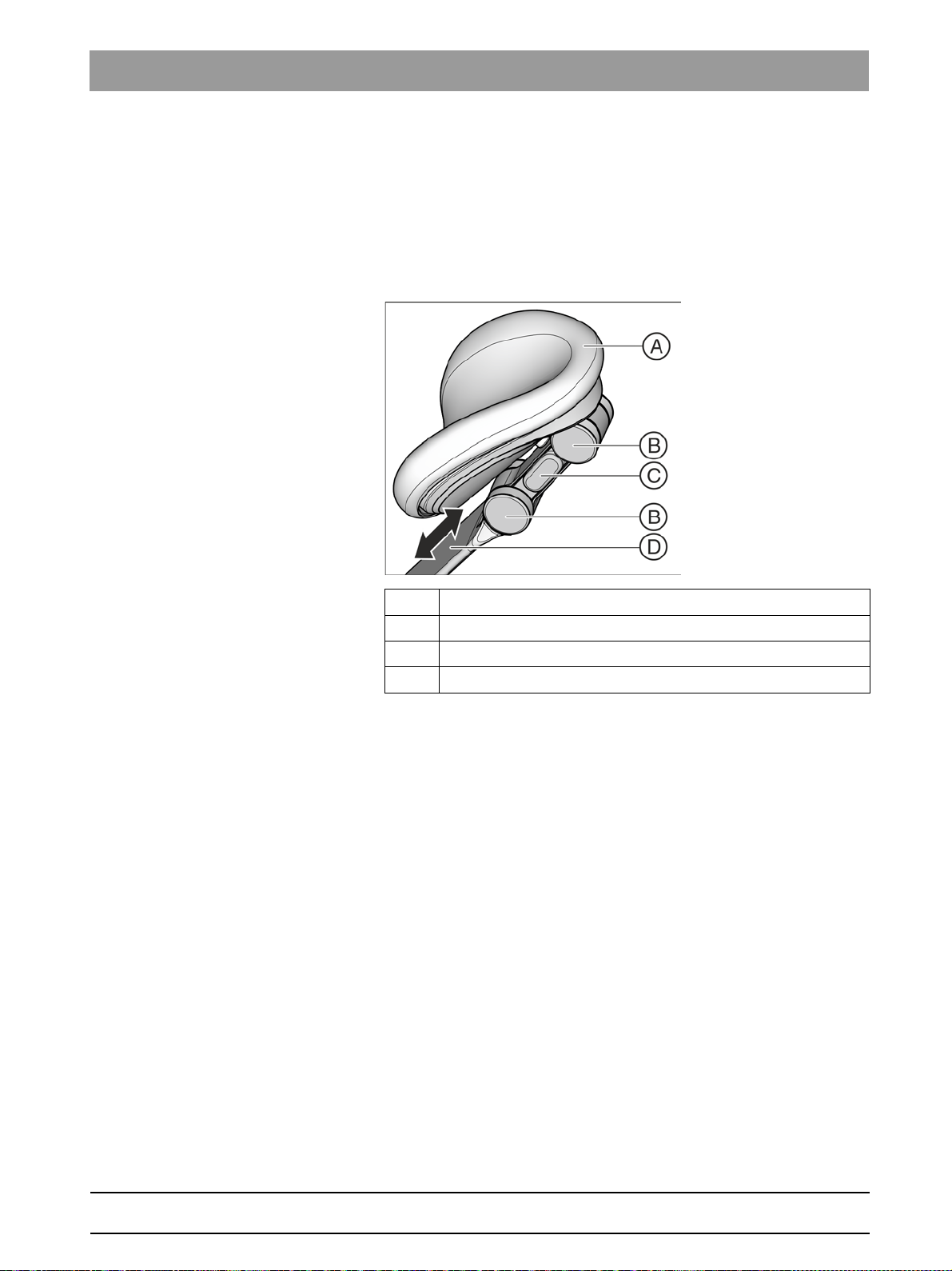
3.4.1 Double-jointed head support
The double articulating headrest is equipped with two rotary joints. They
allow the head inclination to be manually adjusted over a wide range for
maxillary/mandibular treatment. The headrest extension can be pushed
in or pulled out to manually adjust it to the height of the patient.
A Head pad
B Rotary joints
C Unlock button (one-sided)
D Support bar for adjustment to patient height
bеЦдблЬ
For details, see "Adjusting the double articulating headrest."
65 64 020 D3650
D3650.201.01.02.02 04.2016
25
Page 26

3Unit description Sirona Dental Systems GmbH
3.4Headrest Operating Instructions Simulation Unit SIM MODULAR
3.4.2 Adjusting the double articulating headrest
The double articulating headrest is equipped with two rotary joints. They
facilitate manual adjustment of the head inclination for maxillary/
mandibular treatments. The headrest extension can be pushed in or
pulled out manually to adjust it to the height of the patient.
Head support, double-jo int force, holding force
CAUTION
When the lock on the double articulating headrest is released, both
rotary joints lose their holding power.
➢ Place your hands in a way that avoids pinching of your fingers.
➢ Before releasing the headrest, always ensure that both joints are
securely locked!
1. Take hold of them with one hand under the headrest.
2. Use the other hand to press the release button A.
Both rotary joints are now freely movable.
3. Adjust the headrest to the desired treatment position. Then let go of
the release button A.
Both rotary joints lock into place. Ensure that they are securely
positioned! The headrest is secure again.
26 D3650.201.01.02.02 04.2016
65 64 020 D3650
Page 27
Sirona Dental Systems GmbH 3Unit description
D
C
B
A
Operating Instructions Simulation Unit SIM MODULAR 3.5Foot control
3.5
Foot control
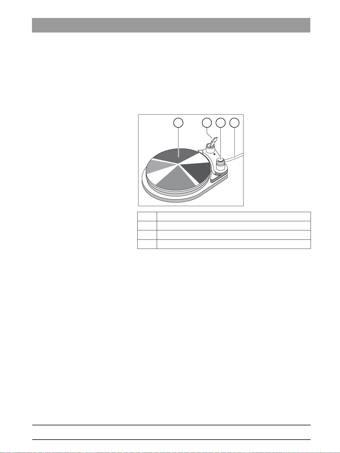
3.5.1 Pneumatic foot switch
With a pneumatic foot switch, the compressed air valve for activating the
high-speed handpieces is integrated into the foot switch. The high-speed
handpieces are therefore continuously adjustable. For electric motors
and the SIROSONIC L scaler, the foot switch is operated as a direct
starter (i.e. at a preset speed and intensity).
A Foot pedal
B Toggle switch for activating spray
C Button for chip blower
D Connecting cable
bеЦдблЬ
65 64 020 D3650
D3650.201.01.02.02 04.2016
27
Page 28
3Unit description Sirona Dental Systems GmbH
F
E
D
C
B
A
S
0
3.5Foot control Operating Instructions Simulation Unit SIM MODULAR
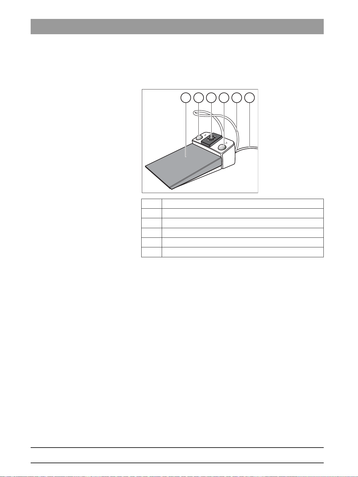
3.5.2 C+ electronic foot switch
The C+ electronic foot control can be set as a speed foot control or direct
starter for electric motors and the SIROSONIC L scaler. The compressed
air for turbines cannot be adjusted.
A Foot pedal
B Left button (spray)
4-way foot switch plate for adjusting the instruments
D Right button (chip blower)
E Positioning bar
F Connecting cable
65 64 020 D3650
28 D3650.201.01.02.02 04.2016
Page 29
Sirona Dental Systems GmbH 3Unit description
Operating Instructions Simulation Unit SIM MODULAR 3.6Dentist element
3.6
Dentist element
SIM MODULAR can be equipped with a TS dentist element (with hanging
hoses) or a CS dentist element (with whip arms). All functions of the
simulation unit can be operated via the control panel on the dentist
element.
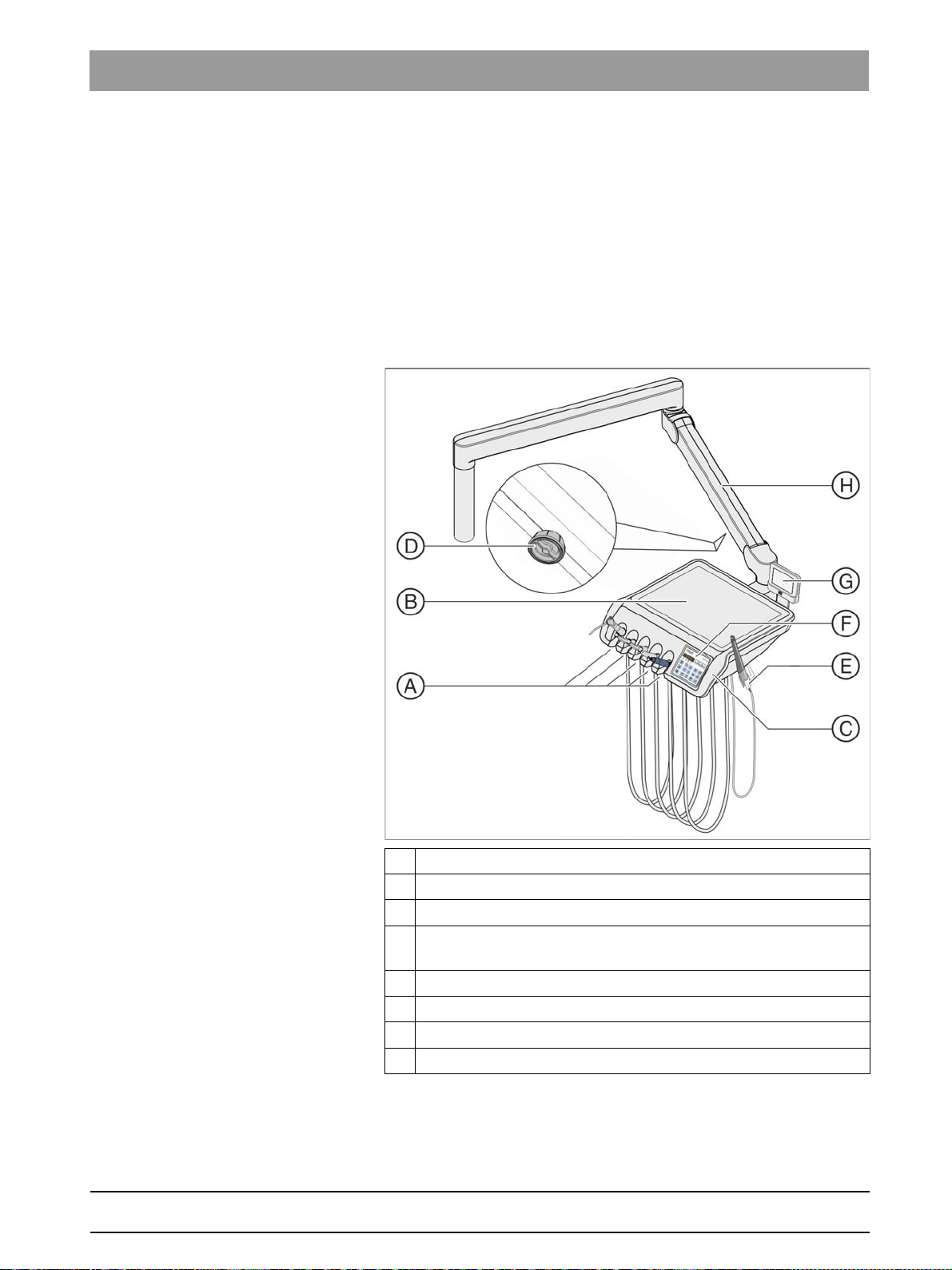
3.6.1 TS dentist element hanging hoses
With this TS dentist element, instruments are placed upright in the
instrument holders. The instrument hoses hang freely under the dentist
element.
bеЦдблЬ
65 64 020 D3650
D3650.201.01.02.02 04.2016
A Optional instrument holder option (max. 5 instruments)
B Optional holder with non-slip silicone mat for 2 standard trays
Optional removable handle covers (left/right)
D Knob to release or tighten the support arm brake for adjusting
height of the dentist element (only on the right)
E Optional additional holder for intraoral camera
F EasyPad (shown here) or EasyTouch user interface
G X-ray viewer option
Support arm
29
Page 30

3Unit description Sirona Dental Systems GmbH
A
F
C
D
B
G
E
H
3.6Dentist element Operating Instructions Simulation Unit SIM MODULAR
3.6.2 CS dentist element with swivel arms
On the CS dentist element, instruments are placed on the instrument
holder horizontally and facing downwards. The instrument hoses are
placed above the dentist element over the whip arms.
A Instrument holder (max. 5 instruments)
B Removable handle covers (left/right)
C Button to release the support arm brake for adjusting height
(left/right)
D EasyPad or EasyTouch user interface
E Holder with non-slip silicone mat
FX-ray viewer
G Whip arms
H Support arm
30 D3650.201.01.02.02 04.2016
65 64 020 D3650
Page 31

Sirona Dental Systems GmbH 3Unit description
Operating Instructions Simulation Unit SIM MODULAR 3.6Dentist element
3.6.3 Instrument positions
The following instrument positions are available:
Holder 1 Holder 2 Holder 3 Holder 4 Holder 5
3-way
syringeStandard
3-way
syringeSPRAYVI
Turbine Turbine Turbine Scaler
SIROSONIC L
Motor BL ISO E
1
Motor BL ISO E1Motor BL ISO E
1
Mini LED curing
light
T E
Scaler
SIROSONIC L
Intraoral
2
cameraSiroCam
F or SiroCam AF
1
The SIM MODULAR simulation unit can be fitted with a maximum of two
motors.
2
A maximum of one SIROSONIC L scaler and one intraoral camera can
be connected.
3
The additional holder for an intraoral camera is only available for the TS
dentist element.
Changes in the instrument positions can be made only by your service
technician.
Additional holder
Intraoral
2
cameraSiroCam
F or SiroCam AF
2
3
2
bеЦдблЬ
65 64 020 D3650
D3650.201.01.02.02 04.2016
31
Page 32

3Unit description Sirona Dental Systems GmbH
B
3.6Dentist element Operating Instructions Simulation Unit SIM MODULAR
3.6.4 Standard EasyPad user interface
3.6.4.1
A EasyPad display
B Status displays
C Fixed keys (membrane keyboard)
D Favorite key pad (membrane keyboard)
EasyPad display and status displays
EasyPad display
For indicating speed, intensity, and torque and for configuring and
servicing the simulation unit. The time, timer function, and error
messages are also displayed.
Status displays
Indicate activation of spray (only for C+ electronic foot switch),
counterclockwise rotation, torque control, and user profile B.
32 D3650.201.01.02.02 04.2016
65 64 020 D3650
Page 33

Sirona Dental Systems GmbH 3Unit description
1
2
Setup
3
A/B
Operating Instructions Simulation Unit SIM MODULAR 3.6Dentist element
3.6.4.2
Fixed keys
Favorite key pad
Resets the speed of the electric motor or intensity of the scaler
For saving the instrument settings speed or intensity, maximum torque if
torque control is activated, and activation of spray (only with C+ electronic
foot control) on function keys 1, 2, and 3.
For custom configuration of the simulation unit by the user, see
Configurating the simulation unit (setup) [ → 136].
Changing other settings, such as purging times.
Operating light
Switches the operating light on, for composite operation, or off.
Composite operation is needed to prevent premature curing of composite
materials. Reduced light intensity < 8000 lux.
With the LEDview when the
operating context
LEDview can be set on the user interface of the treatment center and the
NoTouch sensor.
For details, please refer to the section "Operating light [ → 116]."
Backrest tilt
light intensity
Operating light key
appears. The light intensity of the
is pressed (> 2 s), the
bеЦдблЬ
Moving the patient simulation, see "Tilting backrest".
Height of patient simulator
See "Adjusting the chair height".
Counterclockwise rotation/user profile
With the motor removed: switching counterclockwise rotation on/off, see
"Setting the rotation on the EasyPad" [ → 77].
With instruments in place: changing the user profile, see "Selecting a user
profile".
With motor removed and torque control switched on: Switch the
AutoReverse function on/off when maximum torque is reached by
pressing and holding the key (> 2 s), see "Switching AutoReverse ON/
OFF" [ → 84]. Press briefly (< 2 s) to switch counterclockwise rotation on/
off.
Depending on the context, an ongoing process can be stopped and
switched to the standard operating context, e.g. ending the autopurge
process.
65 64 020 D3650
D3650.201.01.02.02 04.2016
33
Page 34

3Unit description Sirona Dental Systems GmbH
Purge
Clean
Fn
3.6Dentist element Operating Instructions Simulation Unit SIM MODULAR
Endodontics/Purge
With the motor removed: switching the integrated torque control for motor
BL ISO E on/off, see "Switching integrated torque control ON/OFF"
[ → 79]
With the ultrasonic handpiece removed: switching the endo mode on/off
(limiting power), see "Setting the intensity on the EasyPad" [ → 90].
With motor removed and torque control switched on: activating the
calibration process (> 2 s), see "Calibrating the burr drive" [ → 80]
With instruments in place: selecting the purge, autopurge, sanitize, and
stand-alone water supply functions
Display mode/clean
Display mode/clean
With motor removed and torque control switched on: Switching between
torque and speed display, see “Setting the speed” [ → 83] in the section
“Integrated speed control”.
With instruments in place: Deactivates the complete user interface of the
dentist element. The instruments of the dentist and assistant elements
can no longer be activated. The SIVISION monitor and the camera
system are switched off. Pressing it again > 3 s reactivates the simulation
unit. This is used to clean the surface and protect against interference
from an external HF surgical unit so that no unwanted functions can be
accidentally triggered, see “Disinfecting user interfaces”. Electromagnetic
interference can often be reduced, if the external HF surgical unit is
operated with a neutral electrode.
Function key
Starts and stops timer, see "Timer function".
34 D3650.201.01.02.02 04.2016
65 64 020 D3650
Page 35
Sirona Dental Systems GmbH 3Unit description
INTEGO
A
10:45:03
2
1
0S
A
B
Clean
Operating Instructions Simulation Unit SIM MODULAR 3.6Dentist element
3.6.5 Comfort EasyTouch user interface
The EasyTouch option is available only for the SIM MODULAR simulation
unit.
bеЦдблЬ
A Touchscreen (pressure-sensitive user interface)
B Fixed keys (membrane keyboard)
65 64 020 D3650
D3650.201.01.02.02 04.2016
35
Page 36

3Unit description Sirona Dental Systems GmbH
B
10:45:03
2
1
0S
B
10:45:03
2
1
0S
rpm
20000
1.2 4020
Set
3.6Dentist element Operating Instructions Simulation Unit SIM MODULAR
3.6.5.1
Start dialog After the simulation unit is switched on, the start program automatically
Instrument program The Instrument program that corresponds to the instrument removed
Touch screen
The touchscreen displays virtual function keys according to the program
selected. A list of all function keys is provided in the Appendix of this
document, see "Overview of all function keys".
Some programs are divided into main programs and sub-screens. The
main programs are briefly introduced below:
appears. The start program displays the function keys for the patient
simulator adjustment and other general functions.
from the holder is displayed on the touchscreen (for example, motor).
36 D3650.201.01.02.02 04.2016
65 64 020 D3650
Page 37

Sirona Dental Systems GmbH 3Unit description
Operating Instructions Simulation Unit SIM MODULAR 3.6Dentist element
SIVISION program The SIVISION program enables certain computer programs running on
the PC to be controlled directly from the simulation unit. For details, see
"Operation with a PC".
bеЦдблЬ
65 64 020 D3650
D3650.201.01.02.02 04.2016
37
Page 38

3Unit description Sirona Dental Systems GmbH
Clean
3.6Dentist element Operating Instructions Simulation Unit SIM MODULAR
3.6.5.2
Fixed keys of the EasyTouch user interface
Clean key
Pressing this key deactivates the complete user interface of the dentist
element. Pressing it again > 3 s reactivates the user interface.
Deactivates the complete user interface of the dentist element. The
instruments of the dentist and assistant elements can no longer be
activated. The SIVISION monitor and the camera system are switched
off. Pressing it again (>3 s) reactivates the simulation unit. This is used to
make sure that no unwanted functions are accidentally triggered while
cleaning the surface and protect from interference from an external HF
device (see Disinfect user interfaces [ → 151]). Electromagnetic
interference can often be reduced if the external HF surgical device is
operated with a neutral electrode.
Operating light
Switches the operating light on, for composite operation, or off.
Composite operation is needed to prevent premature curing of composite
materials. Reduced light intensity < 8000 lux.
With the LEDview when the
operating context
light intensity
Operating light key
appears. The light intensity of the
LEDview can be set on the user interface of the treatment center and the
NoTouch sensor.
is pressed (> 2 s), the
For details, please refer to the section "Operating light [ → 116]."
Sub-screen
Some programs are divided into a main program and sub-screens.
Only function keys for the basic functions are displayed in the main
dialogs. The
Sub-dialog
key (two rectangles) leads to further setting
possibilities.
38 D3650.201.01.02.02 04.2016
65 64 020 D3650
Page 39

Sirona Dental Systems GmbH 3Unit description
Operating Instructions Simulation Unit SIM MODULAR 3.7Assistant element
3.7
Assistant element
The scope of functions of the assistant element is adapted to the dental
assistant's field of activity.
The SIM MODULAR simulation unit can be equipped with the comfort
assistant element. The user interface on the assistant element is optional.
Comfort assistant element
The Comfort assistant element is attached to the supply module by a
support arm. It can also be positioned to allow unassisted treatment by
the dentist.
bеЦдблЬ
65 64 020 D3650
D3650.201.01.02.02 04.2016
A Holders 1 to 4 (from left to right) for instruments
B User interface (optional)
Handle
D Tray area with optional silicone mat
E Cocer for the central suction sieve
F Support arm
G 3 rotary joints for flexible positioning
39
Page 40

3Unit description Sirona Dental Systems GmbH
3.7Assistant element Operating Instructions Simulation Unit SIM MODULAR
3.7.1 Instrument positions
Instrument positions
The following instrument positions are available:
Holder 1 Holder 2 Holder 3 Holder 4
3-way syringeSPRAYVIT E
additional spray aspirator
3-way syringeStandard Polymerization light
Mini L.E.D.
1
Intraoral cameraSiroCam F
or SiroCam AF
1
1
Either a MINI LED curing light, an intraoral camera or an additional
spray aspirator can be connected to the simulation unit.
Changes to instrument holder 2 can be made only by your service
technician.
1
Spray aspirator Saliva ejector
40 D3650.201.01.02.02 04.2016
65 64 020 D3650
Page 41

Sirona Dental Systems GmbH 4Operation
Operating Instructions Simulation Unit SIM MODULAR 4.1Putting the simulation unit into operation
Operation
4
Adjusting the height
4.1
Putting the simulation unit into operation
4.1.1 Initial Operation
Switch on the main switch (I).
The display on the dentist element lights up.
CAUTION
For safety reasons, always switch the SIM MODULAR simulation
workstation off (O) after completing work.
Electric height and tilt adjustment
The patient simulation can be moved up and down using buttons (A) and
(B) on the user interface on the dentist element or using the 4-way foot
switch.
CAUTION
bеЦдблЬ
Adjusting the inclination and rotation
Risk of getting crushed/trapped!
When adjusting the height, it is very important to ensure that there are
no people or objects in the immediate vicinity of the patient simulator!
IMPORTANT
If the facility for adjusting the height of the patient simulator gets stuck
in the end position and will not move in the opposite direction, you
should immediately contact an after-sales service organization that has
been approved by Sirona.
1. Release the clamping lever.
2. Move the patient simulator to the desired position.
3. Tighten the clamping lever.
65 64 020 D3650
D3650.201.01.02.02 04.2016
41
Page 42
4Operation Sirona Dental Systems GmbH
4.1Putting the simulation unit into operation Operating Instructions Simulation Unit SIM MODULAR
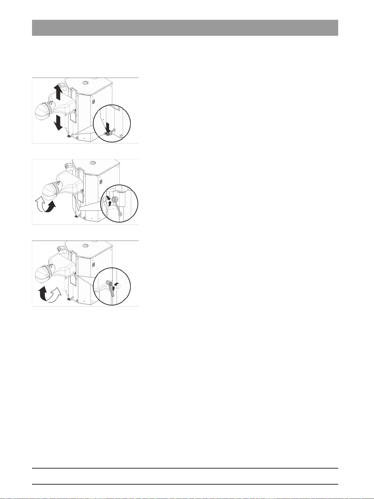
Manual height and inclination adjustment
Adjusting the height
Press the foot pedal to manually move the patient simulator up and down.
Adjusting the rotation
1. Release the rotation clamping lever.
2. Move the patient simulator to the desired position.
3. Tighten the clamping lever.
Adjusting the inclination
1. Release the clamping lever.
2. Move the patient simulator to the desired position.
3. Tighten the clamping lever.
42 D3650.201.01.02.02 04.2016
65 64 020 D3650
Page 43

Sirona Dental Systems GmbH 4Operation
B
A/B
B
10:45:03
A
B
10:45:03
2
1
0S
Operating Instructions Simulation Unit SIM MODULAR 4.1Putting the simulation unit into operation
4.1.2 Selecting a user profile
If your simulation unit is equipped with the EasyPad standard user
interface, it can manage up to two user profiles. The EasyTouch comfort
user interface can manage up to four user profiles. This way, multiple
users can operate the simulation unit without having to forego their own
individual treatment and operation related settings.
The following is stored in the user profiles:
● For configurations in the setup, see Configurating the simulation unit
(setup) [ → 136]
● For settings in the operating contexts and screens on the
instruments, see Saving instrument settings [ → 65]
● Configuration of the SIVISION screen for PC control. The
configuration is saved in the PC application SIUCOM plus that is
installed on the PC.
When the user profile is selected, the preset configurations and settings
become available.
Selecting a user profile on the EasyPad
If the status display
is does not light up, user profile A. The user profile used last is
automatically loaded when the simulation unit is switched on.
user profile
lights up, user profile B is pre-selected; if
bеЦдблЬ
✔ All instruments are placed in the holders.
➢ Press the
The status display
Counterclockwise rotation / User profile
User profile
between the user profiles.
lights up or turns off. This switches
Selecting a user profile on the EasyTouch
The user profiles A are distinguished with the letters A to D. The active
user profile, here B, is displayed in the status field of the touchscreen. If
only one user profile is set up, nothing is displayed. The user profile used
last is automatically loaded when the simulation unit is switched on.
✔ The
➢ Touch the
On the EasyTouch user interface, if any of the user profiles are not
required, their number can be limited, see "Preselecting the number of
user profiles".
Start dialog
profile is selected.
The user profile displayed in the status field is active.
is displayed on the touchscreen.
User profile
as often as necessary until the desired user
key.
65 64 020 D3650
D3650.201.01.02.02 04.2016
43
Page 44

4Operation Sirona Dental Systems GmbH
B
1
2
Setup
3
A/B
4.2Concept of the user interface Operating Instructions Simulation Unit SIM MODULAR
4.2
Concept of the user interface
4.2.1 Standard EasyPad user interface
EasyPad displays
The EasyPad user interface is equipped with seven-segment displays.
Five digits or letters can appear on the display. Depending on the
operating context, they are used to display speed, intensity, and torque
and for configuration and maintenance of the simulation unit. The time,
timer function, and error messages are also displayed.
Ongoing processes such as flushing the instruments with the purge
function, the waiting period for sanitizing, or calibration of the burr drive
for integrated torque control are displayed in the EasyPad display with a
revolving element at the end of the line.
If two elements at the end of the EasyPad display blink alternately, action
is required by the user, e.g. disinfectant or water must be refilled.
For information about the display of errors messages, please refer to
"Easy Pad error messages".
Status displays
There are status lights below the EasyPad displays. They indicate
activation of spray (only for C+ electronic foot switch), counterclockwise
rotation, torque control, and user profile B.
Favorite key pad
These fixed keys serve to:
● Adjust the speed of the electric motor or the intensity of the
SIROSONIC L scaler
● Save and access the following instrument settings on function keys
1, 2, and 3:
– Speed or intensity
– Maximum torque with torque control activated
– Activating spray (only with C+ electronic foot switch)
● Access setup and browse through setup settings
● Change other adjustment values, e.g. purging time
Dual use of fixed keys
Depending on the operating context, and whether instruments are
removed or placed in the holder or torque control is switched on, different
functions can be assigned to the fixed keys. For example the
Counterclockwise rotation / User profile
[ → 33].
button, see also Fixed keys
44 D3650.201.01.02.02 04.2016
65 64 020 D3650
Page 45

Sirona Dental Systems GmbH 4Operation
Purge
Clean
A/B
Operating Instructions Simulation Unit SIM MODULAR 4.2Concept of the user interface
Fixed keys without a function
Fixed keys for functions not included with the simulation unit have no
function on the user interface. This applies only to keys with dual
functions for the options of integrated torque control:
The integrated torque control cannot be activated in this case.
Toggling between speed and torque display is not possible.
Accessing functions
Functions are triggered using the fixed keys on the user interface.
By pressing and holding the Tumbler filling and Flushing keys (> 2 s), the
setting context can be accessed.
Stopping processes
Depending on the operating context, you can use the
rotation/User profile
Touching it again switches to the standard operating context.
key to terminate a process that is in progress.
Counterclockwise
bеЦдблЬ
65 64 020 D3650
D3650.201.01.02.02 04.2016
45
Page 46
4Operation Sirona Dental Systems GmbH
B
10:45:03
2
1
0S
2 2
S
40
4.2Concept of the user interface Operating Instructions Simulation Unit SIM MODULAR
4.2.2 Comfort EasyTouch user interface
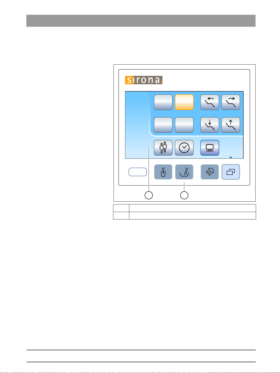
4.2.2.1
Virtual function keys
The touchscreen displays virtual function keys according to the program
selected. Required functions can be activated either by touching the
function keys with your finger or via the cursor with the foot switch.
Missing function keys
The adjacent illustration shows the touchscreen of a simulation unit as
supplied to the customer with all features.
Function keys for functions not included with the simulation unit are not
displayed on the touchscreen. Additionally, the touchscreen user
interface may vary due to individual setup settings, see Configurating the
simulation unit (setup) [ → 136].
Start dialog
In the
"Network interface".
Furthermore, in the
the setup setting "Preselect the number of user profiles".
this refers to the function key for the feature option
Start dialog
the
User profile
key can be hidden with
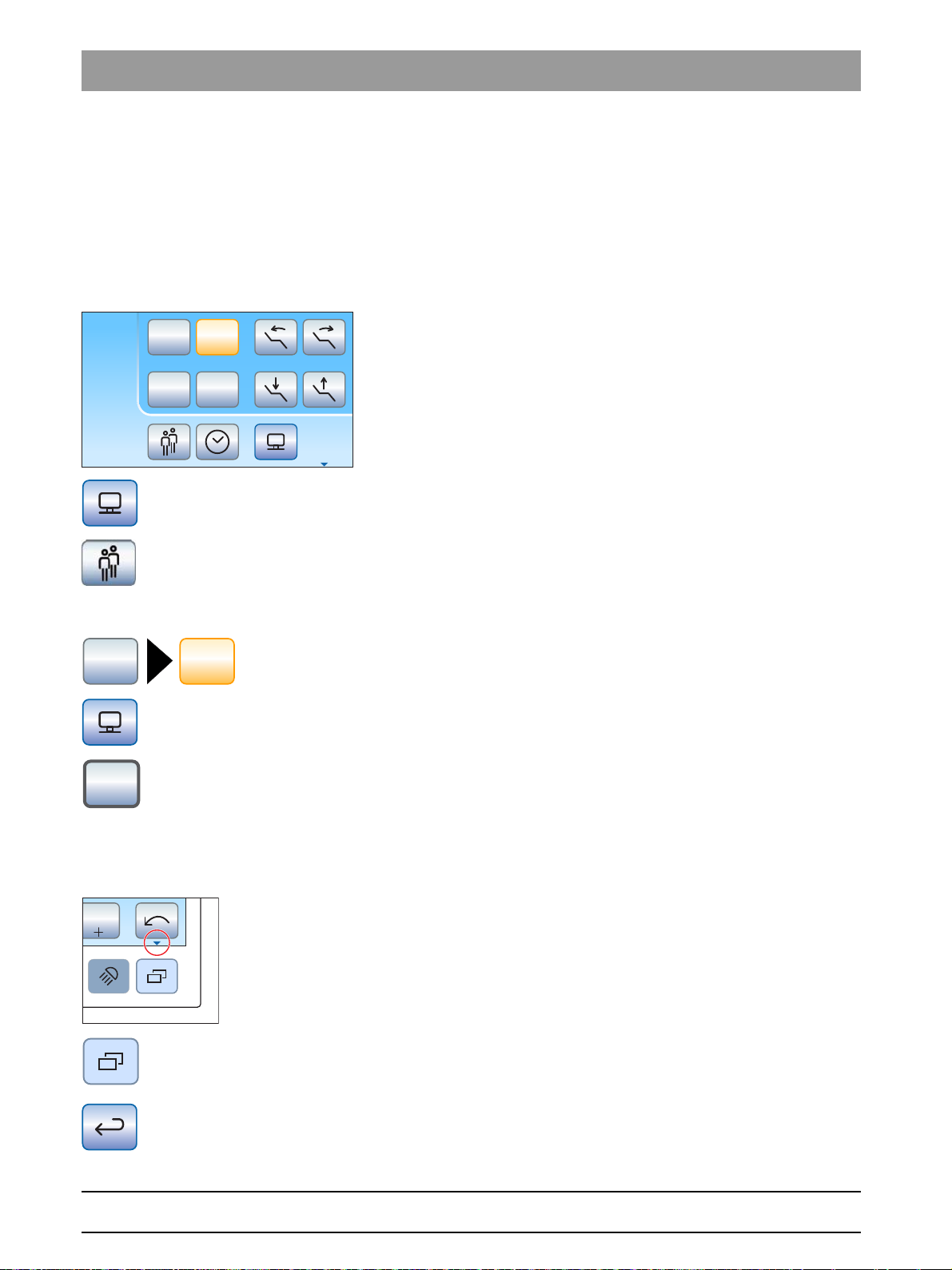
Key background color
General functions are represented by gray keys. If the corresponding
function is switched on or active, the key is displayed in orange.
Keys that initiate a dialog change or lead to sub-dialogs and settings
dialogs are displayed blue.
As long as a key remains activated, its active state is marked by a bold
black border.
4.2.2.2
Sub-screens and settings screens
Sub-screens
Some programs are divided into a main program and sub-screens. This
is indicated by a small arrow at the bottom right of the touchscreen. It
points to the fixed key
Only function keys for the basic functions are displayed in the main
dialogs. The
options.
Sub-screens usually are generally hidden automatically after a certain
period has elapsed. The
sub-screen immediately.
Sub-dialog
Sub-screen
key (two rectangles) leads to more setting
Return
below the touchscreen.
key (return arrow) closes the opened
46 D3650.201.01.02.02 04.2016
65 64 020 D3650
Page 47

Sirona Dental Systems GmbH 4Operation
B
10:45:03
2
1
0S
S
B
10:45:03
!
San
1d
Amalg
Desinf
41d
chem
A
Operating Instructions Simulation Unit SIM MODULAR 4.2Concept of the user interface
Settings screens
In many cases, functions not only can be switched on or off, but also can
be set. If a function key is pressed and held (> 2 s), the corresponding
settings screen appears. This screen is superimposed on the current
screen. The dialog in the background has a semitransparent appearance
and is temporarily disabled for inputs.
Settings screens are usually automatically hidden after a certain period
Return
has elapsed. The
screen immediately.
key (return arrow) closes the opened settings
4.2.2.3
Status column
There is a column for status displays at the left edge of the touchscreen.
Here the current time with the seconds below is shown and if several user
profiles A are preselected, the active user profile A to D is also displayed.
In addition, the days until the next sanitation and maintenance or status
messages such as add disinfectant, refill the cleaning agent for chemical
cleaning of suction hoses, or error messages are displayed.
bеЦдблЬ
65 64 020 D3650
D3650.201.01.02.02 04.2016
47
Page 48

4Operation Sirona Dental Systems GmbH
4.3Foot control Operating Instructions Simulation Unit SIM MODULAR
4.3
Foot control
The simulation unit can be operated with a pneumatic foot control or the
C+ electronic foot control.
4.3.1 Pneumatic foot switch
When the instrument is removed from the holder, the speed or intensity
are automatically displayed on the EasyPad. On the EasyTouch, the
instrument dialog is called up.
Foot pedal
➢ Remove an instrument (electric motor, highspeed handpiece/air
motor, SIROSONIC L) and step on the foot pedal.
The instrument is switched on with the set speed and intensity.
For highspeed handpieces/air motors, the speed is controlled by
the pedal action.
Spray switch
➢ Move the toggle switch.
Left position: Spray off
Right position: Spray on
The spray is either switched on or off when an instrument is
activated.
Chip blower
With the chip blower, an air jet comes out of the burr instrument.
➢ Remove an instrument and press on the right button.
The chip blower remains switched on as long as the button is
pressed.
48 D3650.201.01.02.02 04.2016
65 64 020 D3650
Page 49

Sirona Dental Systems GmbH 4Operation
S
0
S
0
S
S
0
0
Operating Instructions Simulation Unit SIM MODULAR 4.3Foot control
4.3.2 C+ electronic foot switch
The C+ electronic foot switch operating elements are assigned different
functions depending on whether the instruments are all in place or an
instrument is removed from its holder.
When an instrument is removed from the holder, the last speed or
intensity settings are automatically displayed on the EasyPad. On the
EasyTouch, the instrument dialog is called up. If the intraoral camera is
removed, the SIVISION dialog appears.
Foot pedal
✔ All instruments are in place.
➢ Press the foot pedal.
The EasyPad switches to the standard operating context (initial
situation), the EasyTouch displays the start dialog.
✔ An instrument is removed.
➢ Step on the foot pedal.
The instrument is activated. With the EasyPad, the motor and the
SIROSONIC L are activated with the set speed or intensity (direct
starter). When the speed control foot switch function is set on the
EasyTouch, the motor and SIROSONIC L can be controlled
depending on the pedal position, see "Set C+ electronic foot
switch as direct starter or speed control foot switch" [ → 64]. When
the intraoral camera is removed from the holder, the camera
image focuses and the display switches to the still or live image.
bеЦдблЬ
Left button
✔ An instrument is removed.
➢ Press the left button.
With the EasyPad the spray is switched on and off, with the
EasyTouch the preset cooling medium in the sub-dialog (spray or
air). If the intraoral camera is removed, the video still image is
saved in SIDEXIS; the live image is displayed in the next
quadrant in SI Video.
Right button
✔ An instrument is removed.
➢ Press the right button.
The chip blower remains switched on as long as the button is
pressed. When the intraoral camera is removed, it is possible to
toggle between single image and quad image in SI Video.
65 64 020 D3650
D3650.201.01.02.02 04.2016
49
Page 50

4Operation Sirona Dental Systems GmbH
S
0
1
2
Setup
3
S
0
1.2 4020
Set
S
0
4.3Foot control Operating Instructions Simulation Unit SIM MODULAR
4-way foot control plate
✔ An electric motor or the SIROSONIC L is removed.
➢ Slide the 4-way foot switch plate up or down.
Up: The speed or intensity is increased.
Down: The speed or intensity is reduced.
✔ An electric motor or the SIROSONIC L is removed.
➢ Slide the 4-way foot switch plate to the right.
The instrument settings saved for the favorite key, e.g. speed,
intensity and activation of spray are called up.
✔ An electric motor is removed.
➢ Slide the 4-way foot switch plate to the left.
The clockwise/counterclockwise rotation of the electric motor is
activated.
Foot switch, functions during activ e treatment
IMPORTANT
The allocation of functions may differ when torque control is active.
➢ When torque control is activated, follow the directions for operating
the foot switch, see "Integrated torque control".
50 D3650.201.01.02.02 04.2016
65 64 020 D3650
Page 51

Sirona Dental Systems GmbH 4Operation
S 0
2
1
0
S
2
1
S 0
S
0
0
S
S
0
Operating Instructions Simulation Unit SIM MODULAR 4.4Simulation unit
4.4
Simulation unit
4.4.1 Triggering an immediate movement stop
➢ Touch one of the patient simulator keys on the EasyPad or
EasyTouch.
➢ Press one of the patient simulator keys on the control panel of the
assistant element.
Triggering movement stop on the pn eu ma ti c foot switch
➢ Press the pedal of the pneumatic foot switch.
bеЦдблЬ
➢ With all instruments are in place, press the pedal or the left or right
button of the C+ electronic foot switch.
➢ With an instrument removed from the holder, press the pedal of the
C+ electronic foot switch.
➢ Move the 4-way switch plate on the C+ electronic foot switch in any
direction.
➢ Move the 4-way foot switch in any direction.
65 64 020 D3650
D3650.201.01.02.02 04.2016
51
Page 52

4Operation Sirona Dental Systems GmbH
4.4Simulation unit Operating Instructions Simulation Unit SIM MODULAR
4.4.2 Manually moving the patient simulator
Dentist element on support arm, collision, manual movement
WARNING
The dentist element could be positioned within the movement range of
the patient simulator.
➢ Before moving the patient simulator, position the dentist element to
make a collision impossible.
52 D3650.201.01.02.02 04.2016
65 64 020 D3650
Page 53

Sirona Dental Systems GmbH 4Operation
max.
1 kg
2.2 lbs
+
max.
1 kg
2.2 lbs
max.
2,0 kg
4.4 lbs
max.
2,0 kg
4.4 lbs
max.
2,0 kg
4.4 lbs
max.
1 kg
2.2 lbs
max.
0,5 kg
1.1 lbs
max.
1,5 kg
3.3 lbs
max.
1,5 kg
3.3 lbs
+
max.
1 kg
2.2 lbs
max.
1,5 kg
3.3 lbs
max.
0,5 kg
1.1 lbs
Operating Instructions Simulation Unit SIM MODULAR 4.5Dentist element
4.5
Dentist element
4.5.1 Maximum load capacity
TS dentist element
The maximum load on the TS dentist element without a tray holder is 1 kg
(2.2 lbs).
The TS dentist element can be equipped with a tray holder mounted on
the left side of the dentist element. The holder has room for two standard
trays.
The maximum load on the TS dentist element with a tray holder is 2 kg
(4.4 lbs). In this case, the maximum load on the dentist element and the
tray is 1 kg (2.2 lbs) each.
bеЦдблЬ
65 64 020 D3650
D3650.201.01.02.02 04.2016
CS dentist element
The maximum load on the CS dentist element without a tray holder is 0.5
kg (1.1 lbs).
The CS dentist element can be equipped with a tray holder mounted
below the dentist element. The holder is available in two sizes for one or
two standard trays.
The maximum load on the CS dentist element with a tray holder is 1.5 kg
(3.3 lbs). In this case, the maximum load on the dentist element is 0.5 kg
(1.1 lbs) and on the tray 1 kg (2.2 lbs).
53
Page 54

4Operation Sirona Dental Systems GmbH
4.5Dentist element Operating Instructions Simulation Unit SIM MODULAR
Removing the tray
1. Hold the tray tightly.
2. Open the lock by turning the lever downwards.
3. Remove the tray.
4. Let the lever fall back into its original position.
To insert the tray, simply guide it into the mount. The mechanism locks
automatically.
Tray, Tray Holde r
CAUTION
If the tray is not locked in place, it can disengage from the tray holder.
➢ After installing the tray, make sure it is securely attached to the tray
holder.
54 D3650.201.01.02.02 04.2016
65 64 020 D3650
Page 55

Sirona Dental Systems GmbH 4Operation
Operating Instructions Simulation Unit SIM MODULAR 4.5Dentist element
4.5.2 Positioning the dentist element
Dentist element on supp ort arm, collision, manua l movement
WARNING
It is possible to position the dentist element in the operating area of the
user.
Moving the patient simulator can result in collision with the dentist
element or its support arm. There is the danger of injury due to crushing.
➢ Before moving the patient simulator, position the dentist element to
make a collision impossible.
Dentist element, sudden move me nts
NOTICE
Sudden movements can cause instruments to fall out of the holder in the
dentist element.
➢ Try to avoid sudden movements of the dentist element.
The dentist element is attached to the simulation unit with a flexible
support arm. The dentist element is held in place at the adjusted height
with a pneumatic locking brake in the support arm.
The hand knob to adjust the support arm brake is underneath the flexible
support arm.
The knob must only be adjusted if required.
➢ Hold the hand knob in your hand and turn it counterclockwise to
release the brake, or clockwise to tighten the brake.
There is a push button near the two handles on the sides of the CS dentist
element to release the brake. The TS dentist element only has one button
on the right side.
The button must only be pressed to move the chair vertically. Horizontal
movements are also possible without releasing the brake.
1. Grip a handle with your hand and keep the button pressed.
The locking brake is released with the sound of pressurized air.
The dentist element can be raised and lowered.
2. Position the dentist element and release the button.
The dentist element is secured at the height set.
Depending on the equipment of the dentist element, the retention force of
the locking brake can be changed by the technician.
bеЦдблЬ
65 64 020 D3650
D3650.201.01.02.02 04.2016
55
Page 56

4Operation Sirona Dental Systems GmbH
0
S
0
S
4.5Dentist element Operating Instructions Simulation Unit SIM MODULAR
Positioning the TS dentist element (standard position)
In the standard position, the support arm of the TS dentist element is
attached to the front mount of the supply module.
Positioning the CS dentist element (standard position)
In the standard position, the support arm of the CS dentist element is
attached to the front mount of the supply module.
4.5.3 Fixed keys on the dentist element
An overview of the fixed keys on the EasyPad and EasyTouch can be
found in the Description of Device, see "EasyPad standard user interface"
[ → 32] and "EasyTouch comfort user interface".
56 D3650.201.01.02.02 04.2016
65 64 020 D3650
Page 57

Sirona Dental Systems GmbH 4Operation
Operating Instructions Simulation Unit SIM MODULAR 4.5Dentist element
4.5.4 Placing the instruments in their holders
Automatic opening of instrument dialogs
On the EasyPad, the speed or intensity is shown automatically on the
display depending on which instrument is removed from the holder. On
the EasyTouch, the respective instrument program appears on the
touchscreen.
If more than one instrument is removed from the holder, the speed or
intensity or instrument dialog of the instrument removed first is displayed.
Therefore, always ensure that all instruments are placed in the correct
instrument holders. If any instruments are placed in the wrong holders,
the wrong instrument dialog will be opened when they are removed from
the holders.
Cover for TS dentist element
Cover
A cover can be purchased as an accessory for an instrument holder
which is not used.
Insert the cover into an unassigned instrument holder. This prevents
accidental deposit of an instrument in this holder.
To reorder the cover, see “Spare parts and consumables”.
Instrument hoses
NOTICE
The instrument hoses contain electrical cables and media pipes.
Over-tensioning or pinching the hoses may cause the electrical cables
to break and the media pipes to leak.
➢ Ensure that you do not pull or bend the instrument hoses too much.
bеЦдблЬ
65 64 020 D3650
D3650.201.01.02.02 04.2016
57
Page 58

4Operation Sirona Dental Systems GmbH
A
4.5Dentist element Operating Instructions Simulation Unit SIM MODULAR
Swivel arm on CS dentist element
Spring elements in the dentist element pull the whip arm back into its
original position, preventing instrument hoses from hanging down.
➢ Remove the required instrument from its holder and pull it toward you.
The swivel arm is pulled forward along the instrument hose. On
the EasyPad, the speed or intensity of the respective instrument
is shown on the display; with the EasyTouch, the instrument
dialog appears on the touchscreen. The instrument can be
activated via the foot control.
The positions of the instruments on the holder can be optimized by
moving the guide rollers A on the whip arms.
Holder on the CS dentist element
Dentist element with swivel ar ms, penetration of fluids
NOTICE
Fluids can enter the dentist element through the openings in the swivel
arm.
This can damage the electronics in the dentist element.
➢ Do not place any liquids on the CS dentist element.
58 D3650.201.01.02.02 04.2016
65 64 020 D3650
Page 59

Sirona Dental Systems GmbH 4Operation
Operating Instructions Simulation Unit SIM MODULAR 4.5Dentist element
4.5.5 X-ray image viewer
The TS and CS dentist elements can be equipped with an X-ray viewer.
The ON/OFF switch is on the X-ray viewer. It switches off automatically
after 10 minutes.
If the simulation unit does not have an X-ray viewer, but is equipped with
Start
a SIVISION monitor, it can be switched to a white screen in the
screen. The white screen function is available only with the EasyTouch.
Monitor, not suitable for di agnosis
sub-
WARNING
Faulty diagnoses may be possible for X-ray images
Use the white screen of the SIVISION monitor not for diagnosis of X-ray
images. The light intensity of the monitor is not sufficient.
bеЦдблЬ
65 64 020 D3650
D3650.201.01.02.02 04.2016
59
Page 60

4Operation Sirona Dental Systems GmbH
4.5Dentist element Operating Instructions Simulation Unit SIM MODULAR
4.5.6 General instrument functions
EasyPad
Settings for the coolant, instrument light, and foot switch can be made for
the instrument removed from the holder.
EasyTouch
Settings for the coolant, instrument light, and foot switch can be made in
the sub-screen of the instrument removed from the holder.
The sub-screens vary according to the instrument removed. Functions
not available for the respective instrument are not displayed in the subscreen.
4.5.6.1
Instrument functions on the EasyPad
4.5.6.1.1 Switching spray ON/OFF
The spray is switched on when the foot switch is activated in combination
with the instrument. On the EasyPad, the spray is switched on/off via the
foot switch.
Cooling of treatment are as
CAUTION
Instrument can be operated without coolant.
Tooth substance can be damaged by frictional heat.
➢ Always make sure that the treatment area does not overheat
whenever you switch the coolant off.
Flow rate reduced
CAUTION
If air and water are taken from an external connection, the flow rate in
the instruments can drop.
Tooth substance can be damaged by frictional heat.
➢ Avoid the removal of water from additional devices during treatment
with treatment center instruments.
Switch spray on/off with the pneumatic foot switch
With a pneumatic foot switch
➢ Toggle the switch on the pneumatic foot switch.
Left position: Spray off
Right position: Spray on
The spray is switched on/off when the instrument is activated.
Activation of the spray is not displayed on the EasyPad when a pneumatic
foot switch is used. The status display
Spray
does not light up.
65 64 020 D3650
60 D3650.201.01.02.02 04.2016
Page 61

Sirona Dental Systems GmbH 4Operation
S
0
S
B
S
0
0
Operating Instructions Simulation Unit SIM MODULAR 4.5Dentist element
On the C+ electronic foot switch
✔ An instrument is removed from the holder.
➢ Press the left button of the C+ electronic foot switch.
Spray
When the status display
lights up on the EasyPad, spray is
switched on when the instrument is activated.
Activation of the spray is saved on the favorite keys, see section "Setting
the speed on the EasyPad" [ → 73], "Setting the intensity on the EasyPad"
[ → 90] and "Integrated torque control on the EasyPad" [ → 79].
4.5.6.1.2 Activating the chip blower
With the chip blower, an air jet comes out of the burr instrument nozzle.
✔ A highspeed handpiece or motor is removed from the holder.
➢ Press the right button of the pneumatic or C+ electronic foot switch.
The chip blower remains switched on as long as the button is
pressed.
bеЦдблЬ
65 64 020 D3650
D3650.201.01.02.02 04.2016
61
Page 62

4Operation Sirona Dental Systems GmbH
Auto
Rev
Apex
Stop
Apex Dist
4.5Dentist element Operating Instructions Simulation Unit SIM MODULAR
4.5.6.2
Instrument functions on the EasyTouch
4.5.6.2.1 Opening the sub-screen
✔ An instrument is removed from the holder.
✔ The
1. Press the
2. To get to the second sub-screen, press the
Instrument program
the touchscreen.
Sub-dialog
The sub-screen is displayed.
again.
The second sub-dialog is displayed.
of the removed instrument is displayed on
fixed key.
Sub-dialog
fixed key
4.5.6.2.2 Switch spray on/off on the pneumatic foot switch.
The spray is switched on when the foot switch is activated in combination
with the instrument. The spray can be switched on/off via the foot switch.
Cooling of treatment are as
CAUTION
Instrument can be operated without coolant.
Tooth substance can be damaged by frictional heat.
➢ Always make sure that the treatment area does not overheat
whenever you switch the coolant off.
➢ Toggle the switch on the pneumatic foot switch.
Left position: Spray off
Right position: Spray on
The spray is switched on/off when the instrument is activated.
When spray is activated by the pneumatic foot switch, it is not displayed
on the EasyTouch. The
Spray
and
Air
key is not displayed in the sub-
dialog.
65 64 020 D3650
62 D3650.201.01.02.02 04.2016
Page 63
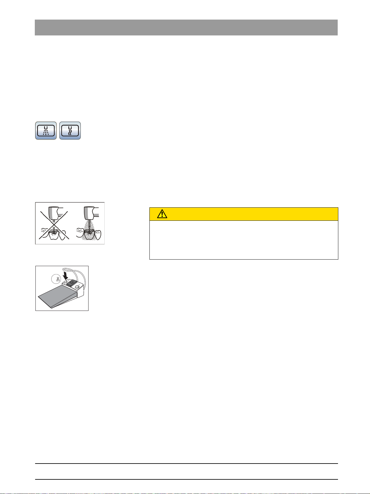
Sirona Dental Systems GmbH 4Operation
S
0
S
Operating Instructions Simulation Unit SIM MODULAR 4.5Dentist element
4.5.6.2.3 Preset and switch coolant on/off by the C+ electronic foot switch.
Selecting a coolant
Air or spray can be preselected as the instrument coolant in the subdialog. The preselected coolant can be switched on/off via the left button
on the C+ electronic foot switch.
✔ The
sub-dialog
of the removed instrument is displayed on the
touchscreen.
➢ Select the coolant required for the instrument removed from the
holder. Touch the
(left) or
Air
(right) key.
Spray
The key of the preselected coolant is highlighted orange in the
sub-dialog. In the instrument dialog, the preselected coolant is
indicated in the status column with a spray or air symbol.
Switching the coolant on/off
The preselected coolant is switched on when the foot pedal is pressed
while the instrument is activated. The spray can be switched on/off via the
foot switch.
Cooling of treatment areas
CAUTION
Instrument can be operated without coolant.
Tooth substance can be damaged by frictional heat.
➢ Always make sure that the treatment area does not overheat
whenever you switch the coolant off.
✔ An instrument is removed from the holder.
➢ Press the left button of the C+ electronic foot switch.
If the preselected coolant is switched on, it will be displayed in the
status column of the start and instrument dialog with a spray or
air symbol. When the instrument is activated, the preselected
medium will be switched on.
bеЦдблЬ
65 64 020 D3650
D3650.201.01.02.02 04.2016
Activation of the spray is saved on the favorite keys, see section "Setting
the speed on the EasyTouch" [ → 75], "Setting the intensity on the
EasyTouch" [ → 93] and "Integrated torque control on the EasyTouch"
[ → 85].
63
Page 64

4Operation Sirona Dental Systems GmbH
S
0
0
Auto
Rev
Apex
Stop
Apex Dist
Apex Dist
4.5Dentist element Operating Instructions Simulation Unit SIM MODULAR
4.5.6.2.4 Activating the chip blower
With the chip blower, an air jet comes out of the burr instrument nozzle.
✔ A highspeed handpiece or motor is removed from the holder.
➢ Press the right button of the pneumatic or C+ electronic foot switch.
The chip blower remains switched on as long as the button is
pressed.
4.5.6.2.5 Setting the ApexLocator
If your simulation unit is equipped with the ApexLocator option, you can
Motor
configure this in the first and second
information, refer to the chapter "ApexLocator", section "Endodontic
treatments with ApexLocator and torque limitation handpiece".
sub-dialog. For more
The ApexLocator is available only with the EasyTouch comfort user
interface.
4.5.6.2.6 Setting the C+ electronic foot switch as a direct starter or speed
control foot switch
To operate the motor or scaler SIROSONIC L the C+ electronic foot
switch can be set as a direct starter or a control foot switch:
● Direct starter
When the foot switch is actuated, the instrument is switched on with
the set speed and intensity.
● Control foot switch
Depending on the setting of the foot switch, the instrument controls
the speed and intensity continuously up to the maximum value set.
✔ The
sub-dialog
of the removed instrument is displayed on the
touchscreen.
1. Only in the
Motor
sub-dialog: Press the fixed
Sub-dialog
key again.
The second sub-dialog is displayed.
65 64 020 D3650
64 D3650.201.01.02.02 04.2016
Page 65

Sirona Dental Systems GmbH 4Operation
rpm
28000
1.2 4028
Set
1
2
Setup
3
Operating Instructions Simulation Unit SIM MODULAR 4.5Dentist element
2. Touch the
If the key is highlighted gray, the direct starter function is switched
4.5.6.3
DropMode When placing an instrument back in the holder, the instrument settings
Favorite keys
4.5.6.4
Saving instrument settings
made are always saved in the user profile (DropMode).
The next time the instrument is removed, the last settings made are
available again.
The instrument settings speed or intensity, maximum torque if torque
control is activated, and activating spray (only with C+ electronic foot
switch) can be saved on one of the three favorite keys. The instrument
settings can be called up again by pressing the key or actuating the C+
foot switch, see section "Setting the speed" [ → 73], "Setting the intensity"
[ → 90] and "Integrated torque control" [ → 79].
Setting the amount of spray water
The amount of spray air or water is factory preset for the instruments. This
basic setting and the compressed air for the turbines can be changed by
the service technician.
Direct starter/control foot switch
on. If the key is highlighted orange, the speed control foot switch
function is switched on.
key.
bеЦдблЬ
The amount of spray water can be adjusted for each individual instrument
by the user. The amount of air remains constant. To do this, rotating water
controls are located under the instrument holder of the dentist element.
If the control for an instrument is completely closed, the treatment site is
cooled only with air.
1. Rotate the water knob on the respective instrument.
Reduce water quantity in spray: Turn knob clockwise to close
Increase water quantity if spray: Turn knob counterclockwise to open
2. Test the setting for spray water. Correct the setting if necessary.
65 64 020 D3650
D3650.201.01.02.02 04.2016
65
Page 66

4Operation Sirona Dental Systems GmbH
A
B
4.5Dentist element Operating Instructions Simulation Unit SIM MODULAR
4.5.7 3-way standard and SPRAYVIT E syringe
The 3-way syringe is used to clean the treatment areas and blow them
dry. It supplies air and water media.
IMPORTANT
Also note the SPRAYVIT operating instructions as well as the
information on care of the 3-way syringe Standard in the section
Cleaning and sterilizing the standard 3-way syringe [ → 169].
4.5.7.1
4.5.7.2
Safety instructions
Multifunctional syringe, a ir jet falling out
WARNING
The nozzle of the Standard 3-way syringe must lock into the holder.
Otherwise, the jet could fall out during treatment.
➢ Prior to treatment, ensure that the jet is securely in place.
Multifunctional syringe, water and air leakage
CAUTION
Leakage of air or water leak when the instrument or hose is replaced
If the Standard or SPRAYVIT E 3-way syringe is removed from the
instrument hose while the simulation unit is in use, water and air will
escape from the hose coupling. When the instrument hose is unscrewed
from the simulation unit, water and air also leaks out under the dentist
or assistant element.
➢ You should therefore switch off the simulation unit before changing
an instrument or hose.
➢ Release any remaining air and water pressure by actuating a 3-way
syringe Standard or SPRAYVIT E before changing the hose or the
instrument.
Using the standard 3-way syringe
➢ Press the
Air flows out of the instrument tip.
➢ Press the
Water flows out of the instrument tip.
➢ Press the
Spray flows out of the instrument tip.
For more information on lubrication, see the Cleaning and sterilizing the
standard 3-way syringe" [ → 169] section.
Air
key (A).
Water
key (B).
Air
key A and the
Water
key B simultaneously.
66 D3650.201.01.02.02 04.2016
65 64 020 D3650
Page 67

Sirona Dental Systems GmbH 4Operation
B
A
Operating Instructions Simulation Unit SIM MODULAR 4.5Dentist element
4.5.7.3
Using the 3-way SPRAYVIT E syringe
The following instructions apply to the standard version (water on the
right) of the SPRAYVIT E 3-way syringe. A SPRAYVIT E with inverted
media (water on the left) is available as an option.
Air
➢ Press the
Air flows out of the instrument tip.
➢ Press the
Water flows out of the instrument tip.
➢ Press the
Spray flows out of the instrument tip.
For more information on operation and care, please refer to the operating
instructions of the SPRAYVIT.
key (A).
Water
key (B).
Air
key A and the
Water
key B simultaneously.
bеЦдблЬ
65 64 020 D3650
D3650.201.01.02.02 04.2016
67
Page 68

4Operation Sirona Dental Systems GmbH
A
10:45:03
2
1
0S
4.5Dentist element Operating Instructions Simulation Unit SIM MODULAR
4.5.8 Turbine / air motor / other air-driven instruments
IMPORTANT
Please see the operating instructions for the various turbines, air
motors, or air-driven instruments.
The turbine hose has a standardized coupling as per ISO 9168.
Operation of a highspee d handpiece with the pneum atic foot switch
If your simulation unit is equipped with the pneumatic foot control, the
drive air for the turbine can be regulated by the foot pedal.
If instruments with a high air flow rate (e.g., SIROBoost from Sirona) are
operated with the pneumatic foot switch, the operating pressure is
reduced from 2.9 bar to 2.7 bar.
4.5.8.1
4.5.8.2
Using the highspeed handpiece
EasyPad user interface
When the highspeed handpiece is removed from the holder, a short
vertical bar appears on the right side of the EasyPad display. Press the
foot switch to start the instrument.
EasyTouch user interface
When the highspeed handpiece is removed from the holder, a highspeed
handpiece signal appears on the touchscreen.
Setting the light of the highspeed handpiece
Instrument light optional with INTE GO
The instrument light supply is optional in SIM MODULAR.
Halogen lamps cannot be operated with the SIM MODULAR simulation
unit.
The voltage or current can be limited for the LED lamp of the highspeed
handpiece. The power supply for the instrument light can also be
switched off.
The original Sirona halogen and LED lamps are usually operated at 3.6
V. For lamps made by other manufacturers, the settings may have to be
adjusted.
Lamps, restriction of voltage or current
NOTICE
The operating voltages and operating currents of different lamps may
vary.
Overvoltages or excess current can lead to damage.
➢ When changing lamps, make sure that the operating voltage or
operating current is properly set for the new lamp.
65 64 020 D3650
68 D3650.201.01.02.02 04.2016
Page 69

Sirona Dental Systems GmbH 4Operation
2
Setup
2
Setup
1
2
Setup
3
2
Setup
3
2
Setup
Operating Instructions Simulation Unit SIM MODULAR 4.5Dentist element
4.5.8.2.1 Setting the highspeed handpiece lamp on the EasyPad
Accessing the turbine light operating context
1. Detach the turbine to be set from the holder.
2. Press and hold the function key
2 / Setup
(> 2 s).
The
Instrument light
EasyPad screen. The selection focus
operating context is displayed on the
Voltage
(U) flashes.
Limiting voltage
✔ The selection focus
1. Press the function key
The setting focus
2. Set the voltage for the lamp of the turbine selected in volts using
favorite keys 1 and 3.
3. Confirm the setting by pressing the function key
The voltage is limited to the level set. The operating context
Turbine
appears.
Voltage
(U) flashes.
2 / Setup
.
Setting the voltage
flashes.
2 / Setup
.
bеЦдблЬ
65 64 020 D3650
D3650.201.01.02.02 04.2016
Limiting current
✔ The selection focus
1. Press favorite key 3.
The selection focus flashes
2. Press the function key
The setting focus
Voltage
Setting the current strength
(U) flashes.
2 / Setup
Current strength
.
(A) flashes.
flashes.
69
Page 70
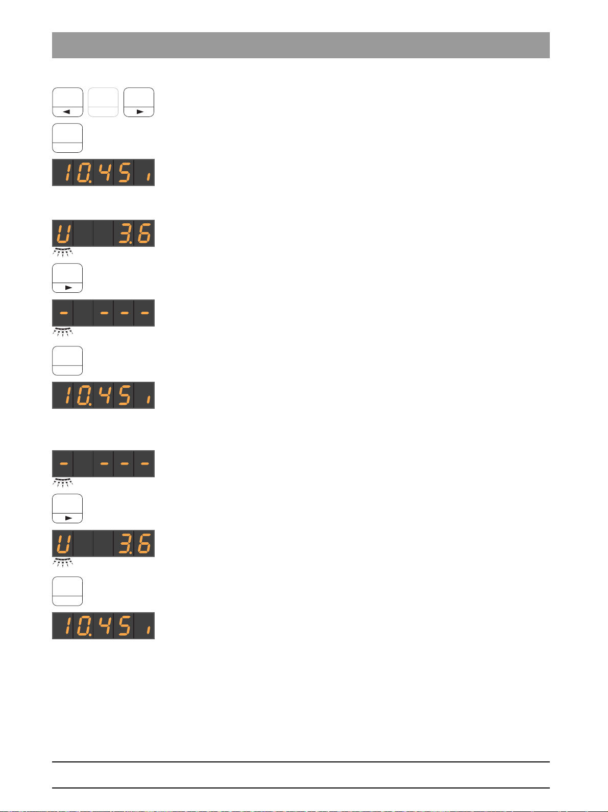
4Operation Sirona Dental Systems GmbH
1
2
Setup
3
2
Setup
3
2
Setup
3
2
Setup
4.5Dentist element Operating Instructions Simulation Unit SIM MODULAR
3. Use favorite keys 1 and 3 to set the current (A) for the lamp in the
handpiece removed in amperes (0.12 A = 120 mA).
4. Confirm the setting by pressing the function key
The current is limited to the level set. The operating context
Turbine
appears.
2 / Setup
Switching instrument light off
✔ The selection focus
1. Press the favorite key 3 twice.
The selection focus
2. Confirm your choice by pressing the function key
The power supply for the removed highspeed handpiece is
switched off. The operating context
appears.
Voltage
Light off
(U) flashes.
(–) flashes.
2 / Setup
Highspeed handpiece
.
.
Switching instrument light on
✔ The selection focus
1. Press the favorite key 3 twice.
The selection focus
2. Confirm your choice by pressing the function key
The power supply for the removed highspeed handpiece is
switched on. The operating context
appears.
Light off
Voltage
(–) flashes.
(U) flashes.
2 / Setup
Highspeed handpiece
.
70 D3650.201.01.02.02 04.2016
65 64 020 D3650
Page 71

Sirona Dental Systems GmbH 4Operation
---
mA
V
3.20 V
---
mA
V
120 mA
Operating Instructions Simulation Unit SIM MODULAR 4.5Dentist element
4.5.8.2.2 Setting the highspeed handpiece light on the EasyTouch
1. Detach the turbine to be set from the holder.
2. Press the
Sub-dialog
fixed key.
The
3. Touch the
The instrument setup
4. To set the voltage for the lamp of the highspeed handpiece which has
been removed, touch the key
highlighted orange.Use the – and + keys to set the voltage in volts.
Use the – and + keys to set the voltage in volts.
5. Touch the
The
6. Use the – and + keys to set the current for the lamp of the highspeed
handpiece removed from the holder in milliampere.
Highspeed handpiece
touchscreen.
Instrument Setup
touchscreen.
V / mA / ---
Milliampere (mA)
sub-dialog is displayed on the
key.
Highspeed handpiece
V / mA / ---
key.
field is highlighted orange.
, until the field
appears on the
V (Volt)
is
bеЦдблЬ
65 64 020 D3650
D3650.201.01.02.02 04.2016
---
If the
handpiece removed from the holder is switched off.
field is highlighted the power supply for the instrument light of the
71
Page 72

4Operation Sirona Dental Systems GmbH
4.5Dentist element Operating Instructions Simulation Unit SIM MODULAR
4.5.9 Electric motor
Electric motor, observe the operating Instructions
IMPORTANT
Also observe the operating instructions for the motor.
4.5.9.1
BL ISO E motor
The brushless BL ISO E motor is available as an electric motor.
Brushless motors are designed as three-phase motors (without carbon
brushes). They are characterized by their precise controllability and
durability.
The green coded instrument hose (GN) must be used for the BL ISO E
motors.
The BL ISO E motor is equipped with an ISO coupling. T1 LINE and
handpieces can thus be used without an adapter.
With SIM MODULAR the speed range of the BL ISO E motor is 1,200 to
40,000 rpm.
The motor can be used for integrated torque control.
The motor can be sterilized.
Reference to apex measurement via the instrument
For information on performing apex measurement using the instrument,
refer to the section “Preparing to use the ApexLocator”.
WARNING
The magnetic field of the electric motor is strengthened when the motor
is switched on.
This magnetic field can affect any cardiac pacemaker located nearby.
72 D3650.201.01.02.02 04.2016
65 64 020 D3650
Page 73

Sirona Dental Systems GmbH 4Operation
1
2
Setup
3
S
0
1
2
Setup
3
S
0
Operating Instructions Simulation Unit SIM MODULAR 4.5Dentist element
4.5.9.2
Setting the speed on the EasyPad
Speeds are stored on the favorite keys 1, 2, and 3 that can be accessed
by pressing them. Individual speeds can be saved for each user profile on
the favorite keys.
On the C+ electronic foot switch, spray activation is saved on the favorite
keys. The settings can also be made via the 4-way switch plate.
Accessing saved speed
✔ The electric motor is removed from the holder.
✔ The set speed is shown on the EasyPad display.
➢ Press one of the favorite keys briefly (<1 s).
The speed saved on the favorite key is shown in rpm (revolutions
per minute) on the EasyPad display.
By moving the 4-way switch plate of the C+ electronic foot switch to the
right, the settings of the favorite keys can be accessed consecutively.
bеЦдблЬ
Changing the speed
➢ Press and hold the favorite key 1 or 3 (> 1 s).
The speed is increased or reduced.
The speed can also be increased or reduced by moving the 4-way switch
plate of the C+ electronic foot switch up or down.
Electric motor, increments with favorite keys
IMPORTANT
Increments
The size of the increments depends on the speed range setting.
From 100 to 1,000 rpm = 100 rpm increments (with eControl option)
From 1,000 to 2,000 rpm = 200 rpm increments
From 2,000 to 5,000 rpm = 500 rpm increments
From 5,000 to 10,000 rpm = 1,000 rpm increments
From 10,000 to 20,000 rpm = 2,000 rpm increments
From 20,000 to 40,000 rpm = 5,000 rpm increments
Please note that the speed of the burr depends on the selected straight
or contra-angle handpiece.
65 64 020 D3650
D3650.201.01.02.02 04.2016
73
Page 74

4Operation Sirona Dental Systems GmbH
2
Setup
1
2
Setup
3
A/B
4.5Dentist element Operating Instructions Simulation Unit SIM MODULAR
Saving the speed
✔ The desired speed is set.
✔ Via the C+ electronic foot switch: The spray is switched on or off (will
be saved).
1. Press and hold the favorite key
The speed flashes on the EasyPad display.
2. Press the favorite key 1, 2, or 3.
An acoustic signal sounds. The set speed and if applicable,
activation of spray is saved on the favorite key.
While the speed flashes and is displayed on the EasyPad display,
pressing the
saving to a favorite key.
Counterclockwise rotation/user profile
2 / Setup
(> 2 s).
key will interrupt
74 D3650.201.01.02.02 04.2016
65 64 020 D3650
Page 75

Sirona Dental Systems GmbH 4Operation
B
10:45:03
2
1
0S
rpm
20000
1.2 4020
Set
S
0
rpm
28000
1.2 4020
Set
S
0
Operating Instructions Simulation Unit SIM MODULAR 4.5Dentist element
4.5.9.3
Setting the speed on the EasyTouch
Speeds are saved on the three favorite keys that can be accessed by
pressing them. Individual speeds can be saved for each user profile on
the favorite keys.
On the C+ electronic foot switch, spray activation is saved on the favorite
keys. The settings can also be made via the 4-way switch plate.
Accessing saved speed
✔ The electric motor is removed from the holder.
✔ The
➢ Touch one of the favorite keys in the bottom line briefly (< 1 s).
Electric motor, speeds on the favorite k eys
Motor dialog
is displayed on the touchscreen.
The favorite key is highlighted orange. At the left of the favorite
key, the selected speed is displayed in rpm (revolutions per
minute).
IMPORTANT
Speeds on the favorite keys
The speed of the motor in rpm equals 1,000 times the speed shown on
the key. Example:
Key value 0.1 = 100 rpm (with eControl option)
Key value 1.2 = 1,200 rpm
Key value 20 = 20,000 rpm
Key value 40 = 40,000 rpm
bеЦдблЬ
Please note that the speed of the burr depends on the selected straight
or contra-angle handpiece.
By moving the 4-way switch plate of the C+ electronic foot switch to the
right, the settings of the favorite keys can be accessed consecutively.
Changing the speed
➢ Press and hold the left or right favorite key (> 1 s).
The speed is increased or reduced. The favorite keys are shaded
gray for intermediate values.
The speed can also be increased or reduced by moving the 4-way switch
plate of the C+ electronic foot switch up or down.
65 64 020 D3650
D3650.201.01.02.02 04.2016
75
Page 76
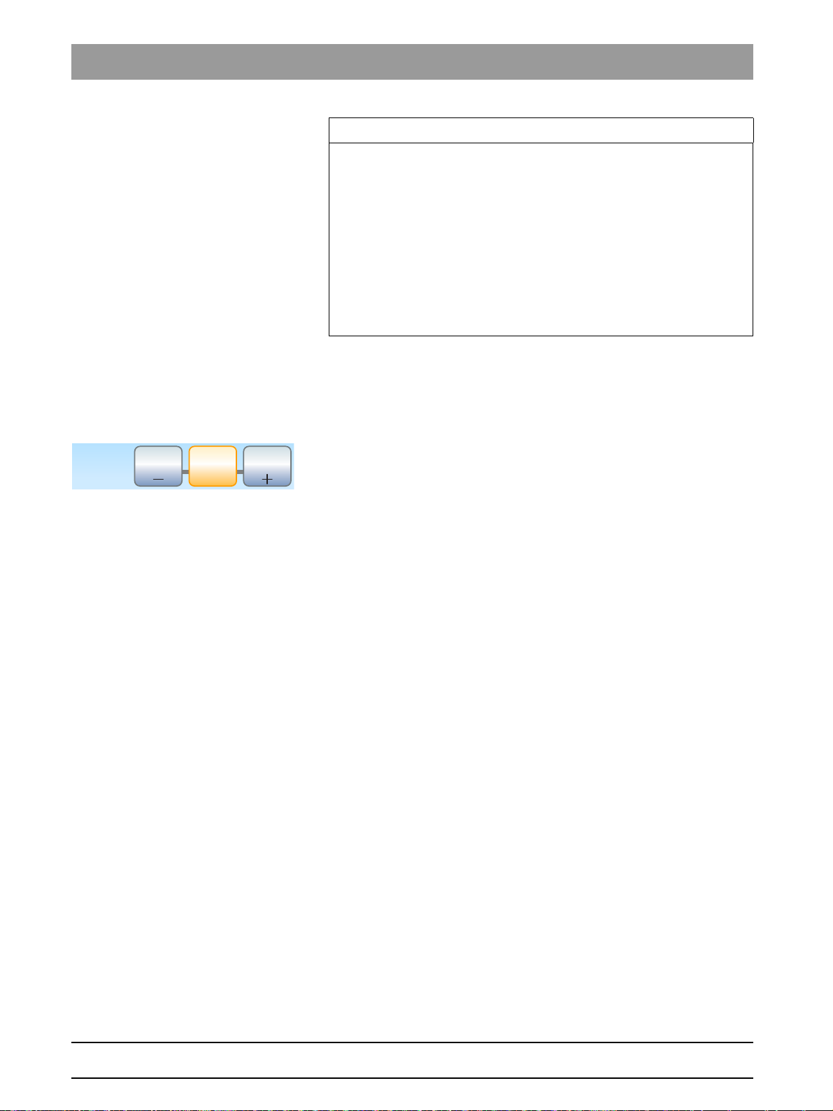
4Operation Sirona Dental Systems GmbH
rpm
28000
1.2 4028
Set
4.5Dentist element Operating Instructions Simulation Unit SIM MODULAR
Electric motor, increments with favorite keys
IMPORTANT
Increments
The size of the increments depends on the speed range setting.
From 100 to 1,000 rpm = 100 rpm increments (with eControl option)
From 1,000 to 2,000 rpm = 200 rpm increments
From 2,000 to 5,000 rpm = 500 rpm increments
From 5,000 to 10,000 rpm = 1,000 rpm increments
From 10,000 to 20,000 rpm = 2,000 rpm increments
From 20,000 to 40,000 rpm = 5,000 rpm increments
Please note that the speed of the burr depends on the selected straight
or contra-angle handpiece.
Saving the speed
✔ The desired speed is set.
✔ Via the C+ electronic foot switch: The spray is switched on or off (will
be saved).
Set
1. Press and hold the middle favorite
The speed flashes on the touchscreen.
(> 2 s).
2. Press one of the three favorite keys.
An acoustic signal sounds. The set speed and if applicable,
activation of spray is saved on the favorite key. The speed set is
displayed on the favorite key.
While the speed flashes and is displayed on the touchscreen, pressing
any other key on the touchscreen will interrupt saving to a favorite key.
76 D3650.201.01.02.02 04.2016
65 64 020 D3650
Page 77

Sirona Dental Systems GmbH 4Operation
A/B
B
S
0
Operating Instructions Simulation Unit SIM MODULAR 4.5Dentist element
4.5.9.4
Setting the direction of rotation
The direction of rotation can be changed only when the motor is at a
standstill.
Tip: After starting the electric motor with the foot switch, an audible
warning signal sounds 6 times if counterclockwise rotation is activated.
Via EasyPad
✔ An electric motor is removed from the holder.
➢ Press the
The
Counterclockwise rotation / User profile
Counterclockwise rotation
counterclockwise rotation is set.
Via the touchscreen of the EasyTouch
status display lights up when
key.
✔ An electric motor is removed from the holder.
✔ The
➢ Touch the
Motor dialog
For counterclockwise rotation: The key is highlighted orange.
For clockwise rotation: The key is displayed in gray.
is displayed on the touchscreen.
Counterclockwise rotation
key on the touchscreen.
bеЦдблЬ
Via C+ electronic foot switch
The rotational direction of the motor can also be set via the 4-way foot
control plate of the C+ electronic foot switch.
✔ An electric motor is removed from the holder.
1. Move the 4-way foot control plate to the left.
When counterclockwise rotation is switched on, the
Counterclockwise
Counterclockwise
2. Move the 4-way foot control plate to the left again to reverse the
rotational direction.
status display lights up on the EasyPad, the
key is marked orange on the EasyTouch.
65 64 020 D3650
D3650.201.01.02.02 04.2016
77
Page 78
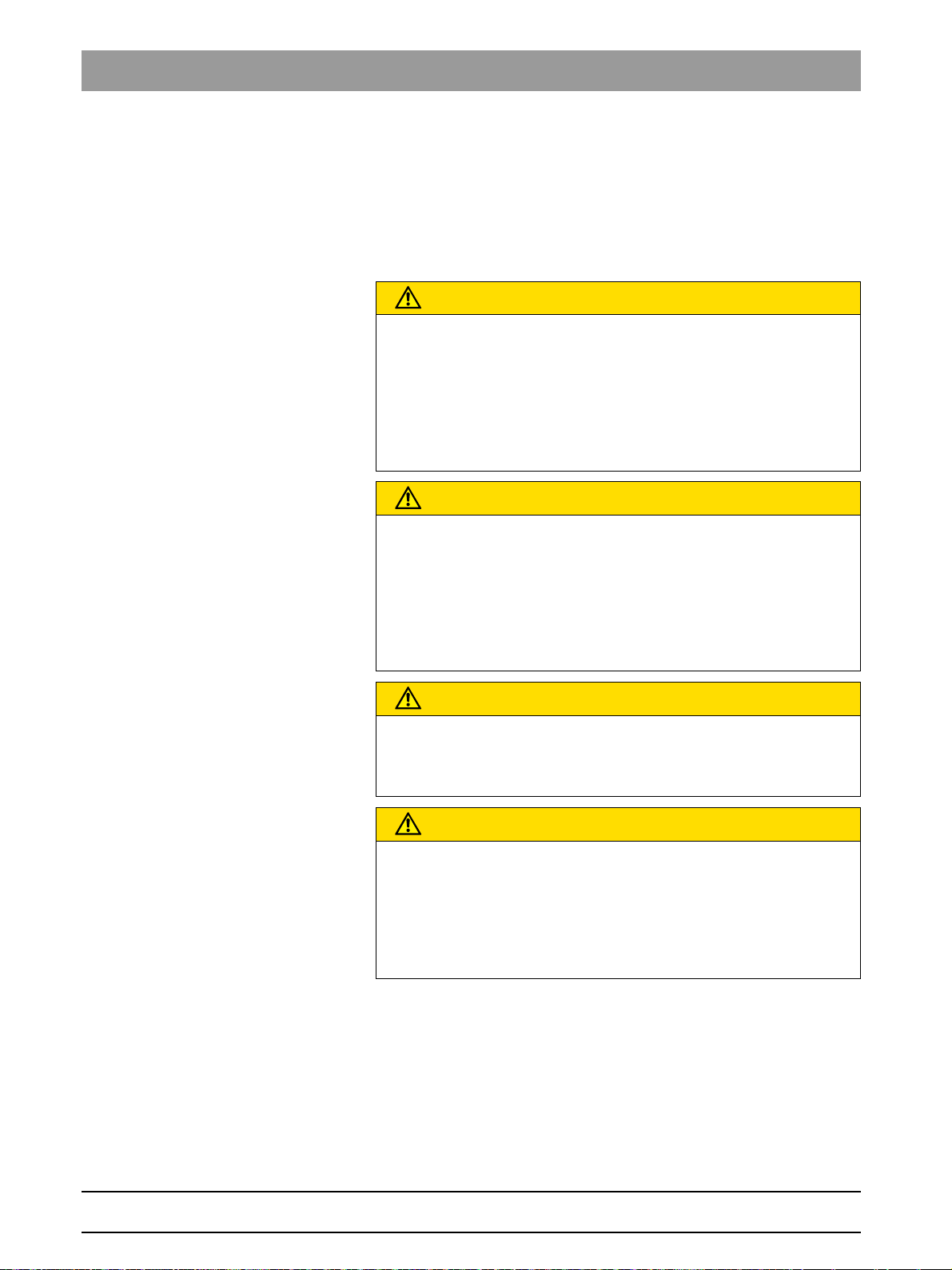
4Operation Sirona Dental Systems GmbH
4.5Dentist element Operating Instructions Simulation Unit SIM MODULAR
4.5.10 Integrated torque control
Speed and torque of the rotating instrument can be set precisely using the
integrated torque control.
With the integrated torque control on the EasyPad standard user
interface, speed and torque can be saved for up to three steps; on the
EasyTouch comfort user interface for up to six steps.
Endodontics without electron ic torque limitation
CAUTION
If your simulation unit is not equipped with the integrated torque control,
no electronic torque limitation is available.
Root canal files can easily break during operation without torque
limitation.
➢ Never perform endodontic treatments without torque limitation. Use
an endodontic handpiece with mechanical torque limitation, e.g.
SIRONiTi from Sirona.
Endodontics, root cana l file limiting values
CAUTION
Torque limitation does not always protect against file breakage!
The integrated torque control maintains the torque values which you
have set with a tolerance safety margin.
Please note: The limiting values stated by the file manufacturers are, as
standard, defined by means of uniform friction over the entire defined
working length. As a rule, this is physically not the practice-relevant
therapy situation.
Endodontics, material fatigue of files
CAUTION
Root canal files are subject to material fatigue
Fatigued files may break during treatment.
➢ Use files only for the service life specified by the manufacturer.
Contra-angle handpiece, integrated torque control
CAUTION
Only the Sirona ENDO 6:1 contra-angle handpiece may be used for
integrated torque control.
Instruments from other manufacturers can lead to malfunctions. Thirdparty instruments may be improperly calibrated for endodontics.
➢ Use the Sirona ENDO 6:1 contra-angle handpiece for integrated
torque control.
78 D3650.201.01.02.02 04.2016
65 64 020 D3650
Page 79

Sirona Dental Systems GmbH 4Operation
Purge
B
Purge
Operating Instructions Simulation Unit SIM MODULAR 4.5Dentist element
4.5.10.1
Integrated torque control on the EasyPad
4.5.10.1.1 Switching integrated torque control on/off
Switching torque control on
Torque control is assigned to the burr drive removed from the holder.
✔ The desired electric motor for torque control is removed from the
holder.
✔ The motor speed is shown on the EasyPad display.
➢ Press the
If the integrated torque control is switched on, the status display
The preset torque of 1.00 Ncm (Newton centimeters) is displayed
Endodontics / Purge
torque control
on the EasyPad display.
lights up.
Switching torque control off
If the integrated torque control is switched on, when the burr drive
assigned to the torque control is removed from the holder, the torque or
speed of the contra-angle handpiece is displayed instead of that of the
motor on the EasyPad display. To show the motor speed again when the
burr drive is removed, the integrated torque control must first be switched
off.
key.
bеЦдблЬ
➢ Press the
The
is removed from the holder, the speed of the motor is shown on
the EasyPad display.
Endodontics / Purge
torque control
status display goes out. When the burr drive
key briefly (< 1 s).
65 64 020 D3650
D3650.201.01.02.02 04.2016
79
Page 80

4Operation Sirona Dental Systems GmbH
/
S
0
0
Purge
/
S
0
/
4.5Dentist element Operating Instructions Simulation Unit SIM MODULAR
4.5.10.1.2 Calibrating the burr drive
Calibration is required when the integrated torque control is started, every
time the contra-angle handpiece is changed, and every time the contraangle handpiece is lubricated. Recalibration is not necessary when a file
is changed.
An uncalibrated burr instrument is marked with an "n" on the EasyPad
display. The horizontal bar above it shows that the AutoReverse function
is switched on, see "Switching AutoReverse ON/OFF" [ → 84]. If the autoreverse function is switched on, the burr drive automatically switches to
counterclockwise rotation when the torque set is reached.
The contra-angle handpiece is automatically checked during calibration.
This includes a measurement of motor current at different speeds to
assess the properties of the system.
Calibration only with Sirona ins tru ments
CAUTION
Use only Sirona instruments to guarantee correct calibration.
✔ Integrated torque control is switched on. The status display
control
lights up.
torque
✔ The torque is shown on the EasyPad display.
1. Attach the contra-angle handpiece that you wish to use with torque
control to the electric motor.
2. Insert a file in the contra-angle handpiece. This ensures that the file
is taken into account in the measurement.
3. Press and hold the
button of the C+ electronic foot control.
A revolving element is shown on the EasyPad display. The burr
drive is ready for calibration.
4. Hold down the foot pedal throughout the duration of the calibration.
The revolving element is still displayed. During calibration,
increasing speeds are set on the motor.
Endodontics / Purge
key (> 2 s) or press the right
When the burr drive is calibrated, a "c" is displayed on the
EasyPad display. Calibration is then completed.
65 64 020 D3650
80 D3650.201.01.02.02 04.2016
Page 81

Sirona Dental Systems GmbH 4Operation
1
2
Setup
3
S
0
Operating Instructions Simulation Unit SIM MODULAR 4.5Dentist element
4.5.10.1.3 Setting the torque
With the torque control switched on, torque and speed of the contra-angle
handpiece are indicated, but not of the motor. The control electronics of
the burr drive calculate the motor control based on the specified contrahandpiece gear reduction and the set torque and speed.
Torque values for the steps of the endodontic treatment can be stored on
the favorite keys 1, 2 and 3. The set speed remains unchanged.
Instrument settings can be made without using your hands on the 4-way
switch plate of the C+ electronic foot switch.
Endodontics, speed and torque set tings
Endodontics, speed and torque set tings
CAUTION
Damages, e.g. breaking of a file, may result from incorrect settings.
➢ Observe the manufacturer's instructions regarding file systems.
Treatment, torque adjustme nt
IMPORTANT
Torque adjustment
The maximum adjustable torque depends on the system motor and the
speed settings.
Accessing saved torque
bеЦдблЬ
✔ The electric motor is removed from its holder with torque control
switched on.
✔ The set torque is shown on the EasyPad display.
➢ Press one of the favorite keys briefly (<1 s).
The torque saved on the favorite key is shown on the EasyPad
display in Ncm (Newton centimeters).
By moving the 4-way switch plate of the C+ electronic foot switch to the
right, the torque settings of the favorite keys can be accessed
consecutively.
65 64 020 D3650
D3650.201.01.02.02 04.2016
81
Page 82

4Operation Sirona Dental Systems GmbH
1
2
Setup
3
S
0
2
Setup
1
2
Setup
3
A/B
4.5Dentist element Operating Instructions Simulation Unit SIM MODULAR
Changing torque
➢ Set the desired torque for the contra-angle handpiece. Press and
hold the favorite keys 1 or 3 (> 1 s).
The torque is increased or reduced.
The torque can also be increased or reduced by moving the 4-way switch
plate of the C+ electronic foot switch up or down.
Saving torque
✔ The desired torque is set.
1. Press and hold the favorite key
2 / Setup
(> 2 s).
The torque flashes on the EasyPad display.
2. Press the favorite key 1, 2, or 3.
An acoustic signal sounds. The torque setting is saved on the
favorite key.
While the torque flashes and is displayed on the EasyPad display,
pressing the
Counterclockwise rotation/user profile
key will interrupt
saving to a favorite key.
65 64 020 D3650
82 D3650.201.01.02.02 04.2016
Page 83

Sirona Dental Systems GmbH 4Operation
Ncm
rpm
Clean
1
2
Setup
3
S
0
S
0
Operating Instructions Simulation Unit SIM MODULAR 4.5Dentist element
4.5.10.1.4 Setting the speed
When the torque control is switched on, the EasyPad display can be
toggled between torque and speed to set the speed.
To differentiate between torque and speed settings, the display shows
burr drive calibrated/not calibrated and AutoReverse function on/off only
for the torque.
Speed is not saved on the favorite keys, only torque.
✔ The torque is shown on the EasyPad display.
1. Press the
Display mode / Clean
The selected speed is shown on the EasyPad display in rpm
(revolutions per minute).
2. Set the desired speed for the contra-angle handpiece. Press and hold
the favorite keys 1 or 3 (> 1 s).
The speed is increased or reduced.
key.
The speed can also be increased or reduced by moving the 4-way switch
plate of the C+ electronic foot switch up or down.
Moving the 4-way switch plate of the C+ electronic foot switch to the left
also toggles between torque and speed.
bеЦдблЬ
65 64 020 D3650
D3650.201.01.02.02 04.2016
83
Page 84

4Operation Sirona Dental Systems GmbH
A/B
/
A/B
B
4.5Dentist element Operating Instructions Simulation Unit SIM MODULAR
4.5.10.1.5 Switching AutoReverse ON/OFF
If the auto-reverse function is switched on, the burr drive automatically
switches to counterclockwise rotation when the torque set is reached. If
the foot pedal is pressed again, the burr drive switches back to clockwise
rotation.
✔ The electric motor is removed from its holder with torque control
switched on.
➢ Press and hold the
(> 2 s).
The AutoReverse function is switched on/off. On the EasyPad
display, a horizontal bar appears above the
Burr drive not calibrated
or
4.5.10.1.6 Changing direction of rotation
The direction of rotation can be changed only with the motor stopped.
Counterclockwise rotation is performed without torque limitation.
Counterclockwise rotation / User profile
Burr drive calibrated
display.
key
Tip: After starting the electric motor with the foot switch, an audible
warning signal sounds 6 times if counterclockwise rotation is activated.
✔ The electric motor is removed from its holder with torque control
switched on.
➢ Press the
The
When torque control is switched on, counterclockwise rotation cannot be
activated via the C+ electronic foot switch.
Counterclockwise rotation/user profile
Counterclockwise rotation
counterclockwise rotation is set.
status display lights up when
key briefly (< 2 s).
84 D3650.201.01.02.02 04.2016
65 64 020 D3650
Page 85

Sirona Dental Systems GmbH 4Operation
B
10:45:03
2
1
0S
rpm
20000
1.2 4020
Set
Auto
Rev
Apex
Stop
2
1
0S
rpm
300
Ncm
1.00
Endo 3
Cal
Operating Instructions Simulation Unit SIM MODULAR 4.5Dentist element
4.5.10.2
Integrated torque control on the EasyTouch
Switching integrated torque control on/off
Switching torque control on
Torque control is assigned to the burr drive removed from the holder.
✔ The desired electric motor for torque control is removed from the
holder.
✔ The motor speed and favorite keys are shown.
1. Press the
The
Sub-dialog
Motor
fixed key.
sub-dialog is displayed.
bеЦдблЬ
2. Press the
The
Integrated torque control
Endodontics dialog
is displayed on the touchscreen.
key.
65 64 020 D3650
D3650.201.01.02.02 04.2016
85
Page 86

4Operation Sirona Dental Systems GmbH
2
1
0S
rpm
300
Ncm
1.00
Endo 3
Cal
rpm
300
Ncm
1.00
Endo 3
Cal
4.5Dentist element Operating Instructions Simulation Unit SIM MODULAR
Switching torque control off
If the integrated torque control is switched on when the burr drive
assigned to the torque control is removed from the holder, the
Endodontics dialog
touchscreen. To show the motor speed again when the burr drive is
removed, the integrated torque control must first be switched off.
is displayed in place of the
Motor dialog
on the
✔ The electric motor assigned to the integrated torque control is
removed from the holder.
✔ The
Endodontics dialog
is displayed on the touchscreen.
1. Press the
The
2. Press the
If the key is blue, the integrated torque control is switched off.
Sub-dialog
Endodontics
Integrated torque control
When the burr drive is taken from the holder, the
called up.
fixed key.
sub-dialog is displayed.
key.
Motor screen
is
65 64 020 D3650
86 D3650.201.01.02.02 04.2016
Page 87

Sirona Dental Systems GmbH 4Operation
rpm
300
Ncm
1.00
Endo 3
Cal
2
1
0S
rpm
300
Ncm
1.00
Endo 3
Cal
Cal
S
0
0
S
0
Operating Instructions Simulation Unit SIM MODULAR 4.5Dentist element
Calibrating the burr drive
Calibration is required when the integrated torque control is started, every
time the contra-angle handpiece is changed, and every time the contraangle handpiece is lubricated. Recalibration is not necessary when a file
is changed.
The contra-angle handpiece is automatically checked during calibration.
This includes a measurement of motor current at different speeds to
assess the properties of the system.
Calibration only with Siro na instruments
CAUTION
Use only Sirona instruments to guarantee correct calibration.
✔ The
Endodontics dialog
or the
Endodontics
sub-dialog is displayed
on the touchscreen.
1. Attach the contra-angle handpiece that you wish to use with torque
control to the electric motor.
2. Insert a file in the contra-angle handpiece. This ensures that the file
is taken into account in the measurement.
Cal
3. Touch the
key on the touchscreen.
or
➢ Press the right button of the C+ electronic foot switch.
The key flashes. The burr drive is ready for calibration.
bеЦдблЬ
65 64 020 D3650
D3650.201.01.02.02 04.2016
4. Hold down the foot pedal throughout the duration of the calibration.
The
Cal
key continues to flash. During calibration, increasing
speeds are set on the motor. If the burr drive is calibrated, the key
permanently remains highlighted orange. Calibration is then
completed.
87
Page 88

4Operation Sirona Dental Systems GmbH
S
0
Endo 3
4.5Dentist element Operating Instructions Simulation Unit SIM MODULAR
4.5.10.2.1 Changing direction of rotation
The direction of rotation can be changed only with the motor stopped.
Counterclockwise rotation is performed without torque limitation. The
torque setting keys are hidden when counterclockwise rotation is
selected.
Tip: After starting the electric motor with the foot switch, an audible
warning signal sounds 6 times if counterclockwise rotation is activated.
✔ The
Endodontics dialog
on the touchscreen.
➢ Touch the
Counterclockwise rotation
or
➢ Press the left button of the foot switch.
For counterclockwise rotation: The key
rotation
is highlighted orange and an orange counterclockwise
rotation arrow appears.
For clockwise rotation: The key
displayed in gray and the orange counterclockwise arrow is
hidden.
4.5.10.2.2 Selecting a working step
Speed and torque can be saved for up to six working steps. At the end of
each working step, the required settings can be accessed immediately by
selecting the next step.
✔ The
Endodontics dialog
on the touchscreen.
➢ Select the required endodontics working step. Touch the
next working step
key.
The selected working step is displayed on the touchscreen. The
settings saved in the working step are preset.
or the
or the
Endodontics
sub-dialog is displayed
key on the touchscreen.
Counterclockwise
Counterclockwise rotation
Endodontics
sub-dialog is displayed
is
previous
or
4.5.10.2.3 Setting the speed and torque
With the torque control switched on, torque and speed of the contra-angle
handpiece are indicated, but not of the motor. The control electronics of
the burr drive calculate the motor control based on the specified contrahandpiece gear reduction and the set torque and speed.
Endodontics, speed and torque s ettings
CAUTION
Damages, e.g. breaking of a file, may result from incorrect settings.
➢ Observe the manufacturer's instructions regarding file systems.
65 64 020 D3650
88 D3650.201.01.02.02 04.2016
Page 89

Sirona Dental Systems GmbH 4Operation
rpm
300
Ncm
1.00
Operating Instructions Simulation Unit SIM MODULAR 4.5Dentist element
Treatment, torque adjustme nt
IMPORTANT
Torque adjustment
The maximum adjustable torque depends on the system motor and the
speed settings.
✔ The
Endodontics
sub-dialog is displayed on the touchscreen.
✔ The working step with which the speed and torque are to be changed
is selected.
➢ Use the – and + keys to set the speed and torque of the contra-angle
handpiece. You can also hold down the keys for this purpose.
The selected speed is displayed in the first line in rpm
(revolutions per minute); the second line indicates the speed in
Ncm (Newton centimeters).
bеЦдблЬ
65 64 020 D3650
D3650.201.01.02.02 04.2016
89
Page 90

4Operation Sirona Dental Systems GmbH
1
2
Setup
3
S
0
4.5Dentist element Operating Instructions Simulation Unit SIM MODULAR
4.5.11 SIROSONIC L scaler
The SIROSONIC L scaler is used for removing plaque and rinsing the root
canal for endodontic treatments.
Ultrasonic handpiece, o bserve the operating Inst ructions
IMPORTANT
See also the SIROSONIC L operating instructions.
4.5.11.1
4.5.11.2
Safety instructions
The torque wrench is used as a tool for screwing in instrument tips and,
at the same time, to protect against injury.
Ultrasonic handpiece, t orque wrench
CAUTION
Ultrasonic tips are sharply pointed.
There is a risk of injuring one's hand on the deposited scaler.
➢ Always attach the torque wrench to the scaler for protection as soon
as you deposit the handpiece.
Ultrasonic handpiece, only Siro na tips
CAUTION
In some cases, ultrasonic tips from other manufacturers do not
guarantee safe operation.
➢ Use only ultrasonic tips from Sirona.
Setting the intensity on the EasyPad
Intensities are saved on the favorite keys 1, 2, and 3, which can be
accessed by pressing them. Individual intensities can be saved on the
favorite keys for each user profile.
On the C+ electronic foot switch, spray activation is saved on the favorite
keys. The settings can also be made via the 4-way switch plate.
Accessing intensity settings
✔ The SIROSONIC L scaler is removed.
✔ The intensity setting is shown on the EasyPad display.
➢ Press the favorite keys briefly (< 1 s).
The intensity saved on the favorite key is shown as a percentage
on the EasyPad display.
By moving the 4-way switch plate of the C+ electronic foot switch to the
right, the settings of the favorite keys can be accessed consecutively.
65 64 020 D3650
90 D3650.201.01.02.02 04.2016
Page 91

Sirona Dental Systems GmbH 4Operation
1
2
Setup
3
S
0
2
Setup
1
2
Setup
3
A/B
Operating Instructions Simulation Unit SIM MODULAR 4.5Dentist element
Changing the intensity
➢ Press and hold the favorite key 1 or 3 (> 1 s).
The intensity is increased or reduced.
The intensity can also be increased or reduced by moving the 4-way
switch plate of the C+ electronic foot switch up or down.
Ultrasonic handpiece, inte nsity settings
IMPORTANT
Increments
The size of the increments depends on the intensity range setting.
From 1 to 5% = 1% increments
From 5 to 50% = 5% increments
From 50 to 100% = 10% increments
Saving intensity
✔ The desired intensity is set.
✔ Via the C+ electronic foot switch: The spray is switched on or off (will
be saved).
1. Press and hold the favorite key
2 / Setup
The intensity flashes on the EasyPad display.
2. Press the favorite key 1, 2, or 3.
An acoustic signal sounds. The intensity set and, if applicable,
activation of spray will be saved on the favorite key.
While the intensity flashes on the EasyPad display, pressing the
Counterclockwise rotation / User profile
favorite key.
(> 2 s).
key will interrupt saving to a
bеЦдблЬ
65 64 020 D3650
D3650.201.01.02.02 04.2016
91
Page 92

4Operation Sirona Dental Systems GmbH
Purge
1
2
Setup
3
4.5Dentist element Operating Instructions Simulation Unit SIM MODULAR
Switching endodontics mode on
The intensity of the endodontics function is limited for safety reasons,
e.g., in order to prevent broken needles.
Ultrasonic handpiece, E ndo intensity values
IMPORTANT
Intensities in endodontics mode
The intensity can be set from 1e to 5e. Please note that the intensity
values of 1e to 5e (endodontics mode) do not correspond with the
values of 1 to 5 in the scaler mode (ultrasound mode).
Always use the endo mode for endodontics!
✔ The SIROSONIC L scaler is removed.
✔ The ultrasonic intensity setting (ultrasonic mode) is shown on the
EasyPad display.
1. Press the
Endodontics / Purge
The endodontics intensity (endo mode) is displayed instead of
ultrasonic intensity (ultrasonic mode).
key.
2. Use favorite keys 1 and 3 to set the desired endodontics intensity
(En 1 to En 5).
By pressing the
Endodontics / Purge
key again, the user is returned to
ultrasonic mode.
The intensity settings cannot be saved on the favorite keys in endo mode.
92 D3650.201.01.02.02 04.2016
65 64 020 D3650
Page 93
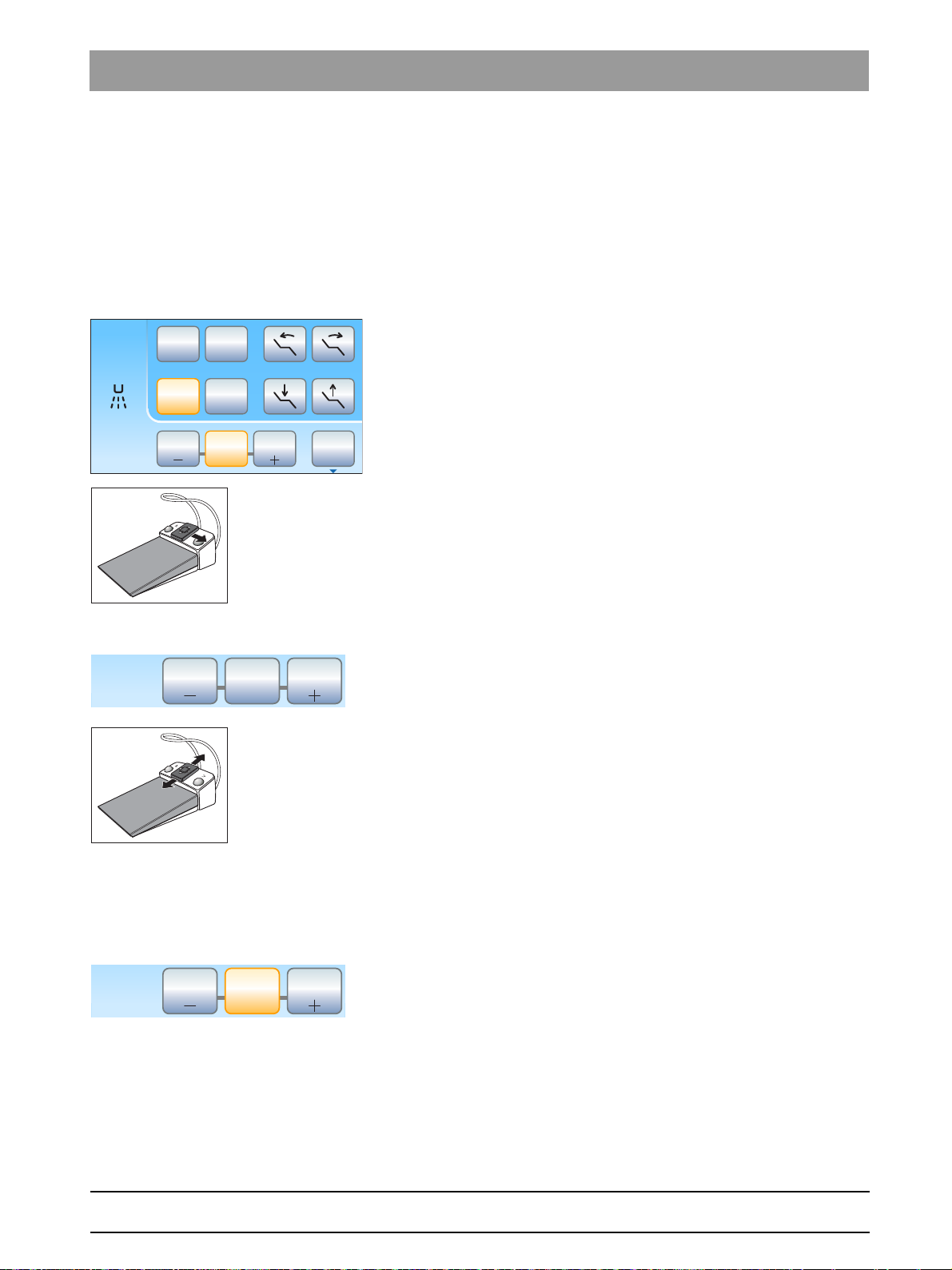
Sirona Dental Systems GmbH 4Operation
B
10:45:03
2
1
0S
50
Endo
1 10050
Set
S
0
20
1 10050
Set
S
0
20
1 10020
Set
Operating Instructions Simulation Unit SIM MODULAR 4.5Dentist element
4.5.11.3
Setting the intensity on the EasyTouch
Intensities are saved on the three favorite keys that can be accessed by
pressing them. Individual intensities can be saved on the favorite keys for
each user profile.
On the C+ electronic foot switch, spray activation is saved on the favorite
keys. The settings can also be made via the 4-way switch plate.
Accessing intensity settings
✔ The SIROSONIC L scaler is removed.
✔ The
➢ Touch one of the favorite keys in the bottom line briefly (< 1 s).
By moving the 4-way switch plate of the C+ electronic foot switch to the
right, the settings of the favorite keys can be accessed consecutively.
Ultrasonic dialog
The favorite key is highlighted orange. The selected intensity is
displayed to the left of the favorite keys.
is displayed on the touchscreen.
bеЦдблЬ
Changing the intensity
➢ Press and hold the left or right favorite key (> 1 s).
The intensity is increased or reduced. The favorite keys are
shaded gray for intermediate values.
The intensity can also be increased or reduced by moving the 4-way
switch plate of the C+ electronic foot switch up or down.
Saving intensity
✔ The desired intensity is set.
✔ Via the C+ electronic foot switch: The spray is switched on or off (will
be saved).
1. Press and hold the middle favorite
The intensity flashes on the touchscreen.
2. Press one of the three favorite keys.
An acoustic signal sounds. The intensity set and, if applicable,
activation of spray will be saved on the favorite key. The selected
intensity is displayed on the favorite key.
Set
(> 2 s).
65 64 020 D3650
D3650.201.01.02.02 04.2016
While the intensity flashes on the touchscreen, pressing any other key on
the touchscreen will interrupt saving to a favorite key.
93
Page 94

4Operation Sirona Dental Systems GmbH
B
10:45:03
2
1
0S
50
Endo
1 10050
Set
Endo
B
10:45:03
2
1
0S
3e
Endo
4.5Dentist element Operating Instructions Simulation Unit SIM MODULAR
Switching on the endodontics function
The intensity of the endodontics function is limited for safety reasons,
e.g., in order to prevent broken needles.
Ultrasonic handpiece, E ndo intensity values
IMPORTANT
Endo intensity values
The intensity can be adjusted from 1e to 5e. Please note that the
endodontics intensity values of 1e to 5e do not match the values of 1 to
5 in the calculus removal mode.
Always use the endo function for endodontics!
✔ The SIROSONIC L scaler is removed.
✔ The
Ultrasonic dialog
is displayed on the touchscreen.
➢ Touch the
The key is highlighted orange. In the ultrasonic dialog, the
Endo
key.
endodontics intensity is displayed instead of the ultrasonic
intensity.
65 64 020 D3650
94 D3650.201.01.02.02 04.2016
Page 95

Sirona Dental Systems GmbH 4Operation
SiroCamAF
Operating Instructions Simulation Unit SIM MODULAR 4.5Dentist element
4.5.12 Mini LED curing light
The function is described in the chapter on the assistant element, see
"Mini LED curing light" [ → 101].
4.5.13 SiroCam F/AF/AF+ intraoral camera
Functionality is described in the "SIVISION digital video system" section,
see "SiroCam F / AF / AF+ intraoral camera".
bеЦдблЬ
65 64 020 D3650
D3650.201.01.02.02 04.2016
95
Page 96
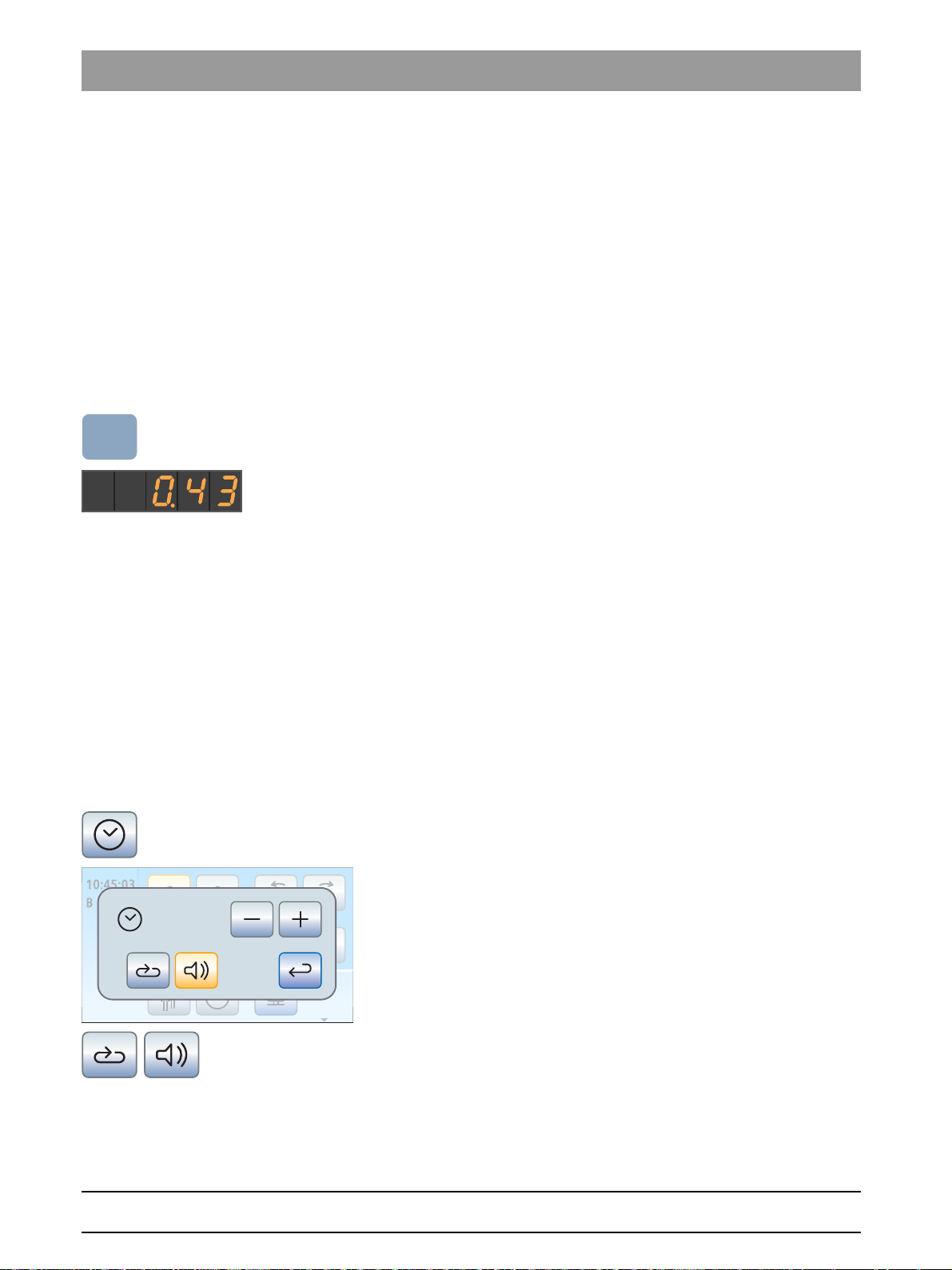
4Operation Sirona Dental Systems GmbH
Fn
B
10:45:03
2
1
0S
0:15
4.5Dentist element Operating Instructions Simulation Unit SIM MODULAR
4.5.14 Timer function
4.5.14.1
4.5.14.2
Timer function on the EasyPad
The Fn function key is assigned to the timer function.
Presetting the timer
A set time can be counted down to zero with the timer function.
The timer is preset in the
timer" [ → 137].
Setup
of the simulation unit, see "Presetting the
Starting, stopping/resetting the timer
✔ The time or speed/intensity is shown on the EasyPad display.
Fn
➢ Press the
The timer is started immediately. The preset time counts down on
the EasyPad display.
When the time is up, a short acoustic signal sounds.
Press again to stop the timer and reset the countdown. It can then be
restarted.
key.
Timer function on the EasyTouch
A set time can be counted down to zero with the timer function. A time
loop (automatic restart of the countdown) and an acoustic signal (when
the set time has expired) can be added to each timer.
Presetting the timer
The maximum time setting is 9 minutes and 30 seconds.
✔ The
1. Press and hold the
2. Use the
3. Select whether you want to switch the time loop (i.e. the timer resta r ts
Start dialog
instrument is shown on the touchscreen.
The
touchscreen.
–
Increments:
From 00:05 to 1:00 = 5 s steps
From 1:00 to 3:00 = 10 s steps
From 3:00 to 9:30 = 30 s steps
automatically after the time is up) and the acoustic signal for the
selected timer on or off. Touch the
key.
If a function is switched on, the corresponding key is highlighted
orange.
of the
Timer Function
and + keys to set the required time.
highspeed handpiece
Timer
key on the touchscreen (> 2 s).
setting dialog is displayed on the
Time loop
or the
and/or
sub-dialog
of an
Acoustic signal
65 64 020 D3650
96 D3650.201.01.02.02 04.2016
Page 97

Sirona Dental Systems GmbH 4Operation
B
10:45:03
2
1
0S
0:02 0:15
Operating Instructions Simulation Unit SIM MODULAR 4.5Dentist element
4. Close the setting dialog with the
The setting is automatically saved when the dialog is closed.
Back
key.
Starting the timer
➢ Press the
The preset timer is started immediately. The set and elapsed time
Timer
key on the touchscreen briefly.
are displayed on the left side of the touchscreen.
Stopping/resetting the timer
Briefly touching the key stops the timer. Touching it again continues the
countdown.
Timer
Pressing and holding the
function
setting dialog. This resets the timer to zero.
key (> 2 s) serves to display the
Timer
bеЦдблЬ
65 64 020 D3650
D3650.201.01.02.02 04.2016
97
Page 98

4Operation Sirona Dental Systems GmbH
4.6Assistant element Operating Instructions Simulation Unit SIM MODULAR
4.6
Assistant element
4.6.1 Maximum load capacity
Comfort assistant element
The maximum load of the assistant element is 1 kg (2.2 lbs). Additionally,
a skid-proof silicone mat can be placed on top of it.
4.6.2 Positioning
Assistant element, collision
CAUTION
The assistant element can be positioned above or below the patient
simulator.
The phantom head or the assistant element may become damaged
when moving the patient simulator.
➢ Move the assistant element out of the collision zone before moving
the patient simulator.
4.6.3 Suction handpieces
The assistant element can be equipped with up to two spray aspirators
and one saliva ejector.
Switch off the suction flow using the slide or the 4-way foot switch
CAUTION
The suction handpieces can be closed using the slide. The suction can
be switched off with the 4-way foot switch (option: location selection
valve).
Due to the lack of suction flow, fluid may run back out of the suction
handpieces and into the patient's mouth.
➢ Ensure that the slide is opened and there is suction flow before
holding an aspirator in the phantom head. Return the aspirator to
the holder with the slide open.
➢ Before suction flow can be switched off with the 4-way foot switch,
the spray aspirator and saliva ejector must be removed from the
phantom head.
Vacuum system, Reference to safety instru ctions
NOTICE
Suction removal of metal oxides from blasting devices
Observe the safety information on the "Vacuum system".
98 D3650.201.01.02.02 04.2016
65 64 020 D3650
Page 99

Sirona Dental Systems GmbH 4Operation
A
B
Operating Instructions Simulation Unit SIM MODULAR 4.6Assistant element
Spray aspirator
You can angle the suction handpiece by turning it.
The suction flow can be stopped and regulated using the slide B.
The thick suction hose can be used for surgical suction. To insert a
surgical cannula, please attach the adapter supplied.
Saliva ejector
A curved tip that can be placed in the corner of the mouth is provided for
saliva ejection.
The suction flow can be stopped and regulated using the A rotating knob.
Interrupting suction flow with the 4-way foot control
If the simulation unit is equipped with a position selector valve for the
suction system, it can be set so suction flow can be interrupted or
restarted by moving the 4-way foot switch at the base of the chair in any
direction, on the EasyPad, see "Coupling suction to the 4-way foot
switch", on the EasyTouch
bеЦдблЬ
65 64 020 D3650
D3650.201.01.02.02 04.2016
99
Page 100

4Operation Sirona Dental Systems GmbH
4.6Assistant element Operating Instructions Simulation Unit SIM MODULAR
4.6.4 3-way standard and SPRAYVIT E syringe
The function is described in the chapter on the assistant element, see
"Standard and SPRAYVIT E 3-way syringe".
100 D3650.201.01.02.02 04.2016
65 64 020 D3650
 Loading...