

Page 1
SIRONA
'
+IFVEYGLWER[IMWYRK
3TIVEXMRK-RWXVYGXMSRW
2SXMGIHYXMPMWEXMSR
-RWXVYGGMSRIWHIYWS
Page 2

Sirona Dental Systems GmbH
41 63 189 D 3311
D 3311.201.01.10.09
Page 3

Sirona Dental Systems GmbH
+IFVEYGLWER[IMWYRK
3TIVEXMRK-RWXVYGXMSRW
HIYXWGLIRKPMWLJVER£EMWIWTE»SP
2SXMGIHYXMPMWEXMSR
-RWXVYGGMSRIWHIYWS
41 63 189 D 3311
D 3311.201.01.10.09
Page 4

Sirona Dental Systems GmbH
41 63 189 D 3311
D 3311.201.01.10.09
Page 5

'
+IFVEYGLWER[IMWYRK
Page 6

Sirona Dental Systems GmbH
Sehr geehrte Kundin, sehr geehrter Kunde
Wir bedanken uns für den Kauf Ihres Dental-Behandlungsplatzes C2 aus dem Hause Sirona.
Für Sirona Dental Systems begann mit dem 01.10.1997 die Ära der Eigenständigkeit als Unternehmen. Sirona Dental
Systems GmbH ist das Nachfolgeunternehmen des Geschäftsgebietes Dentalsysteme der Siemens AG.
Erzeugnisse, die sich während der Umstellung in Produktion befanden, sind von diesem Zeitpunkt an unter neuem Firm
ennamen in Verkehr gebracht worden, ohne daß eine technische Änderung erfolgte. Deshalb besitzt Ihre mit dem SironaLogo versehene technische Unterlage Ihre Gültigkeit, unabhägig von der Bezeichnung auf Ihrem Gerät.
Zu diesem Erzeugnis gehören auch die mitgelieferten technischen Unterlagen. Bewahren Sie diese Unterlagen immer
griffbereit auf.
Diese
Gebrauchsanweisung
Die tägliche Wartung Ihres Behandlungsplatzes führen Sie bitte anhand der
beschreibt Ihren Behandlungsplatz mit maximal möglicher Ausrüstung.
Wartungsanweisung
durch.
Für Behandlungs-Instrumente, SIROLUX FANTASTIC, Tra y und Röntgenfilmbetrachter lieg en getrennte Gebrauchsanw eisungen
mit entsprechenden Wartungshinwei sen bei d iesen Produk ten.
Machen Sie sich bitte vor der Inbetriebnahme anhand aller Gebrauchsanweisungen mit dem Behandlungsplatz vertraut.
Zur Vermeidung von Personen- und Sachschäden
beachten sie dabei auch die
Zur Wahrung Ihrer Garantieansprüche bitten wir Sie, den beiliegenden
Gerätepaß
Sicherheitshinweise
unmittelbar nach der Montage Ihres
.
Behandlungsplatzes gemeinsam mit dem Techniker v ollständ ig auszu füllen.
Ihr C2 – Team
Sicherheitshinweise
Dieses Gerät ist
Die
'Bauseitige Installation'
nicht
für den
Betrieb in explosionsgefährdeten Bereichen
muß gemäß unseren Forderungen ausgeführt sein.
bestimmt.
Als Hersteller von dentalmedizinischen Geräten legen wir im Interesse der Betriebssicherheit des Gerätes größten Wert darauf,
daß
Instandhaltung und Instandsetzung
len ausgeführt werden und wenn Bauteile, die die Sicherheit des Gerätes beeinflussen, bei Ausfall durch
daran nur von uns selbst oder durch von uns ausdrücklich hierfür ermächtigte Stel-
Original-Ersatzteile
ersetzt werden.
Wir empfehlen Ihnen, bei Ausführung dieser Arbeiten vom Ausführen den eine Bescheinigu ng über Art und Umfang der Arbeit
zu verlangen,
gegebenenfalls mit Angaben über Änderung der Nenndaten oder des Arbeitsbereiches, ferne r mi t Datum , Fi r-
menangabe und Unterschrift.
Dieser Gerätetyp entspricht den Anforderungen der EN 60601-1: 1990 und der EN 60601-1-2.
Änderungen an diesem Gerät, welche die Sicherheit für Betreiber, Patient oder Dritte beeinträchtigen könnten, sind auf
Grund gesetzlicher Vorschriften nicht statthaft! Aus Gründen der Produktsicherheit darf dieses Erzeugnis nur mit OriginalZubehör von Sirona oder von Sirona freigegebenem Zubehör Dritter betrieben werden. Der Benutzer trägt das Risiko bei
Verwendung von nicht freigegebenem Zubehör.
Dieses zahnärztliche Behandlungsgerät ist
ohne
und
Hochfrequenz-Chirurgie-Einrichtung lieferbar.
mit
Der Betreiber ist verpflichtet, ein „Medizinproduktebuch“ zu führen, wenn eine HF-Chirurgie Einrichtung
eingebaut ist!
Zur Vermeidung von Pers one n- und Sac hsc hä den beachten Sie außerdem d ie i n die se r Ge brau ch san w ei sun g gegebenen
Warn- und Sicherheitshinweise. Sie sind mit
2
ACHTUNG, VORSICHT
oder
HINWEIS
besonders gekennzeichnet.
41 63 189 D 3311
D 3311.201.01.10.01
Page 7

Sirona Dental Systems GmbH
gung
g
Störung dentalmedizinischer Geräte durch Funktelefone
Zur Gewährleistung der Betriebssicherheit elektromedizinischer Geräte ist der
oder Klinikbereich zu
Entsor
Für dieses Erzeugnis können öffentlich-rechtliche Bestimmungen besondere Vorschriften hinsichtlich der Entsorgung enthalten. Zur Vermeidung von Umwelt- und Pe rsonenschäden bitten wir Sie da her uns anzusprec hen, wenn Sie das Erzeugnis
mit dem Ziel der Entsorgung endgültig außer Betrieb nehmen.
Patientenstuhl
Beachten Sie bitte die Höchstbelastbarkeit des Behandlungsstuhles von
Technische Beschreibun
Modellbezeichnung:
Netzanschluß: 230V∼ 50Hz, 115V∼ 50/60Hz
untersagen
.
C2
Betrieb mobiler Funktelefone
max. 135 kg!
im Praxis-
Nennstrom: 4,5A bei 230V, 9,5A bei 115V
Geräte-Hauptsicherung für 230V∼: T 6,3 A H , 250V∼, Bestell-Nr. 10 77 452
für 115V∼: T 10 A H , 250V∼, Bestell-Nr. 10 77 460
Gerät der Schutzklasse
Grad des Schutzes gegen elektrischen Schlag: Geräte-Typ
Grad des Schutzes gegen Eindringen von Wasser: Gewöhnliches Gerät (nicht geschützt)
Der Fußschalter ist tropfwassergeschützt IPX 1.
Betriebsart: Durchlaufbetrieb mit Aussetzbelastung entsprechend der zahnärztlichen Arbeitsweise.
Fest angeschlossenes Gerät.
I
B
Dieses Produkt trägt das CE -Kennzeichen in Übereinstimmung mit den Bestimmungen der Richtlinie
93/42/EWG vom 14. Juni 1993 über Medizinprodukte.
0123
41 63 189 D 3311
D 3311.201.01.10.01
3
Page 8

Sirona Dental Systems GmbH
41 63 189 D 3311
4
D 3311.201.01.10.01
Page 9

Sirona Dental Systems GmbH
Inhaltsverzeichnis
1 Bedien- und Funktionselemente ..................... .. ...................... .......................................... .......... 7
2 Arztelement ................................................................................................................................ 8
2.1 Display für die Anzeige des Gerätezustandes ................................................................................................... 8
2.2 Funktion der Tasten (linker Block) ..................................................................................................................... 8
2.3 Funktion der Tasten (mittlerer Block) ................................................................................................................. 9
2.4 Funktion der Tasten (rechter Block) ................................................................................................................. 10
3 Hauptschalter ........................................................................................................................... 11
3.1 Kopfstütze anpassen ................. .................................. ...... ..... ...... ..... ............................................................... 11
3.2 Behandler vorwählen ....................................................................................................................................... 11
4 Amalgamrotor, Desinfektionsanlage ............................................................... ...................... .... 12
4.1 Amalgamrotor ................................................................................................................................................... 12
4.2 Desinfektionsanlage ......................................................................................................................................... 12
4.3 Vor der Erst-Inbetriebnahme ............................................................................................................................ 12
4.4 Während der Behandlung ...................................................... ...... ..... ...... ...... ................................................... 12
5 Fußschal ter ... ......... ........ ....... ......... ......... ...... ......... ......... ....... ........ ....... ......... ......... .................. 13
5.1 Funktionen vorwählen ...................................................................................................................................... 13
5.2 Funktionen auslösen ........................................................................................................................................ 13
5.3 Arztelement heranfahren bzw. wegfahren. ...................................................................................................... 13
5.4 Behandlungsinstrument starten ....................................................................................................................... 14
HIYXWGL
6 Patientenpositionen, Programmauswahl .............. .. .. ................................................................ 15
7 Patientenpositionen, manuelle Einstellung .................................................................... ........... 17
8 Patientenpositionen programmieren ....................................... .. .. .. .. .......................................... 18
9 Fußschalterart vorwählen ......................................................................................................... 21
10 Instrumentenfunktionen ............................................................................................................ 22
10.1 SIRONA-Motor ................................................................................................................................................. 23
10.2 Turbine ............................................................................................................................................................. 23
10.3 SIROSON L ..................................................................................................................................................... 24
10.4 SIROSON L - Endodontie ............................................................................................................................... 24
10.5 SIROTOM HF-Elektrochirurgie ........................................................................................................................ 25
10.6 SPRAYVIT ....................................................................................................................................................... 29
10.7 Feste Einstellungen speichern ......................................................................................................................... 29
41 63 189 D 3311
D 3311.201.01.10.01
5
Page 10

Sirona Dental Systems GmbH
11 Geräteleuchte, Mundglasfüllung, Speischalenrundspülung, Purge .................................. ......... 30
11.1 Geräteleuchte .................................................................................................................................................. 30
11.2 Mundglasfüllung ............................................................................................................................................... 30
11.3 Speischalenrundspülung ................................................................................................................................. 30
11.4 Amalgam-Test ................................................................................................................................................. 31
11.5 Purge – Funktion ............................................................................................................................................. 31
12 Arbeitsplatz - Grundeinstellungen, Mode - Taste ............................................................... ....... 32
12.1 Mode: NACL PUMPE AUS oder EIN FUER KLAUE .. ................................................................................... 32
12.2 Mode: NUR FUER SERVICE START - STOP - CONT ................................................................................... 32
12.3 Mode: FUSSSCHALTER EIN/AUS - REGELBAR ........................................................................................... 32
12.4 Mode: ZEIT - STD : MIN .................................................................................................................................. 33
12.5 Mode: TAG : MON : JAHR ............................................................................................................................... 33
12.6 Mode: CURSOR AUS - EIN ............................................................................................................................. 33
12.7 Mode: RUNDSPUEL. BEI S JA - NEIN ........................................................................................................... 33
12.8 Mode: MUNDGLAS BEI S JA - NEIN ............................................................................................................ 34
12.9 Mode: INSTR. LICHT VOLT ........................................................................................................................... 34
12.10 Mode: MAX DREHZAHL ................................................................................................................................. 34
12.11 Mode: KUEHLLUFT ......................................................................................................................................... 35
12.12 Mode: # FUNKTION SCHALTEN - TASTEN ................................................................................................... 35
12.13 Mode: PURGE TIME... SEK ............................................................................................................................ 35
12.14 Mode: DRUCK PSI / BAR ................................................................................................................................ 36
12.15 Mode: SPRACHE / LANGUAGE ENG / D / I / F / E ........................................................................................ 36
12.16 Mode: SIVISION JA / NEIN ............................................................................................................................ 36
12.17 Mode: SIROLUX U - POS. EIN - AUS ............................................................................................................. 36
13 Chirurgie mit Kochsalzlösung NaCl ........................................................ ...................... ............. 37
14 Helferinelement ......................................................................................................................... 38
14.1 Funktion der Tasten (linker Block) ................................................................................................................... 38
14.2 Funktion der Tasten (mittlerer Block) ............................................................................................................... 39
14.3 Funktion der Tasten (rechter Block) ................................................................................................................ 39
15 Wassereinheit ............................................................................................................................ 40
15.1 Saughandstücke .............................................................................................................................................. 40
15.2 Hydrokolloid –Kühlv ers orgung ................................................ ..... .................................. ..... ............................. 40
15.3 Wassermenge regeln ....................................................................................................................................... 41
16 POLYLUX - Kaltlicht Handstück ..................................... .. ...................... ................................... 42
16.1 POLYLUX (Zusatzausstattung) ....................................................................................................................... 42
16.2 Das Handstück ................................................................................................................................................ 42
16.3 Einschalten bei POLYLUX im Helferinelement ................................................................................................ 42
16.4 Einschalten bei POLYLUX im Arztelement ...................................................................................................... 42
16.5 Anwendung ...................................................................................................................................................... 43
17 Medienleiste am Patientenstuhl ................................................................................................ 44
41 63 189 D 3311
6
D 3311.201.01.10.01
Page 11
Sirona Dental Systems GmbH
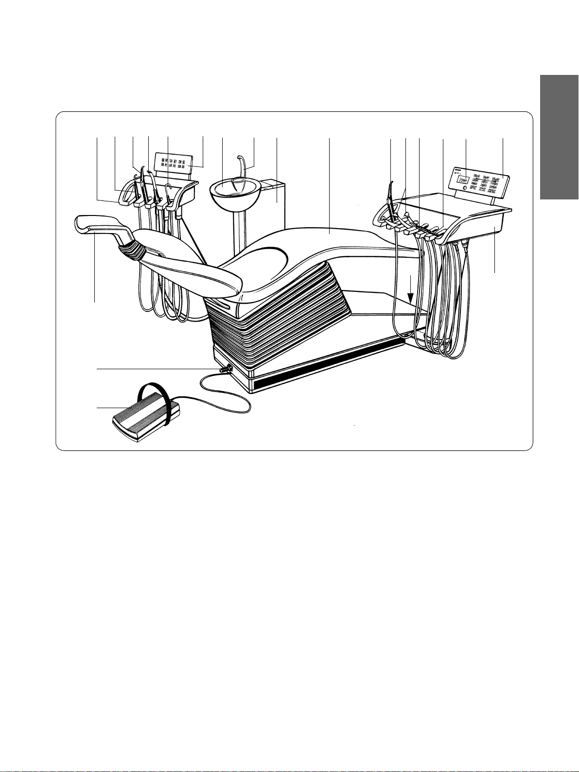
1 Bedien- und Funktionselemente
1
18
17
Bedien- und Funktionselemente
2
1
4
3
5
6
879
10
11 12
13 14
15
16
HIYXWGL
20
21
19
1 Helferinelement
2 POLYLUX - Kaltlicht
3 SPRAYVIT im Helferinelement
4 Saughandstück
5 Speichelsauger
6 Bedienfeld am Helferinelement
7 Speischale
8 Mundglasfüller
9 Wassereinheit mit Amalgamrotor
und Desinfektionsanlage
10 Patientenstuhl
11 SPRAYVIT im Arztelement
12 Bohrantriebe SIRONA-Motor / Turbine
13 SIROSON L Zahnsteinentfernungsgerät
14 SIROTOM Elektrochirurgiegerät
15 Display
16 Bedienfeld am Arztelement
17 Motorisch verstellbare Kopfstütze
18 Stuhl-Kreuzfußschalter
19 Gerätefußschalter
20 Gerätehauptschalter
21 Arztelement
41 63 189 D 3311
D 3311.201.01.10.01
7
Page 12

2 Arztelement
g
g
Sirona Dental Systems GmbH
2
Arztelement
C2
DESINF
AMALG
A
RPM
AMALG
DESINFA
RPM
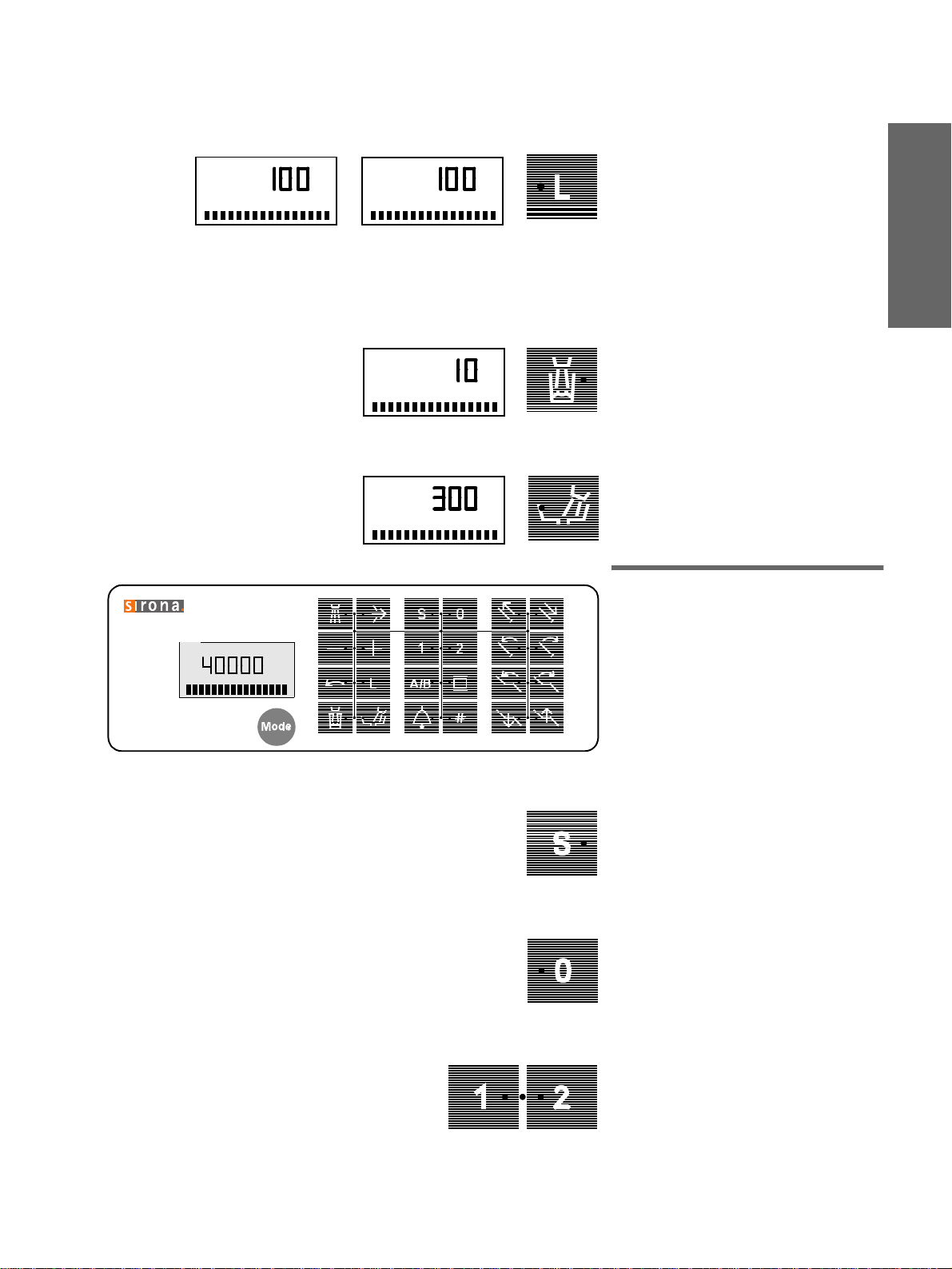
Bedienfeld
2.1 Display für die Anzeige
des Gerätezustandes
AMALG
rotor getauscht werden muß.
DESINF
nachgefüllt werden muß.
Taste
Grundeinstellungen.
erscheint, wenn der Amalgam-
blinkt, wenn
zum Programmieren von
Mode
DENTOSEPT P
A
SPRAY INTEN.
A
BLASLUFT
2.2 Funktion der Tasten
(linker Block)
Spray JA / NEIN
%
%
an Bohrantrieben (Fußschalter nach links).
Bei längerem Betätigen erscheint der Einstell-Dialog
Chip Blower JA / NEIN
an Bohrantrieben (Fußschalter nach rechts).
Bei längerem Betätigen erscheint der Einstell-Dialog
/ + für verschiedene Einstellungen.
–
• Drehzahl bei SIRONA-Motoren.
• Intensität bei SIROSON L.
• Intensität bei SIROTOM.
• Beleuchtun
ten und bei der Gerät eleuc hte.
• Arbeitsplatz-Voreinstellu n
SPRAY- INTEN
BLASLUFT
sintensität bei In strume n-
sität.
-Stärke.
en in Mode.
Linkslauf
8
bei SIRONA-Motor.
41 63 189 D 3311
D 3311.201.01.10.01
Page 13
Sirona Dental Systems GmbH
A
INSTR – LICHT
2 Arztelement
Licht EIN / AUS
%
A
OP – LICHT
%
Bei entnommenem Instrument:
Instrumenten-Licht
INSTR – LICHT
Bei abgelegten Instrumenten:
Geräteleuchte
OP – LICHT
.
.
Bei längerem Betätigen erscheint der entsprechende
tensität
Einstell-Dialog für die Lichtin-
.
HIYXWGL
Automatische Mundglasfüllung
A
BECHERFUELLZEIT
Bei längerem Betätigen erscheint der Einstell-Dialog
BECHERFUELLZEIT
.
Speischalenrundspülung
A
RUNDSPUELZEIT
Bei längerem Betätigen erscheint der Einstell-Dialog
RUNDSPUELZEIT
.
A
C2
AMALG
DESINF
RPM
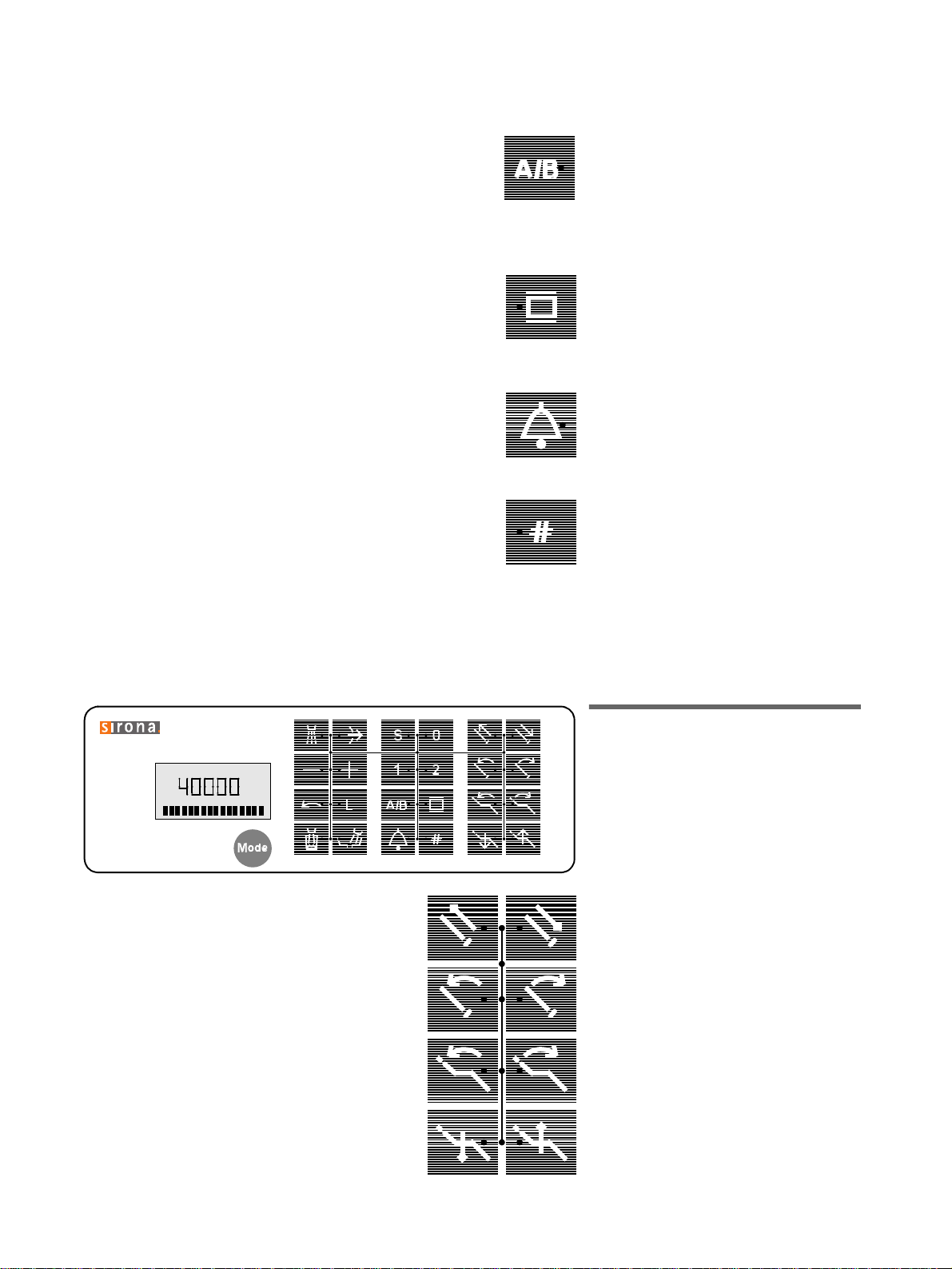
2.3 Funktion der Tasten
(mittlerer Block)
Bedienfeld
Stuhlprogramm Mundspülposition
mit Memory-Funktion
(frei belegbar)
Stuhlprogramm 0
Ein-/Aussteigeposition
(frei belegbar)
.
,
.
41 63 189 D 3311
D 3311.201.01.10.01
Stuhlprogramme 1 und 2
(
frei belegbar)
.
HINWEIS: Mit den vier Programmtasten
erfolgt auch die Programmierung.
9
Page 14
2 Arztelement
Sirona Dental Systems GmbH
Vorwahl des
(wird im Display angezeigt)
Behandlers A oder B
.
Bei gezogenem Instrument zur Speicherung der Instrumenteneinste llu nge n.
(Der Behandler kann bei gezogenem
Instrument nicht gewechselt werden)
Röntgenfilmbetrachter EIN / AUS
.
.
Funktion freier Wahl
z. B. Ruftaste (Funktion immer als Taster,
Anschluß durch den Techniker).
Funktion freier Wahl
z. B. Lichtreduzierung für Deckenleuchte
bei Komposit-Füllungen (Anschluß durch
den Techniker).
Die Funktion kann i n
als Taster oder
Mode
Schalter vorgewählt werden.
A
C2
AMALG
DESINF
RPM
oder Taste SIVISION
Diese Funktion kann in
Mode
vorgewählt
werden (dann nur Taster).
2.4 Funktion der Tasten
(rechter Block)
Bedienfeld
für manuelle Stuhleinstellungen:
Kopfstütze
Kopfstützen-Neigung
nach hinten oder vorne.
Stuhloberteil-Neigung
nach hinten oder vorne.
ausfahren / einfahren
10
Höhenverstellung
ab / auf
41 63 189 D 3311
D 3311.201.01.10.01
Page 15
Sirona Dental Systems GmbH
g
g
3 Hauptschalter
3
Hauptschalter
EIN
A
BEREIT
10:04:27
AUS
Hauptschalter
Nach dem Einschalten läuft die Selbstdiagnose des Behandlungsplatzes automatisch ab.
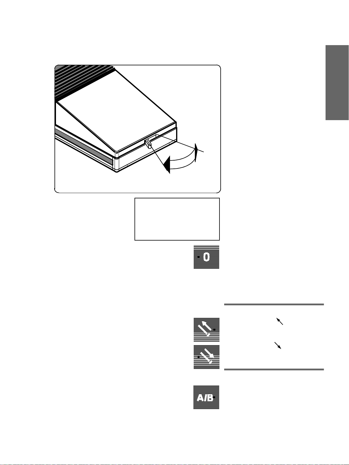
ACHTUNG!
Nach Ende der Sprechstunde bitte den
Behandlungsplatz aus Sicherheitsgründen unbedingt AUSschalten (O).
Der Behandlungsplatz muß sich vor
dem AUSschalten in der Ein-/ Aussteigeposition befinden.
Nach Ablauf der Selbstdia
auf dem Display die Meldung
Uhrzeit
den und der zuletzt
A
Die grüne LED der Taste 0 leuchtet auf
dem Bedienpaneel von Arzt und Helferin.
(Die Cursordiode befindet sich zwischen
den Tasten für Kopfst ütze ein-/ ausfahren).
Lassen Sie den Patienten auf dem Stuhl
Platz nehmen.
ACHTUNG: Belastbarkeit des Stuhles
max. 135kg! Arme und Beine des Patien ten müssen
in Stunden, Minuten und Sekun-
oder B.
schalten ( l ).
EIN
nose erscheint
BEREIT
ewählte Behandler
auf
dem Stuhlpolster ruhen!
, die
HIYXWGL
41 63 189 D 3311
D 3311.201.01.10.01
3.1 Kopfstütze anpassen
Kopfstütze ausfahren
Kopfstütze einfahren
Hygieneschutz für Kopfstütze und Kinder-
sitzpolster siehe Seite 20.
3.2 Behandler vorwählen
Wenn zwei Personen mit diesem Behandlungsplatz arbeiten:
Behandler A oder B vorwählen.
Der vorgewählte Behandler wird im Di splay
oben links angezeigt. Die für diesen
Behandler gespeicherten Einstellungen
stehen dann zur Verfügung.
11
Page 16
4 Amalgamrotor, Desinfektionsanlage
Sirona Dental Systems GmbH
4
Amalgamrotor, Desinfektionsanlage
4.1 Amalgamrotor
A
AMALG
RPM
Die Anzeige
Amalgamrotor ausgetauscht werden muß
(siehe
Ein Dauerton
gefüllt ist und nicht mehr arbeitet.
Ein Intervallton
Wasserzufuhr wird unterbrochen. Rufen
Sie bitte Ihren Techniker.
HINWEIS:
befindliche Rotor muß unabhängig vom
Aufleuchten der Anzeige
stens einmal pro Jahr getauscht werden,
andernfalls können unangenehme
Geruchsentwicklungen entstehen.
AMALG
Wartungsanweisung
zeigt an, daß der Rotor
Der im Amalgamabscheider
4.2 Desinfektionsanlage
Die Desinfekti onsanlage setzt dem Wasser
ein Desinfektionsmittel zu (1:100), das die
Bildung von Mikroorganismen in den Wasserwegen verhindert.
4.3 Vor der
Erst-Inbetriebnahme
Ihres Behandlungsplatzes muß eine
Sanierung
Wurde die Sanierung, nac h Abspra che mi t
Ihnen, nicht zum Abschluß der Montage
A
DESINF
RPM
Ihres Behandlungsplatzes vom Techniker
durchgeführt, tun Sie dies bitte anha nd der
separaten
Die Sanierung dauert ca. 24 Stunden.
durchgeführt werden.
Wartungsanweisung
erscheint, wenn der
).
zeigt einen Fehler an . Die
AMALG
minde-
.
12
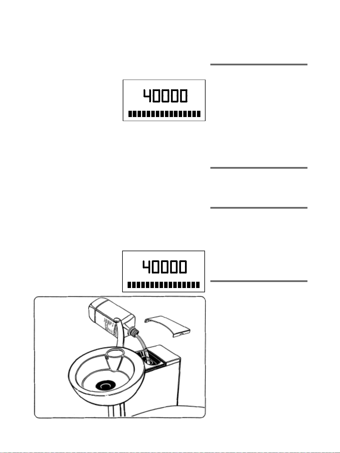
4.4 Während der Behandlung
Blinkt während der Behandlung auf dem Display am Arztelement die Anzeige
ist vor der Behand lung de s nächst en Patien ten 1 Liter
Nehmen Sie die Abdeckung hinter der
Speischale ab und füllen 1 Liter
DENTOSEPT P
Die
Lassen Sie
Einfüllmulde gelang en!
DENTOSEPT P
1 Karton = 6x1 Liter, Bestell-Nr. 33 18 156
Mikrobiologische Kontrolle des Wassers
(nach mehr als
Sanierung des Arbeitsplatzes
Die Sanierung ist alle
ren. Nur so kann sichergestellt werden, daß
Biofilm in den Wasserwegen wirksam
bekämpft wird.
siehe Wartungsanweisung.
DENTOSEPT P
Einfüllmulde
kein Leitungswasser
1 Woche
ein.
bitte
4 Wochen
sauber halten
DESINF
nachzufüllen:
Arbeitspause)
durchzufüh-
41 63 189 D 3311
D 3311.201.01.10.01
, so
.
in die
Page 17
Sirona Dental Systems GmbH
5 Fußschalter
5
B*
Fußschalter
C
S
A*
D
Die Funktionen können
schalter
der Tasten
ment
Am Helferinelement kön nen die Funktionen
nur manuell
Bei Anwahl mit dem Fußschalter
der Fuß ganz auf die Pedaloberfläche
gestellt werden.
Die gelbe Diode am Arztelement zeigt die
Position des Cursors an.
, oder
von Hand durch Betätigen
auf dem Paneel am Arztele-
angewählt werden.
angewählt werden.
mit dem Fuß-
muß
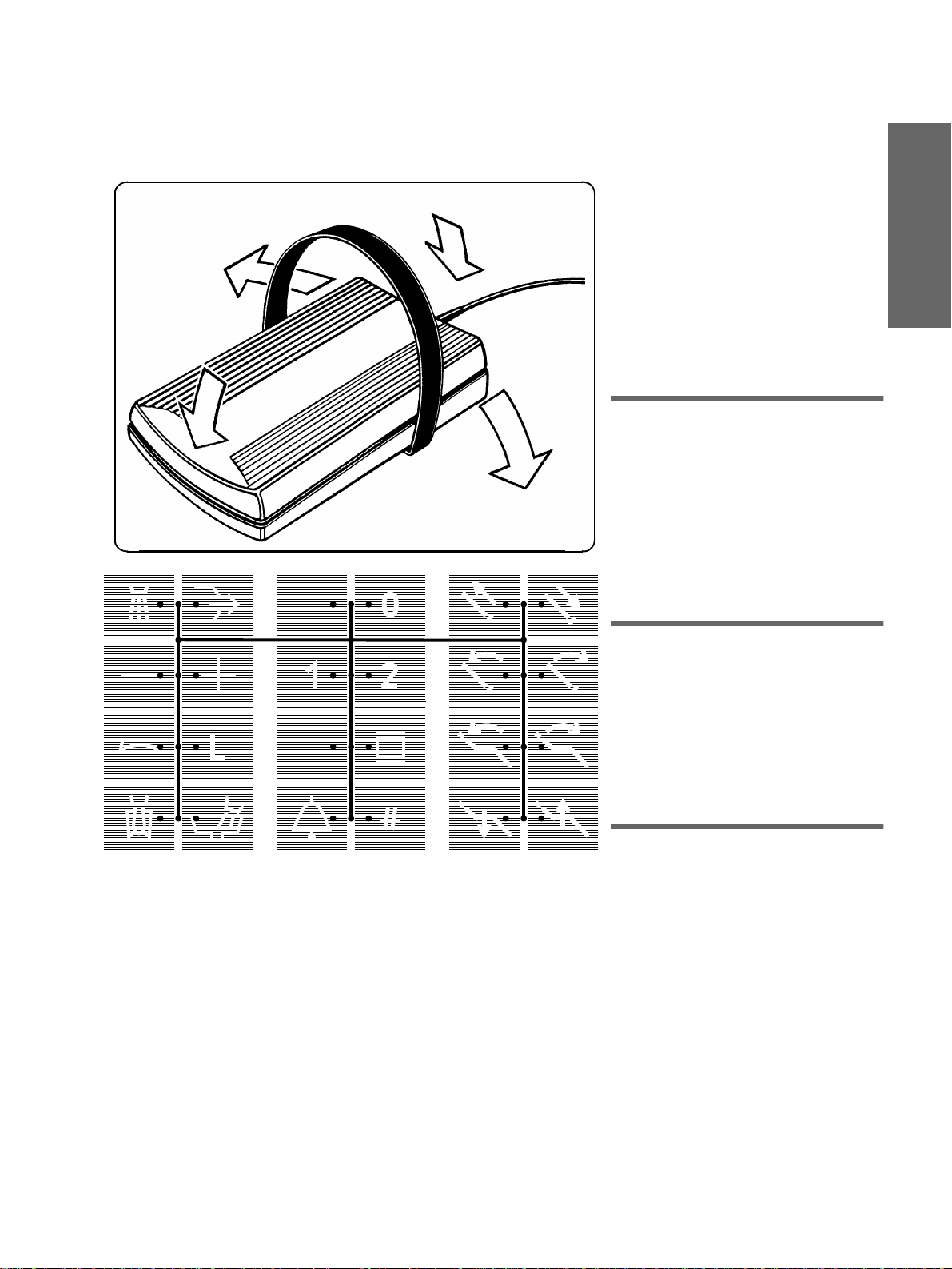
5.1 Funktionen vorwählen
Fußschalter betätigen (Werkseinstellung) *
: Cursordiode springt
bei
A
bei B: Cursordiode springt
Wenn die gelbe Cursordi ode zwisch en den
beiden oberen Tastenr eihen leuchtet, kann
durch
(→ D
ken
den Tastenblöcken gewechselt werden.
Der Cursorpfad ist durch Linien markiert.
- (C←) bzw.
Links
der Pedaloberfläche zwischen
)
nach oben
nach unten
Rechtsschwen-
↑
↓
HIYXWGL
A/B
5.2 Funktionen auslösen
Leuchtet die gelbe Cursordiode zwischen
zwei nebeneinander lieg end en T as ten ,
kann durch
che nach
links (C ←) oder rechts (→ D
chende Funktion ausgelöst werden.
Die grüne Diode der ange wählten Funktion
leuchtet dann auf.
Schwenken
der Pedaloberflä-
die entspre-
)
5.3 Arztelement heranfahren
bzw. wegfahren.
Das
Einstiegsprogramm 0
Der Cursor
Tasten
Durch Betätigen des Fußschalters bei A*
fährt das Arztelement in Richtung Behandler (wenn umgestellt, in R icht ung Fuße nde
des Patienten). Nach Entlasten des Fußschalters bleibt das Arztelement stehen,
der Cursor springt zwischen Stuhlprogramm 1 und 2 und, wenn in
wählt, wird auch die Geräteleuchte
SIROLUX FANTASTIC
schaltet (Mode-Punkt 12.17).
Ein Stuhlprogramm kann sofort angefahren
werden.
befindet sich zwischen den
Kopfstütze ein-/ausfahren
ist angezeigt.
.
vorge-
Mode
automatisch einge-
41 63 189 D 3311
D 3311.201.01.10.01
13
Page 18

5 Fußschalter
Sirona Dental Systems GmbH
HINWEIS:
Bei ausgeschaltetem Cursor
(Mode-Punkt 12.6)
wenn also die Funktionen nur von Hand
durch Betätigen der Tasten auf dem
Paneel am Arzteleme nt angewählt w erden:
Das Gerät fährt dann, wenn alle Instrumente in ihren Köchern abg elegt sind,
durch Treten und getreten halten des Fußschalters bei B* wieder in die Ausgangsposition zurück.
,
5.4 Behandlungsinstrument
starten
Der Start eines gezogenen Instruments
erfolgt durch Betätigen des Fußschalters
bei
.
*
A
*
Die Fußschalterfunktionen A und B
können auf Wunsch durch den ServiceTechniker getauscht werden.
14
41 63 189 D 3311
D 3311.201.01.10.01
Page 19
Sirona Dental Systems GmbH
6 Patientenpositionen, Programmauswahl
6
Patientenpositionen,
Programmauswahl
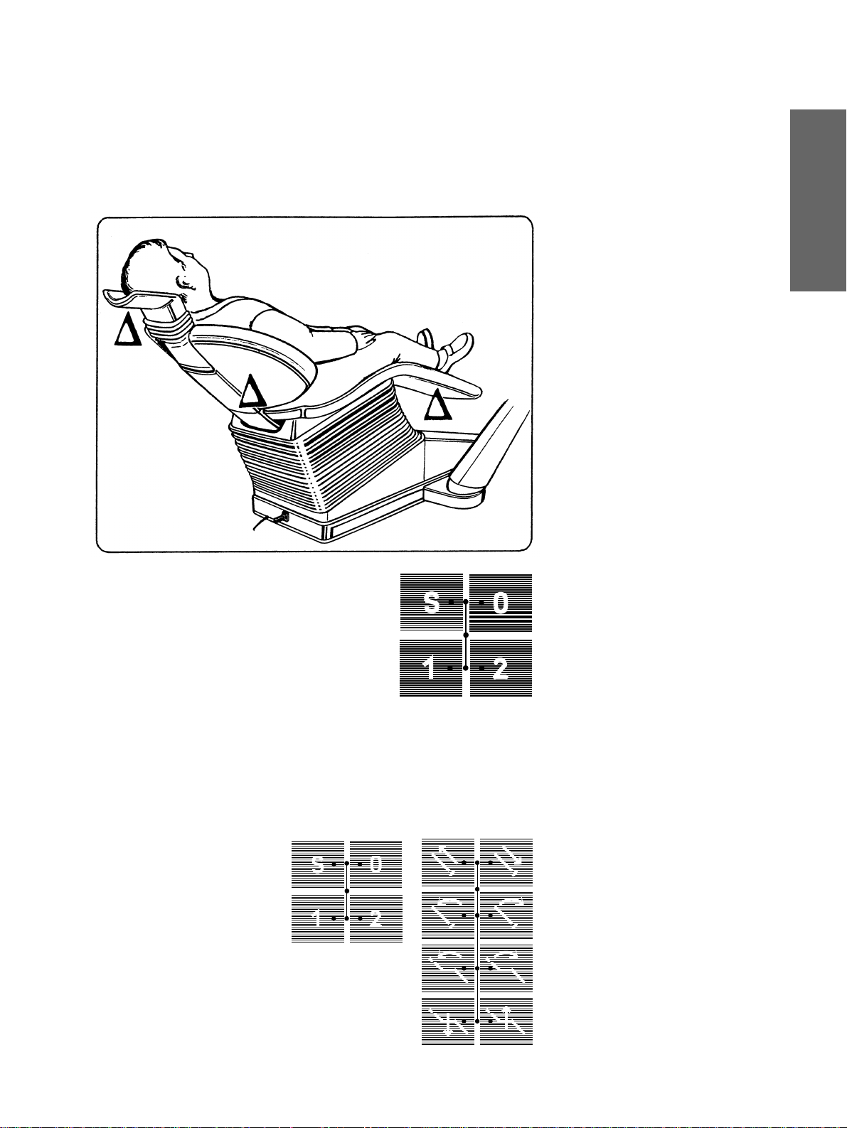
ACHTUNG!
Während des Programmablaufs müs sen
auf
Beine und Arme des Patienten
Stuhlpolster ruhen!
HINWEIS: Eine eingebaute Sicherheitsschaltung
wenn die Sitzschalenunterseite ∆, die Rükkenlehne ∆ oder die Kopfstütze ∆ auf ein
Hindernis auffährt.
Der Stuhl fährt danach automatisch ein
Stück nach oben, bis das H indernis wiede r
frei wird.
stoppt die Stuhlbewegung,
dem
HIYXWGL
Tasten für
Patientenpositionen
Werkseinstellung:
Vor der Fahrt in die Ein-/ Aussteigeposit ion
oder in die Mund spülpositi on S schaltet
0
die Geräteleuchte automatisch
Nach Erreichen der Patientenposition
bzw. 2 schaltet die Geräteleuc hte auto -
1
matisch
Verändern der Werkseinstellung:
Ob die Geräteleuchte bei den verschiedenen Stuhlprogrammen 0, S, 1 oder 2 AUSoder EINschalten soll , kann beim Prog rammieren der Patientenpos itionen vorgewählt
werden (siehe Seite 18).
BEWEGUNGSSTOP!
Während der Fahrt in die automatisch
ablaufenden Programme können durch
Aktivieren einer der den Stuhl betreffen den Tasten sämtliche Bewegungen des
Arbeitsplatzes sofort angehalten werden.
Dabei ertönt ein doppeltes akustisches
Signal.
Abruf der programmierten
.
AUS.
.
EIN
41 63 189 D 3311
D 3311.201.01.10.01
15
Page 20

6 Patientenpositionen, Programmauswahl
Sirona Dental Systems GmbH
Programmtaste 0
für Ein-/Au ssteigeposition.
Programmtaste S
mit Memory-Funktion.
Durch ein z weites Aktivieren dieser Taste
fährt der Behandlungsplatz in die zuletzt
eingenommene Position zurück (MemoryFunktion).
Beispiel:
Sie haben in diese Taste die
Mundspülposition programmiert. Nach
Aktivieren
dieser Taste fährt der Behand-
lungsplatz in die programmierte Stellung.
Die Memoryfunktion: Ei n zweites Aktivieren
dieser Taste läßt den Behandlungsplatz in
die zuletzt e ingen omme ne Posit ion zurück fahren.
16
41 63 189 D 3311
D 3311.201.01.10.01
Page 21

Sirona Dental Systems GmbH
7 Patientenpositionen, manuelle Einstellung
7
Patientenpositionen,
manuelle Einstellung
Mit den Tasten im rechten Block auf dem
Bedienfeld des Arztelements können Sie
die einzelnen Stuhlbewegungen manuell
auslösen.
Kopfstütze ausfahren .
Kopfstütze einfahren .
Kopfstützen-Neigung nach hinten .
Kopfstützen-Neigung nach vorne .
HIYXWGL
Stuhloberteil-Neigung nach hinten .
Stuhloberteil-Neigung nach vorne
Die Oberteil-Neigung kann auch mit dem
Kreuzfußschalter ← → erfolgen.*
Schalthebel nach links ← :
Oberteilneigung nach hinten .
Schalthebel nach rechts → :
Oberteilneigung nach vorne .
Höhenverstellung ab ↓.
Höhenverstellung auf ↑.
Die Höhenverstellung ka nn auch mit dem
Kreuzfußschalter erfolgen.*
Schalthebel nach oben ↑ :
Stuhl fährt nach oben.
Schalthebel nach unten ↓ :
Stuhl fährt nach unten.
*
HINWEIS: Da mit dem Kreuzfußschalter
auch ein im Helferinelement eingebautes
POLYLUX-Licht ein- bzw. ausgeschaltet
werden kann, muß das POLYLUX-Licht
beim Schalten der Stuhlfunktionen im
Köcher abgelegt sein.
.
41 63 189 D 3311
D 3311.201.01.10.01
17
Page 22

8 Patientenpositionen programmieren
g
(
g
g
g
g
g
gung
gung
g
g
g
g
g
Sirona Dental Systems GmbH
8
Patientenpositionen programmieren
Stuhl und Arztelement
Die vier werkseitig eingestellten Programme können von den Behandlern A
und B individuell neu belegt werden.
(Überschreiben der Werksvorg abe).
Programme 1 und 2 (frei belegbar)
Ein-/Aussteige-Programm 0.
Mundspül-Programm S .
• Fahren Sie den Stuhl durch Aktivieren
der verschiedenen Einstelltasten in di e
von Ihnen
position
• Wenn Sie wünschen, daß nach Erreichen der programmierten Behandlun
SIROLUX F ANTASTIC einschalten
bzw. ausbleiben soll, so müssen Sie
nun die Leuchte E IN- bz w. AUSschalten.
Diese Einstellun
rammiert.
• Brin
Hand in die von Ih nen
Griffposition.
ACHTUNG: Um Beschädi
Arzt- und Helferinelement s owie am
Stuhlpolster zu vermeiden, achten
Sie bitte darauf, daß diese Elem ente
nicht in den Bewe
Stuhles
• Um die Pro
speichern, drücken Si e die
Pro
ein akustisches Si
Die Programmierung ist abgeschlos sen.
ewünschte Behandlungs-
siehe Seite 17).
sposition die Geräteleuchte
wird dann mitpro-
en Sie nun das Arztel ement von
ewünschte
en am
sbereich des
elangen.
rammeinstellungen zu
ewünschte
rammtaste ca. 5 Seku nden, bis
nal ertönt.
HINWEIS: Die Programmierung kann
nicht durch Aktivieren der Programmtasten mit dem Fußschalter (Cursorsteuerung) erfolgen.
Dadurch werden Fehlprogrammierungen vermieden.
41 63 189 D 3311
18
D 3311.201.01.10.01
Page 23
Sirona Dental Systems GmbH
8 Patientenpositionen programmieren
Beim Programmieren der Taste S besteht
die Möglichkeit, die
und / oder die
mit zu programmieren.
Mundglasfüllung
Speischalenrundspülung
A
MUNDGLAS BEI S
JA – NEIN
A
RUNDSPUEL. BEI S
JA – NEIN
Dazu die Taste
die Anzeige
RUNDSPUEL. BEI S
Mit den – / + Tasten so einstellen, daß
blinkt.
JA
Beim Abruf
schaltet dann, wenn programmiert, au tomatisch auch die
und / oder die
ein.
Memory-Funktion
Ein zweites Aktivieren dieser Taste läßt
den Arbeitsplatz in die zuletzt eingenommene Position zurückfahren.
MUNDGLAS BEI S
der
so oft betätigen, bis
Mode
bzw.
erscheint.
Mundspülposition S
Mundglasfüllung
Speischalenrundspülung
HIYXWGL
41 63 189 D 3311
D 3311.201.01.10.01
Beim Aktivieren des
der Behandlungsstuhl in die programmierte
Ein-/Aussteigestellung
Der Cursor springt zwisch en die Tasten für
Kopfstütze ein-/ ausfahren.
Programms 0
.
fährt
19
Page 24
8 Patientenpositionen programmieren
)
(
)
Sirona Dental Systems GmbH
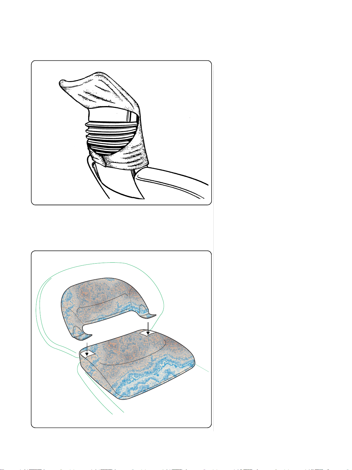
Kopfstütze
Hygieneschutz für Kopfstütze
Zubehör
Es stehen zwei Kopfschutztaschen für die
Kopfstütze des Patientenstuhls zur Verfügung:
• Kopfschutztasche aus Stof f,
waschbar mit Klettvers chluß
Bestell-Nr . : 14 32 801 (5 Stück
• Kopfschutztasche, Einwegartikel
mit Selbstklebeversch luß
Bestell-Nr . : 14 32 868
Kopfschutz tasche wie gezeigt an der Kopfstütze anbringen.
5 Stück
Kinder-Sitzpolster
Zusatzausstattung
Zweiteilig, Best. Nr.: 54 46 062 D 3264
Rückenteil ist mit Klettverschluß befestigt
und kann abgenommen werden.
Bezugstoff: 100% Baumwolle,
Scotchgardausrüstung.
Pflegehinweis:
Scotchgard ausrüstung Schmutz- und Nässeabweisend.
Evtl. Verschmutzungen mit lauwarmer
Seifenlauge ( Feinwaschmittel ) entfernen.
Fleckentfernung mit Fleckenwasser
nicht geeignet, da Scotchgardausrüstung beschädigt wird!
Der komfortable Sitz wird einfach auf das
Stuhlpols ter aufgesetzt.
Damit ist auch für Kinder eine gute
Lagerung des Kopfes auf der motorisch
verstellbaren Kopfstütze möglich.
Die Kinder-Kopfstütze wird dann nicht
mehr benötigt.
20
41 63 189 D 3311
D 3311.201.01.10.01
Page 25

Sirona Dental Systems GmbH
9 Fußschalterart vorwählen
9
Fußschalterart vorwählen
Die gewünschte Voreinstellung des Fußschalters als
schalter
ler A oder B in
Dazu die Taste
die Anzeige
A
FUSSSCHALTER
EIN / AUS – REGELBAR
FUSSSCHALTER
EIN / AUS − REGELBAR
Dann mit den
terart wählen. Die blinkende Art ist vorgewählt.
Bei
Flachstarter-Voreinstellung
sich der Schwellbalken nach dem Betätigen des Fußschalters immer gleich auf
dem maximalen Wert. Sie arbeiten mit dem
angezeigten Höchstwert.
Bei
Regelfußschalter-Voreinstellung
schwillt d er Balken an.
Sie arbeiten im Bereich von 0 bis zum
angezeigten Höchstwert.
Flachstarter
erfolgt individuell für den Behand-
Mode
Mode
/ + Tasten die Fußschal-
–
oder
Regelfuß-
.
so oft betätigen, bis
erscheint.
befindet
HIYXWGL
41 63 189 D 3311
D 3311.201.01.10.01
21
Page 26
10 Instrumentenfunktionen
Sirona Dental Systems GmbH
10
Instrumentenfunktionen
Nach Entnahme eines Instrum entes springt
der Cursor in den linken Tas te nbl oc k g anz
nach oben.
Durch Aktivieren der Taste
NEIN
Spraykühlung vorgewählt werden.
Ist
A
%
SPRAY INTEN.
A
%
BLASLUFT
grüne LED in der Taste.
Wird die Taste länger als 3 Sek. aktiviert,
erscheint der Einstell-Dia lo g
INTEN
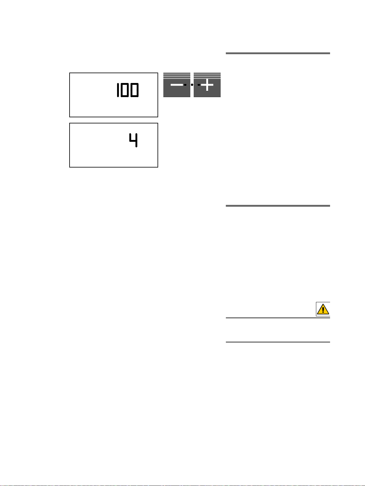
Die Spraymenge kann h ier m it den Tas ten
/ + von 0 bis
–
Bei einer Einstellung < 20% wird nur noch
mit Luft gekühlt. Die Luftk ühlung ni mmt zu,
je geringer der Wert ist.
Wenn der Cursor bei entnommenem Bohrinstrument* neben der
steht und der Fußschalter nach rechts
betätigt wird, tritt an der Düse des Bohrinstrumentes ein Luftstrahl aus.
Wird die Taste länger a ls 3 Seku nden vo n
Hand gedrückt, e rscheint de r Einstelldialog
für die Stärke der
hier mit den Tasten
eingestellt werden.
Spray JA /
(oder Fußschalter nach links)
Spray JA
vorgewählt, leuchtet die
sität.
eingestellt werden.
100%
Chip blower
BLASLUFT
/ + von 50 bis
–
kann
SPRAY -
-Taste
. Diese kann
100
%
22
A
INSTR. LICHT
%
Mit der Taste L (oder Fußschalter nach
rechts)
wählen Sie
EIN / AUS
vor*.
Ist
grüne LED in der Taste.
Wird die Taste länger als 3 Sek. aktiviert,
erscheint der Einstell-Dia lo g
tät INSTR. LICHT
Tasten
werden.
Bei mehreren entnommenen Instrumenten ist
*
nur das zuerst entnommene Instrument betriebsbereit.
für das entnommene Instrument
Licht EIN
/ + von 60 bis
–
Instrumentenlicht
vorgewählt, leuchtet die
Lichtintensi-
. Diese kann hier mit de n
% eingestellt
100
41 63 189 D 3311
D 3311.201.01.10.01
Page 27
Sirona Dental Systems GmbH
10 Instrumentenfunktionen
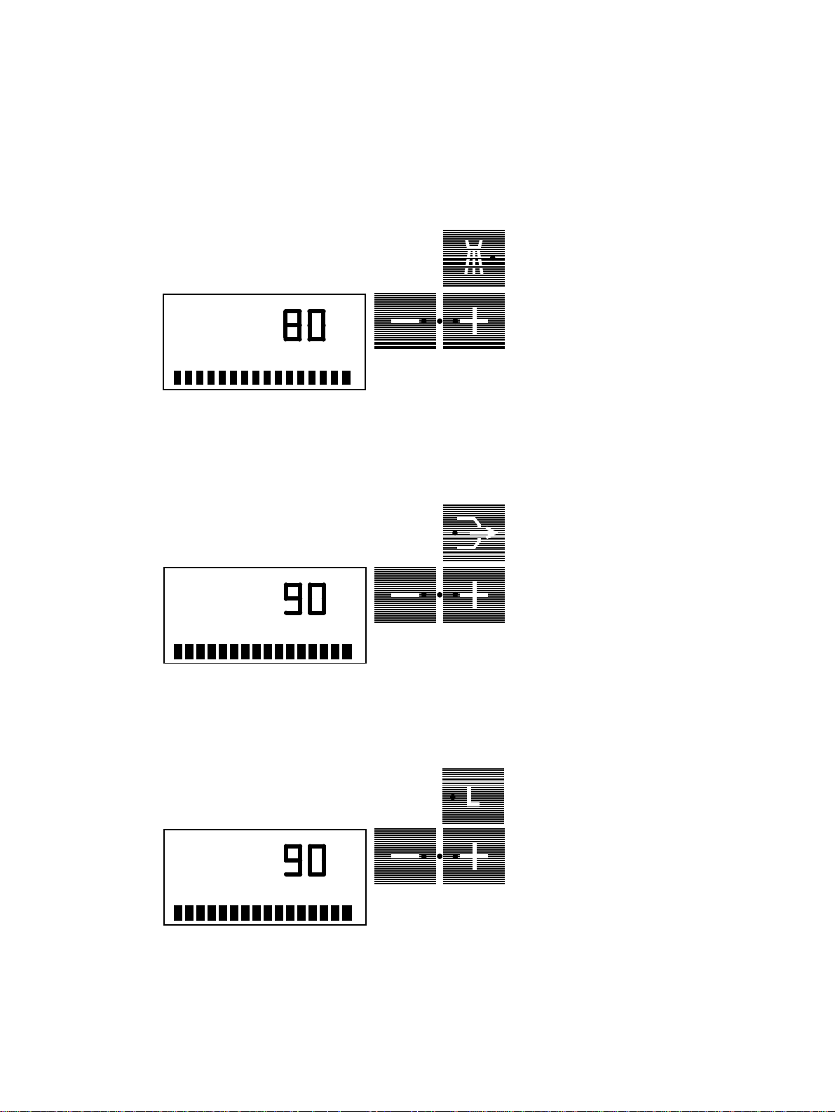
10.1 SIRONA-Motor
Nach Entnahme und Starten eines
A
RPM
SIRONA-Motors
die einprogrammierte Drehzahl des Motors
in
und der Behandler A bzw. B.
RPM
Die Drehzahleinstellung erfolgt mit den
/ + Tasten.
–
Wenn Sie die entsprechende Taste
gedrückt halten
zahl in Zählschritten:
Zählschritte 200: Von 200 − 2000 min
Zählschritte 400: Von 2000 − 10000 min
Zählschritte 1000: Von 10000 − 40000 min
Schnelleinstellung:
Bei
kurzem Antippen
springt die Drehzahlvorwahl immer jeweils
zum nächsten 10000er Schritt nach oben
oder nach unten.
erscheint auf dem Display
, verstellen Sie die Dreh-
−
1
−
1
der jeweiligen Taste
HIYXWGL
−
1
A
A
DRUCK
PSI / BAR
bar
PSI
Linkslauf
(Fußschalter nach links). Wenn diese
Taste aktiviert ist, leuchtet di e grüne LED
der Taste.
Nach dem Start des SIRONA-Motors mit
dem Fußschalter ertönt ein 6maliges akustisches Warnsignal.
-Taste, nur für
SIRONA-Motor
10.2 Turbine
Nach Entnahme der Turbine erscheint auf
dem Display 0 bar bzw. PSI (je nach Voreinstellung). Beim Starten und Betreiben der Turbine erscheint auf dem Display immer der
aktuelle Luft druc k in bar bzw. PSI.
Der maximale Luftdruck der Turbine wird über
/ + Tasten bei laufender Turbine bis
die
–
zum in Mode eingestellten höchst zulässigen
Wert geregelt.
Wenn Sie die entsprechende Taste
, verstellen Sie den Luftdruck in Zähl-
halten
schritten von 0,1 bar bzw.1 PSI.
Die Voreinstellung BAR bzw. PSI erfolgt mit
der
Mode-Taste so oft drücken, bis auf dem
Display
Dann mit den
gewünschte Druckangabe wählen.
Die blinkende Angabe ist vorgewählt.
-Taste.
Mode
DRUCK, PSI / BAR
/ + Tasten die
–
gedrückt
erscheint.
41 63 189 D 3311
D 3311.201.01.10.01
23
Page 28
10 Instrumentenfunktionen
A
A
ENDO MAX. 4%
%
%
Sirona Dental Systems GmbH
10.3 SIROSON L
Nach Entnahme und Starten des
SIROSON L
dem Display der einprogrammierte Intensitätswert in % und der Behandler A bzw. B.
Die Einstellung der Intensität erfolgt mit
den
–
Wird die entsprechende Tas te
gehalten
Zählschritten:
1%: 1 – 4%
5%: 10% – 100 %
Schnelleinstellung:
Bei kurzem Antippen der jeweiligen Taste
springt der Wert in 20% Schritten nach
oben oder nach unten weiter.
Der Kühlwasserdurchfluß ist automatisch
immer zugeschaltet.
- Handstückes erscheint auf
/ + Tasten von 1% bis 100%.
gedrückt
, verstellen Sie die Intensität in
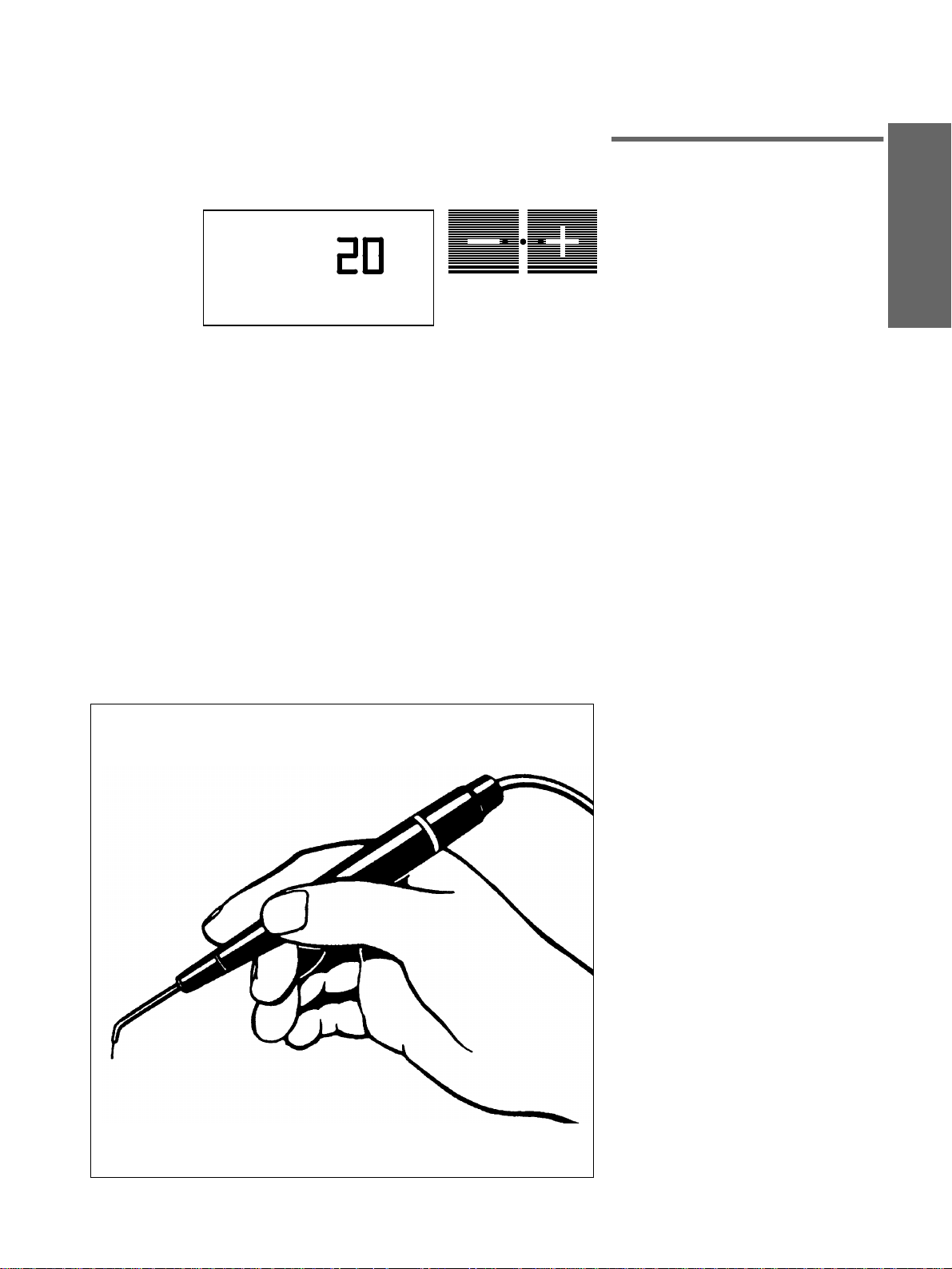
10.4 SIROSON L − Endodontie
Der Intensitätsbereich 1–4% ist für Endodontie vorgesehen. Er ist in 1% Schritten
einstellbar.
Dabei erscheint auf d em D isp lay d er Warn hinweis
Aus Sicherheitsgründen empfehlen wir,
den eingestellten Wert für Endodontie zu
programmier en. Ansonst en ist beim zwischenzeitlichen Abl egen de s Instru mente s
in der Klaue der bisher programmierte Wert
wieder aktiv.
ENDO MAX. 4%
ACHTUNG
Beim Überschreiten v on 4 % bei En dodontie-Behandlung können Temperaturschäden und Nadelb rüc he auftre ten.
.
24
41 63 189 D 3311
D 3311.201.01.10.01
Page 29
Sirona Dental Systems GmbH
10 Instrumentenfunktionen
10.5 SIROT OM HF-Elektro-
chirurgie
A
Nach Entnahme des
kes erscheint auf dem Display der einprogrammierte Intensitätswert und der
Behandler A bzw. B.
Der Fußschalter ist automatisch auf
Flachstarterbetrieb eingestellt.
Die Einstellung der Intensität erfolgt mit
den
/ + Tasten von 1 bis
–
Wird die entsprechende Tas te
gehalten
Schritten:
1 Schritt: von 1 – 10
5 Schritte : von 10 – 100
Schnelleinstellung:
Bei
springt der Wert in 20er Schritten nach
oben oder nach unten weiter.
, verstellen Sie die Intensität in
kurzem Antippen
SIROTOM
der jeweiligen Taste
-Handstük-
.
100
gedrückt
HIYXWGL
HF-Elektrochirurgie
Mit dem Elektrochirurgie-Handstück können Elektrotomie (sc hneiden), Koag ulation
und Desiccation, in biterm ina ler Tec hni k
durchgeführt werde n.
41 63 189 D 3311
D 3311.201.01.10.01
25
Page 30

10 Instrumentenfunktionen
Neutrale
Elektrode
Aktive
Elektrode
Sirona Dental Systems GmbH
ACHTUNG
Dabei muß immer die Neutralelektr ode
vom P atienten in de r Hand gehalten werden!
Die Anschlußbuchse befindet sich auf der
Unterseite des Arztelements.
Das Handstück wird durch Betätigen des
Fußschalters gestartet. Dabei ertönt ein
unterbrochenes akustisches Signal.
ACHTUNG
Aus funkschutztechnischen Gründe n
darf das Handstück nur im Sekundenbetrieb angewendet werden.
Bleibt der Fußschalter länger als eine
Minute getreten, schalt et das Gerät ab. Die
Einschaltung muß unterbrochen werden.
Nach Ablegen des Han dstücks schaltet di e
HF ab. Bei der nächsten Entnahme des
Handstücks erscheinen wieder die programmierten Werte der vorher gewählten
Behandlerebene.
ACHTUNG
Falsche Bedien ung und die Nic htbeac htung von Vorsichtsmaßregeln können
bei Anwendung des Elektr oc hirurg ieGerätes schwerwiegende Zwischenfälle
verursachen.
WARNUNG
Bei Patienten mit Herzschrittmachern besteht die Gefahr, daß der Herzschrittmacher
bei Behandlung mit dem Elektrochirurgie-Gerät gestört werden kann.
Wir empfehlen, bei diesen Patienten das
Elektrochirurgie-Gerät nicht zu benutzen.
26
41 63 189 D 3311
D 3311.201.01.10.01
Page 31

Sirona Dental Systems GmbH
10 Instrumentenfunktionen
Weitere WARNHINWEISE für das
Arbeiten mit dem Chirurgiegerät
• Der Patient sollte nicht m it Me talltei len
in Berührung komm en, di e gee rdet
sind oder beträcht liche Kapaz ität ge gen Erde haben (z. B . Operationst isch,
Halterungen).
• Die Leistungsabgabe sollte auf e inen,
für den jewei ligen Zw ec k, m öglic hst
niedrigen Wert eingestel lt w erden .
• Wenn das Chirurgiegerät scheinbar
wenig Leistung abgib t, oder bei normaler Einstellung ni cht ord nun gsgem äß
arbeitet, kann dies einen schlechten
Kontakt in der Zuleitung zur Ursache
haben.
• Brennbare Stoffe, die z. B . als Re inigungs- und Desinf ektionsm ittel v erwendet werden , sollten v or An wendung der Chirurgie verdu nstet sein.
Watte kann entz ündet
gene
Gase können gezündet werden.
werden. Endo-
HIYXWGL
Watt
50
40
30
20
10
• Die HF kann die Funktion ande rer elektronischer Geräte beeint rächti gen.
• Die Elekrodenleitung ist regelmäßig
auf mögliche Schäde n an der Isolat ion
zu prüfen.
Technische Beschreibung
SIROTOM Elektrochirurgie
Leistungskennlinie
für Schneiden und Koagulation
Leistung gemessen zwischen Handstück
und Erde.
Intensität=100
Intensität=50
41 63 189 D 3311
D 3311.201.01.10.01
500 1000
1500 Ohm
2000
27
Page 32

10 Instrumentenfunktionen
Watt
Sirona Dental Systems GmbH
Leistungskurve
für Schneiden und Koagulation
50
40
30
20
10
10
20
30
40
50
60 70
R=500
Ω
80 90 100
Leistung gemessen zwischen Handstück
und Erde.
Intensität
Technische Daten
SIROTOM Elektrochirurgie
Maximale Ausgangsspannung Spitze –
Spitze zwischen Handstück und Schutzleiter bei Schneiden un d Koagulation: 1500 V
Frequenz des Betriebs- und Alarmtons:
1200 Hz
PAB 25% ED 10s SD 40s
1MHz / 50W / 500 Ohm
Die Neutralelektrode ist über einen Kondensator an den Schutzleiter angeschlossen.
Anschluß für die Neutralelektrode.
Neutralelektrode bei Hochfrequenz auf
Erde bezogen.
SIROTOM Gerätetyp BF
Kurzzeitbetrieb 25%
Einschaltdauer 10s
Spieldauer 40s
HF-Frequenz 1MHz
Ausgangsleistung max. 50W an 500 Ohm
Bildzeichen für nicht ioni sierende Strahlun g
28
41 63 189 D 3311
D 3311.201.01.10.01
Page 33

Sirona Dental Systems GmbH
g
q
gäng
g
g
10 Instrumentenfunktionen
Sicherheitstechnische Kontrollen
nach MPG
Alle 12 Monate sind unter Beachtung von
DIN VDE 0751/10.90 folgende sicherheitstechnische Kontrollen durchzuführen:
• Sichtkontrolle von Gerät und Zubehör
auf funtionsbeeinträc hti
nische Schäden, insbeson dere der
Hochfre
• Kontrolle der von außen zu
Sicherun
• Generelle Funktionskontrolle
• Kontrolle der akustischen und optischen Anzeigen
• Schutzleiterprüfung nach DIN VDE
0751/10.90
•Messun
DIN VDE 0751/10.90
uenz-Leitungen.
en bezüglich der Nenndaten.
der Ersatzableitströme nach
ende mecha-
lichen
HIYXWGL
10.6 SPRAYVIT
A
Wird die SPRAYVIT entnommen , erscheint
auf dem Display nur der vor gewählte
Behandler A bzw. B.
Es kann nur Instrumentenlicht JA/NEIN
vorgewählt und die Helligkeit eingestellt
werden.
Das Instrumentenlicht schaltet bei Betätigen der SPRAYVIT ein (wenn vorgewählt ).
Es erlischt nach Ableg en des Hand stückes
wieder.
41 63 189 D 3311
D 3311.201.01.10.01
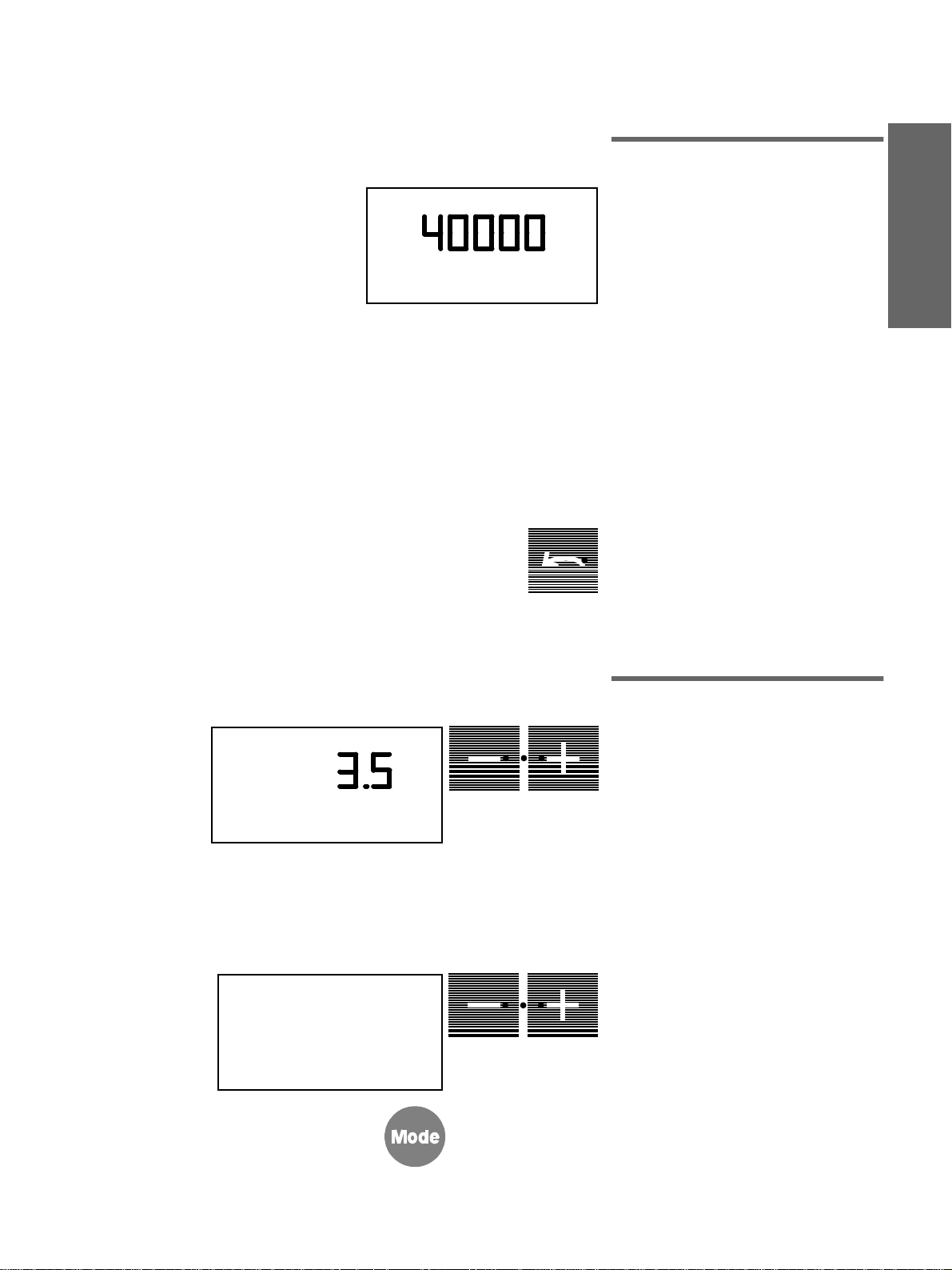
10.7 Feste Einstellungen
A
RPM
Entnehmen Sie ein Instrument und stellen
es nach Ihren Vorstellungen ein.
Beispiel SIRONA-Motor:
40 000 min
Rechtslauf
mit Kühlspray
mit Instrumentenlicht.
Durch längeres Drücken (ca. 3 Sek.) der
Taste
gespeichert. Es ertönt ein akustisches
Signal. Diese Einstellungen sind dann bei
jeder Instrumentenentnahme präsent.
Jeder Behandler A oder B kann für die einzelnen Instrumente individuelle Einstellungen speichern.
speichern
−1
werden die Einstellungen
A/B
29
Page 34

11 Geräteleuchte, Mundglasfüllung, Speischalenrundspülung, Purge
Sirona Dental Systems GmbH
11
Geräteleuchte, Mundglasfüllung,
Speischalenrundspülung, Purge
11.1 Geräteleuchte
Durch kurzes Aktivieren der Licht-Taste L
A
OP − LICHT
A
BECHERFUELLZEIT
%
schalten Sie die
AUS
(Bei Licht EIN: grüne LED leuchtet)
Dabei müssen alle Instrumente in ihren
Klauen abgelegt sein! (Bei einem entnommenen Instrument wird mit der Taste L
das Instrumentenlicht geschaltet).
Wird die Taste L länger als 3 Sek. aktiviert,
erscheint der Einst elldialog
OP − LICHT
Diese kann hier mit d en
20 bis 100% eingestellt werden.
11.2 Mundglasfüllung
Durch kurzes Aktivieren dieser Taste füllt
sich das Mund glas mit einer programmierten Wassermenge.
Wird während des Wasserflusses die Taste
aktiviert, so schaltet die Mundglasfüllung
ab.
Beim Aktivieren di es er Ta ste vo n m ehr als
3 Sek. erscheint der Einstelldialog
BECHERFUELLZEIT
Die Einstellung der Füllzeit erfolgt mit den
/ + Tasten von 2 bis 10 Sek.
–
Geräteleuchte EIN
.
–
.
Lichtintensität
/ + Tasten von
.
bzw.
30
A
RUNDSPUELZEIT
11.3 Speischalenrundspülung
Durch kurzes Aktivieren dieser Taste
schaltet die Rundspülung EIN und die
Speischale wird für eine programmierte
Zeit gespült.
Wird während der Spülung die Taste aktiviert, so schaltet die Spülung ab.
Wird diese Taste länger als 3 Sek. aktiviert,
erscheint der Einstelldi al og
RUNDSPUELZEIT
den –
Sek. eingestellt werden.
+ Tasten in Stufen von 20 bis 420
/
. Diese kann hier mit
41 63 189 D 3311
D 3311.201.01.10.01
Page 35

Sirona Dental Systems GmbH
A
BEREIT
10:04:27
AMALG
11 Geräteleuchte, Mundglasfüllung, Speischalenrundspülung, Purge
11.4 Amalgam-Test
Wenn die Tasten für Mundglasfüllung und
Speischalenspülung kurz gleichzeitig
gedrückt werden, ertönt ein Signalton in
der Wassereinheit und auf dem Display
blinkt
AMALG
Ein weiteres gleichze itiges kurzes Dr ücken
der beiden Tasten beendet den Test.
.
11.5 Purge – Funktion
Durchspülen der Wasserwege
(nur für Arztelement)
Mit der Purge-Funktion besteht die Möglichkeit, die Wasserwege durchzuspülen
(z. B. nach längerer Pause oder nach
chirurgischen Behandlungen).
Dazu betätigen Sie die beiden obere n
Tasten im linken Block,
Chip blower
gleichzei tig.
Kühlspray
und
HIYXWGL
A
BITTE AUSWAEHLEN
PURGE / SANIERUNG
A
ZUM SPUELEN
INSTR. ENTNEHMEN
A
SPUELEN
Es erschein t die Aufforderung, z u wählen
zwischen
Wählen Sie mit der
PURGE
* Die Funktion
tungsanweisung beschrieben.
Solange
Taste aktivieren, die Meldung
ZUM SPÜLEN INSTR. ENTNEHMEN
erscheint.
Sanierhaube auf die Speischale setzen.
Das Durchspülen der Wasserwege
erfolgt grundsätzlich ohne aufg esteckte
Behandlungsinstrumente!
Behandlungsinstrumente von den Kupplungen abziehen.
Die Kupplungen farbgleich in die zugehörigen Adapter der Sanierhaube stecken.
Die
die Instrumentenschläuche werden dann
nacheinander durchg esp ül t.
Die vorher in Mode eingeste llt e S pül ze it in
Sekunden läuft für jeden Instrumentenschlauch einzeln ab (siehe Seite 35).
Nach dem Durchspülen des letzten Schlau ches ertönt ein akustisches Signal.
Zuletzt Instrument e wieder aufstecken und
in den Köchern ablegen.
PURGE
aus.
PURGE
Chip blower
und
SANIERUNG*
oder + Taste
–
PURGE
muß blinken.
SANIERUNG
blinkt, die
-Taste erneut aktivieren,
ist in der War-
Chip blower
.
-
41 63 189 D 3311
D 3311.201.01.10.01
31
Page 36

12 Arbeitsplatz - Grundeinstellungen, Mode - Taste
Sirona Dental Systems GmbH
12
A
NACL PUMPE
AUS
Arbeitsplatz - Grundeinstellungen,
Mode - Taste
A
NACL PUMPE
EIN FUER KLAUE 2
Durch Drücken de r
bestimmter Reihenfolge verschiedene
Arbeitsplatz-Grundeinstellungen aufgerufen und verändert werden.
Diese gelten dann für beide Behandler A
und B.
Die entsprechende Anzeige verschwindet
nach einiger Zeit automatisch wieder.
Bei erneutem Betätigen der Mode-Taste
wird wieder die erste Einstellmöglichkeit
angezeigt.
Die jeweils blinkende Anzeige ist eingestellt.
Durch Betätigen der
die blinkende Anzeige umgestellt werden.
12.1 Mode: NACL PUMPE AUS
oder EIN FUER KLAUE ..
Kochsalzlösung für ein gewünschtes
Bohrinstrument (Klaue 2 − 5)
-Taste können in
Mode
oder + Taste kann
–
A
FUSSSCHALTER
EIN/AUS − REGELBAR
A
NUR FUER SERVICE
START − STOP − CONT
Hier können Sie die NaCl-Pumpe für ein
bestimmtes Instrument mit den
Tasten vorwählen (AUS oder EIN für Klaue
2/3/4/5).
Vorbereitung der NaCl-Pumpe
siehe Seite 37.
/
–
+
12.2 Mode:
NUR FUER SERVICE
START − STOP − CONT
Nur für den Servicetechniker!
12.3 Mode: FUSSSCHALTER
EIN/AUS − REGELBAR
Flachstarter oder Regelfußschalter
Vorwahl der Fußschalterart für den Instrumentenstart durch den Fußschalter (s iehe
Seite 21).
32
41 63 189 D 3311
D 3311.201.01.10.01
Page 37

Sirona Dental Systems GmbH
12 Arbeitsplatz - Grundeinstellungen, Mode - T aste
A
ZEIT − STD : MIN
11 : 21
A
TAG : MON : JAHR
21 : NOV : 96
12.4 Mode: ZEIT − STD : MIN
Uhrzeit einstellen
Hier können Sie die
und Minuten
Zunächst blinkt die Stunden-Anzeige und
kann mit den – / + Tasten nach unten
bzw. oben verstellt werden.
Nach einem weiteren Betätigen der
Taste blinkt die Minuten-Anzeige und kann
dann ebenso verstellt werden.
Uhrzeit in Stunden
einstellen.
Mode
12.5 Mode: TAG : MON : JAHR
Datum einstellen
Bei dieser Anzeige können Sie die Einstellung von
men.
Die Einstellung erfolgt wie bei Mode
ZEIT − STD : MIN
Monat, Tag.
Das Datum wird beim Betrieb des Gerätes
nicht angezeigt.
Es dient für interne Funktionen des
Behandlungsplatzes , z. B. bei der Fehlererkennung.
Jahr, Monat und Tag
in der Reihenfolge Jahr,
vorneh-
HIYXWGL
-
A
CURSOR
AUS − EIN
A
RUNDSPUEL. BEI S
JA − NEIN
12.6 Mode: CURSOR AUS − EIN
Cursor ein-/ausschalten
Wenn Sie den Arbeitsplatz nur manuell
bedienen wollen, so können Sie die Cursordiode abschalten.
Bei den Instrumenten läßt sich dan n durch Fußschalterbetätigung n ur noch
(links) und
Zusätzlich kann dann das Arztelement, wenn
alle Instrumente in ihren Köchern abgelegt
sind, durch Betätigen des Fußschalters in
beide Richtungen verfahren werden.
Chip blower
mit/ohne Spray
(rechts) schalten .
12.7 Mode: RUNDSPUEL. BEI S
JA − NEIN
Speischalenrundspülung bei
Stuhlprogramm S
Bei der Mundspülposition S des Behandlungsstuhles soll die Speischalenrundspülung einschalten (siehe Seite 19).
41 63 189 D 3311
D 3311.201.01.10.01
33
Page 38

12 Arbeitsplatz - Grundeinstellungen, Mode - Taste
Sirona Dental Systems GmbH
A
MUNDGLAS BEI S
JA − NEIN
A
INSTR. LICHT VOLT
3.9 V ACHTUNG
A
ENTNEHME INSTR.
12.8 Mode: MUNDGLAS BEI S
JA − NEIN
Mundglasfüllung bei Stuhlprogramm S
Bei der Mundspülposition S des Behandlungsstuhles sol l d as M undglas gefüllt we rden (siehe Seite 19).
12.9 Mode: INSTR. LICHT VOLT
Instrumentenlicht,
Spannungseinstellung für Instrumente.
Zunächst erscheint die Aufforderung ein
Instrument zu entnehmen.
Danach wird die aktuelle Volt-Einstellung
für das Instrument angezeigt.
Mit den
tenlichtspannung in 0,1 Volt-Schritten von
3,0 bis 5,6 Volt verändert werden.
Ab 3,9 Volt erscheint
Nachdem das Instrument abgelegt wurde,
bitte das nächste Instrument einstellen.
Erst nachdem für alle Instrumente die
Instrumentenlichtspannung eingestellt
wurde im Mode-Menü weiterblättern.
/ + Tasten kann die Instrumen-
–
ACHTUNG
.
A
ENTNEHME INSTR.
A
MAX DREHZAHL
RPM
A
INSTR. STARTEN
A
bar
12.10 Mode: MAX DREHZAHL
(bzw.
PSI
) ein-
für SIRONA-Motor und Turbine
Zunächst erscheint die Aufforderung, ein
Instrument zu entnehmen.
Danach muß das Ins tru me nt g es tart et w e rden.
Mit den
Motor die maximal zulässige Motordrehzahl in
sige Maximalluftdruck in
gestellt we rden.
Nachdem ein Instrument abgelegt wurde,
das nächste Instrument einstellen.
Erst nachdem für alle Instrumente die maximal zulässige Leistu ng eingestellt wurde im
Mode-Menü weiterblättern.
/ + Tasten kann beim SIRONA -
–
und bei der Turbine de r zu läs -
RPM
bar
34
41 63 189 D 3311
D 3311.201.01.10.01
Page 39

Sirona Dental Systems GmbH
12 Arbeitsplatz - Grundeinstellungen, Mode - T aste
A
KUEHLLUFT
A
ENTNEHME INSTR.
bar
A
KEINE KUEHLLUFT
12.11 Mode: KUEHLLUFT
Kühlluftintensität für SIRONA-Motor
Zunächst erscheint die Aufforderung, ein
SIRONA-Motor Instrument zu entnehmen.
Nach Drücken der
eingestellte Kühlluftdruck auf dem Display
zwischen 2 bar und 3,5 bar angezeigt.
Für den SIRONA-Motor müssen
3,4 bar± 0,1 bar eingestellt sein.
Evtl. mit den
ACHTUNG! Bei nicht ausreichender
Kühlluft wird der Motor automatisch
abgeschaltet. Auf dem Display blinkt
dann die Anzeige KEINE KÜHLLUFT.
Rufen Sie bitte Ihren Servicetechniker.
Nachdem der Motor abgelegt wurde, bitte
den nächsten Motor einstellen.
Erst nachdem für alle Motoren die Kühlluftintensität einge stellt wurde, im Mode-Men ü
weiterblättern.
Bei der Turbine und der SPRAYVIT ist
keine Kühllufteinstellung erforderlich, es
erscheint deshalb der Hinweis
KEINE KÜHLLUFT.
+
bzw. – Taste wird der
+
bzw. – Tasten korrigieren.
HIYXWGL
A
# FUNKTION
SCHALTEN − TASTEN
A
PURGE TIME
120 SEK
12.12 Mode: # FUNKTION
SCHALTEN − TASTEN
Ruftaste # als Taster oder Schalter
(Anschluß durch den Techniker)
In dieser Einstellmöglichkeit wählen Sie
vor, ob Sie die Ruftaste # als Taster oder
Schalter benutzen möchten (nur möglich,
wenn
steht).
MODE
-Vorwahl
SIVISION
auf
NEIN
12.13 Mode: PURGE TIME... SEK
Einstellung der Spülzeit für das
Durchspülen der Wasserwege
(Nur für Arztelement)
Mit den
Instrument für die
Seite 31) von 60 bis 12 0 Sek voreinge stellt
werden.
Tasten kann die Spülzeit pro
– +
Purge-Funktion
(siehe
41 63 189 D 3311
D 3311.201.01.10.01
35
Page 40

12 Arbeitsplatz - Grundeinstellungen, Mode - Taste
Sirona Dental Systems GmbH
A
DRUCK
PSI / BAR
A
SPRACHE / LANGUAGE
ENG / D / I / F / E
A
12.14 Mode: DRUCK PSI / BAR
Druckanzeige in PSI oder bar
In dieser Einstellmöglichkeit wählen Sie
vor, ob Sie den
in
oder in
PSI
ten (siehe Seite 23).
Treibluftdruck
angezeigt haben möch-
bar
der Turbine
12.15 Mode: SPRACHE /
LANGUA GE ENG / D / I / F / E
Sprache einstellen
In dieser Einstellm öglichkeit können Sie d ie
gewünschte Sprache
D=deutsch, I =italienisch, F=französisch und E= spanisch
Anzeige festlegen.
ENG=englisch,
für die Display-
12.16 Mode: SIVISION JA / NEIN
SIVISION
JA / NEIN
A
SIROLUX U - POS.
EIN - AUS
Steuerung von SIVISION-Funktionen
Wenn JA eingestellt wird, ist automatisch
A
die Taste für
programmiert und dient dann zum Ansteuern von
Gleichzeitig könne n diese Funktionen auch
durch Betätigen des Fußschalters nach
vorne A ausgelöst werden, wenn sich der
Cursor zwischen den St uhlprogrammtasten S und 0 befindet (siehe auch
Gebrauchsanweisung SIVISION).
freie Wahl
SIVISION-Funktionen.
auf Tastenbetrieb
12.17 Mode: SIROLUX U - POS.
EIN - AUS
SIROLUX bei Untersuchungsposition
Wenn
SIROLUX FANTASTIC
des Arztelementes mit dem Fußschal ter (bei
im Köcher abgelegten Instrumenten) automatisch eingeschaltet. (siehe Seite 13).
blinkt, wird die Geräteleuchte
EIN
beim Heranfahren
36
41 63 189 D 3311
D 3311.201.01.10.01
Page 41

Sirona Dental Systems GmbH
(2)
g
g
(g
g
g
g
(6)
g (7)
(8)
y
g
13 Chirurgie mit Kochsalzlösung NaCl
13
Chirurgie mit Kochsalzlösung NaCl
Vorbereitungen am G erät
• NaCl-Flasche (1) anhängen.
• Peristalticpumpe-Schlauch Set
stecken.
• Kurzes Schlauchende (3) mit der Kanüle wie
in die NaCl-Flasc he st ec ken.
•Der Re
muß sich in der obersten Position befinden
•Lan
den Motorschlau ch ent lan
kelstück verle
mern
• Kupplun
und mit dem dünnen Siliko nsch lauch
•Spra
verbinden und am Winke lstück anb rin-
en.
ezeigt durch den Verschluß
ler in der Schlauchklemme (4)
anz geöffnet).
en Schlauch (5) am entsprechen-
zum Win-
en und mit den Klam-
befestigen.
auf den Schlauc h stecken
verbinden.
clip (9) mit dem dünnen Schl auch
auf-
HIYXWGL
Das
Peristalticpumpe-Schlauch Set (2)
ist ein Einwegartikel, e r kann als Verbrauchsmaterial unter der Artikelnummer
F 58707 direkt beim Hersteller in Packungen zu 10 Stück, bezogen werden.
Bezugsadresse:
Fa. Satelec
Industriestr. 9
40822 Mettmann
HINWEIS
Die Vorwahl
mit Kochsalzlösung in
Grundeinstellungen, Mode”
Seite 32 beschrieben.
Bei gezogenem Handstück kann durch
Aktivieren der Taste
Fußschalter nach links) die
EIN/AUS
Wenn die grüne LED in der Taste leucht et,
ist die NaCl-Pumpe EINgeschaltet.
der Klaue für das Instrument
”Arbeitsplatz -
ist auf
mit/ohne Spray
NaCl-Pumpe
geschaltet werden.
(oder
41 63 189 D 3311
D 3311.201.01.10.01
37
Page 42

14 Helferinelement
Sirona Dental Systems GmbH
14
Helferinelement
14.1 Funktion der Tasten
(linker Block)
Bedienfeld
Mundglasfüllung
Durch kurzes Aktivieren dieser Taste
füllt sich das Mundglas mit einer programmierten Wassermenge.
Wird während des Wasserflusses die Taste
aktiviert, so schaltet die Mundglasfüllung
ab.
Speischalenspülung
Durch kurzes Aktivieren dieser Taste
schaltet die Rundspülung EIN und die
Speischale wird für eine programmierte
Zeit gespült.
Wird während der Spülung die Taste aktiviert, so schaltet die Spülung ab.
Elektronische Regelung der Saugleistung an den Saughandstücken.
Bei entnommenem Saughandstück bzw.
Speichelsaugerhandstück können Sie mit
dieser Taste die Saugleist ung einst ell en.
Die Einstellung erfolgt durch wiederholtes
kurzes Drücken der Taste in 4 Stufen
(am Sauggeräusch erkennbar).
Bei Stufe 1 bis 3 blinkt die grüne Diode, bei
Stufe 4 leuchtet sie.
Die eingestellte Saugleistung bleibt nach
Ablage des Handstückes gespeichert.
Wenn beide Saughandstücke entnommen
wurden, hat die Einstellung des großen
Saughandstückes Priorität.
Sanierung des Arbeitsplatzes
Mit dieser Taste können S ie das Sanierpro gramm für den Arbeitsplatz starten
(Siehe
Wartungsanweisung
).
38
41 63 189 D 3311
D 3311.201.01.10.01
Page 43

Sirona Dental Systems GmbH
14 Helferinelement
14.2 Funktion der Tasten
(mittlerer
Bedienfeld
Stuhlprogramme
Tasten für Abruf der programmierten
Patientenpositionen.
Durch längeres Betätigen dieser Tas ten
werden die einzelnen Stuhlprogramme
gespeichert.
Es ertönt ein akustisches Signal.
BEWEGUNGSSTOP!
Während der Fahrt in die automatisch
ablaufenden Programme können durch
Betätigen einer der Programmtasten
sämtliche Bewegungen des Arbeitsplatzes sofort angehalten werden.
ertönt ein doppeltes akustisches Signal.
Programmtaste 0
für Ein-/Aussteigeposition.
Programmtaste S mit Memoryfunktion.
Durch ein zweites Aktivieren dieser Taste
fährt der Behandlungsplatz in die zuletzt
eingenommene Position zurück (Memoryfunktion, Beispiel siehe Seite 16)
Block)
Dabei
HIYXWGL
41 63 189 D 3311
D 3311.201.01.10.01
14.3 Funktion der Tasten
(rechter Block)
Manuelle Einstellung der Kopfstütze
Kopfstütze ausfahren / einfahren.
Funktion freier Wahl
z. B. Lichtreduzierung für Deckenleuchte
bei Komposit-Füllungen (Ans ch luß durch
den Techniker).
Die Funktion kann in
Schalter vorgewählt werden.
oder
Taste SIVISION
Diese Funktion kann in Mode vorgewählt
werden (dann nur Taster).
Licht EIN/AUS
Bei entnommener SPRAYVIT:
Instrumentenbeleuchtung
Bei entnommenem POLYL UX- Handstück:
POLYLUX-Licht
Wenn diese Instrumente abgelegt oder
beide gleichzeitig gezogen sind:
Geräteleuchte.
.
als Taster oder
Mode
.
39
Page 44

15 Wassereinheit
Sirona Dental Systems GmbH
15
Wa ssereinheit
15.1 Saughandstücke
Nach Entnehmen eines Saugschlauches
aus dem Köcher wird die Absaugung eingeschaltet.
Die Saugleistung kann am Helferin element-Bedie nfeld wie bereits beschri eben
verändert werden (Seite 38).
Das Saughandstück kann durch Verdrehen abgewinkelt werden.
ACHTUNG! Sollte die Absaugung unbeabsichtigt abschalten, so ist die Saugkanüle sofort aus dem Mund des Patienten zu nehmen.
Wenn am Gerät kein zweiter Speichelsaugerschlauch für die Chirurgiekanüle vorhanden ist, so muß für die chirurgische
Absaugung der dicke Saugschlauch verwendet werden.
Zur Aufnahme einer Chirurgiekanüle stekken Sie bitte das mitgelieferte Zw ischenstück auf.
Besitzt das Gerät einen zweiten Speichelsaugerschlauch, so kann die chirurgische
Kanüle direkt in das Speic helsa uger-Hand stück eingesteckt werden.
2
3
1
15.2 Hydrokolloid –
Kühlversorgung
Wenn Sie mit einer Hydrokolloid-Kühlversorgung arbeiten wollen, können Sie mit
dem beiliegenden Gutschein einen Adapter, Best. Nr: 33 15 814 kostenlos beziehen.
Bitte Ihre Adresse angeben und die
Serien-Nr. des Stuhles eintragen (siehe
Gerätepaß).
Der Adapter kann wie folgt an der Speischale angeschlossen werden:
Mundglasauslauf (1) bei gleichzeitigem
leichtem Verdrehen he rausziehen u nd den
Adapter (2) am selbstschließenden
Ventil bis zum Einrasten einstecken.
Vor dem Herausziehen des Anschlußstükkes den Sicherungsclip (3) drücken.
40
41 63 189 D 3311
D 3311.201.01.10.01
Page 45

Sirona Dental Systems GmbH
–
15 Wassereinheit
Für die Wasserkühlung betätigen Sie bitte die
Taste für Speischalenspülung.
Wenn Sie die Taste
als 3 Sek. aktivieren, so können Sie die
Dauer des Wasserdurchflusses in Sek. nach
Erfahrungswerten einstellen (siehe Seite 30)
15.3 Wassermenge regeln
Klappe (4) am Sockel der Wassereinheit
öffnen.
Wassermenge am Ventil (5) regeln.
am Arztelement
länger
HIYXWGL
5
+
4
41 63 189 D 3311
D 3311.201.01.10.01
41
Page 46

16 POLYLUX - Kaltlicht Handstück
Sirona Dental Systems GmbH
16
POLYLUX - Kaltlicht Handstück
16.1 POLYLUX
Das POLYLUX kann im Helferin- oder im
Arztelement eingebaut sein.
Den Flüssigkeitslichtleiter bis zum Einrasten in die Buchse auf der Unterseite des
Helferin- bzw. Arztelementes einstecken.
ACHTUNG: Immer am Knickschutz (1)
anfassen, nie am Schlauch!
Lichtleiter nicht quetschen, verdrehen
oder knicken!
Minimalen Biegeradius 80 mm nicht
unterschreiten.
16.2 Das Handstück
Die Griffhülse mit Glasfaserstab im Uhrzeigersinn auf das Handstück schrauben.
Das Handstück ist drehbar.
Reduzieren Sie bitte vor der Kompositfüllung die Helligkeit der Arbeitsfeldleuchte,
um ein vorzeitiges Aushärten des Füllungsmaterials zu vermeiden.
Dies geschieht mit der Taste L, wenn alle
Instrumente abgelegt sind.
Wird die Taste L länger als 3 Sek. aktiviert,
erscheint der Einst elldialog
OP - LICHT.
Taste
Reduzieren Sie diese mit der
auf
–
(Zusatzausstattung)
(s. Seite 30).
20%
Lichtintensität
42
16.3 Einschalten bei POLYLUX
im Helferinelement
Bei herausgenommenem Handstück mit der
Taste L am Helferinbedienfeld. Ein Signalton
ist dann alle 20 Sek. für die Dauer von 3 Min.
zu hören. Die Lampe wird nach Ablauf der
3 Min. automatisch abgeschaltet.
Das Abschalten kann durch nochmaliges
Drücken der Taste oder durch Ablegen des
POLYLUX auch früher erfolgen.
Zusätzlich kann das POLYLUX Licht im Helferinelement auch durch Betätigen des StuhlKreuzfußschalters in beliebige Richtung einbzw. ausgeschaltet werden.
16.4 Einschalten bei POLYLUX
im Arztelement
Nur mit dem Fußschal ter!
Das Abschalten k ann durch noch maliges Betätigen des Fußschalters oder durch Ablegen des
POLYLUX auch
Nach dem Abschalten läuft der Kü hlventil ator
noch einige Zeit nach.
vor Ablauf der 3 Min. erfolgen.
41 63 189 D 3311
D 3311.201.01.10.01
Page 47

Sirona Dental Systems GmbH
16 POLYLUX - Kaltlicht Handstüc k
16.5 Anwendung
Das POLYLUX ist geeignet zur Polymerisation von lichthärtenden Komposits.
Die Aushärt ezeit wird vom Materialhersteller empfohlen.
Ein erster Erfahrungswert kann durch
Bestrahlen einer Probefüllung ermittelt
werden.
Die Lichteinwirk ung muß in der Mun dhöhle
auf den klinisch zu behandelnden Bereich
beschränkt werden.
HIYXWGL
richtig
falsch
Die Lichtaustrittsfläche des Handstückes
ist so nahe wie möglich an das zu polymerisierende Material heranzubringen.
ACHTUNG: Berühren Sie zu Beginn der
Aushärtung die Zahnfüllung nicht mit
der Lichtaustrittsfläche.
Zur Schonung der Reflektorlampe ist ein
Überhitzungsschalter eingebaut.
Nach mehreren aufeinanderfolgenden
Langzeitbelicht ung en kan n dies er ans pre chen.
Nach Rückkehr auf die Betriebstempe ratur
läßt sich die Lampe wieder einschalten.
Nach dem Aushärten stellen Sie die Geräteleuchte wie bekannt wieder hell.
WARNUNG: Richten Sie das Licht nicht
direkt auf die Augen des Patienten.
Schauen Sie nicht direkt in das Licht.
Wir empfehlen, einen geeigneten Blendschutz zu verwenden. D iese r kann e inf ach
am Lichtleiter aufgesteckt werden.
41 63 189 D 3311
D 3311.201.01.10.01
Z. B. LRS-Schutzkappe ABL 9 für 8mm
Lichtleiter.
Bezug:
Firma LITEMA
Postfach 22 27
D - 76492 Baden Baden
43
Page 48

17 Medienleiste am Patientenstuhl
Sirona Dental Systems GmbH
17
Medienleiste am Patientenstuhl
Zusatzausstattung
An einer Medienl eiste am Sockel des Stuhl-
Sicherung
Netz 230 V
Luft
unterteiles dürfen
Firma EMS
Die Medienleiste ist bestückt mit Schnellkupplungen für Luft und Wasser und einer
230 V Kaltgeräte-Steckdose mit separater
Sicherung.
Wasser
nur Zusatzgeräte der
angeschlossen werden.
44
41 63 189 D 3311
D 3311.201.01.10.01
Page 49

Page 50

âRHIVYRKIR MQ >YKI XIGLRMWGLIV ;IMXIVIRX[MGOPYRK ZSVFILEPXIR
¨ 7MVSRE (IRXEP 7]WXIQW +QF, 4VMRXIH MR +IVQER]
( â2V -QTVMQÃ IR %PPIQEKRI
7MVSRE (IRXEP 7]WXIQW +QF,
*EFVMOWXVEI &IWXIPP2V
( &IRWLIMQ
+IVQER]
(
Page 51

'
3TIVEXMRK-RWXVYGXMSRW
Page 52

Sirona Dental Systems GmbH
Dear Customer
Thank you for your purchase of a
dental unit.
C2
On October 1st, 1997 the new era of corporate independnece began for us. Sirona Dental Systems GmbH
is the successor to the former Dental Systems product area of Siemens AG.
Products produced during this transition period will from this time on bear the new company name, without any technical
changes. Your technical documentation with the Sirona lo go will therefore be correct, reg ardless of the name on your system.
Your new unit comes with a set of technical literature, which you should keep close at hand for quick and easy reference. These
Operating Instructions
For daily maintenance of your unit, please refer to the
describe your unit with maximum instrumentation.
Maintenance Instructions
manual.
For treatment instruments, tray, X-ray film viewer and light SIROLUX FANTASTIC see the Operating Instructions which
accompany the res pe cti ve p r odu ct s. These instructions also enclud e maintenance inst ruc tio ns fo r the components . Pri or to
start-up, you must read a ll O p erati ng Ins truc tio ns to fa mi lia riz e y ours el f with the u ni t.
and damage to the equipment you must also read the
Safety Note
s
.
In order to prevent injur
In order to ensure your rights under the Sirona warranty, you must register the unit by filling out the
Unit Passport
to persons
y
provided
together with the service technician at the time of installation of your unit.
Your C2 Team
Safety Notes
This unit is
The pre-installatio n of the facility must be perf ormed in a ccorda nce wit h the requi rement s outli ned in our
to be used in rooms
not
where an explosion hazard exists
.
”Pre-Installation”
instructions.
As manufacturers of dental and electro medical devi ces we can only assume res ponsibilit y for the s afety relate d performanc e
of the unit, if
maintenance and repair
if needed components affecting the safety of the appliance are replaced exclusively by
are carried out by us, or by ag encies e xpressl y authoriz ed by us for this purpose, and
original spare-parts
.
We suggest that you reques t a certificate stating the typ e and extent of the work perform ed, from those performing suc h work,
if necessary stating any alterations of the rated parameters or operating ranges, as well as date, name of organization and
signature.
This type of appliance is in conformity with the requirements of EN 60601-1: 1990 and EN 60601-1-2. Due to legal regulations,
alterations of this treatment u nit
For reasons of product savety,
ful!
, which could impair the safety of the operator, pa tient, o r thi rd partie s,
only original Sirona accessories
approved for this produc t, or accessor ies by third pa r-
are not law-
ties, which have been approved by Sirona, may be used. Using non-approved accessories is at the risk of the user.
In order to prevent injury to persons and damag e to the equ ipment you must als o read the warni ng and safety n otes
given in these Operating Instructions. These are emphasized with ATTENTION, CAUTION and NOTE.
41 63 189 D 3311
2
D 3311.201.01.10.02
Page 53

Sirona Dental Systems GmbH
nterference with electromedical devices by radio telephones
I
To warrant the operational safety of electromedical devices, it is recommend ed that the
in the medical practice or hospital
Waste disposal
Public law may include special regulations regarding the waste disposal of this product. To prevent environmen tal damages
and personal inju ries, we the refore a sk you to c ontact u s prior to disconti nuing the use of this produc t, with the aim o f dispo sal.
Patient chair
Please observe the maximum load capacity of the chair of
Technical Description
Model denomination:
Power supply: 230VAC 50Hz115VAC 50/60Hz
is prohibited
.
max. 135 kg!
C2
operation of mobile radio telephones
Total current consumption: 4.5A at 230V 9.5A at 115V
Main fuse for 230VAC: slow blow T6.3 A H, 250VAC, Order No. 10 77 452
Main fuse for 115VAC: slow blow T 10 A H , 250VAC, Order No. 10 77 460
Class I equipment
Protection against electric shock:
Protection against harmful ingress penetration of water: ordinary equipment (without protection)
Footswitch protected against dropping water IPX 1.
Mode of operation: continuous operation with suspension strain according to dental working procedures.
Permanently connected unit.
This product is provided with a CE marking in accordance with the regulations stated in the Directive 93/
42/EEC of June 14, 1993 concerning medical products.
Type B
equipment
0123
41 63 189 D 3311
D 3311.201.01.10.02
3
Page 54

Sirona Dental Systems GmbH
41 63 189 D 3311
4
D 3311.201.01.10.02
Page 55

Sirona Dental Systems GmbH
List of Contents
1 Operating and Functional Elements ........................................................................................... 7
2 Dentist Un it ..... ............. .. ........................... .. ........................... .. .......................... ... ...................... 8
2.1 Display for indicating unit status ......................................................................................................................... 8
2.2 Function of Keys (leftkeypad) ............................................................................................................................ 8
2.3 Function of Keys (center keypad) ...................................................................................................................... 9
2.4 Function of Keys (right keypad) ....................................................................................................................... 10
3 Power Supply Switch ........................... ...................... .......................................... ............... ...... 11
3.1 Adapting the Headrest ..................................................................................................................................... 11
3.2 Preselecting the Operator ................................................................................................................................ 11
4 Amalgam Rotor, Disinfection System ....................................................................................... 12
4.1 Amalgam Rotor ................................................................................................................................................ 12
4.2 Disinfection system .......................................................................................................................................... 12
4.3 Prior to initial operation .................................................................................................................................... 12
4.4 During Treatment ............................................................................................................................................. 12
IRKPMWL
5 Foot Switch ................................... ................. ................ ................. ................ .......................... 13
5.1 Preselecting Functions ..................................................................................................................................... 13
5.2 Triggering Functions ........................................................................................................................................ 13
5.3 Move the dentist unit up or away. .................................................................................................................... 13
5.4 Starting a Treatment Instrument ...................................................................................................................... 14
6 Patient Positions, Program Selection ....................................................................................... 15
7 Patient Positions, manual Adjustment .................... .. ...................... .......................................... 17
8 Programming Patient Positions ................................................................................................ 18
9 Select the type of foot switch .................................................................................................... 21
10 Instrument Functions ....... ..................................................................................................... .... 22
10.1 SIRONA-Motor ................................................................................................................................................. 23
10.2 Turbine ............................................................................................................................................................. 23
10.3 SIROSON L ..................................................................................................................................................... 24
10.4 SIROSON L - endodonty ................................................................................................................................. 24
10.5 SIROTOM Electrosurgery ................................................................................................................................ 25
10.6 SPRAYVIT ....................................................................................................................................................... 29
10.7 Storing Fixed Settings ...................................................................................................................................... 29
41 63 189 D 3311
D 3311.201.01.10.02
5
Page 56

Sirona Dental Systems GmbH
11 Unit lamp, Tumbler Filling, Cuspidor Rinsing, Purge ................................................................. 30
11.1 Unit Lamp ........................................................................................................................................................ 30
11.2 Tumbler Filling Function .................................................................................................................................. 30
11.3 Cuspidor Rinsing Function ............................................................................................................................... 30
11.4 Amalgam-Test ................................................................................................................................................. 31
11.5 Purge Function Purgingthe water paths ......................................................................................................... 31
12 Basic Workstation Settings with Mode Key ............................................................................... 32
12.1 Mode: NACL–PUMP OFF or ON FOR HANGER.. .......................................................................................... 32
12.2 Mode: SERVICE ONLY START - STOP - CONT ............................................................................................ 32
12.3 Mode: FC CONTROL MODE ON/OFF – VARIABLE ...................................................................................... 32
12.4 Mode: TIME – HOURS:MIN ............................................................................................................................. 33
12.5 Mode: DAY : MON : YEAR .............................................................................................................................. 33
12.6 Mode: FOOT-CONTROL NORMAL-EXTENDED ............................................................................................ 33
12.7 Mode: BOWL ON S YES - NO ......................................................................................................................... 33
12.8 Mode: CUP FILL ON S YES - NO .................................................................................................................. 34
12.9 Mode: MAX LIGHT VOLT .............................................................................................................................. 34
12.10 Mode: MAX DRIVE INTEN. ............................................................................................................................. 34
12.11 Mode: COOLING AIR ...................................................................................................................................... 35
12.12 Mode: #FUNCTION TOGGLE - MOMENTARY ............................................................................................... 35
12.13 Mode: PURGE TIME..SEC .............................................................................................................................. 35
12.14 Mode: PRESSURE PSI / BAR ......................................................................................................................... 36
12.15 Mode: SPRACHE / LANGUAGE ENG / D / I / F / E ......................................................................................... 36
12.16 Mode: SIVISION YES/NO ................................................................................................................................ 36
12.17 Mode: SIROLUX U - POS. ON - OFF ............................................................................................................. 36
13 Surgery with Saline Solution NaCl ............................................................................................ 37
14 Assistant Unit ............................................................................................................................ 38
14.1 Function of Keys (on left keypad) .................................................................................................................... 38
14.2 Function of Keys (center keypad) .................................................................................................................... 39
14.3 Function of Keys (right keypad) ....................................................................................................................... 39
15 Water Unit ............................................................................................................................. .... 40
15.1 Suction Handpieces ......................................................................................................................................... 40
15.2 Hydrocolloid Coolant Supply ............................ ...... ..... ...... ...... ................................. ...... .................................. 40
15.3 Adjusting the amount of water ................... .................................. ...... ..... ...... ...... ............................................. 41
16 POLYLUX Fiber Optic Light Handpiece .................... ...................... ...................... .................... 42
16.1 POLYLUX ........................................................................................................................................................ 42
16.2 The Handpiece .......................................... ...... .................................. ..... ...... ...... ..... ........................................ 42
16.3 Switching ON the POLYLUX at the assistant unit. .......................................................................................... 42
16.4 Switching ON the POLYLUX at the dentist unit. .............................................................................................. 42
16.5 Application ....................................................................................................................................................... 43
17 Media Block on the Patient Chair .............................................................................................. 44
41 63 189 D 3311
6
D 3311.201.01.10.02
Page 57

Sirona Dental Systems GmbH 1 Operating and Functional Elements
1
18
17
Operating and Functional Elements
2
1
4
3
5
6
879
10
11 12
13 14
15
16
20
21
IRKPMWL
19
1 Assistant unit
2 POLYLUX fiber optic light
3 SPRAYVIT in the assistant unit
4 Suction handpiece
5 Saliva ejector
6 Control panel on the assistant unit
7 Cuspidor
8 Tumbler filler
9 Water unit with amalgam rotor
and disinfection system
10 Patient chair
11 SPRAYVIT in the dentist unit
12 SIRONA Motor / Turbine drill drives
13 SIROSON L scaler
14 SIROTOM electrosurgery instrument
15 Display
16 Control panel on the dentist unit
17 Headrest adjustable by motor drive
18 Chair intermediate foot switch
19 System foot switch
20 System main switch
21 Dentist unit
41 63 189 D 3311
D 3311.201.01.10.02
7
Page 58

2 Dentist Unit Sirona Dental Systems GmbH
2
Dentist Unit
C2
DESINF
AMALG
A
RPM
AMALG
DESINFA
RPM
Control Panel
2.1 Display for indicating
unit status
AMALG
be replaced.
DESINF
must be refilled.
Mode
appears if the amalgam rotor mus t
flashes if the
key for programming basic settings.
DENTOSEPT P
A
SPRAY INTENSITY
A
CHIP INTENSITY
2.2 Function of Keys
(left keypad)
SPRAY ON / OFF
%
%
on drill drives (foot s witch to the left ). If this
key is pressed longer, the
INTENSITY
Chip Blower ON / OFF
on drill drives (foot switch to the right
If this key is pressed longer by hand, the
CHIP INTENSITY setting dialog appears.
–
+
/
• Speed of SIRONA motor
• Intensity of the SIROSON L
• Intensity of the SIRO T O M.
• Luminous intensity of the instrument
lights and unit lamp.
• Workstation presettings in
setting dialog appears.
keys for various settings.
SPRAY
Mode
.
)
.
CCW rotation
8
of SIRONA motor
41 63 189 D 3311
D 3311.201.01.10.02
Page 59

Sirona Dental Systems GmbH 2 Dentist Unit
Light ON / OFF
A
INSTR – LIGHT
%
A
OPERATING – LIGHT
%
With instrument removed:
Instrument lighting
INSTR LIGHT
If all instruments are deposited:
Unit lamp
OPERATING LIGHT
.
If this key is pressed longer,
the light intensity setting dialog appears.
Automatic tumbler filling.
A
CUP FILL TIMER
If pressed longer, the
setting dialog appears.
CUP FILL TIMER
Rinsing the cuspidor bowl.
A
BOWL FLUSH TIMER
If pressed longer, the
TIMER
dialog appears.
BOWL FLUSH
A
C2
AMALG
DESINF
RPM
IRKPMWL
2.3 Function of Keys
(center keypad)
Control panel
Chair program S for mouth rinsing
position,
with memory function (freely assignable).
Chair program 0 for neutral position
(freely assignable).
41 63 189 D 3311
D 3311.201.01.10.02
Chair programs 1 and 2
(freely assignable).
NOTE: These four program keys are also
used for programming.
9
Page 60

2 Dentist Unit Sirona Dental Systems GmbH
For selecting operator A or B
(as indicated on display).
With an instrument removed, this key is
used to store instrument settings.
(The operator can not be changed as long
as the instrument is removed).
X-ray film viewer ON / OFF key.
Freely selectable function
e.g. call key (always functions as a pushbutton, connected by your technician).
Freely selectable function
e.g. dimming of light for composite fillings
(connected by your technician).
Either a push-button or a switch function
Mode.
can
be
preselected in
A
C2
AMALG
DESINF
RPM
or SIVISION button
This function can be preselected in
(button only).
2.4 Function of Keys
(right keypad)
Control panel
Keys for manual chair settings.
Headrest
Tilt headrest
backward or forward
Tilt backrest
backward or forward
out or in
Mode
10
Vertical adjustment
down or up
41 63 189 D 3311
D 3311.201.01.10.02
Page 61

Sirona Dental Systems GmbH 3 Power Supply Switch
3
Power Supply Switch
OFF
ON
A
READY
10:04:27
Switch power supply switch
The treatment center self-test is
automatically perfor med following
power-up.
CAUTION: For reasons of safety, please
always make sure that the treatment
center is switched OFF (O) at the e nd of
the working day.
The treatment center must be in the
neutral position when it is switched off.
On completion of the self-test, the display
will read
time
operator last selected (A or B) also is displayed.
The green LED in the 0 key on the control
panels of the dentist and assistant units
lights up. (The c ursor diode is auto matically
located between the headrest in and headrest out keys).
Ask the patient to sit down on the chair.
CAUTION: Observe max. load capacity
of the chair 135kg! The patient's arms
and legs must rest on the upholstery of
the chair!
READY
in hours, minutes and seconds. The
along with the current
ON ( I
).
IRKPMWL
41 63 189 D 3311
D 3311.201.01.10.02
3.1 Adapting the Headrest
Headrest out
Headrest in
Headrest / upholstery for c hildren and hygi -
enic prote c tion see page 20.
3.2 Preselecting the Operator
If two different persons wor k with th is trea tment center:
Select operator A or B.
A or B
will then appea r at th e top left o f the
display. All of the settings stored for that
operator are then activated.
11
Page 62

4 Amalgam Rotor, Disinfection System Sirona Dental Systems GmbH
4
Amalgam Rotor, Disinfection System
4.1 Amalgam Rotor
A
AMALG
RPM
AMALG
gam rotor needs replacement
(see Maintenance Instructions).
A
rotor is full and no longer functioning properly.
An
error. The water supply is interrupted.
Please contact your service technician.
NOTICE:
separator must be r eplaced a t least onc e a
year, even if the
light up. Otherwise, unpleasant odors can
develop.
4.2 Disinfection system
The disinfection syste m adds a disinfectant
to the water (1:100) to prevent the formation of microorganism s in the water sys tem.
4.3 Prior to initial operation
of your treatment center,
be performed.
If, based on an agreement with you,
sanitation was not performed by the engi-
A
DESINF
RPM
neer following instal lation of your trea tment
center, please perform sanitation as
described in the separate
Instructions
Sanitation takes approx. 24 hours.
appears on the d isplay if the amal -
continuous sound
intermittent sound
The rotor inside the am algam
manual.
indicates that the
indicates a system
AMALG
display does not
sanitation
Maintenance
must
12
4.4 During Treatment
DESINF
If
play during treatment, 1 liter of
DENTOSEPT P
beginning treatment of the next patient:
Remove the cover behind the cuspidor and
add 1 liter of
Please keep the
times.
Always make sure that
the filler trough!
DENTOSEPT P
1 carton = 6x 1 liter, Order no. 33 18 156
Microbiological Water Test
(after an operatin g pause of more than
Sanitation of the unit
Perform sanitation every
way can you ensure that biofilm is effectively
controlled in the w ater paths.
see
flashes on the dentist unit dis-
must be added before
DENTOSEPT P
filler trough clean at all
Maintenance Instructions manual
.
no tap water
4 weeks
. Only in this
41 63 189 D 3311
D 3311.201.01.10.02
enters
1 week
.
)
Page 63

Sirona Dental Systems GmbH 5 Foot Switch
5
B*
Foot Switch
C
S
A/B
A*
D
All functions can be select ed
switch
on the control panel of the dentist unit.
The functions can
ally
When selecting with the foot switch
place your entire foot down flat on the surface of the foot switch pedal.
The yellow diode on t he display of the dentist unit indicates the position of the cursor.
manually by pressing the keys
or
only
on the assistant unit.
with the foot
be selected
manu-
,
5.1 Preselecting Functions
Actuate the foot switch (factory setting)* in
pos.
A:
Cursor diode jumps
B:
Cursor diode jumps
When the yellow cursor diode lights up
between the top two rows of keys, the keypad can be selected by
face of the pedal CCW
The path of the cursor is marked by lines.
upward
downward
swiveling the sur-
(
←
C
↑
↓
) or CW (
.
→
D
5.2 Triggering Functions
If the yellow c ursor diode lights up between
two adjacent keys, th e c orre sp ond ing fu nc -
CCW
swiveling
(
) or CW (
←
C
the sur-
→
D
tion can be triggered by
face of the pedal
The green diode corresponding to the
selected function then lights up.
IRKPMWL
).
).
41 63 189 D 3311
D 3311.201.01.10.02
5.3 Move the dentist unit up
or away.
neutral program 0
The
cursor is located between the
headrest in / out
When the foot switch is actuated at A* the
dentist unit moves in the direction of the
operator (if repositione d, i n th e di rec tio n o f
the foot end of the patient). After the foot
switch is released, the dentist unit stops
moving, the cursor jumps between chair
program 1 and 2 and, if preselected in
Mode
lamp is switched on automatically
(Mode item 12.17).
A chair program can be executed
immediately.
SIROLUX FANTASTIC
, the
is displayed. The
keys.
unit
13
Page 64

5 Foot Switch Sirona Dental Systems GmbH
NOTE:
With cursor switched off
(Mode item 12.6)
if therefore the functions can be selected
manually by press ing the keys on the panel
on the dentist unit:
The unit then moves back into the starting
position, if all instruments are placed in
their holders, by pressing the foot switch
at B* .
,
5.4 Starting a Treatment
Instrument
Once removed from its holder, an instrument can be started by actuating the foot
switch in pos. A*.
* Foot switch functions A and B can be
swapped by your service technician on
request.
14
41 63 189 D 3311
D 3311.201.01.10.02
Page 65

Sirona Dental Systems GmbH 6 Patient Positions, Program Selection
6
Patient Positions, Program Selection
WARNING!
The patient's arms and legs must
remain resting on the chair upholstery
during the program run!
NOTE: The built-in safety circuit
chair movements if t he bottom of the s eat ∆
or the backrest
with any ob s tacle.
The chair will then automatically travel
upwards a little to free the obstacle.
Keys for
positions.
Factory setting:
The unit lamp switches
before the movement into the neutral position 0 or in the mouth rinsing position S.
The unit lamp switches ON automatically
after reaching the patient position 1 or 2.
selecting programmed patient
r the headrest ∆ collides
∆ ο
OFF
stops all
automatically
IRKPMWL
41 63 189 D 3311
D 3311.201.01.10.02
Changing the factory setting:
It is possible to preselect when programming the patient positions whether the u nit
lamp should switc h OFF or O N in the diffe rent chair programs 0, S, 1 or 2
(see page 18).
TRAVEL STOP!
All workstation travel movements will
be disabled if any chair control key is
pressed during automatic travel to a
programmed position.
At the same time, a double-beep warning
signal is sounded.
15
Page 66

6 Patient Positions, Program Selection Sirona Dental Systems GmbH
0 program
key for the neutral position.
S program key
with memory function.
If this key is pressed a second time, the
treatment center returns to its previous
position
(memory function).
Example:
You have prog rammed this key
for the mouth rinsing position. If you press
it once, the treatment center travels to the
programmed position.
Memory function: If you press it again, the
treatment center returns to its previous
position.
16
41 63 189 D 3311
D 3311.201.01.10.02
Page 67

Sirona Dental Systems GmbH 7 Patient Positions, manual Adjustment
7
Patient Positions,
manual Adjustment
The keys located on the right keypad of the
dentist unit control panel can be used to
manually trigger individu al chair movements .
Headrest
Headrest in
Tilt headrest backward .
Tilt headrest forward .
out .
.
IRKPMWL
Tilt backrest backward .
Tilt backrest forward .
The backrest can also be tilted with the
intermediate foot switch
Lever to the left ← :
Backrest tilts backward .
Lever to the right → :
Backrest tilts forward .
Height adjustment downward ↓.
Height adjustment upward ↑.
The height can also be adjusted with the
intermediate foot switch.*
Lever up ↑ :
Chair travels upward.
Lever down ↓ :
Chair travels downward.
*
NOTE: Since a POLYLUX light built into
the assistant unit can also be switched
on or off with the intermediate foot
switch, the POLYLUX light must be
placed in its holder when switching the
chair functions.
← →
.*
41 63 189 D 3311
D 3311.201.01.10.02
17
Page 68

8 Programming Patient Positions Sirona Dental Systems GmbH
8
Programming Patient Positions
Chair and dentist unit
The following fou r factory-set programs c an
be individually reprog rammed by operators
A
and B.
(Overwriting of factory default setting).
Programs 1 and 2 (freely assignable)
Neutral program 0.
Mouth rinsing program S.
• Move the chair to the desired tre atment
position by press ing the correspondi ng
setting ke ys on the right-hand k e ypad
(see page 17).
• If you wish th at afte r reaching the programmed treat ment p ositi on that the
SIROLUX FANTASTIC unit lamp
should switc h on or remain off, then y ou
must now switch the lamp ON or OFF.
This setting is then also pro gr amme d.
• Move the dentist unit to th e des ired
treatment position b y han d.
CAUTION: To prevent damage to the
dentist or assistant unit and the
chair upholstery, make sure that neither unit violates the tra vel ra nge of
the chair.
• To sa ve the progr am settings, press th e
required progra m k e y a pprox. 5 seconds until an acous tic s ignal soun ds .
Programming is completed.
18
NOTE: The programming can not b e performed by activating the program keys
with the foot switch (cursor control).
Faulty programming is avoided in this
way.
41 63 189 D 3311
D 3311.201.01.10.02
Page 69

Sirona Dental Systems GmbH 8 Programming Patient Positions
When programming the S key, it is possible
to program
dor rinsing
For this purpose press the Mode key often
enough until the
BOWL FLUSH ON S
tumbler filling
as well.
CUP FILL ON S
display appears.
and / or
cuspi-
or
A
CUP FILL ON S
YES – NO
A
BOWL FLUSH ON S
YES – NO
Set with the – / + keys until
On deselection
position S
cuspidor rinsing
matically if programmed.
Memory function
Pressing this key a second ti me causes the
workstation to return to its previous position.
of the
tumbler filling
, the
also switches on auto-
YES
flashes.
mouth rinsing
and / or the
IRKPMWL
41 63 189 D 3311
D 3311.201.01.10.02
Actuating the 0
ment chair to the programmed
position
The cursor jumps between the headrest
in/out keys.
.
program
drives the treat-
neutral
19
Page 70

8 Programming Patient Positions Sirona Dental Systems GmbH
Headrest
Hygienic Headrest Protection
Accessory
Two different hygie nic covers are availab le
for the headrest of the patient chair:
• Washable textile headrest cover with a
V elcro f ast eni ng
Order no . 14 32 80 1 (5 pc s)
• Disposable headrest cov er wi th a selfadhesive fastening
Order no . 14 32 86 8 (5 pc s)
Slip headrest cover over headrest and fasten it as shown in the illustration on the left.
Upholstered Children's Seat
Optional feature
Two-part, Order No.: 54 46 062 D 3264
The back part is fastened with a Velcro closure and can be removed.
Covering material: 100% cotton
Scotchguard finishing.
Instructions for care
Scotchguard finishing - dirt and water
repellant.
Remove any contam inati on with lu kewarm
soapsuds ( gentle wash ing powder ).
Stain removal with stain remover is not
suitable as the Scotchguard finishing
will be damaged !
This comfor table seat is simply placed on
top of the upholstery of the patient chair.
This permits good head positioning on the
head support, for children as well.
As a result, the children's headrest is not
required if this seat is used.
20
41 63 189 D 3311
D 3311.201.01.10.02
Page 71

Sirona Dental Systems GmbH 9 Select the type of foot switch
y
y
9
Select the type of foot switch
The required presetting of the foot switch
direct starter
A
FC CONTROL MODE
ON / OFF – VARIABLE
as
made individually for the op erator A or B in
Mode
.
Proceed b
repeatedly until
FC CONTROL MODE
ON/OFF − VARIABLE
appears on the display.
Then select the type of foot switch with the
– / +
keys. The preselected type flashes.
With the
threshold bar is always at the maximum
value after activating the foot switch. You
work with the displayed maximum value.
With the
bar swells.
You work in the range from 0 to the
displayed maximum value.
direct starter presetting
speed controller
or
pressing the
speed controller
Mode
ke
, the
presetting, the
is
IRKPMWL
41 63 189 D 3311
D 3311.201.01.10.02
21
Page 72

10 Instrument Functions Sirona Dental Systems GmbH
10
Instrument Functions
A
%
SPRAY INTENSITY
A
%
CHIP INTENSITY
When an instrume nt is removed, the cursor
jumps to the top of the left-hand keypad.
The spray cooling function can be preselected by actuating the
key (or foot switch to the left).
The green LED in the key remains lit as
long as spray is switched ON.
If the key is pressed l onger than 3 sec., the
SPRAY INTENSITY
appears.
The amount of spray can be set from 0 to
100%
with the – / + keys.
If setting is < 20%, cooling is perf ormed
only with air. The lower the setting, the
higher the air cooling.
As long as the cursor is positioned next to
Chip Blower
the
ment removed* and the foot switch is act uated to the right, a stre am af air will b e emitted from the nozzle of the drilling instrument.
If this key is pressed longer than 3 sec.,
the setting dial og for the intensity of t he air
stream appears. Usi ng this dial og, you ca n
set the intensity of the air blower from
to
% with the
100
SPRAY ON / OF F
setting dialog
key with the drillin g instru-
50%
–
/ + keys.
22
A
INSTR.LIGHT
%
Using light key L (or foot switch to the
right), you can switch the
of the withdrawn instrument* ON and
The green LED in the key stays lit with the
light ON
If the key is act uated longer than 3 sec., the
INSTR. LIGHT intensity
appears. Using this dialog, the light
intensity can be set from 60 to
the – / + keys.
* If more than one instrument is removed
.
from its hanger, only the instrument first
removed is operative
instrument light
OFF
setting dialog
100%
with
41 63 189 D 3311
D 3311.201.01.10.02
.
Page 73

Sirona Dental Systems GmbH 10 Instrument Functions
10.1 SIRONA-Motor
Once an instrument has been removed and
A
RPM
SIRONA motor
a
selected motor speed in
operator A or B will appear on the display.
The motor speed can be set with
–
/ + keys.
the
hold
If you
the speed is adjusted in counting steps:
200 counting steps:
From 200 - 2000 min
400 counting steps:
From 2000 - 10,000 min
1000 counting steps:
From 10,000-40,000 min
Fast adjustment:
briefly touch
If you
speed preselection always jumps to the
next step of 10,000 up or down.
CCW key
(foot switch to the left). If this key is
pressed, the green LED in the key lights up.
After the SIRONA motor is started wit h t he
foot switch, a 6-pulse acoustic wa rni ng s ig nal sounds.
, only for
has been started, the
r.p.m.
and
the corresponding key down,
1
−
1
−
1
−
the relevant key, the
SIRONA motors
IRKPMWL
A
A
PRESSURE
PSI / BAR
bar
PSI
10.2 Turbine
Once a turbine has been re move d 0 bar or
PSI (according to presetting) appears on
the display. The current air pres sure in bar
or PSI always appears on the displ ay when
the turbine is started and operated.
The maximum air pre ssure o f the turbine i s
–
regulated with the
turbine running up to the highest permissible value set in Mode.
If you keep the corresponding key
down
, you adjust th e air pressure in co un t-
ing steps of 0.1 bar or 1 PSI respectively.
The bar/psi presetti ng is performed wit h the
Mode
key.
Press the Mode key repeatedly until
PRESSURE PSI / BAR
display.
Then select the desired unit of pressure
with the – / + keys. The flashing unit of
measure is the one which is currently
preselected.
/ + keys with the
held
appears on the
41 63 189 D 3311
D 3311.201.01.10.02
23
Page 74

10 Instrument Functions Sirona Dental Systems GmbH
10.3 SIROSON L
SIROSON L
hold
the corresponding key down,
briefly touch
handpiece has b een
–
/ + keys from
the relevant key, the
A
A
ENDO MAX. 4%
%
%
Once the
removed and started, the programmed
intensity value in % and the operator A or B
appear on the display.
The intensity is set with the
1% to 100%.
If you
the intensity is adjusted in counting steps:
1%: 1 – 4%
5%: 10% – 100 %
Fast adjustment:
If you
speed preselection always jumps to the next
step of 20% up or down.
The cooling water flow is always switched
on automatically.
10.4 SIROSON L − endodonty
The intensity r ang e o f 1 -4% i s prov id ed for
endodontics. It is adjustabl e in steps of 1%.
The warning
the display in this cas e
For reasons of security, we recommend
that you program the set value for endodonty. Otherwise, the value programmed
until now becomes active again during
storing the instrument in the carrier in the
meantime.
ATTENTION
If 4% is exceeded during the
endodonty treatment, tempera ture damages and needle brea ks can arise.
ENDO MAX. 4%
appears on
24
41 63 189 D 3311
D 3311.201.01.10.02
Page 75

Sirona Dental Systems GmbH 10 Instrument Functions
10.5 SIROT OM Electrosurgery
A
Once the
removed and started, the programmed
intensity value and the operator A or B
appear on the display.
The foot switch is set automatically to direct
starter mode.
The intensity is set wit h the
1
to
If you
the intensity is adjusted in counting steps:
1 step: of 1 – 10
5 steps : of 1 0 – 100
Fast adjustment:
If you
speed preselection always jumps to the next
step of 20 up or down.
SIROTOM
100
.
hold
the corresponding key down,
briefly tou ch
handpiece has been
the relevant key, the
–
/ + keys from
IRKPMWL
SIROTOM Electrosurgery
This handpiece is used for electrotomy
(cutting), coagulation and desiccation in
biterminal technique
41 63 189 D 3311
D 3311.201.01.10.02
25
Page 76

10 Instrument Functions Sirona Dental Systems GmbH
ATTENTION
Active
electrode
The patiet must always hold the neutral
electrode in the hand during this!
Neutral
electrode
The connection socket is located on the
bottom side of the doctor's element.
The handpiece is started by actuating the
footswitch. In this case an interrupted
acoustic signal sounds .
ATTENTION
For interference suppression re asons,
the handpiece may be us ed only for a
few seconds
If the foot switch is depressed for m ore than
one minute, unit switch off automatically.
The circuit must be interrupted.
.
The RF switches off after the handpiece is
put back in its holder. The programmed values of the previously selected user level
appear again the next time the handpie ce is
removed.
ATTENTION
Incorrect operation and the nonobs ervance of precautionary measure s can
cause serious accidents when the elec trosurgical instrument is used.
WARNING
There is a risk in the cas e of pati ents
with cardiac pacema kers tha t the pac emaker can be disturbed in treatment
with the electrosurgical instrument.
We recommend that the electrosurgical
instrument is not used for the s patien ts.
26
41 63 189 D 3311
D 3311.201.01.10.02
Page 77

Sirona Dental Systems GmbH 10 Instrument Functions
Further WARNING NOTES for
working with the surgical unit
• The patient should not come into
contact with metallic parts which are
grounded or ha v e s ubsta ncial
capacitance to g ro und
(e. g. operatin g tab le , ho lders ).
• The power output should be set to th e
lowest poss ib le v a lue for the relevant
purpose.
• If the surgical unit appears to deliver little power or doe s not wo rk properly o n
normal setting, this c an be caused b y a
poor contact in the feed cab le .
• Combustible substances , w hich a re
used for in stanc e as cle aning
or disinfec ting a gents , s hould be
evaporated before applying surgery.
Cottonwool can be ign ited.
Endogenous gases can be ignite d.
• The RF can impair the function of o ther
electronic devices .
• Test the electrode cable regularly for
possible damage to the in su lation .
IRKPMWL
Watt
50
40
30
20
10
41 63 189 D 3311
D 3311.201.01.10.02
500 1000
Intensity=100
Intensity=50
1500 Ohm
2000
Technical Description
SIROTOM electrosurgery
Power Characteristic
for cutting and coagulation
Power measured between handpiece and
protective ground wire
27
Page 78

10 Instrument Functions Sirona Dental Systems GmbH
Power Curve
Watt
for cutting and coagulation
Power measured between handpiece and
50
protective ground wire.
40
30
20
10
10
20
30
40
50
60 70
R=500
Ω
80 90 100
Intensity
Technical Data
SIROTOM electrosurgery
Maximum output voltage peak – peak
between handpiece and protective ground
wire when cutting:1500 V
Frequency of operating and alarmtone:
1200 Hz
The neutral electrode is connected to the
protective ground wire through a capacitor.
Connection for the neutral electrode.
Neutral electrode at RF in relation to
ground.
28
PAB 25% ED 10s SD 40s
1MHz / 50W / 500 Ohm
SIROTOM type BF
Short-term operation 25%
Duty time 10s
Cycle time 40s
RF frequency 1MHz
Output power max. 50W across 500 Ohm
Symbol for non-ionizing radiation
41 63 189 D 3311
D 3311.201.01.10.02
Page 79

Sirona Dental Systems GmbH 10 Instrument Functions
Safety checks according to MPG
The following s afety chec ks mu st be ma de
every 12 months in compliance with DIN
VDE 0751/10.90:
• Visual inspection of the unit and
accessories f or me chani cal d am age
impairing operation , espe ciall y of t he
radio-frequency lea ds.
• Check of the fuses accessible from the
outside for nomin al da ta.
• General functional check
• Check of the acoustic and optical
displays
• Protective ground wire test according
to DIN VDE 0751/10.90
• Measuring the equivalent leakag e current according to DI N VDE 0751/ 10. 90
IRKPMWL
10.6 SPRAYVIT
A
When the SPRAYVIT is removed from its
hanger and started, only the operator
(A
or B) appears on the display. It is then
only possible to pres elect instrument light
YES/NO and adjust the brightness. If preselected, the ins trument li ght autom atically
switches on when the SPRAYVIT is actuated. The light a utomaticall y switches ba ck
off when the handpiece is returned to its
hanger
10.7 Storing Fixed Settings
A
RPM
Remove an instrument from its hanger and
set it according to your wishes.
Example: SIRONA motor:
40,000 min
CW rotation,
with cooling spray,
with instrument light.
To store the settings , hold down key
approx. 3 sec. An acoustic signal then
sounds to indicate that the settings have
been successfully saved. These settings
are then activated whenev er the instrument
is removed from its hanger.
Both operators (A and B) can store the
various settings they require for their
individual instruments.
-1
A/B
for
41 63 189 D 3311
D 3311.201.01.10.02
29
Page 80

11 Unit lamp, Tumbler Filling, Cuspidor Rinsing, Purge Sirona Dental Systems GmbH
11
Unit lamp, Tumbler Filling, Cuspidor
Rinsing, Purge
11.1 Unit Lamp
Briefly actuating light key L switches the
unit lamp ON or OFF
(green LED lit: light ON).
This functions only if all instruments are
A
%
OPERATING LIGHT
A
deposited in their han gers! (If an instrument
is removed, key L will switch on the
instrument light).
If the L key is activated longer than 3 sec.,
OPERATING LIGHT
the
dialog appears.
The light intensity can then be set from
20 to 100% with the – / + keys.
intensity setting
11.2 Tumbler Filling Function
Briefly actuating this key causes the tumbler to be filled with a pr ogrammed amount
of water.
Pressing the key again during water flow
switches the tumbler filling function off.
CUP FILL TIMER
A
BOWL FLUSH TIMER
If this key is actuated lon ger than 3 sec., the
CUP FILL TIMER
The filling time can b e set from 2 to 1 0 sec.
with the – / + keys.
setting dialog appears.
11.3 Cuspidor Rinsing
Function
Briefly actuating this key switches the rinsing function ON and cau ses the cuspidor to
be rinsed for a preset period of time.
If pressed during rins ing , thi s k ey s wi tc hes
the rinsing function off.
If this key is actuated longer than 3 seconds, the
dialog appears. Using this dialog, the rinsing (flushing) time can be set from 20 to 420
sec. with the – / + keys.
BOWL FLUSH TIMER
setting
30
41 63 189 D 3311
D 3311.201.01.10.02
Page 81

Sirona Dental Systems GmbH 11 Unit lamp, T umb ler Filling, Cuspidor Rinsing, Purge
11.4 Amalgam-Test
A
READY
10:04:27
AMALG
If the tumbler filler and cuspidor rinsing
keys are briefly p ressed simultaneous ly, an
acoustic signal sounds on the water unit
AMALG
and
Briefly pressing this key c ombinati on again
ends the test.
flashes on the display.
A
SELECT MODE
PURGE / SANITATION
A
SELECT ITEMS
FOR PURGING
11.5 Purge Function
Purging the water paths
(only for dentist unit)
It is possible to flush through the water
paths with the Purge function (e.g. after a
lengthy break or after surgical treatments).
For this purpose press the two upper keys
in the left block,
blower
..
A message will appear prompting you to
choose between
TION
*. Select
PURGE
* The
the Maintenance Instructions.
Press the
is still flashing. The message
ITEMS FOR PURGING
Set the sanitation cover on the cuspidor.
The water paths are purged basically
without the treatment instruments being
connected!
Pull the treatment instruments off from the
couplings.
Plug the couplings into the associated
adapters of the sanitation cover of the
same color.
must flash.
SANITATION
Cooling spray
PURGE
PURGE
function is de scribed in
Chip blower
and
with the – or + key.
key while
then appears.
Chip
and
SANITA-
PURGE
SELECT
IRKPMWL
41 63 189 D 3311
D 3311.201.01.10.02
A
PURGING
Activate the
instrument hoses are then purged
consecutively.
The purging time set previously in Mode
runs for each instrument hose individually
(see page 35).
An acoustic signal sounds after the last
hose is purged.
Finally reconnect the instruments and
place them in their holders.
Chip blower
key anew, the
31
Page 82

12 Basic Workstation Settings with Mode Key Sirona Dental Systems GmbH
12
A
NACL–PUMP
OFF
Basic Workstation Settings with
Mode Key
keys (
Mode
key, various basic
OFF
or ON for hanger
A
NACL PUMP
ON FOR HANGER 2
On pressing the
workstation settings can be called and
changed in a certain order.
This applies both to operator A and to
operator B.
The corresponding display automatically
disappears again after a certain time has
elapsed.
If the Mode key is pressed again, the first
setting option will be displayed again.
The selection which flashes on the display
is currently selected and can be changed
by pressing the – or the + key.
12.1 Mode: NACL–PUMP
OFFor ON FOR HANGER..
Saline solution for a designated drilling
instrument (hanger 2 - 5)
In this mode, you can preselect the NaCl
pump for a specified instrument using
– / +
the
2/3/4/5).
For preparation of the NaCl pump, see
page 37.
32
A
FC CONTROL MODE
ON/OFF - VARIABLE
A
SERVICE ONLY
START – STOP – CONT
12.2 Mode: SERVICE ONLY
START - STOP - CONT
For Service technicians only!
12.3 Mode:
FC CONTROL MODE
ON/OFF – VARIABLE
Direct starter or speed controller foot
switch
Preselection of preferred type of footswitch-controlled instrument start ( see
page 21).
41 63 189 D 3311
D 3311.201.01.10.02
Page 83

Sirona Dental Systems GmbH 12 Basic Workstation Settings with Mode Key
A
TIME - HOURS : MIN
11 : 21
A
DAY : MON : YEAR
21 : NOV : 97
12.4 Mode: TIME – HOURS:MIN
Setting the time
In this mode, you can set the
and minutes
The hour display flashes first, and can be
set down or up with the
If the Mode key is pressed again, the
minute display starts flashing and can be
set in the same manner.
.
time in hours
– / +
keys.
12.5 Mode: DAY : MON : YEAR
Setting the date
When this display a ppears, yo u can set the
year, month and day
The day is set similarly to the time in the
TIME - HOURS : MIN
order: year, month, day.
The date is not displayed during unit
operation.
It is required only for internal treatment
center functions, e.g. fault detection.
.
mode, i.e. in the
IRKPMWL
A
FOOT-CONTROL
NORMAL - EXTENDED
A
BOWL ON S
YES − NO
12.6 Mode: FOOT-CONTROL
NORMAL-EXTENDED
Switching the cursor on/off
If you want to op erate the workstation using
only the push-buttons, you can switch the
cursor diode off in this mode.
Regarding the instruments, the foot switch
can then be actuated only to switch
without spray
(right).
The dentist element, when all instruments
are in their holders, can also be moved in
both directions with the footswitch.
(left) and
chip blower
with/
12.7 Mode: BOWL ON S
YES − NO
Cuspidor rinsing for chair program S
The cuspidor rins ing should switch on in the
mouth rinsing position S of the dental chair
(see page 19).
41 63 189 D 3311
D 3311.201.01.10.02
33
Page 84

12 Basic Workstation Settings with Mode Key Sirona Dental Systems GmbH
A
CUP FILL ON S
YES − NO
A
MAX. LIGHT VOLT
3.9 V WARNING
A
TAKE INSTRUMENT
12.8 Mode: CUP FILL ON S
YES - NO
Filling of tumbler in chair program S
The tumbler is filled when the treatment
chair is in mouth rinsing position S (See
page 19).
12.9 Mode: MAX LIGHT VOLT
Instrument light, voltage setting for
instruments.
First a message wil l ap pea r prompting you
TAKE
to
Then the current voltage setting of the
withdrawn instrument is displayed.
Using the – / + keys, you can then set the
instrument light voltage f rom 3.0 to 5.6 V in
steps of 0.1 V .
Starting from 3.9 V,
on the display.
After the instrument has been returned to
its hanger, please set the next instrument.
Do not continue on in the Mode menu
before the instrument light voltage has
been set for all instruments.
INSTRUMENT
an
.
WARNING
appears
A
TAKE INSTRUMENT
A
MAX DRIVE INTEN.
RPM
A
START INSTRUMENT
A
bar
12.10 Mode: MAX DRIVE INTEN.
For SIRONA motor and turbine
First a message wil l ap pea r prompting you
to remove an instrument.
Then the instrument must be started.
The maximum permissible motor speed in
RPM
for the SIRONA motor and the
maximum permissible air pressure in
PSI
(or
) for the turbine can be set with
–
/ + keys.
the
Once an instrument has been returned to
its hanger, please set the next instrument.
Do not continue on in the Mode menu
before the maximum power has been set
for all instruments.
bar
34
41 63 189 D 3311
D 3311.201.01.10.02
Page 85

Sirona Dental Systems GmbH 12 Basic Workstation Settings with Mode Key
A
COOLING AIR
A
TAKE INSTRUMENT
bar
A
NO COOLING AIR
12.11 Mode: COOLING AIR
Cooling air intensity for SIRONA motor
First, display of the request for removing a
SIRONA motor instrument.
After pressing the + or – button, the preset
cooling air pressure is displayed; value:
2 bar - 3.5 bar. 3.4 bar ± 0.1 bar m ust be set
for the SIRONA motor. Correct, if
necessary, by pressing the +/ – buttons.
ATTENTION: If the cooling air is not
sufficient, the motor is automatically
switched off. The message NO
COOLING AIR will flush on the display.
Please call service technicean.
After setting down the motor, please adjust
the next motor. You can l eaf forwards in the
Mode menu only aft er setting the cooling air
intensity for all motors.
Since no cooling air setting is required for
the turbine or the SPRAYVIT,
NO COOLING AIR
when these instruments are removed.
appears on the display
IRKPMWL
A
# FUNCTION
TOGGLE - MOMENTARY
A
PURGE TIME
120 SEC
12.12 Mode: #FUNCTION
TOGGLE - MOMENTARY
Call key # as push button or switch
(connected by technician).
In this mode, you can defi ne call key # as a
pushbutton (MOMENTAR Y) or as a swit ch
(TOGGLE)
(possible only when the
preselection is set to NO).
SIVISION Mode
12.13 Mode: PURGE TIME..SEC
Setting the purge time for
flushing the water paths
(Only for dentist unit)
The purge time per instrument can be
preset for the
(see page 31) from 60 to 120 seconds with
– +
the
Purge function
keys.
41 63 189 D 3311
D 3311.201.01.10.02
35
Page 86

12 Basic Workstation Settings with Mode Key Sirona Dental Systems GmbH
A
PRESSURE
PSI / BAR
A
SPRACHE / LANGUAGE
ENG / D / I / F / E
12.14 Mode: PRESSURE
PSI / BAR
Display of pressure in PSI or bar
or
turbine air
bar
This mode is used to set the
pressure
measurement, i.e.
(see page 23).
display to your preferred unit of
PSI
12.15 Mode:
SPRACHE / LANGUAGE
ENG / D / I / F / E
Language setting
In this setting option , you can determine the
desired language
man, I=Italian, F=French and
E= Spanish
ENG= English, D=Ger-
for the display.
A
SIVISION
YES / NO
A
SIROLUX U - POS.
ON - OFF
12.16 Mode: SIVISION YES/NO
Control of SIVISION functions
YES
If
is set, the button for
A
is automatically programmed for button
mode and serves for controlling the
SIVISION functions
These functions can also be released
simultaneously by pressing the footswitch
A
towards the front if the cur sor is between
the chair program buttons S and
(see SIVISION operating instructions).
.
free selection
0
12.17 Mode: SIROLUX U - POS.
ON - OFF
SIROLUX in examination position
If ON flashes, the
unit lamp is switched on automatically on
bringing up the dentist unit (with instrument
placed in the holder) (see page 13).
SIROLUX FANTASTIC
36
41 63 189 D 3311
D 3311.201.01.10.02
Page 87

Sirona Dental Systems GmbH 13 Surgery with Saline Solution NaCl
13
Surgery with Saline Solution NaCl
Preparation of unit
• Hang NaCl bottle (1) in place.
• Attach peristaltic pump set (2).
• Push short end of hose (3) with c annula
as shown through s topper and in to
NaCl bottle.
• The regulator in the hose clip (4) m ust
be in the top posi tion (c ompl etely
open).
Run long hose (5) along corresponding
•
motor hose up to the angle piece and
fasten with clips (6).
• Fit coupling (7) onto hose and co nnect
it with thin silicone hose (8).
• Connect spray clip (9) with th in hose
and attach to angl e piec e.
peristaltic pump set (2)
The
disposable article, it can be purchased as
consumable material und er the article number F 58707 directl y from the manufactu rer
in packs of 10 pcs.
Purchase address:
Fa. Satelec
Industriestr. 9
40822 Mettmann
is a
IRKPMWL
41 63 189 D 3311
D 3311.201.01.10.02
NOTE
Preselection
instrument with sal ine solution is described
under
Mode Key"
After a handpiece is removed from its
hanger, the
ON/OFF
spray
When the green LED of the key lights up,
the NaCl pump is switched ON.
of the hanger for the
"Basic Workstation Settings with
on p. 32.
NaCl pump
by pressing the
key (or footswitch towards the left).
can be switched
with/without
37
Page 88

14 Assistant Unit Sirona Dental Systems GmbH
14
Assistant Unit
14.1 Function of Keys
(on left keypad)
Control Panel
Automatic tumbler filling
Briefly pressing this key ca uses the tumbler
to be filled with a preset amount of water.
Pressing the key again during water flow
switches the tumbler filling function off.
Cuspidor rinsing
Briefly pressing this key switches the cuspidor rinsing function ON. The cuspidor is
then rinsed for the preset period of time.
Pressing the key again during rinsing
switches
the rinsing function off.
Electronic regulation of
handpiece suction power.
After a suction or saliva ejector handpiece
is removed from its hange r, this key can be
used to set its suction power.
This is done by briefly pressing the key to
switch through the 4 suction steps (distinguishable by their corresponding suction
noise). The green diode flashes in steps
1 to 3 and lights continuously in step 4.
Once set, the suction power remains stored
after the handpiece is returned to its
hanger.
If both suction handpieces are removed,
the setting of the large suction handpiece
has priority.
Sanitation of the workstation.
This key can be used to start the workstation sanitation program (see
Instructions
).
Maintenance
38
41 63 189 D 3311
D 3311.201.01.10.02
Page 89

Sirona Dental Systems GmbH 14 Assistant Unit
14.2 Function of Keys
(center keypad)
Control Panel
Chair programs
Keys for selecting programmed
patient positions.
The individual ch air programs are store d by
pressing and holding these keys until an
acoustic signal soun ds .
TRAVEL STOP!
If one of the program keys is pressed
during automatic chair travel to a programmed position, all workstation travels will be disabled immediately.
ble-beep then sounds to in dicate this condi tion.
0 program key
for the neutral position.
S program key
Pressing this key a second ti me causes the
treatment center to return to its previous
position (memory f unction, see e xample on
page 16)
with memory function.
A dou-
IRKPMWL
41 63 189 D 3311
D 3311.201.01.10.02
14.3 Function of Keys
(right keypad)
Manual setting of headrest
Extend / retract headrest
Key for freely selectable function
e.g. dimming of light for composite fillings
(connected by your technician).
Either a push-button or a switch function
can be preselected in
or SIVISION button
This function can be preselected in
(button only).
Light ON/OFF
With SPRAYVIT removed:
Instrument light
With POLYLUX handpiece removed:
POLYLUX light
If these instruments are both deposited or
simultaneously removed:
Mode
.
Mode
.
Unit lamp
.
39
Page 90

15 Water Unit Sirona Dental Systems GmbH
15
Water Unit
15.1
The vacuum sy stem is switched on after a
suction hose is removed from the holder.
The suction power can be se t via the assistant unit control panel as described above
(see p. 38).
The suction handpiece can be angulated
by turning it.
ATTENTION! Should the vacuum system switch off unintentionally, immediately remove the suction cannula from
the patient’s mouth
If the unit has no sec ond saliva ejector hose
for the surgical cannula, the thick suction
hose must be used for surgical aspiration.
To insert a surgical c annula, please att ach
the adapter supplied.
If the unit is equippe d with a second saliva
ejector hose, the surgical cannula can be
inserted directly into the saliva ejector
handpiece.
Suction Handpieces
.
2
3
1
15.2 Hydrocolloid Coolant
Supply
If you want to work with a hydrocolloid
coolant supply, you ca n obtain an adapt er,
Order No: 33 15 814 free of c harge with the
enclosed voucher.
Please state your address an d enter the
Serial No. of the chair (see unit pass).
The adapter can be connected to the
cuspidor as follows:
Pull out the tumbler outlet (1) turning it
slightly at the same time and plug the
adapter (2) into the self-closing valve until it
snaps into place. Press the locking clip (3)
before pulling out the connecting piece.
40
41 63 189 D 3311
D 3311.201.01.10.02
Page 91

Sirona Dental Systems GmbH 15 Water Unit
For water cooling, please press the
cuspidor rin sing key.
dentist uni
t
is activated
–
If the key on the
longer than 3 sec., you ca n set the length of
water flow in sec. based on an experimental value (see p. 30).
15.3 Adjusting the amount of
water
Fold open cover flap (4) on base of water
unit.
Adjust amount of water with valve (5).
5
IRKPMWL
+
4
41 63 189 D 3311
D 3311.201.01.10.02
41
Page 92

16 POLYLUX Fiber Optic Light Handpiece Sirona Dental Systems GmbH
16
POLYLUX
Fiber Optic Light Handpiece
16.1 POLYLUX
The POLYLUX light can be installed either
in the assistant or in the dentist unit .
Insert the light guide into the receptacle on
the bottom of the assistant or dentist
until it engages
CAUTION: Always grasp th e light guide b y its
anti-kink sl eeve (1), never by its tub i ng!
Do not squeeze, twist or kink the light guide!
Observe a minimum bending radius of 80 mm.
.
16.2 The Handpiece
Screw the handle sheath with fiber-optic rod
onto the handpiece clockwise.
The handpiece can be turned.
Before making a composite filling
reduce the brightness
please
ing area light to prev en t pre mature ha rden ing of the filling material.
This is done by pressing the L key when
all instruments are depos ited .
If the L key is pressed longer than 3 se c.,
OPERATING LIGHT
the
appears. Reduce the brightness to
–
with the
key (p. 30).
setting dialog
unit
,
of the work-
20%
16.3 Switching ON the POL YLUX
at the assistant unit.
Press the L key on the assistant unit control
panel with a handpiece removed.
An acoustic signal then sounds every 20 sec.
over a period of 3 min.
The lamp is automatically switched off when
the 3 min. have elapsed.
The lamp can also be switched off before the
3 min. have elapsed by pressing the key
again or returning the POLYLUX to its
receptacle.
In addition the POLYLUX light in the assistant
unit can also be switched on or off by
actuating the chair intermediate foot switch in
an arbitrary direction.
16.4
Switching ON the POL YLUX at the dentist unit.
Always use th e foot switch!
The POLYLUX can be switched off by
actuating the foot switch repeatedly or
returning the POLYLUX to its receptacle
before the 3 min. have elapsed. The
cooling fan continues running for a while
after the POLYLUX is switched off.
42
41 63 189 D 3311
D 3311.201.01.10.02
Page 93

Sirona Dental Systems GmbH 16 POLYLUX Fiber Optic Light Handpiece
16.5 Application
The POLYLUX is suitable for the polymerization of compos ites that harden under the
influence of light.
The hardening time recommended by the
manufacturer should be observed.
An initial value can be determined by
exposing a test filling.
The action of lig ht in the o ral cavity m ust be
limited to the area requiring clinical treatment.
right
wrong
The light exit surface of the handpiece must
be brought as close as possible to the
material being polymerized.
CAUTION: The light exit surface must
not contact the tooth fillin g at the b eginning of the hardening process.
A built-in therma l sw itch protec ts t he refl ector lamp against overheating.
This switch may respond following several
successive long-term exposure periods.
The lamp can be switched on again as
soon as it has coole d down to its ope rating
temperature.
Following the hardening procedure, you
can increase the brightness of the unit illuminator again.
WARNING: Do not direct the light into
the patient's eyes.
Do not look directly into the light.
We recommend the use of a suitab le glare
shield. Such a device can easily be fitte d by
just slipping it over the light guide.
IRKPMWL
41 63 189 D 3311
D 3311.201.01.10.02
E.g. LRS protective cap ABL 9
for 8 mm light guides.
To order, contact:
Firma LITEMA
Postfach 22 27
D - 76492 Baden Baden
Germany
43
Page 94

17 Media Block on the Patient Chair Sirona Dental Systems GmbH
17
Media Block on the Patient Chair
Additional equipment
Only additional devices from the EMS
Fuse
Mains 230 V
Air
company
block on the base of the lower part of the
chair.
The media block is equipped with quick
couplings for air and water and a 230 V
outlet for non-heating appliances with
separate fuse.
Water
may be connected to a media
44
41 63 189 D 3311
D 3311.201.01.10.02
Page 95

Page 96

;I VIWIVZI XLI VMKLX XS QEOI ER] EPXIVEXMSRW [LMGL QE] FI HYI XS XIGLRMGEP MQTVSZIQIRXW
¨ 7MVSRE (IRXEP 7]WXIQW +QF, 7TVEGLI IRKPMWGL 4VMRXIH MR +IVQER]
( â2V -QTVMQÃ IR %PPIQEKRI
7MVSRE (IRXEP 7]WXIQW +QF,
MR 97% -R 'EREHE
7MVSRE 97% 00' 7MVSRE (IRXEP 7]WXIQW 'EREHE
*EFVMOWXVEI % ;IWXMRKLSYWI &PZH 0XH08) 3VHIV 2S
( &IRWLIMQ 'LEVPSXXI 2' (YR[MR (VMZI
+IVQER] 97% 1MWWMWWEYKE 3RXEVMS 00 <
(
Page 97

'
2SXMGIHYXMPMWEXMSR
Page 98

Sirona Dental Systems GmbH
Chère cliente, cher client
Nous vous remercions de l'achat de votre poste de traitement dentaire C2 de la Maison Sirona.
Le 01.10.1997 commença pour nous une nouvelle époque de l’indépendance en tant que société. Sirona Dental Systems
GmbH est la société qui fait suite au département Systèmes dentaires de Siemens AG.
Les produits en cours de fabric ation pendant la période de tr ansition ont ét é commercial isés sous le no uveau logo s ans aucune
modification technique. Pour cette raison, votre documentataion technique munie du logo Sirona garde sa pleine validité
indépendamment de la désignation sur l’appareil.
Ce produit vous est livré avec la documentation technique. Gardez ces documents toujours à portée de main.
Cette
Notice d'utilisation
reportez-vous à la
décrit votre équipement dan s sa configuration maximale. Pour l'entret ien quotidien de l'é quipement,
Notice d'entretien
. Les notices d'utilisation pour les instruments de traitement, la lampe
SIROLUX FANTASTIC, le tray et le négato scope so nt jointe s à ces produits . Nou s vous pr ions d e cons ulter, av ant la mi se en
service, les notic es d'utilisation correpondantes p our vous familiaris er avec votre équi pement.
porel et matériel
, veuillez observer les
avertissements.
Pour éviter tout dommage cor-
En vue de sauvegarder v os droits de garantie, n ous vous pri ons de rempl ir intégrale ment, ave c le technic ien, aussi tôt après le
montage de l'équipement, la
Votre équipe
C2
Pièce d'identité de l'appareil
jointe.
Avertissements
Cet appareil
n'est pas destiné à fonctionner dans des zones exposées au risque d'explosion
.
La préinstallation doit être exécutée conformément à nos instructions de 'Préinstallation'.
En tant que fabricant d'appareils électromédicaux notre responsabilité est exclusivement engagée sur le plan des propriétés
de sécurité techniq ue de l'appare il pour autant que l a
maintenance, les remises en état et les mo difications
aient été effectuées par nos propres soins ou des organismes explicitement habilités par nous et si les composants influençant la sécurité
de l'appareil sont remplacés, en cas de panne, par des
pièces de rechange originales
.
Nous vous recommandons de réclamer de l'entrepreneur des travaux une attestation précisant la nature et l'étendue des travaux, le cas échéa nt avec i ndicatio n de la m odificati on des cara ctéris tiques nomi nales ou du domai ne d'uti lisation . Cette a ttestation doit en outre être datée, signée et porter le sigle de l'entrepreneur.
Ce type d'appareil correspond aux exigences de la 2EN 60601-1: 1990 et de la EN 60601-1-2.
unité de traitement
Pour des raisons de sécurité, ce produit doit être
qui mettent en danger l a sécurité de l'utili sateur, du patient ou de tierce personne
t
exclusivemen
utilisé avec les
accessoires originaux de Sirona
Des modifications de cette
ne sont pas autorisées.
ou les
accessoires de fabrication étrangère autorisés par Sirona. L'utilisateur assumera tous les risques découlant de l'utilisation
d'accessoires non autorisés.
Pour éviter tout dommag e corporel et ma tériel, observ er notamment le s avertissem ents et consi gnes de sécu rité figurant dan s
cette notice d’utilisation. Ces passages sont caractérisés par les mentions
REMARQUE
.
ATTENTION, AVERTISSEMENT
ou
Perturbation d'appareils électromédicaux par radiotéléphones
41 63 189 D 3311
2
D 3311.201.01.10.03
Page 99

Sirona Dental Systems GmbH
Pour garantir la sécurité de fonctionnement d'appareils électrotechniques, il est recommandé d'
radiotéléphones mobiles
Elimination du matériel
Ce matériel est soumis à la législat ion spéciale relative à l'élimination des produits critiques. Pour éviter de n uire à
l'environnement et aux personnes, veuillez nous contacter si vous décidez de mettre ce matériel au rebut.
Fauteuil de traitement
Observez la limite de charge du fauteuil de traitement de
Description technique
Désignation du modèle:
Raccordement au secteur: 230V∼, 50Hz115V∼, 50/60Hz
Consommation électrique max. avec 230V: 4,5A, 9,5A avec 115V
Fusible avec 230V∼: retardé T 6,3 A H, 250VAC, No de cde. 10 77 452
dans les hôpitaux et cabinets.
C2
135 kg
.
interdire l'utilisation de
Fusible avec 115V∼: retardé T 10 A H, 250VAC, No de cde. 10 77 460
Appareil de la classe de sécurité
Degré de protection contre les chocs électriques: Appareil de type
Degré de protection contre la pénétration d'eau: Appareil courant (sans protection)
La pédale de commande est protegée contre les projections d'eau IPX 1.
Mode de fonction: Fonctionnement continu conformément aux conditions du but d'utilisation.
Unité à installation fixe.
I
B
JVER£EMW
0123
41 63 189 D 3311
D 3311.201.01.10.03
Ce produit porte le sigle CE conformément aux prescriptions de la directive 93/42/CEE du 14 juin 1993
concernant les produits médicaux.
3
Page 100

Sirona Dental Systems GmbH
41 63 189 D 3311
4
D 3311.201.01.10.03
 Loading...