

Page 1
CDR PanElite
pЙкобЕЙ=j~ем~д
bеЦдблЬ
sЙклбзе=QKM
Page 2

About the Service Manual:
• This Service Manual is valid for the following unit versions:
– CDR PanElite
– CDR PanElite / Ceph
In addition, you also require:
• Spare parts list: Part No. 61 90 131
– CDR PanElite / Ceph
• Wiring diagrams: Part No. 61 88 044
– CDR PanElite / Ceph
• Installation Instructions: Part No. 61 87 962
– CDR PanElite / Ceph
• Tools
– Screwdriver, medium sized
– Torx offset screwdrivers TX10, TX20, TX25
– Open-end wrench, 13 mm A/F
– Socket wrench, 13 mm A/F
– Side cutters
– Spirit level
• Auxiliary devices
– Digital multimeter, Accuracy Class 1
– Soldering tool for repairing cables
– Cable ties
– Teflon tape
– Loctite
Page 3
General information/Software update 1
Messages
Troubleshooting
Adjustment
2
3
4
Service routines 5
Repair
Maintenance
6
7
Page 4

Page 5

Contents
1 General information .......................................................... 1-3
1.1 Safety ....................................................................... 1-3
1.2 Operation notes ........................................................ 1-4
1.3 Demo mode – Operation without radiation release .. 1-6
1.4 Demo mode – Repacking and transport ................... 1-8
1.5 List of software versions ........................................... 1-9
1.6 Software update ....................................................... 1-9
1.7 Selecting More details ............................................ 1-15
1.8 The most important modules and components ...... 1-17
1.9 Cabling overview .................................................... 1-21
1.10 Illustrations of boards ............................................. 1-25
1.11 Removing the covers .............................................. 1-31
2 Messages ......................................................................... 2-3
2.1 Help messages ......................................................... 2-3
2.2 System messages .................................................... 2-5
2.3 Error messages ........................................................ 2-5
2.4 List of error messages .............................................. 2-8
2.5 List of available service routines ............................ 2-52
3 Troubleshooting ............................................................... 3-3
3.1 Error logging memory ............................................... 3-4
3.4 Check the CAN bus .................................................. 3-6
3.4 Checking the boards .............................................. 3-12
3.4 Checking the motors .............................................. 3-14
3.5 Checking the light barriers ...................................... 3-15
3.6 Device leakage current too high ............................. 3-16
3.7 Checking the cables ............................................... 3-17
3.4 Error analysis of X-RAY control signal path ........... 3-19
3.4 Check data paths/Generate test images ................ 3-21
4 Adjustment ....................................................................... 4-3
4.1 Important information concerning adjustment .......... 4-3
4.2 Diaphragm/system adjustment menu ....................... 4-5
4.3 Adjusting the panoramic X-ray unit .......................... 4-9
4.4 Adjusting the cephalometer
(if ceph is installed) ................................................. 4-45
4.5 Resetting the adjustment ........................................ 4-82
61 88 051 D 3352
D 3352.031.05.04.02 07.2008
V
Page 6

Contents
5 Service routines ............................................................... 5-7
5.1 Selecting the Service menu ...................................... 5-8
5.2 Selecting a service routine ..................................... 5-10
5.3 Service routines with the
CDR PanElite Service Program ............................. 5-12
5.4 Service routine S001 .............................................. 5-14
5.5 Service routine S002 .............................................. 5-16
5.6 Service routine S005 .............................................. 5-20
5.7 Service routine S007 .............................................. 5-29
5.8 Service routine S008 .............................................. 5-35
5.9 Service routine S009 .............................................. 5-41
5.10 Service routine S012 .............................................. 5-43
5.11 Service routine S014 .............................................. 5-47
5.12 Service routine S015 .............................................. 5-52
5.13 Service routine S017 .............................................. 5-54
5.14 Service routine S018 .............................................. 5-61
5.15 Service routine S021 .............................................. 5-67
5.16 Service routine S032 .............................................. 5-69
5.17 Service routine S033 .............................................. 5-72
5.18 Service routine S034 .............................................. 5-74
5.19 Service routine S037 .............................................. 5-82
6 Repair ............................................................................... 6-5
6.1 Replacing the height adjustment
motor (M1_4)/spindle ............................................... 6-6
6.2 Replacing the ring motor (M1_3) ............................ 6-14
6.3 Replacing the PAN actuators (M1_1/2) .................. 6-17
6.4 Replacing the headrest .......................................... 6-19
6.5 Replacing the Control Pad ..................................... 6-21
6.6 Replacing the control panel .................................... 6-23
6.7 Replacing/adjusting the FH light localizer (PAN) .... 6-25
6.8 Replacing/adjusting the MS light localizer laser
module (PAN) ......................................................... 6-27
6.9 Replacing/adjusting the FH light localizer (Ceph) .. 6-29
6.10 Replacing the tube bend (bite block holder) ........... 6-31
6.11 Replacing the support piece (bite block holder) ..... 6-32
6.12 Replacing the motor-driven diaphragm ................. 6-33
6.13 Replacing the X-ray tube assembly ........................ 6-36
6.14 Replacing the fan (tube assembly) ......................... 6-40
6.15 Replacing the PAN sensor holder .......................... 6-41
6.16 Replacing the ceph sensor holder .......................... 6-43
6.17 Replacing the sensor .............................................. 6-44
61 88 051 D 3352
D 3352.031.05.04.02 07.2008
VI
Page 7

Contents
6.18 Replacing the light barriers ..................................... 6-45
6.19 Replacing circuit boards ......................................... 6-55
6.20 Replacing cables .................................................... 6-65
7 Maintenance ..................................................................... 7-3
7.1 Checking the height adjustment ............................... 7-4
7.2 Checking the forehead and temple supports ............ 7-6
7.3 Checking the sensor holder (pan and ceph) ............ 7-7
7.4 Checking the support piece (bite block holder) ........ 7-8
7.5 Checking the light localizers ..................................... 7-9
7.6 Checking the X-ray images .................................... 7-11
7.7 Checking the tube data .......................................... 7-12
7.8 Checking the diaphragm. ....................................... 7-16
7.9 Checking the cables for damage ............................ 7-27
7.10 Checking the idling rollers ...................................... 7-28
7.11 Checking the grounding straps ............................... 7-29
7.12 Checking the cable shields ..................................... 7-30
7.13 Checking the protective ground wires .................... 7-31
7.14 Checking the device leakage current ..................... 7-35
61 88 051 D 3352
D 3352.031.05.04.02 07.2008
VII
Page 8

Contents
61 88 051 D 3352
VIII D 3352.031.05.04.02 07.2008
Page 9

CDR PanElite
1General information
Page 10

Tab 1
Contents
1.1 Safety ......................................................................1 – 3
1.2 Operation notes.......................................................1 – 4
1.3 Demo mode – Operation without radiation release.1 – 6
1.3.1 Switching the demo mode ON.............................. 1 – 7
1.3.2 Switching the demo mode OFF............................ 1 – 7
1.4 Demo mode – Repacking and transport .................1 – 8
1.5 List of software versions..........................................1 – 9
1.6 Software update ...................................................... 1 – 9
1.6.1 Important information on the software update...... 1 – 9
1.6.2 Performing a software update ............................ 1 – 10
1.6.3 Perform a software update (if necessary) .......... 1 – 15
1.7 Selecting More details...........................................1 – 15
1.8 The most important modules and components ..... 1 – 17
1.8.1 Slide ................................................................... 1 – 18
1.8.2 Stand .................................................................. 1 – 19
1.8.3 Cephalometer..................................................... 1 – 20
1.8.4 Remote control ................................................... 1 – 20
1.9 Cabling overview...................................................1 – 21
1.10 Illustrations of boards ............................................ 1 – 25
1.10.1 Boards in the slide .............................................. 1 – 25
1.10.2 Boards in the stand ............................................ 1 – 29
1.10.3 Boards in the cephalometer ............................... 1 – 29
1.10.4 Boards in the remote control .............................. 1 – 30
1.11 Removing the covers ............................................ 1 – 31
61 88 051 D 3352
1 – 2 D 3352.031.05.04.02 07.2008
Page 11
1.1
Tab 1 1.1 Safety
CAUTION
WARNING
DANGER
1 General information
1.1 Safety
It is essential that you comply with the warning and safety information contained in this Service Manual.
All such information is highlighted by one of three signal words, i.e. CAUTION,
WARNING or DANGER.
Failure to comply may result in minor physical injuries or material damage and
malfunctions.
Failure to comply may lead to serious physical injury or death.
Immediate danger to life and limb. Threat of serious physical injury or
death.
1.1
bеЦдблЬ
61 88 051 D 3352
D 3352.031.05.04.02 07.2008
1 – 3
Page 12

1.2 Operation notes Tab 1
1.2
Rated line voltage The CDR PanElite X-ray unit can be operated in the following
rated line voltage ranges:
z 200 V - 240V
z 50/60 Hz
The permissible line voltage fluctuations are as follows:
z 200 - 240 V: +10 %
The internal line impedance must not exceed max. 0.8 Ω.
Remote control The system can be equipped with...
z a 1 - 3 m coiled cable with exposure switch inside the treatment room or ...
z a remote control with or without coiled cable located outside the X-ray
Warm-up time After it is switched ON, the system requires a warm-up time of approx. 1 min.
Self-adjustment routine At power up, a mechanical and electronic self-adjustment routine is executed.
If a button is pressed during the self-adjustment routine, an error message is
displayed on the Control Pad.
Cooling period The cooling period between two exposures is maintained by an automatic
exposure blocking function according to the pulse/pause ratio. A countdown
of the waiting time is displayed on the Control Pad.
Operation notes
room (see installation instructions).
Turn-off time The unit should be off at least 60s prior to power up.
Demo units If the X-ray unit is to be presented as a demo unit at trade fairs or exhibitions,
radiation emission should be blocked (see “Demo mode – Operation without
radiation release” on page 1-6).
Software version The CDR PanElite system software version is determined by the software sta-
tuses of the EEPROMs on the boards (see “List of software versions” on
page 1-9).
Wireless phone interference with
medical electrical equipment
Disposal The X-ray tube assembly contains a tube with potential implosion hazard,
Error messages Error messages are displayed on the single-line display of the Control Pad.
To ensure safe operation of medical electrical equipment, the use of mobile
wireless phones in practice or hospital environments is prohibited.
a small amount of beryllium, a lead lining as well as mineral oil.
61 88 051 D 3352
1 – 4 D 3352.031.05.04.02 07.2008
Page 13
1.2
Tab 1 1.2 Operation notes
CAUTION
WARNING
Help messages in case exposure
readiness cannot be attained
If you have to remove covers from the
unit
Secondary diaphragm Do not manually move or otherwise exert force on the secondary diaphragm
Measurements Always switch the unit OFF before connecting a measuring instrument.
Help messages are displayed on the single-line display of the Control Pad.
Proceed according to section "1.11 Removing the covers".
When removing covers, always remember that direct sunlight or bright room
lighting can cause system malfunctions due to activated light barriers.
Therefore: avoid direct sunlight and bright room lighting above the unit!
When attaching the covers: be sure to screw the sheet metal cover back on.
For reasons of electromagnetic compatibility, be sure to fasten all screws.
Reattach the covers.
(e.g. when removing it from its packaging).
Select the correct current/voltage type and adjust the measuring range to
match the expected readings.
Perform continuity tests only on units which are switched off.
If several exposures with radiation must be taken to check a measurement,
make sure that the prescribed cool-down intervals are observed. They are
maintained by an automatic exposure blocking function (see operating
instructions).
The pulse/pause ratio is 1: 10, i.e. a 10-second pause is maintained for each
second of radiation emission. The pulse/pause ratio is automatically maintained (automatic exposure blocking).
1.2
bеЦдблЬ
A pulse/pause ratio of 1:20 is better for the X-ray tube.
It is essential that you observe the radiation protection regulations applicable in your country prior to radiation release.
The test rotations triggered by pressing the T key on the Control Pad and then
the exposure switch are executed without radiation.
When replacing parts Switch the unit OFF before replacing parts.
The unit must be disconnected from the junction box of the building installation before replacing any parts near the power supply, power switch, board
DX 32 or the X-ray tube assembly!
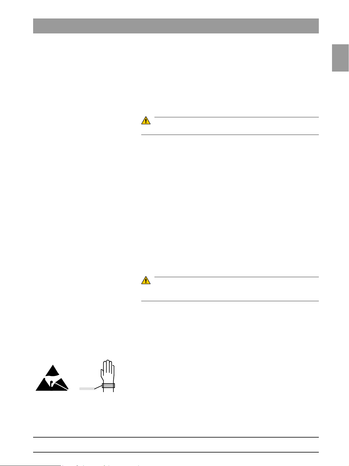
Please always wear an ESD wrist band to protect sensitive components on
printed circuit boards (ESD).
Always check the system and adjust it as required after replacing a board or
the X-ray tube assembly.
The part numbers for ordering spare parts can be found in the spare parts list,
Order No. 61 901 31. The diagrams contained in the spare parts list provide
a useful guide when replacing parts.
61 88 051 D 3352
D 3352.031.05.04.02 07.2008
1 – 5
Page 14
1.3 Demo mode – Operation without radiation release Tab 1
B
A
4.3.
1.
2.
S2
Board DX6
J6
1.3
Demo mode – Operation without radiation
release
1 – 6 D 3352.031.05.04.02 07.2008
61 88 051 D 3352
Page 15
1.3
Tab 1 1.3 Demo mode – Operation without radiation release
P1
______
6414.1
__ _
8
SYSTEMSOFTWARE
____
5.
123
(
123
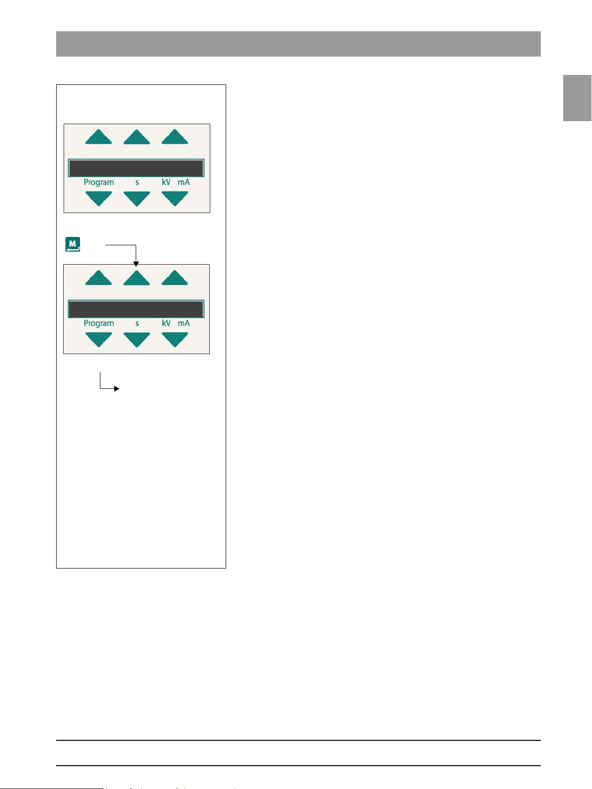
Scroll through the list
until the demo mode is
displayed
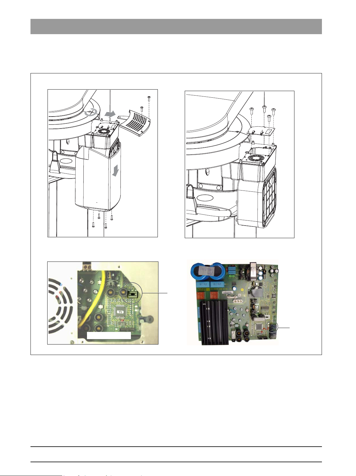
1.3.1 Switching the demo mode ON
When operated in demo mode, the unit must not release any radiation. For
this reason, you must take the following safety measures:
z Switch the unit OFF.
1. Remove the cover of the tube assembly.
2. Loosen screws A and remove cover plate B.
3. Set dip switch S2 (DX6) to position 2.
4. Remove cable L5 (X-RAY) from connector J6 (DX6).
Radiation release is now no longer possible.
5. Switch the unit ON and check the mode with the info menu.
Demo mode: ON means that: The demo mode is switched ON
(Radiation release is not possible)
Demo mode: OFF means: The demo mode is switched OFF
(Radiography, X-ray radiation are possible!)
z Switch the unit OFF again and reattach cover plate B and the tube assem-
bly covers by following the dismantling procedure in reverse order.
1.3.2 Switching the demo mode OFF
z Switch the unit OFF.
1. Remove the cover of the tube assembly.
1.3
bеЦдблЬ
2. Loosen screws A and remove cover plate B.
3. Set dip switch S2 (DX6) to position 1.
4. Replace cable L5 (X-RAY) on connector J6 (DX6).
Radiation release is now once again possible.
5. Switch the unit ON and check the mode with the info menu.
Demo mode: ON means that: The demo mode is switched ON
(Radiation release is not possible)
Demo mode: OFF means: The demo mode is switched OFF
(Radiography, X-ray radiation are possible!)
z Switch the unit OFF again and reattach cover plate B and the tube assem-
bly covers by following the dismantling procedure in reverse order.
61 88 051 D 3352
D 3352.031.05.04.02 07.2008
1 – 7
Page 16
1.4 Demo mode – Repacking and transport Tab 1
NOTE
i
1.
A
NOTE
i
If the unit is installed with a floor stand, its height increases by 30 mm. The bite block height value displayed on the Control Pad remains the same, however!
1.4
Demo mode – Repacking and transport
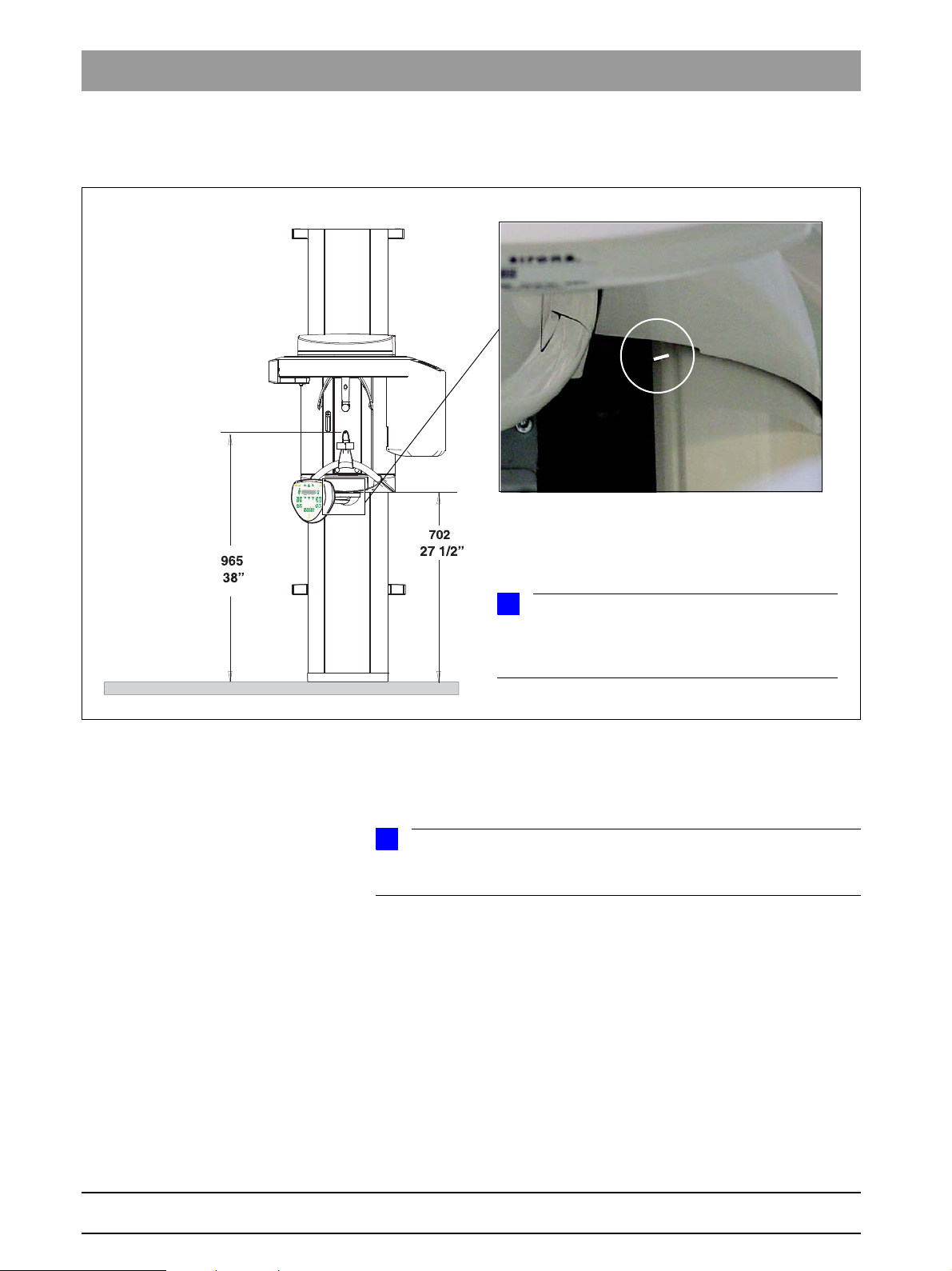
Panoramic X-ray unit z Switch the panoramic X-ray unit ON and move it to its packing height by
pressing the
– Bite block height = 965 mm (displayed as height on Control Pad
– Bottom edge of slide cover = 702 mm
The bottom edge of the slide cover must be at the same height as the markings A in the column.
Cephalometer z Start service routine S034, test step 6.
z Move the cephalometer to the packing position
(see page 5-81).
z For information on packing the units and on the packing condition, see the
relevant installation instructions.
1 – 8 D 3352.031.05.04.02 07.2008
UP/DOWN keys on the Control P.
61 88 051 D 3352
Page 17
1.5
Tab 1 1.5 List of software versions
NOTE
i
NOTE
i
CAUTION
1.5 List of software versions
Any software combinations other than those listed here are not allowed.
If the software version of any particular module does not match the overall
software version, the overall software version will be marked with an asterisk
on the info screen (e.g. 02.30*).
1.5
bеЦдблЬ
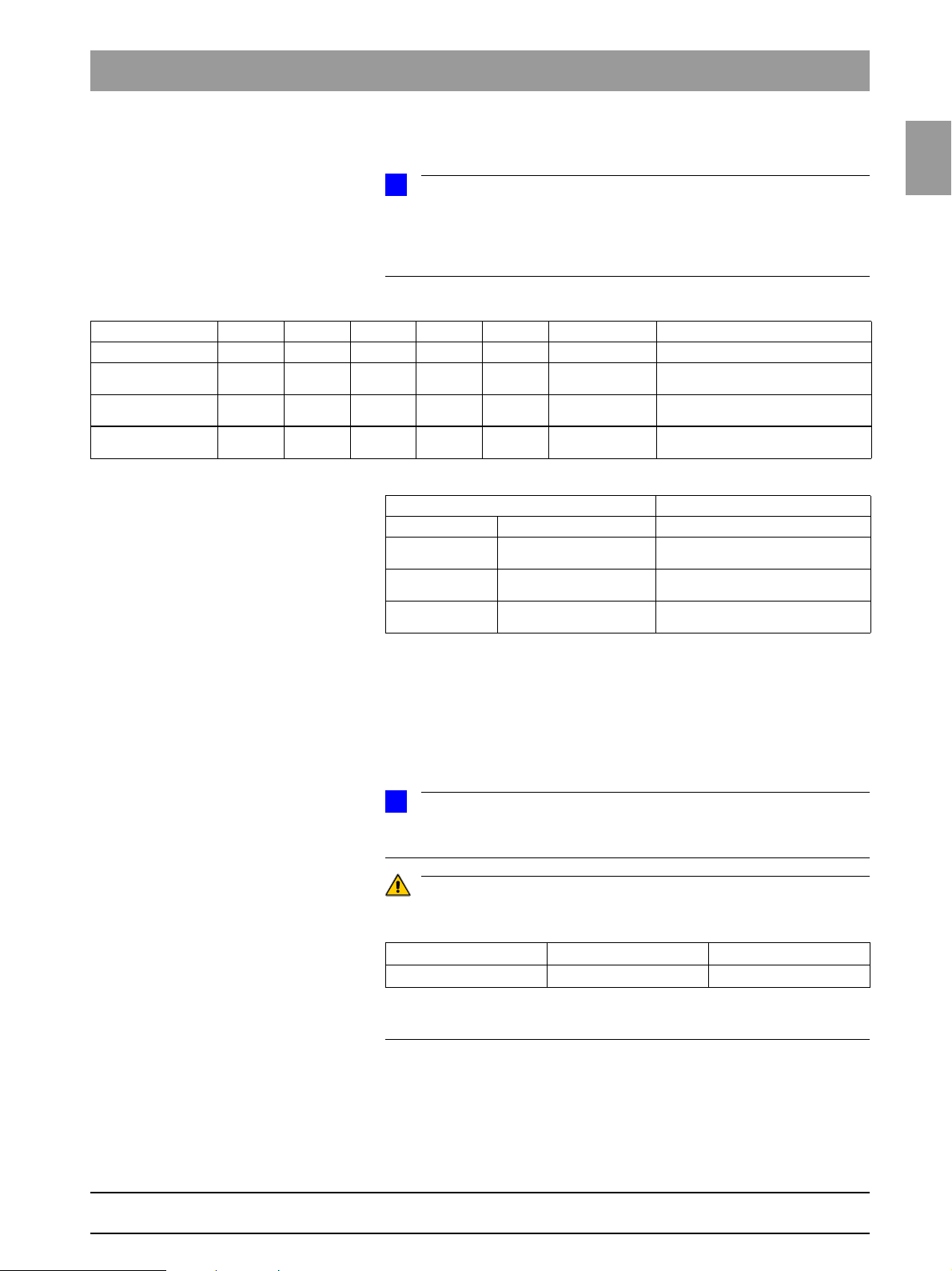
Panoramic unit Cephalometer
Board DX6 DX71 DX11 DX61 DX81 DX91
Overall software
V 02.30.00
Overall software
V 02.31.00
Overall software
V 02.32.00
02.60 02.33 02.42 02.34 02.33 02.43 CDR Software V4.3
02.60 02.33 02.42 02.34 02.33 02.44 CDR Software V4.3
02.60 02.33 02.43 02.35 02.33 02.44 CDR Software V4.3
Remote control
Board DX42
Overall software
V 02.30.00
Overall software
V 02.31.00
Overall software
V 02.32.00
02.31
02.31
02.31
1.6 Software update
1.6.1 Important information on the software update
Remarks
Remarks
61 88 051 D 3352
D 3352.031.05.04.02 07.2008
Read the information provided on the CDR PanElite Support CD. It contains the latest information on the software update.
Important for units with the following serial numbers or higher:
without Ceph with Ceph
PanElite 200000 220000
A downgrade to a software version < V02.32 cannot be performed on these
units.
1 – 9
Page 18
1.6 Software update Tab 1
NOTE
i
NOTE
i
2.
4. 5.
1.6.2 Performing a software update
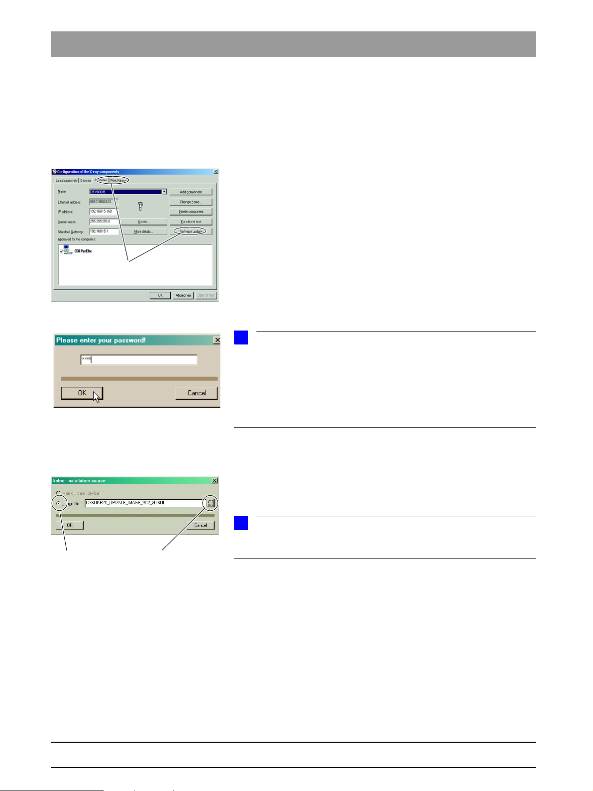
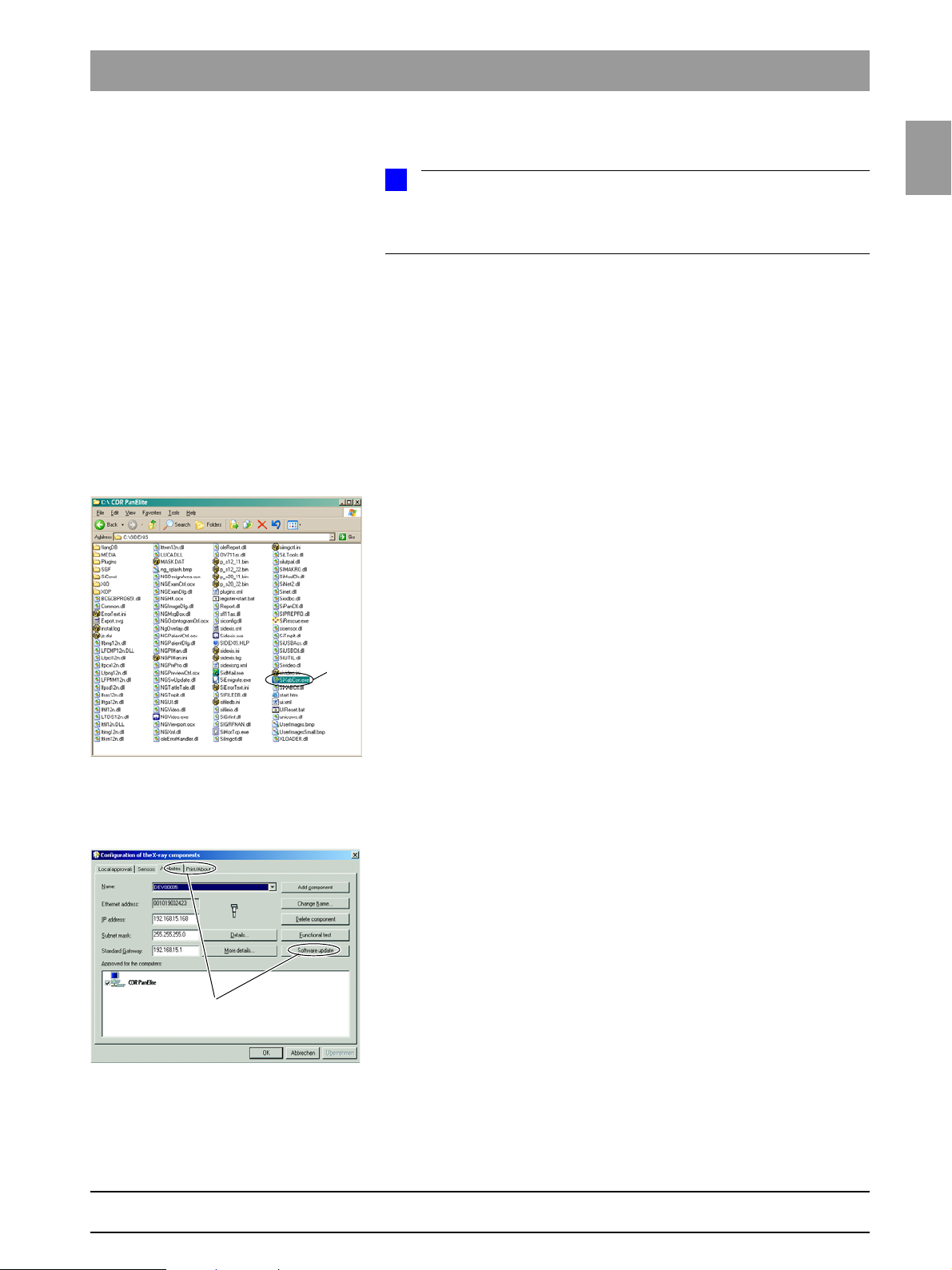
Opening SIXABCON.exe 1. Open the SIXABCON utility program in the CDR PanElite program folder.
Click on SIXABCON.exe.
to open the
Entering the password 3. Enter the service password.
SOFTWARE UPDATE menu 2. Open the SOFTWARE UPDATE menu.
Click the
The dialog box for entering the service password appears on the screen.
As a service password, enter the first 4 digits of the current system date in reverse order (e.g. on 05/24/1995, 5042 must be entered as the service
password.
If an incorrect service password or no password at all is then entered, the limited update menu for users will then be started. This includes only the possibility for an automatic update (see page 1-12).
ATTRIBUTES tab and then SOFTWARE UPDATE.
Selecting an installation source 4.
The dialog box for selecting the installation source opens.
IMAGE FILE is preset as the installation source for the software update.
5. Select the path and the desired update file and confirm your selection by
clicking
Click on
The update file can be found on the CDR PanElite Support CD. It is delivered
with each DX11 replacement board.
OPEN.
NAME UPDATE and OPEN.
1 – 10 D 3352.031.05.04.02 07.2008
61 88 051 D 3352
Page 19

1.6
Tab 1 1.6 Software update
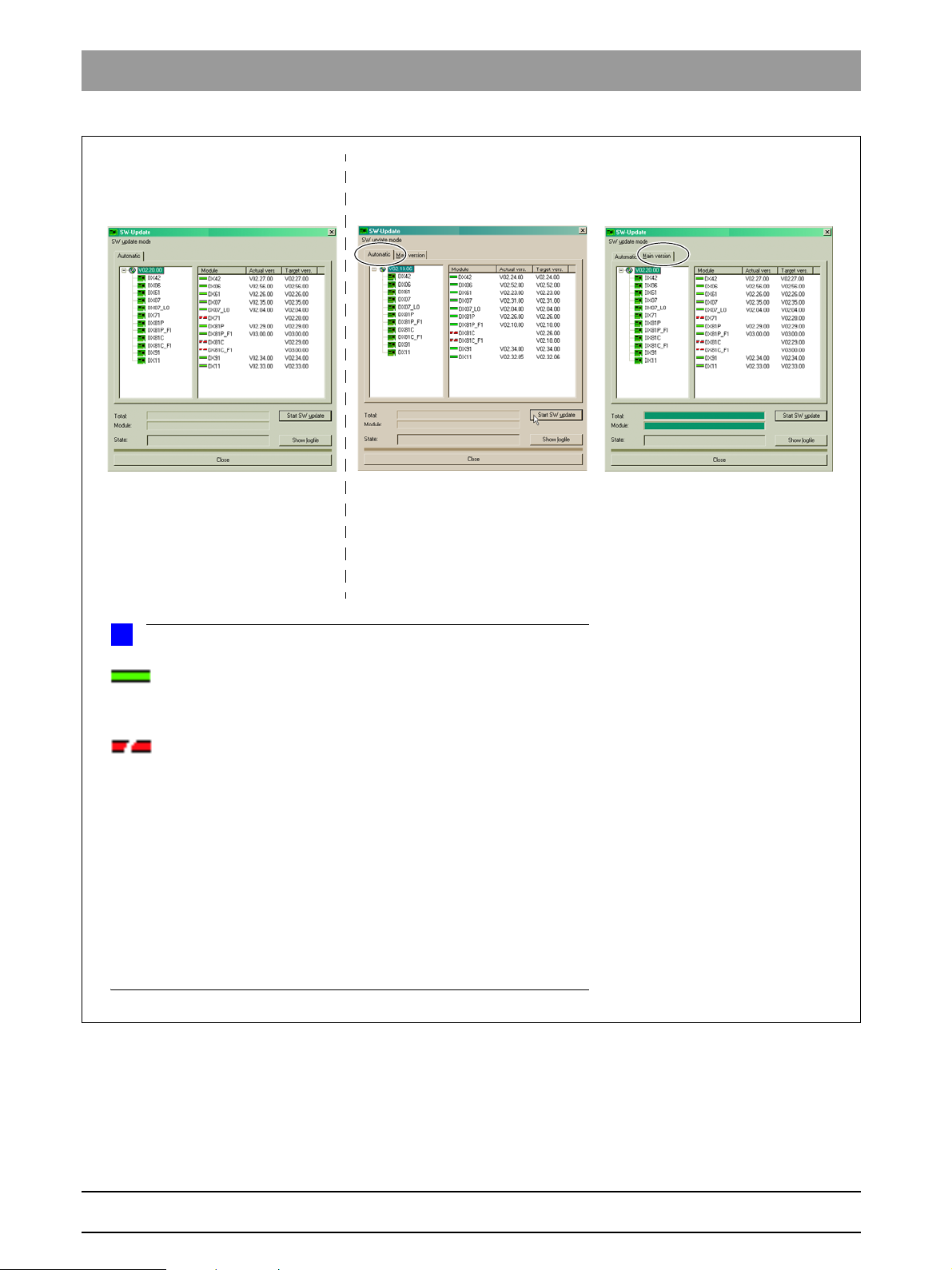
Selecting the update mode 6. Select the mode for the software update.
You can select two different update modes via the index tabs:
z Automatic
The software of all components is automatically updated a higher software version.
z Main version
The software can be upgraded or downgraded to the desired version.
This update mode is required e.g. if a replacement component delivered
out of stock has a newer status than the prevailing overall system status.
In this case, a main version update to the overall system status (displayed
on the info screen) must be performed for the corresponding component
with the appropriate update file (*.SUI). The module is then reprogrammed.
(For more information on the update mode, see the next page.)
1.6
bеЦдблЬ
61 88 051 D 3352
D 3352.031.05.04.02 07.2008
1 – 11
Page 20
1.6 Software update Tab 1
Automatic
A list of modules, their installed software version and the latest software
version offered by the update function is displayed in the right pane.
Main version
(E.g. if modules have a newer version status than the overall system
following module replacement.)
Automatic
(Accessible without password.)
NOTE
i
Modules which are connected and whose program status agrees
with that of the current main program version are marked by a continuous
green bar.
Modules which are not elements of the current system configuration
or, as a removable medium (e.g. sensors) are not connected, are marked by
a broken red bar.
If the actual status of the module could not be polled forthe update, the actual SW version will then be displayed as = V00:00.
If a module has a hardware incompatibility to the program status to be programmed or the software version on the module is newer than the one in the
update file, this will be indicated by a red triangle with an exclamation mark.
If the version of the selected update file is lower than the current software version of the unit, then there will be no display in the right window. The downgrade required in this case is possible only via the MAIN VERSION mode.
User domain
Service domain
1 – 12 D 3352.031.05.04.02 07.2008
7. Select the update mode and the update or component.
61 88 051 D 3352
Page 21
1.6
Tab 1 1.6 Software update
NOTE
i
NOTE
i
7.
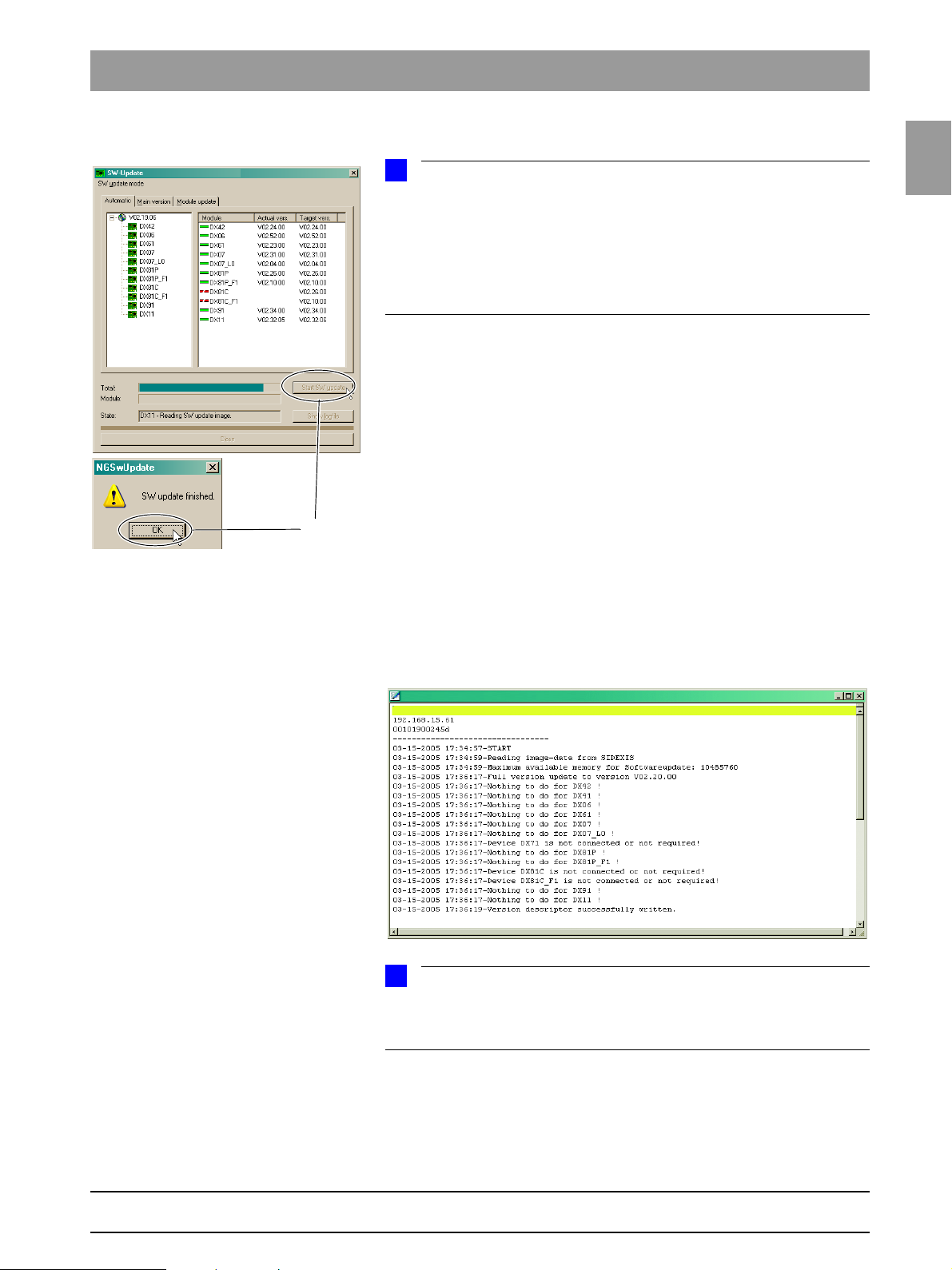
Starting the update 8. Start the update by clicking START UPDATE.
Before starting the software update, make sure that no unit movements are
active (especially any diaphragm movements)! Otherwise the system may become inoperable in rare cases.
1.6
All of the sensors located in the unit (Pan or Ce ph) must be ins erted i n the cor responding slots. Exposure readiness must be deselected in the CDR Service
program and the system must not be in the service mode already.
The update is started. A message box informs you when the update process is completed. Confirm the update with
Checking the log file 9. Check the log file to make sure that the update was completed success-
fully.
SHOW LOGFILE.
Click
OK.
bеЦдблЬ
61 88 051 D 3352
D 3352.031.05.04.02 07.2008
If messages such as Update of DXxx failed! appear there, please perform
the update again. Repeat this procedure as often as necessary until the
“failed” messages no longer appear.
1 – 13
Page 22
1.6 Software update Tab 1
CAUTION
NOTE
i
NOTE
i
SW Update Manager
10. Reboot the system.
It is always necessary to reboot the system after any software update.
Any errors with the consecutive numbers 01, 03, 04, 06 and/or 07 displayed
immediately following the software update may be ignored. If these messages
appear again after the unit is rebooted, perform troubleshooting according to
Section 2.4.
If anything conspicuous occurs in connection with system handling on completion of the software update, please repeat the software update as the first
measure. Also check whether the system software version is displayed without an asterisk (*) on the info screen.
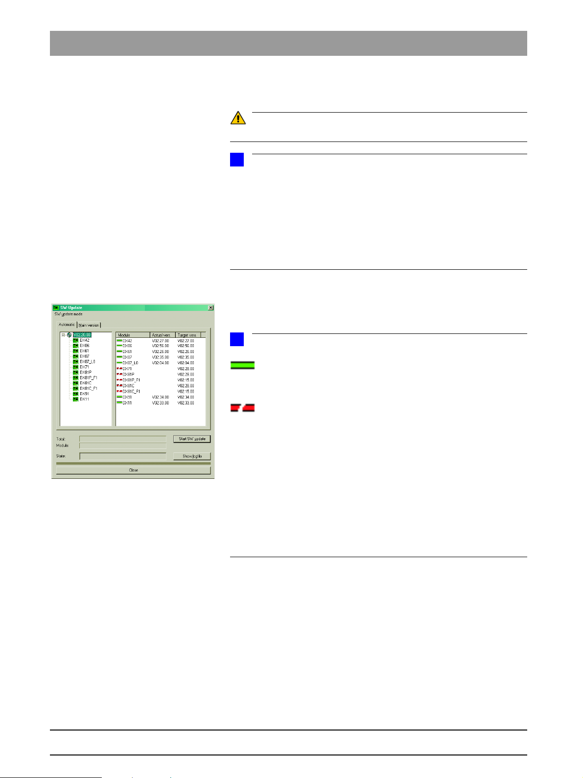
Checking the program versions 11. Check whether all modules contain the current program version via the
SW Update Manager or service routine S008.2 (see page 5-35).
Program version included.
Modules which are connected and whose program status agrees with
that of the current main program version are marked by a continuous green
bar.
Modules which are not elements of the current system configuration
or, as a removable medium (e.g. sensors) are not connected, are marked by a
broken red bar.
If the actual status of the module could not be polled forthe update, the actual
SW version will then be displayed as = V00:00.
If a module has a hardware incompatibility to the program status to be programmed or the software version on the module is newer than the one in the
update file, this will be indicated by a red triangle with an exclamation mark.
If the version of the selected update file is lower than the current software version of the unit, then there will be no display in the right window. The downgrade required in this case is possible only via the MAIN VERSION mode.
12. Open the "Extended Details“ via SIXABCON.
This generates an XML file (with the system parameters) which is filed under the network name of the system as XML file under the network name
of the unit in the PDATA/P2K_Config folder (see also page 1-15).
1 – 14 D 3352.031.05.04.02 07.2008
61 88 051 D 3352
Page 23
1.7
Tab 1 1.7 Selecting More details
NOTE
i
1.
2.
1.6.3 Perform a software update (if necessary)
If the sensors previously used are to be used in the future as well, plug them
into the slots on the panoramic unit and/or cephalometer before you begin the
update.
1.7
1. Switch the unit ON.
2. Perform the software update (automatic update) as described on page
1-9.
3. Switch the unit OFF.
Wait for approx. 1 minute. Then switch the unit ON again.
1.7 Selecting More details
Opening SIXABCON.exe 1. Open the SIXABCON utility program in the CDR PanElite program folder.
Click on SIXABCON.exe (see screen shot).
bеЦдблЬ
Opening the
EXTENDED DETAILS menu 2. Open the EXTENDED DETAILS menu.
61 88 051 D 3352
D 3352.031.05.04.02 07.2008
Click the
The current parameters are read from the PDATA/P2K_Config folder.
This process can take up to 30 seconds.
ATTRIBUTES tab and then EXTENDED DETAILS.
1 – 15
Page 24
1.7 Selecting More details Tab 1
NOTE
i
-------------------------------------------------------------------
--------------------- Changed Systemparameter ---------------------
-------------------------------------------------------------------------The following systemparameters have been changed compared to the factory
settings.
After replacing an DX11-PCB, the listed values must be reconfigured.
--- Changed System Configuration Settings --Setting of system version (configured in S17.2)
actual value: 0x0043
Setting of remote control activation (configured in S17.6)
actual value: active (01)
Setting of image format (configured in S17.11)
actual value: enabled (01)
Settings of CEPH-adjustment (Stored by the adjustment-routines)
actual value: DAlpha = 2734 | DX = 0 | DY = 33930
Settings of CEPH-adjustment QuickShot (Stored by the adjustment-routines)
actual value: DAlpha = 2734 | DX = 0 | DY = 33930
Setting of display usage count threshold (configured in S17.23)
actual value: 550
Settings of network configuration
actual value: IP: 192.168.15.176 | Subnet: 255.255.255.0 | Gateway: 192.168.15.1
--- Changed User Preference Settings --Setting of default patientsymbol CEPH (configured in 'select starting settings')
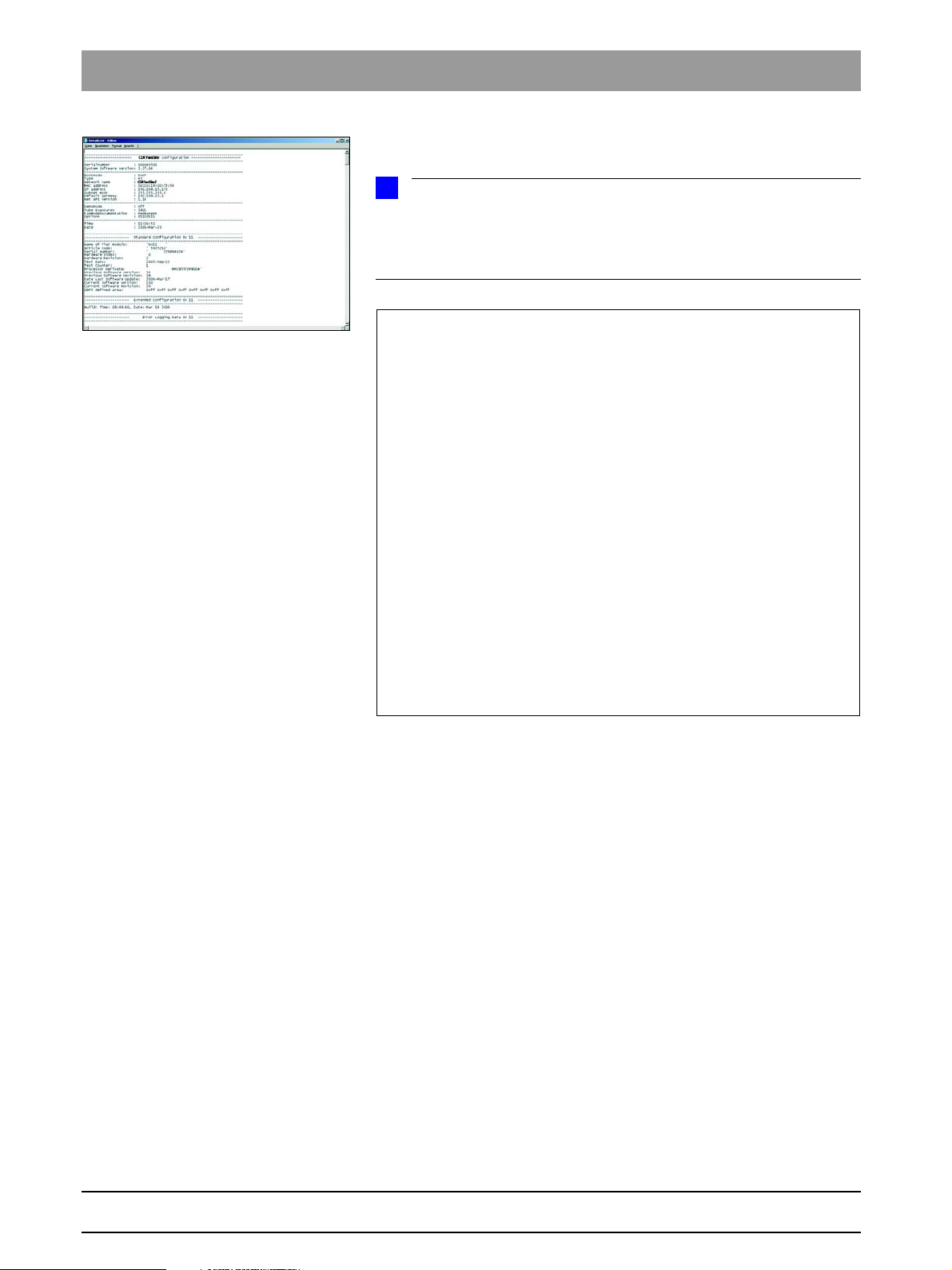
After the parameters are read, an editor displaying the XML file is opened
automatically.
You can scroll down further in the file using the scroll bar. The "Changed
system parameters", i.e. the system parameters that were modified in relation
to the factory setting, are displayed there. This is especially interesting after a
module change. The parameter settings can thus be easily traced.
1 – 16 D 3352.031.05.04.02 07.2008
61 88 051 D 3352
Page 25
1.8
Tab 1 1.8 The most import ant modules and components
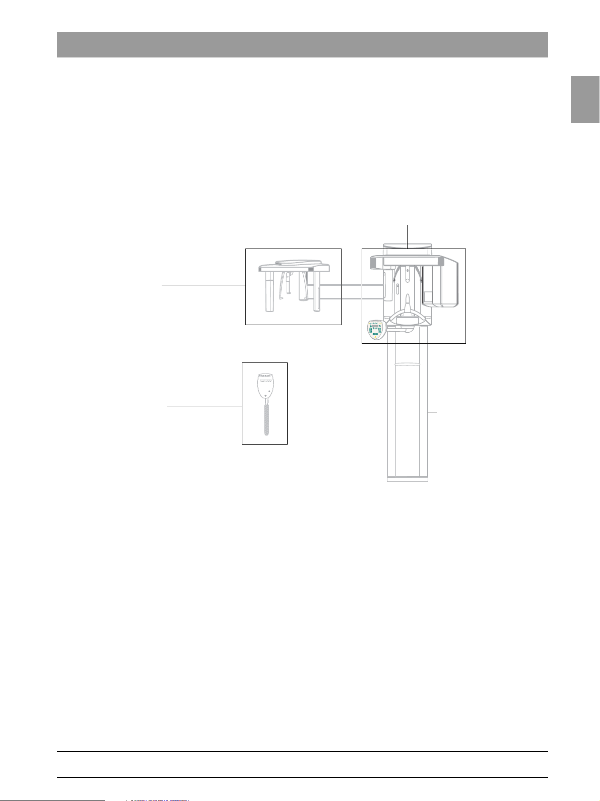
Cephalometer,
(see section 1.8.3)
Remote control
(see section 1.8.4)
Slide
(see section 1.8.1)
Stand
(see section 1.8.2)
1.8 The most important modules and components
The X-ray system comprises the following main modules:
z Slide with rotary unit
z Stand
z Cephalometer
z Remote control (optional)
1.8
bеЦдблЬ
61 88 051 D 3352
D 3352.031.05.04.02 07.2008
1 – 17
Page 26
1.8 The most important modules and components Tab 1
DX11
DX1
DX5*
DX6*
DX61
DX81P*, DX85P*
LS*
M1*, M2*
MU
LS
LS
M AK1, M AK2
*) not available as individual spare part
(see spare parts list)
DX71
Control Pad
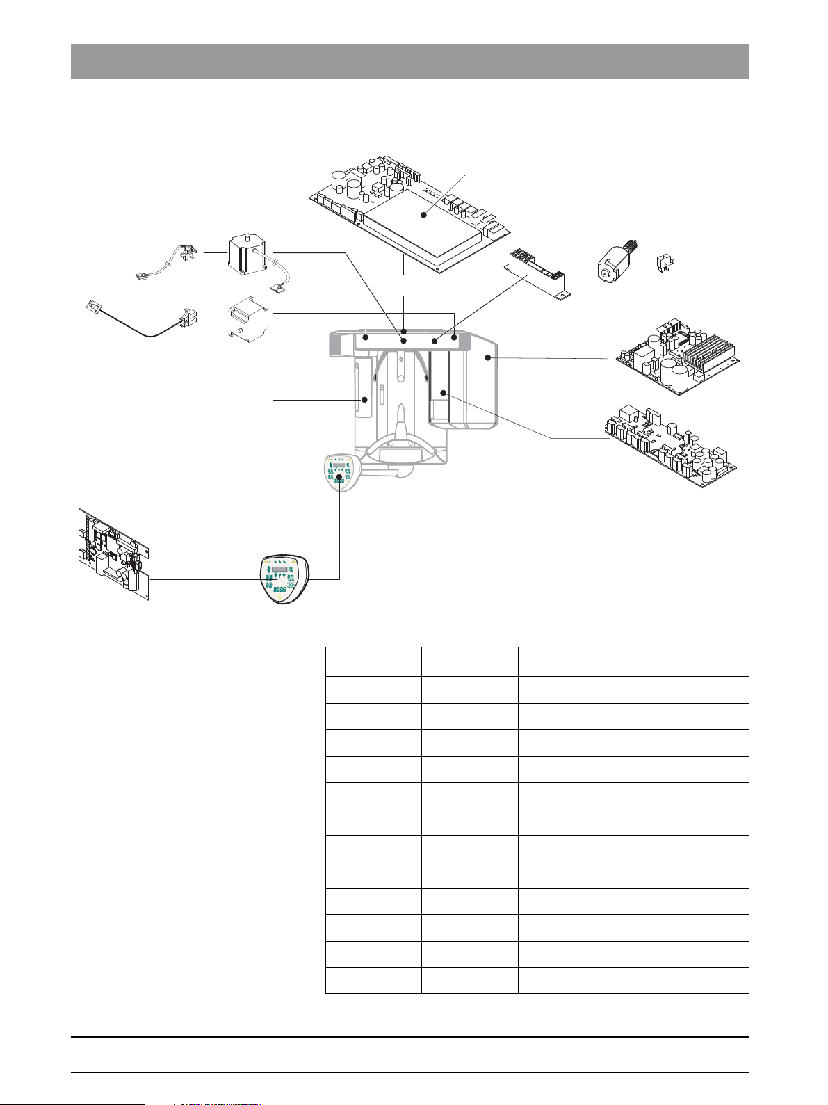
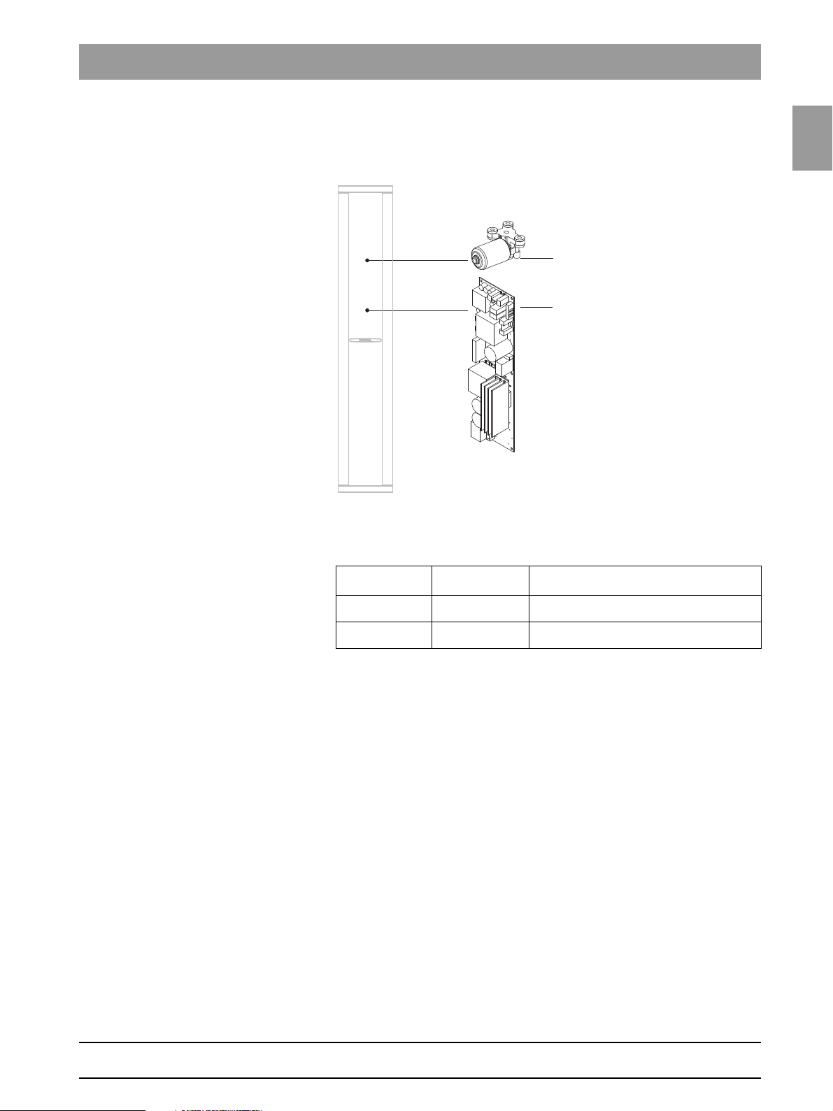
1.8.1 Slide
Component Designation Function
Boards DX1 Open-loop/automatic control in general
DX11 Controller board
DX5* Headrest adapter
Motors M1*, M2* Linear movement of headrest
Light barriers LS Position check
DX6* Open-loop/automatic control for tube assembly
DX71 LED display on Control Pad
DX61 Diaphragm control
DX81P Digital sensor
DX85P* Digital sensor power supply
M U Rotary movement of rotating element
AK1, AK2 Linear movement of rotating element
61 88 051 D 3352
1 – 18 D 3352.031.05.04.02 07.2008
Page 27
1.8
Tab 1 1.8 The most import ant modules and components
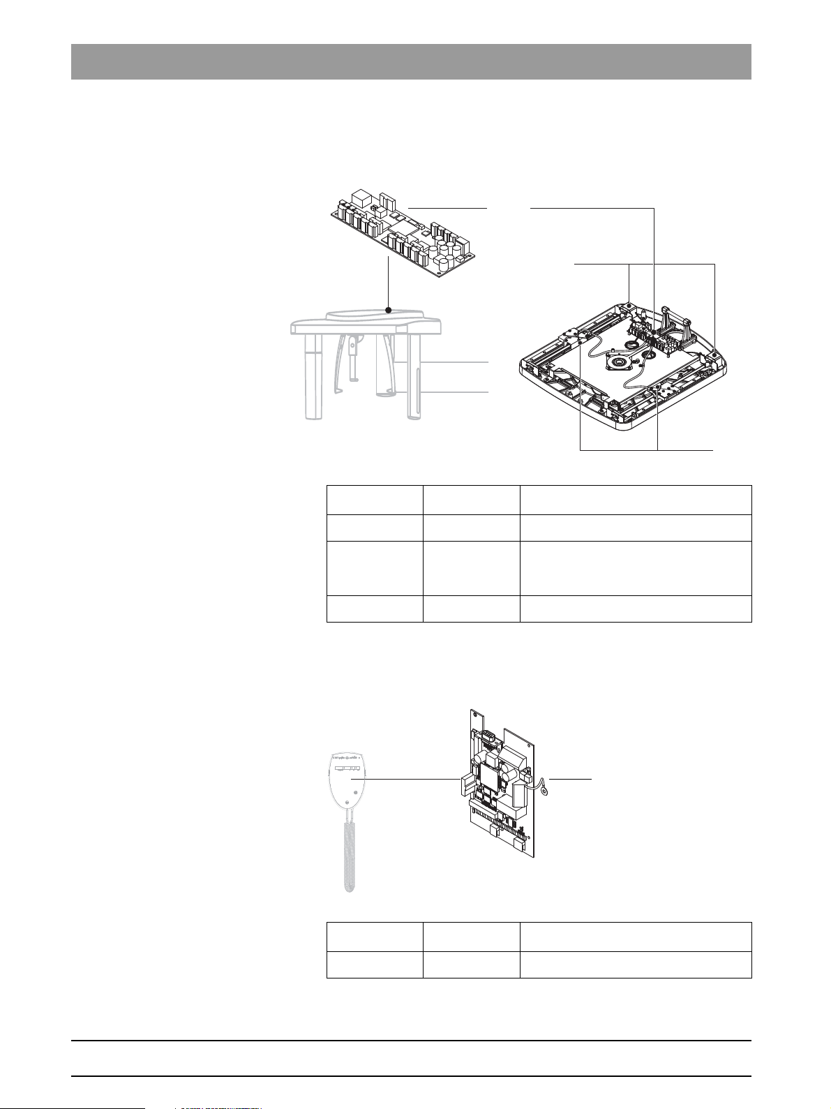
DX32
M HA
1.8.2 Stand
1.8
bеЦдблЬ
Component Designation Function
Boards DX32 Power supply board
Motors M HA Linear movement of height adjustment
61 88 051 D 3352
D 3352.031.05.04.02 07.2008
1 – 19
Page 28
1.8 The most important modules and components Tab 1
DX91
M S
LS
DX42
1.8.3 Cephalometer
Component Designation Function
Boards DX91 Cephalometer control
Motors M S Stepping motors:
linear movement of secondary diaphragm
and sensor
Light barriers LS Position check
1.8.4 Remote control
Component Designation Function
Boards DX42 Display board for remote control
1 – 20 D 3352.031.05.04.02 07.2008
61 88 051 D 3352
Page 29
1.9
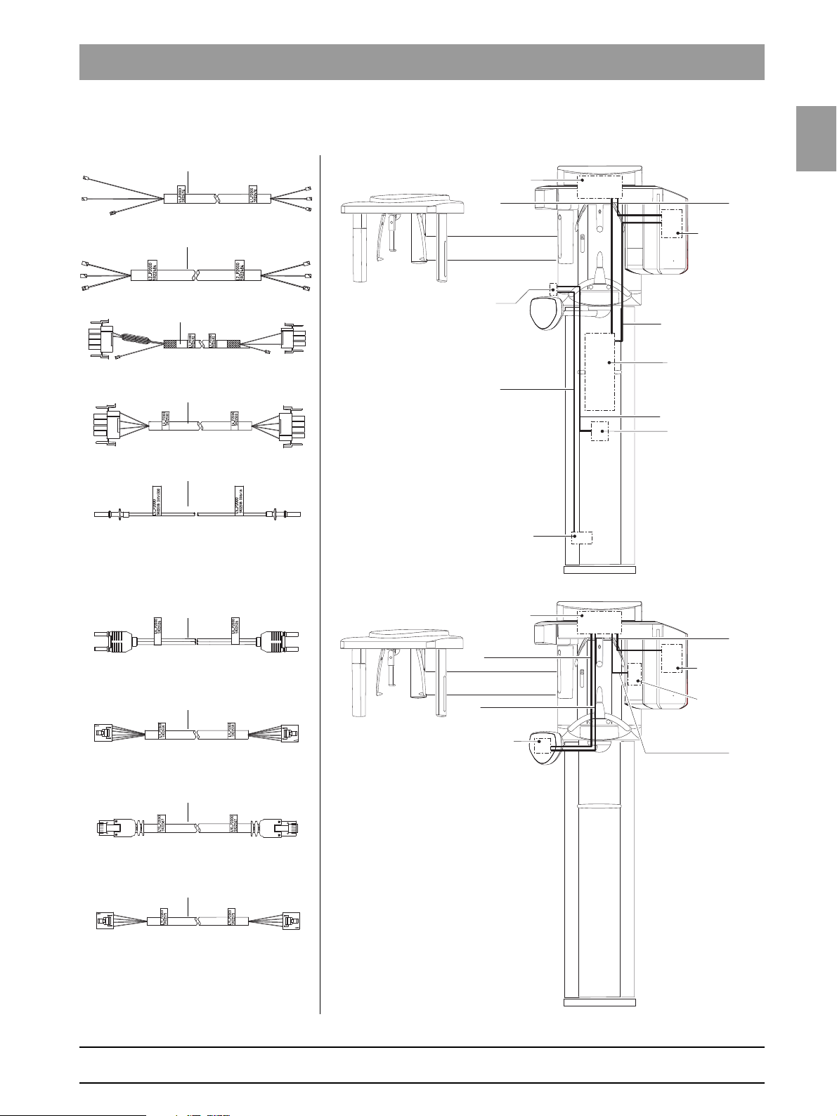
Tab 1 1.9 Cabling overview
TERMINAL
POWER SWITCH / S1
2
PC-BOARD DX32
PC-BOARD DX6
1
3
PC-BOARD DX1
4
POW
ER FILTER
5
DX32 / X2
DX6 / X3
DX32 / X1
DX1 / X100
DX1 / J302
DX6 / J6
1
2
3
4
5
DX1 / J306 – J302
DX6 / J2 – J3
DX1 / X104
DX7 / X102
DX1 / X302
DX7 / X103
DX1 / X102
DX61 / X501
6
9
10
11
PC-BOARD DX6
PC-BOARD DX1
6
PC-BOARDDX71
9
10
PC-BOARD DX61
11
1.9 Cabling overview
1.9
bеЦдблЬ
61 88 051 D 3352
D 3352.031.05.04.02 07.2008
1 – 21
Page 30
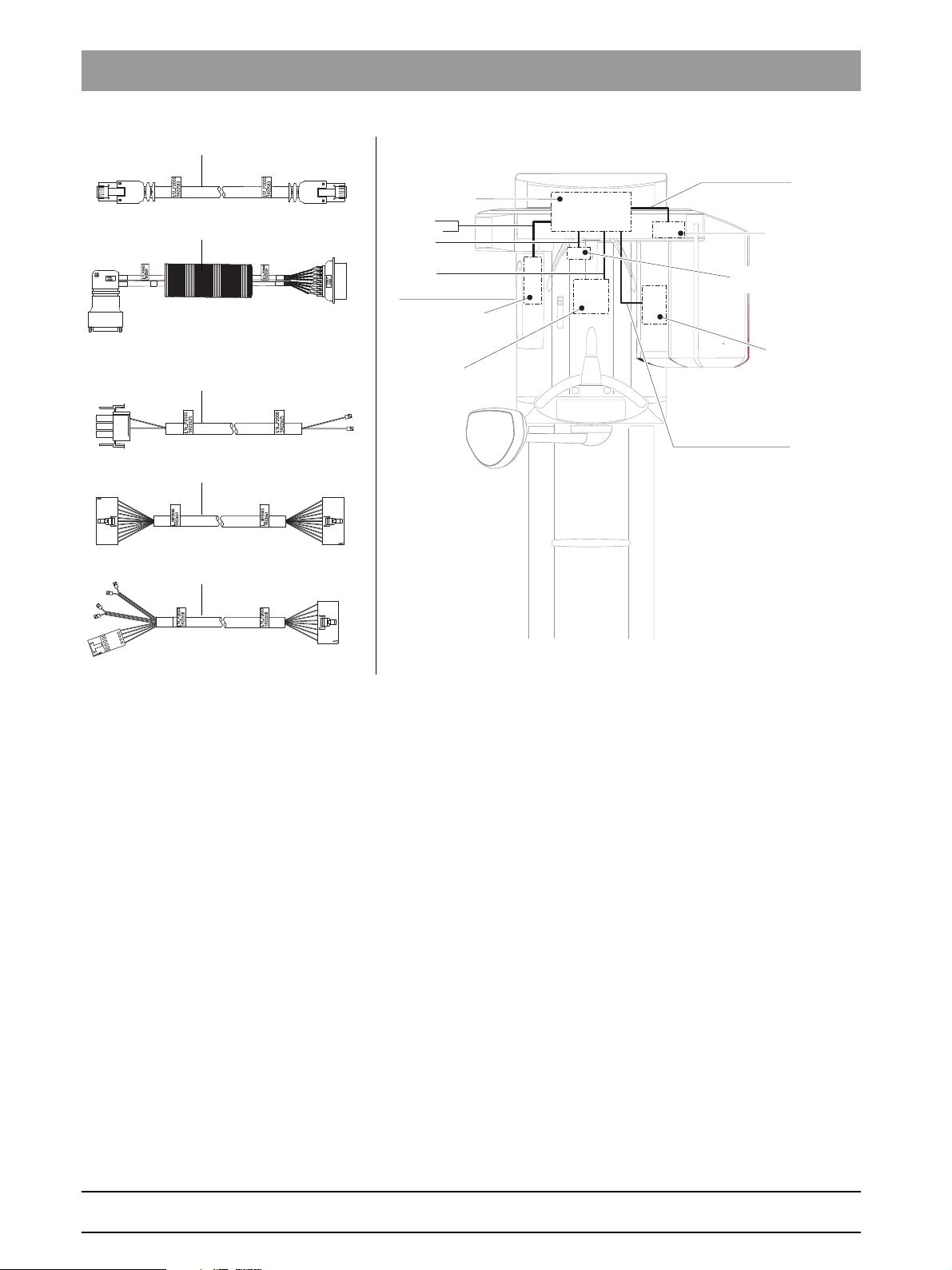
1.9 Cabling overview Tab 1
DX1 / X306
DX61 / X101
DX1 / X500
DX81 / X100
DX1 / X404
DX5 / X1
DX1 / X610
DX1 / X403
12
16
13/13.1
18
19
PC-BOARD DX1
PC-BOARD DX61
12
HV-MOTOR / FILTER
16
PC-BOARD DX5
18
PC-BOARD DX81
19
13
13.1
LS-SENSOR , LIMIT SWITCH
ABOVE AND DO
WN
61 88 051 D 3352
1 – 22 D 3352.031.05.04.02 07.2008
Page 31

1.9
Tab 1 1.9 Cabling overview
DX61 / X203
TSA Motor
DX61 / X91
DX5
LASER
LS
AMP
LS
L24_XG
6090760
L24_XG
6090760
DX91/
X407
DX91/
X302
AMP
DX91/X302
DX91/X407
LS Sensor
Laser
DX81 / X100
DX1 / X503
DX1 / J901
21
23
24
35
38
7
20
31
PC-BOARD DX61
21
35
PC-BOARD DX91
LASER MODULE
PC-BOARD DX5
23
MOTOR
POTENTIOMETER
31
PC-BOARD DX81
PC-BOARD DX1
38
21
24
20
117
PC-BOARD DX42
MEDIA CON
V
ERTER
25
26
PC-BOARD DX1
7
108
Media Konverter
25/26
L108_XG
6094705
DX1/
X303
L117/
X103
L108_XG
6094705
DX1 / X303
L117 / X103
108
L117_XG
6094697
L117_XG
6094697
DX42 / X100
L108 / X103
117
1.9
bеЦдблЬ
61 88 051 D 3352
D 3352.031.05.04.02 07.2008
1 – 23
Page 32

1.9 Cabling overview Tab 1
DX91 / X6
SHR INK HOSE
DX91 / X101
DX1 / X103
DX1 / X309
CO
VER, BLUE
CO
VER, BLUE
36
37
39
40
37
PC-BOARD DX91
PC-BOARD DX1
40
36
39
61 88 051 D 3352
1 – 24 D 3352.031.05.04.02 07.2008
Page 33

1.10
Tab 1 1.10 Illustrations of boards
DX1
DX11
X500
X307X503
X303
X104
X403
X611
X607
X306X302
J307
J306
J302
X402
X1000
X102
X103
X404
X804
X802
X803
X100
X811
X812
X813
X610
X309
J309 not used
X3
X4
X6 X1 X2
X5X7
1.10 Illustrations of boards
Boards DX1 / DX11
1.10.1 Boards in the slide
1.10
bеЦдблЬ
Board DX5
61 88 051 D 3352
D 3352.031.05.04.02 07.2008
1 – 25
Page 34

1.10 Illustrations of boards Tab 1
X2X1 X306X305
J2
J3
J6
S2
X3
F201
X501
X101
X203
X202
X406 X405
X402
X401
X400
X304
X303
X302
X301 X300
X200X201
TSA ports
Board DX6 (not available as spare part)
Board DX61
61 88 051 D 3352
1 – 26 D 3352.031.05.04.02 07.2008
Page 35

1.10
Tab 1 1.10 Illustrations of boards
NOTE
i
X104
X203
X202
X106
X103 X102
Board DX71
1.10
bеЦдблЬ
Board DX71 is shown here only for enhanced clarity. The Control Pad may be
replaced only as a complete unit!
61 88 051 D 3352
D 3352.031.05.04.02 07.2008
1 – 27
Page 36

1.10 Illustrations of boards Tab 1
NOTE
i
CAUTION
DX81
DX85
Boards DX81P / DX85P (not available as repair parts)
Boards DX81 and DX85 are shown here only for enhanced clarity.
Do not open the sensor! The sensor may be replaced only as a complete
unit!
61 88 051 D 3352
1 – 28 D 3352.031.05.04.02 07.2008
Page 37

1.10
Tab 1 1.10 Illustrations of boards
X100
F100X1
F101 F102
X2
X501
X101
X202
X304
X302
X201
X407
X306X307X308
1.10.2 Boards in the stand
Board DX32
Board DX91
1.10
bеЦдблЬ
1.10.3 Boards in the cephalometer
61 88 051 D 3352
D 3352.031.05.04.02 07.2008
1 – 29
Page 38

1.10 Illustrations of boards Tab 1
X200
X201
X107
X101
X108 X105 Jumper X109 und X110
V100
V103
V101
1.10.4 Boards in the remote control
Board DX42
61 88 051 D 3352
1 – 30 D 3352.031.05.04.02 07.2008
Page 39

1.11
Tab 1 1.1 1 Removing the covers
13
12
6
7
1
2
8
9
3
4
11
10
5
14
1. Profile cover
2. Intermediate piece
3. Arm cover, top
4. Slide cover, top rear
5. Slide cover, bottom rear
6. Support cover, top
7. Support cover, bottom
8. Tube assembly cover, front
9. Tube assembly cover, rear
10. Slide cover, center rear
11. Sensor holder cover
12. Slide cover, front complete
13. Ring cover
14. Cephalometer cover
1.11 Removing the covers
1.11
bеЦдблЬ
61 88 051 D 3352
D 3352.031.05.04.02 07.2008
1 – 31
Page 40

1.11 Removing the covers Tab 1
61 88 051 D 3352
1 – 32 D 3352.031.05.04.02 07.2008
Page 41

CDR PanElite
2 Messages
Page 42

Tab 2
Contents
2.1 Help messages .......................................................2 – 3
2.2 System messages...................................................2 – 5
2.3 Error messages.......................................................2 – 5
2.3.1 Ex yy zz................................................................ 2 – 6
2.3.2 Ex yy zz................................................................ 2 – 7
2.3.3 Ex yy zz ................................................................ 2 – 7
2.3.4 General handling of error messages .................... 2 – 7
2.4 List of error messages.............................................2 – 8
2.5 List of available service routines ...........................2 – 52
61 88 051 D 3352
2 – 2 D 3352.031.05.04.02 07.2008
Page 43

Tab 2 2.1 Help messages
2 Messages
The different message texts are displayed on the Control Pad display and on
the display of the remote control.
bеЦдблЬ
There are 3 groups of message texts:
z Help messages (Hx xx)
– Help messages are caused by operator errors
– The user must take action
z Error messages (Ex yy zz)
– Error messages indicate system faults
– The user must take action to eliminate the fault(s)
z System messages (Sxxx)
– System messages inform the user about the current operating
status of the system
– The user is not required to take action
2.1 Help messages
Help messages are displayed as help codes (Hxxx) on the display of the Control Pad and on the remote control display (if available). The codes tell you
how to operate the system if radiation release is not possible due to a previous operator error.
2.1
61 88 051 D 3352
D 3352.031.05.04.02 07.2008
2 – 3
Page 44

2.1 Help messages Tab 2
NOTE
i
NOTE
i
The following list provides you with an overview of all help codes, their meaning and the action required to eliminate the corresponding problems:
Help code Description Actions required
H3 01
H3 10
H3 20
H3 21
H4 01
The rotating element on the panoramic unit is
not located in its starting position.
The system is performing an action.
The exposure parameters have not been
acknowledged yet.
The X-ray room door contact is not detected.
The sensor on the panoramic unit is not properly
plugged in or is missing.
z Press the R key:
Panoramic unit moves to starting position.
z Wait until the system is ready.
z Press the R key:
Exposure data are confirmed.
z Close the door or check door contact.
z Plug sensor into PAN slot.
If this message does not disappear after the
sensor is plugged in, this indicates a system error. Perform error diagnosis according to
Section 3.4.
H4 02
H4 03
H4 04
H4 06
H4 10
The sensor on the cephalometer is not properly
plugged in or is missing.
CDR Software ore the CDR PanElite Service
Program is not ready for exposure.
The sensor does not match the selected
exposure type.
The cephalometer is not located in its starting
position.
The sensor is being polled.
z Plug sensor into Ceph slot.
If this message does not disappear after the
sensor is plugged in, this indicates a system error. Perform error diagnosis according to
Section 3.4.
z Make CDR Software or the CDR PanElite
Service Program ready for exposure.
z Plug in the ceph sensor.
z Press the R key:
Cephalometer moves to starting position.
z Wait until the message disappears.
61 88 051 D 3352
2 – 4 D 3352.031.05.04.02 07.2008
Page 45

Tab 2 2.2 System messages
NOTE
i
CAUTION
Ex yy zz
Error type
“Troubleshooting” classification for the user
Location
Module, subsystem or
logical function unit
Consecutive number
with identification
of the error
Help code Description Actions required
H4 20
The image could not be transferred to CDR
PanElite Software.
Do not switch the system off until the help
message has disappeared.
z Retrieve the exposure with CDR PanElite
Rescue (see CDR PanElite Operating
Instructions).
bеЦдблЬ
The above measures clear those help messages that result from operator
errors. If it is not possible to clear the help message by taking the above measures, another type of error is the cause. To identify the error, proceed as described in section 2.4 .
2.2 System messages
System code Description Actions required
S100
S110
CDR PanElite is started.
Exposure cannot be performed.
z Wait, no action required.
z Quit readiness for exposure,
switch unit OFF, wait for 30 sec., switch unit
back ON and observe error messages
displayed after switch-on.
z Repeat procedure if necessary.
2.3 Error messages
2.2
Error code: Ex yy zz The error messages are encoded according to the following pattern:
61 88 051 D 3352
D 3352.031.05.04.02 07.2008
Error messages are displayed as error codes (Ex yy zz) on the display of the
Control Pad or on the remote control display (if available).
The codes provide you with error type, error location and troubleshooting
information.
The error messages are sorted by modules in the table on page 2-6.
2 – 5
Page 46

2.3 Error messages Tab 2
2.3.1 Ex yy zz
Identifier x is supposed to help you quickly reach a decision on how to proceed with this error.
x Description Error group Actions required
System warning;
1
system message
Errors caused by
2
system overload
The system detects
3
that a key was pressed
during power-on
Malfunction or
4
mechanical obstruction
of unit movements
Malfunction during the
5
exposure or during
exposure preparation
6
Error during system
self-test
7
Unrecoverable
system error
This error group includes all errors that
indicate still acceptable tolerance variations,
or messages about states which do not
directly affect system operation.
This error group includes states that indicate
e.g. temporary overtemperatures or the like.
The cause of the error disappears
automatically after a certain waiting time.
This error group includes all errors that
indicate invalid signal states of keys and
safety signals during power-on.
This error group includes all errors that
indicate problems with the motor-controlled
movements on the outside of the unit.
This error group includes all errors resulting
from a certain system action triggered by the
user which could not be performed because
a required (internal) partial function
(software or hardware) is not ready or fails.
This error group includes all errors which
may occur spontaneously and without any
related operator action. They may be caused
by system self-tests.
This error group includes all errors which
may occur spontaneously and without any
related operator action. They may be caused
by system self-tests. In this case it is
absolutely sure that continued system
operation is not possible.
z Acknowledge the error message to
continue system operation. If the error
occurs repeatedly, switch the system
OFF and back ON.
If the error occurs again: Identify the error
by proceeding as described in
section 2.4.
z Acknowledge the error message.
z Repeat the procedure step after a certain
waiting time.
– If the error message reappears, pro-
long the waiting time.
– If the error state persists: Identify the
error by proceeding as described in
section 2.4.
z Switch unit OFF and ON again.
If the error occurs again, identify the error
by proceeding as described in
section 2.4.
z Acknowledge the error message and
make sure that the movements of the unit
are not obstructed.
z Repeat the last procedure step or
exposure. If the error reoccurs without
any identifiable cause: Identify the error
by proceeding as described in
section 2.4.
z Acknowledge the error message.
z Repeat the last procedure step or
exposure. If the error occurs again:
Identify the error by proceeding as
described in section 2.4.
z Acknowledge the error message.
z Identify the error by proceeding as
described in section 2.4.
Note:
The unit can no longer be operated.
z Identify the error by proceeding as
described in section 2.4.
61 88 051 D 3352
2 – 6 D 3352.031.05.04.02 07.2008
Page 47

Tab 2 2.3 Error messages
2.3.2 Ex yy zz
Identifier yy defines the location or logical function unit where the error has
occurred.
yy Location/Function unit Board
06
61
71
10
11
12
13
14
15
42
81
91
Tube assembly DX6
Diaphragm control DX61
User interface on the Control Pad DX71
System hardware DX11/DX1
System software DX11/DX1
CAN bus DX11/DX1
Stand peripherals DX11/DX1
Digital extension DX11/DX1
Configuration/update (wrong software, wrong module configuration, etc...) DX11/DX1
Remote control DX42
Sensor (Pan slot: zz = 1-23; Ceph slot: zz = 51-73) DX81
Cephalometer DX91
bеЦдблЬ
2.3
The location may be a DX module number standing for an entire HW function
unit, or a logical SW function unit on board DX11 (central control).
2.3.3 Ex yy zz
The identifier zz represents a consecutive number with the error identification.
2.3.4 General handling of error messages
Error messages always must be acknowledged with the R key.
If failure-free operation is possible after the error is acknowledged, then no
further action is necessary.
If error messages reoccur or occur frequently, identify the error as described
in section 2.4 and take appropriate action to eliminate the corresponding error
or fault.
In some cases, it may make sense to obtain more information on the history
and frequency of errors via the error logging memory (S007) and
SIXABCON‡PROPERTIES‡EXTENDED DETAILS (see section 1.7 on page 1-
15) (see also section 3.1).
61 88 051 D 3352
D 3352.031.05.04.02 07.2008
2 – 7
Page 48

2.4 List of error messages Tab 2
NOTE
i
2.4
In the following table, the error codes are sorted by the location or function unit
where the error has occurred. For enhanced clarity, the corresponding ID in
the error code is printed in bold type.
Location 06: Tube assembly/Board DX6
List of error messages
Error code Description Actions required see page
E6 06 01
E6 06 02
E6 06 03
E6 06 04
E6 06 05
General error during module
initialization
Invalid system data or uninitialized
module storage data
Invalid response of control data, CAN
bus error
Note:
This error may also occur in
connection with other causal error
messages! Please also observe the
causal error message! It appears only
after you acknowledge the first error
message.
Data transfer error or dialog error to
module (master side)
Data transfer error or dialog error to
bootloader of module
Note:
Occurs only in connection with
software update
z Please contact dealer tech support to see if a
software update is necessary.
z If the error occurs frequently,
replace the X-ray tube assembly.
z Run service routine S005.2
z Please contact dealer tech support to see if a
software update is necessary.
z Check CAN bus.
z Please contact dealer tech support to see if a
software update is necessary.
z Check CAN bus.
z Please contact dealer tech support to see if a
software update is necessary.
z Repeat software update.
z Check CAN bus.
z If the error occurs repeatedly or the module is
no longer addressable, replace the tube
assembly.
1-9
6-36
6-21
1-9
3-6
1-9
3-6
1-9
1-9
3-6
6-36
61 88 051 D 3352
2 – 8 D 3352.031.05.04.02 07.2008
Page 49

Tab 2 2.4 List of error messages
Error code Description Actions required see page
E6 06 06
E6 06 07
E6 06 08
E7 06 10
Module failed in TTP*
(detected on master side)
Note:
This error may also occur in
connection with other causal error
messages. Please also observe the
causal error message! It appears only
after you acknowledge the first error
message.
TTP* timeout error
(detected on slave side)
Note:
The module was temporarily not
addressed by the master:
- Undervoltage on the master side
- Procedure error in the software
- Master (DX11) receives no
return response from the module
Note:
This error may also occur in
connection with other causal error
messages! Please also observe the
causal error message! It appears only
after you acknowledge the first error
message.
General fault detected locally on
module (slave side). CAN controller
being reinitialized
Module is stuck in bootloader stage
z Check CAN bus.
z Please contact dealer tech support to see if a
software update is necessary.
z If the error occurs repeatedly or the module is
no longer addressable, replace the tube
assembly
z Check CAN bus.
z Check power supply of board DX11; measuring
point 3.3 V on board DX1 (see wiring diagrams).
– If 3.3 V are present, replace board DX11
– If 3.3 V are not present, replace board DX11
– Check cable L6,
replace if necessary
– Check tube assembly (DX6)
replace if necessary
z Check CAN bus.
z Check software versions via info screen or
service routine S008.2,
perform a software update if necessary.
z Please contact dealer tech support to see if a
software update is necessary.
z Replace the X-ray tube assembly.
z Check board DX6 (note LED states).
If the board remains in the bootloader stage...
z Repeat software update.
z Replace the X-ray tube assembly.
3-6
1-9
6-36
3-6
6-55
6-55
3-17
6-65
6-36
3-6
5-35
1-9
1-9
6-36
3-12
1-9
6-36
bеЦдблЬ
2.4
61 88 051 D 3352
D 3352.031.05.04.02 07.2008
2 – 9
Page 50

2.4 List of error messages Tab 2
Error code Description Actions required see page
E7 06 12
E6 06 13
E2 06 20
E6 06 21
E6 06 22
E3 06 23
E5 06 30
Unit is not ready for operation
Note:
This error may also occur in
connection with other causal error
messages! Please also observe the
causal error message! It appears only
after you acknowledge the first error
message.
Error when writing to EEPROM
Note:
Stored data may be lost
Overtemperature of single tank/power
pack
Hardware signal of exposure switch
not detected
Broken temperature sensor
Hardware signal of exposure switch
applied during power-on
Total radiation time exceeded If a CAN bus error had been reported before...
z Check CAN bus.
If this error occurs in combination with other errors
z Unit restart:
Switch the unit OFF. Wait 30 sec.
Switch unit ON.
Repeat procedure and observe causal error
messages.
z Replace the X-ray tube assembly.
z Acknowledge error and repeat procedure.
If the error occurs again...
z Replace the X-ray tube assembly.
z Wait until the X-ray tube assembly has cooled
down.
z Check fan function using service routine
S005.4;
replace fan if necessary.
z Check temperature sensor in single tank
Check service routine S005.5,
replace tube assembly if necessary.
z Check cable L5 (fiber optic cable),
replace if necessary.
z Replace board DX1.
z Replace the X-ray tube assembly.
z Replace the X-ray tube assembly.
z Check cable L5:
– Switch unit OFF
– Pull cable L5 off of tube assembly
– Switch the unit ON
– Perform optical check of L5:
- If light is visible: Replace board DX1
- If no light is visible, replace the tube
assembly
z Check CAN bus.
z Please contact dealer tech support to see if a
software update is necessary.
3-6
6-36
6-36
5-23
6-40
5-24
6-36
3-17
6-65
6-55
6-36
6-36
6-55
6-36
3-6
1-9
61 88 051 D 3352
2 – 10 D 3352.031.05.04.02 07.2008
Page 51

Tab 2 2.4 List of error messages
Error code Description Actions required see page
E5 06 31
E5 06 32
E1 06 40
E1 06 41
E1 06 42
E1 06 43
E1 06 44
E1 06 45
Partial radiation time exceeded If a CAN bus error had been reported before...
z Check CAN bus.
z Please contact dealer tech support to see if a
software update is necessary.
Minimum preheating time not
observed
Tolerance exceeded:
Preheating (VH) - nom.
Tolerance exceeded: kV - nom.
Tolerance exceeded: mA - nom.
Tolerance exceeded:
Preheating (VH) - act.
Tolerance exceeded: kV - act.
Tolerance exceeded: mA - act.
If a CAN bus error had been reported before...
z Check CAN bus.
z Please contact dealer tech support to see if a
software update is necessary.
z Run service routine S005.2.
z Replace the X-ray tube assembly.
z Run service routine S005.2.
z Replace the X-ray tube assembly.
z Run service routine S005.2.
z Replace the X-ray tube assembly.
z Run service routine S005.2.
z Replace the X-ray tube assembly.
z Run service routine S005.2.
z Replace the X-ray tube assembly.
z Run service routine S005.2.
z Replace the X-ray tube assembly.
3-6
1-9
3-6
1-9
5-21
6-36
5-21
6-36
5-21
6-36
5-21
6-36
5-21
6-36
5-21
6-36
bеЦдблЬ
2.4
61 88 051 D 3352
D 3352.031.05.04.02 07.2008
2 – 11
Page 52

2.4 List of error messages Tab 2
Error code Description Actions required see page
E6 06 50
E6 06 51
E6 06 52
E6 06 53
E7 06 54
E6 06 56
Undervoltage in intermediate circuit
(400 V)
VHmax
MAmax
KVmax
Basic heating pulses not applied
Error during auto-compensation
*) TTP = Time Trigger Protocol
z Check fuse F201 on board DX6 (see wiring
diagrams), replace if necessary.
z Check cable L3 (tube assembly),
replace if necessary.
z Check electronic fuse on board DX32:
– Switch unit OFF
– Wait for at least 7 minutes (due to electronic
fuse)
– Switch unit back ON
– Check functioning
If the error occurs again...
z Check board DX32,
replace if necessary.
z Run service routine S005.2.
z Replace the X-ray tube assembly.
z Run service routine S005.2.
z Replace the X-ray tube assembly.
z Run service routine S005.2.
z Replace the X-ray tube assembly.
z Replace the X-ray tube assembly.
z Please contact dealer tech support to see if a
software update is necessary.
z Let the tube assembly cool down for
approx. 30 min and repeat this procedure.
If the error occurs again...
z Replace the X-ray tube assembly.
3-17
6-65
3-12
6-55
5-21
6-36
5-21
6-36
5-21
6-36
6-36
1-9
6-36
61 88 051 D 3352
2 – 12 D 3352.031.05.04.02 07.2008
Page 53

Tab 2 2.4 List of error messages
NOTE
i
NOTE
i
Location 10: System hardware
Error code Description Actions required see page
E7 10 01
E7 10 02
E1 10 03
E1 10 04
E1 10 05
EEPROM cannot be written
FPGA* of DX1 is not addressable
The flash file system must be
formatted
Note:
Occurs after replacement of board
DX11.
Flash file system formatting in
progress
Flash file system is not ready for
operation
z Acknowledge error and repeat procedure.
If the error occurs again...
z Replace board DX11.
z Replace board DX1.
z Acknowledge error
The flash file system is formatted and error message
E1_10_04 is displayed.
z Wait until the message automatically
disappears (approx. 2 - 3 min.).
z Run service routine S009.4 and
format flash file system.
The contents of the error memory are thus lost.
6-55
6-55
5-41
bеЦдблЬ
2.4
If the error occurs again...
z Replace board DX11.
*) FPGA = Field Programmable Gate Array
6-55
61 88 051 D 3352
D 3352.031.05.04.02 07.2008
2 – 13
Page 54

2.4 List of error messages Tab 2
Location 11: Power PC, board DX11
Error code Description Actions required see page
E6 11 01
E6 11 02
E6 11 03
E7 11 04
E6 11 05
E6 11 07
Program sequence error
Watchdog error
Operating system/resource error
Unplausible data in EEPROM
RAM allocation failed
Unknown or invalid definition of system
class
z Please contact dealer tech support to see if a
software update is necessary.
z Acknowledge error and repeat procedure.
If the error occurs again...
z Reset the entire unit adjustment and readjust
the unit.
z Replace board DX11.
z Acknowledge error and repeat procedure.
If the error occurs again...
z Replace board DX11.
z Acknowledge error and repeat procedure.
If the error occurs again...
z Replace board DX11.
z Check the device configuration via service
routines S017 and S018 and reconfigure if
necessary.
z Check adjustment with diaphragm test
exposures.
If the adjustment is not OK...
z Readjust the unit.
If the adjustment is OK...
z perform the individual system settings again
(e.g. programming of the patient symbol keys;
see operating instructions).
z Replace board DX11.
z Perform actions required according to Chapter
"Replacing circuit boards".
1-9
4-3
6-55
6-55
6-55
5-54, 5-61
7-16
4-3
6-55
6-55
Note:
Occurs during first power-on after
replacement of board DX6 or DX11.
E7 11 08
E5 11 09
E1 11 10
The user interface connected to this
unit does is not compliant with the
unit's system class configuration
Internal error in program flow of
board DX11
The system is operating with default
settings; exposure is possible
Note:
If this error occurs in combination with
errors E1 61 02, E1 91 02 or E1 11 04
(see error logging memory), these
additional errors provide an indication
of the module involved.
z Install the user interface compliant with the
system class configuration of this unit.
z Acknowledge error.
If the error occurs again...
z Perform a software update (bug fix).
z Read out log memory and take the appropriate
actions.
z Readjust the unit.
If the error occurs again...
z Replace the defective module (DX61, DX91 or
DX11).
6-21
1-9
4-3
6-5
61 88 051 D 3352
2 – 14 D 3352.031.05.04.02 07.2008
Page 55

Tab 2 2.4 List of error messages
NOTE
i
NOTE
i
Error code Description Actions required see page
E7 11 11
E7 11 12
Wrong device configuration
Internal error in data management of
board DX11
z Check the device configuration via service
routine S017.2 and reconfigure if necessary.
If the error occurs after a module has been
replaced...
5-54
E6 11 13
E6 11 14
Short circuit in radiation release signal
path between board DX42 and board
DX11 (cables L117 and L108)
The release signal was detected on
board DX11, but not on board DX42
The remote control is not compatible
with the unit.
z display "Extended Details" via SIXABCON and
coordinate all further action with the dealer
tech support.
If no module has been replaced...
z switch the unit off, wait for 30 seconds,
and then switch it back on.
z Check software versions via info screen or
service routine S008.2,
perform a software update if necessary.
If the error occurs again...
z Perform a software update (bug fix).
z Check cables L118 and L108,
replace the cables if necessary
z Check board DX1,
replace the board if necessary
z Check board DX42,
replace the board if necessary
z Install the PanElite remote control. Order a
new remote control from the manufacturer if
necessary.
bеЦдблЬ
2.4
5-35
1-9
1-9
3-17
6-65
3-12
6-55
3-12
6-55
E1 11 88
This error message disables all unit
functions. In order to continue operating
the unit, you must disconnect the remote control and then restart the unit.
The unit is set to the demo mode
Note:
Occurs when the unit is switched on.
If the user mode is expressly required...
z Switch the demo mode OFF.
Radiation can be released after the demo mode is
switched off!
1-6
61 88 051 D 3352
D 3352.031.05.04.02 07.2008
2 – 15
Page 56

2.4 List of error messages Tab 2
Location 12: CAN bus
Error code Description Actions required see page
E6 12 01
E6 12 02
Location 13: Stand, peripherals
CAN controller init error on DX1
CAN malfunction (cannot be assigned
to module)
Error code Description Actions required see page
E4 13 01
E4 13 02
Actuator 1 has not reached pan home
position
Actuator 1 has not left pan home
position
z Check CAN bus.
z Check CAN bus.
z Check the actuator mechanisms manually for
smooth and easy running.
In case of binding...
z manually reset the actuators to the zero position
and run a test cycle via P1.
If the error occurs again...
z Check light barrier V1_1 (X802) with service
routine S015.5,
replace light barrier if necessary.
z Check electric drive and jolt-free running with
service routine S015.5 (free travel),
z replace the actuators and/or spindles and
replace board DX1 if necessary.
3-6
3-6
5-52
6-45
5-52
6-17
6-55
5-52
6-45
5-52
6-17
6-55
61 88 051 D 3352
2 – 16 D 3352.031.05.04.02 07.2008
Page 57

Tab 2 2.4 List of error messages
Error code Description Actions required see page
E5 13 03
E4 13 04
E6 13 05
E6 13 07
Malfunction of actuator 1
during operation
Actuator 1; position counter error
Actuator 1 is not ready for operation This error is a sequential fault.
Error when activating actuator 1
z Check the actuator mechanisms manually for
smooth and easy running.
In case of binding...
z manually reset the actuators to the zero position
and run a test cycle via P1.
If the error occurs again...
z Check light barrier V1_1 (X802) with service
routine S015.5,
replace light barrier if necessary.
z Check electric drive and jolt-free running with
service routine S015.5 (free travel),
z replace the actuators and/or spindles and
replace board DX1 if necessary.
z System restart:
Switch the unit OFF. Wait 30 sec.
Switch the unit on.
z Repeat procedure and observe causal error
messages.
z System restart:
Switch the unit OFF. Wait 30 sec.
Switch the unit on and test the function.
z Please contact dealer tech support to see if a
software update is necessary.
5-52
6-45
5-52
6-17
6-55
5-52
6-45
5-52
6-17
6-55
1-9
bеЦдблЬ
2.4
61 88 051 D 3352
D 3352.031.05.04.02 07.2008
2 – 17
Page 58

2.4 List of error messages Tab 2
Error code Description Actions required see page
E4 13 11
E4 13 12
E5 13 13
Actuator 2 has not reached pan home
position
Actuator 2 has not left pan home
position
Malfunction of actuator 2 during
operation
z Check the actuator mechanisms manually for
smooth and easy running.
In case of binding...
z manually reset the actuators to the zero position
and run a test cycle via P1.
If the error occurs again...
z Check light barrier V1_2 (X803) with service
routine S015.5,
replace light barrier if necessary.
z Check electric drive and jolt-free running with
service routine S015.5 (free travel),
z replace the actuators and/or spindles and
replace board DX1 if necessary.
5-52
6-45
5-52
6-17
6-55
5-52
6-45
5-52
6-17
6-55
5-52
6-45
5-52
6-17
6-55
61 88 051 D 3352
2 – 18 D 3352.031.05.04.02 07.2008
Page 59

Tab 2 2.4 List of error messages
Error code Description Actions required see page
E4 13 14
E6 13 15
E6 13 17
E4 13 21
Actuator 2;
position counter error
Actuator 2 is not ready for operation This error is a sequential fault.
Error when activating actuator 2
Ring motor has not reached pan home
position
z Check the actuator mechanisms manually for
smooth and easy running.
In case of binding...
z manually reset the actuators to the zero position
and run a test cycle via P1.
If the error occurs again...
z Check light barrier V1_2 (X803) with service
routine S015.5,
replace light barrier if necessary.
z Check electric drive and jolt-free running with
service routine S015.5 (free travel),
z replace the actuators and/or spindles and
replace board DX1 if necessary.
z System restart:
Switch the unit OFF. Wait 30 sec.
Switch the unit on.
z Repeat procedure and observe causal error
messages.
z System restart:
Switch the unit OFF. Wait 30 sec.
Switch the unit on and test the function.
z Please contact dealer tech support to see if a
software update is necessary.
z Check the actuator mechanisms manually for
smooth and easy running,
reset actuators to zero position if necessary.
z Check the ring drive mechanism manually for
smooth and easy running,
replace the ring motor or mechanism if necessary.
z Check light barrier V1_3 (X804) with service
routine S014.4,
replace light barrier if necessary.
z Check electric drive and jolt-free running with
service routine S014.3,
replace board DX1 if necessary.
5-52
6-45
5-52
6-17
6-55
1-9
6-14
5-51
6-45
5-49
6-55
bеЦдблЬ
2.4
61 88 051 D 3352
D 3352.031.05.04.02 07.2008
2 – 19
Page 60

2.4 List of error messages Tab 2
Error code Description Actions required see page
E4 13 22
E5 13 23
E4 13 24
E4 13 25
Ring motor has not left pan home
position
Malfunction of ring motor
during operation
Ring motor;
position counter error
Ring motor has not reached ceph
home position
z Check the actuator mechanisms manually for
smooth and easy running,
reset actuators to zero position if necessary.
z Check the ring drive mechanism manually for
smooth and easy running,
replace the ring motor or mechanism if necessary.
z Check light barrier V1_3 (X804) with service
routine S014.4,
replace light barrier if necessary.
z Check electric drive and jolt-free running with
service routine S014.3,
replace board DX1 if necessary.
z Acknowledge error.
If the error occurs again...
z Replace board DX1.
z Check the actuator mechanisms manually for
smooth and easy running,
reset actuators to zero position if necessary.
z Check the ring drive mechanism manually for
smooth and easy running,
replace the ring motor or mechanism if necessary.
z Check light barrier V1_3 (X804) with service
routine S014.4,
replace light barrier if necessary.
z Check electric drive and jolt-free running with
service routine S014.3,
replace board DX1 if necessary.
6-14
5-51
6-45
5-49
6-55
6-55
6-14
5-51
6-45
5-49
6-55
6-14
5-51
6-45
5-49
6-55
61 88 051 D 3352
2 – 20 D 3352.031.05.04.02 07.2008
Page 61

Tab 2 2.4 List of error messages
Error code Description Actions required see page
E4 13 26
E6 13 27
E6 13 28
E4 13 30
Ring motor has not left ceph home
position
Ring motor is not ready for operation This error is a sequential fault.
Error when activating ring motor
No height adjustment motor pulses
z Check the actuator mechanisms manually for
smooth and easy running,
reset actuators to zero position if necessary.
z Check the ring drive mechanism manually for
smooth and easy running,
replace the ring motor or mechanism if necessary.
z Check light barrier V1_3 (X804) with service
routine S014.4,
replace light barrier if necessary.
z Check electric drive and jolt-free running with
service routine S014.3,
replace board DX1 if necessary.
z System restart:
Switch the unit OFF. Wait 30 sec.
Switch the unit on.
z Repeat procedure and observe causal error
messages.
z System restart:
Switch the unit OFF. Wait 30 sec.
Switch the unit on and test the function.
z Repeat procedure and observe causal error
messages.
z Please contact dealer tech support to see if a
software update is necessary.
z Check cable L16 (X402),
replace if necessary.
z Check board DX1,
replace if necessary.
z Check filter between HA motor and L16
(acc. to circuit diagram on filter)
(ohmic and voltage)
replace if necessary.
z Check height adjustment motor incl. pulse
generator,
replace if necessary.
z Replace board DX1.
6-14
5-51
6-45
5-49
6-55
1-9
3-17
6-65
3-12
6-55
3-14
6-6
6-55
bеЦдблЬ
2.4
61 88 051 D 3352
D 3352.031.05.04.02 07.2008
2 – 21
Page 62

2.4 List of error messages Tab 2
NOTE
i
Error code Description Actions required see page
E5 13 31
E5 13 32
E5 13 33
E5 13 34
Unit has traveled to upper limit switch
Unit has traveled to lower limit switch
Height adjustment motor position
counter too small for current position
Note:
Error may occur after replacement of
board (DX11)
Height adjustment motor position
counter too large for current position
Note:
Error may occur after replacement of
board (DX11)
z Check max. travel height with service routine
S018.2, adjust if necessary.
z Run HA motor in the other direction with the
UP/DOWN keys and reference (value
approx. 1500).
z Check light barriers V1_4
replace if necessary.
z Check HA motor for overtravel,
replace DX1 if necessary.
If the error occurs again...
z check the limit switch or wiring,
correct or replace the limit switch if necessary
z Run HA motor in the other direction with the
UP/DOWN keys and reference (value
approx. 1500).
z Check light barriers V1_4
replace if necessary.
z Check HA motor for overtravel,
replace DX1 if necessary.
If the error occurs again...
z check the limit switch or wiring,
correct or replace the limit switch if necessary.
z Run HA motor in the other direction with the
UP/DOWN keys and reference (value
approx. 1500).
z Check max. travel height using service routine
S018.2, adjust if necessary
z Check light barriers V1_4,
replace if necessary.
z Run HA motor in the other direction with the
UP/DOWN keys on the Control Pad and
reference (value approx. 1500).
z Check light barriers V1_4,
replace if necessary.
5-61
3-15
6-45
6-55
5-61
3-15
6-45
6-55
5-61
3-15
6-45
3-15
6-45
5-64
As an aid, the current switching state can be queried
via service routine S018.4.
E5 13 35
Height adjustment motor;
wrong direction of rotation
z Check connector assignment on filter or in front
of HA motor,
correct if necessary.
z Replace board DX1.
61 88 051 D 3352
2 – 22 D 3352.031.05.04.02 07.2008
6-55
Page 63

Tab 2 2.4 List of error messages
Error code Description Actions required see page
E5 13 36
E7 13 37
E6 13 38
E6 13 39
E3 13 40
Software signal of key is applied, but
hardware signal is not
Overtravel of HA motor occurs or
height adjustment power transistor
defective
Height adjustment motor is not ready
for operation
Error when activating height
adjustment motor
Release signal applied during
power-on
z Check cables L9 and L10,
replace if necessary.
z Check limit switches SE1_1 and SE1_2,
replace if necessary.
z Replace Control Pad
z Check HA motor for overtravel,
replace board DX1 if necessary.
z System restart:
Switch the unit OFF. Wait 30 sec.
Switch the unit on and test the function.
z Replace board DX1.
This error is a sequential fault.
z System restart:
Switch the unit OFF. Wait 30 sec.
Switch the unit on.
z Repeat procedure and observe causal error
messages.
z System restart:
Switch the unit OFF. Wait 30 sec.
Switch the unit on and test the function.
z Please contact dealer tech support to see if a
software update is necessary.
z Replace board DX1.
z System restart:
Switch the unit OFF. Wait 30 sec.
Switch unit ON, making sure that the exposure
switch is not actuated during boot-up.
3-17
6-65
7-4
6-6
6-21
6-55
6-55
1-9
6-55
bеЦдблЬ
2.4
E3 13 41
E6 13 42
E5 13 43
61 88 051 D 3352
D 3352.031.05.04.02 07.2008
Release signal not applied on DX11
The hardware signal for radiation
release is applied on board DX1
during unit operation even when no
actuated X-RAY exposure switch is
reported via the CAN bus
The door was opened during the
exposure
If the error occurs again...
z Check the X-ray signal path.
z Check signal path for interruption according to
wiring diagrams, replace component if
necessary.
z Check exposure switch.
If the exposure switch is functioning...
z Check cable L17,
replace if necessary.
z Check the X-ray signal path.
z Check the X-ray signal path.
3-19
3-17
6-65
3-19
3-19
2 – 23
Page 64

2.4 List of error messages Tab 2
Error code Description Actions required see page
E5 13 50
E4 13 51
E5 13 52
E5 13 53
E6 13 54
E6 13 57
Forehead support; has not left home
position despite movement pulses
Forehead support; has not left home
position and no motor movement
Forehead support; has left home
position without detected movement
pulses
Forehead support; system does not
block within setting range
Forehead support is not ready for
operation
Error when activating forehead
support motor
z Check light barriers V5_1 to V5_4,
replace headrest or
light barrier if necessary.
z Check cable L18,
replace if necessary.
z Check board DX5,
replace if necessary.
z Check motor M5_1,
replace headrest if necessary.
z Check light barriers V5_1 to V5_4,
replace headrest or
light barrier if necessary.
z Check cable L18,
replace if necessary.
z Check board DX5,
replace if necessary.
z Check light barriers V5_1 to V5_4,
replace headrest or
light barrier if necessary.
z Check cable L18,
replace if necessary.
z Check board DX5,
z replace if necessary.
z Check headrest mechanics,
replace if necessary.
This error is a sequential fault.
z System restart:
Switch the unit OFF. Wait 30 sec.
Switch the unit on.
z Repeat procedure and observe causal error
messages.
z System restart:
Switch the unit OFF. Wait 30 sec.
Switch the unit on and test the function.
z Please contact dealer tech support to see if a
software update is necessary.
z Check headrest mechanics,
replace if necessary.
z Replace board DX1.
3-15
6-19
6-45
3-17
6-65
3-12
6-55
3-14
6-19
3-15
6-19
6-45
3-17
6-65
3-12
6-55
3-15
6-19
6-45
3-17
6-65
3-12
6-55
6-19
1-9
6-19
6-55
61 88 051 D 3352
2 – 24 D 3352.031.05.04.02 07.2008
Page 65

Tab 2 2.4 List of error messages
Error code Description Actions required see page
E6 13 58
E4 13 59
E5 13 60
E4 13 61
E5 13 62
E5 13 63
E6 13 64
Error when activating forehead
support motor
Timeout of FPGA* module on
board DX1.
Forehead support drive defective
Temple supports; have not left home
position despite movement pulses
Temple supports; have not left home
position and no motor movement
Temple supports; have left home
position without detected movement
pulses
Temple supports; system does not
block within setting range
Temple supports are not ready for
operation
z Acknowledge error.
If the error occurs again...
z Replace board DX1.
z Replace board DX11.
z Replace the headrest.
z Check light barriers V5_1 to V5_4,
replace headrest or
light barrier if necessary.
z Check cable L18,
replace if necessary.
z Check board DX5,
replace if necessary.
z Check motor M5_2,
replace headrest if necessary.
z Check light barriers V5_1 to V5_4,
replace headrest or
light barrier if necessary.
z Check cable L18,
replace if necessary.
z Check board DX5,
z replace if necessary.
z Check light barriers V5_1 to V5_4,
replace headrest or
light barrier if necessary.
z Check cable L18,
replace if necessary.
z Check board DX5,
replace if necessary.
z Check headrest mechanics, replace if
necessary.
This error is a sequential fault.
z System restart:
Switch the unit OFF. Wait 30 sec.
Switch the unit on.
z Repeat procedure and observe causal error
messages.
6-55
6-55
6-19
3-15
6-19
6-45
3-17
6-65
3-12
6-55
3-14
6-19
3-15
6-19
6-45
3-17
6-65
3-12
6-55
3-15
6-19
6-45
3-17
6-65
3-12
6-55
6-19
bеЦдблЬ
2.4
61 88 051 D 3352
D 3352.031.05.04.02 07.2008
2 – 25
Page 66

2.4 List of error messages Tab 2
Error code Description Actions required see page
E6 13 67
E6 13 68
E4 13 69
E5 13 73
E5 13 83
E6 13 87
Error when activating temple support
motor
Error when activating temple support
motor
Timeout of FPGA* module on
board DX1.
Forehead support drive defective
Malfunction of height adjustment
during operation
Error while generating pulse for
sensor
Error when activating pulse
generation
*) FPGA = Field Programmable Gate Array
z System restart:
Switch the unit OFF. Wait 30 sec.
Switch the unit on and test the function.
z Please contact dealer tech support to see if a
software update is necessary.
z Check headrest mechanics,
replace if necessary.
z Replace board DX1.
z Acknowledge error.
If the error occurs again...
z Replace board DX1.
z Replace board DX11.
z Replace the headrest.
z Acknowledge error.
z System restart:
Switch the unit OFF. Wait 30 sec.
Switch the unit on and test the function.
z Please contact dealer tech support to see if a
software update is necessary.
If the error occurs repeatedly...
z Replace board DX1.
z System restart:
Switch the unit OFF. Wait 30 sec.
Switch the unit on and test the function.
z Please contact dealer tech support to see if a
software update is necessary.
If the error occurs repeatedly...
z Replace board DX1.
z System restart:
Switch the unit OFF. Wait 30 sec.
Switch the unit on and test the function.
z Please contact dealer tech support to see if a
software update is necessary.
1-9
6-19
6-55
6-55
6-55
6-19
1-9
6-55
1-9
6-55
1-9
61 88 051 D 3352
2 – 26 D 3352.031.05.04.02 07.2008
Page 67

Tab 2 2.4 List of error messages
Location 14: Digital extension, CDR PanElite Service program
Error code Description Actions required see page
E5 14 01
E7 14 02
E6 14 03
E5 14 04
E6 14 05
E6 14 06
Cancellation caused by CDR Software
Interface version not compatible with
CDR Software
Inappropriate or incorrect data input
from CDR Software
The network connection was
interrupted
Note:
This error often occurs when CDR
Software is started and the CDR
PanElite unit is not yet ready for
selection.
Service of DHCP server is not
available
The bootline of board DX11 had to be
preassigned with default values
z Check network connection, CDR Software
installation and software version.
z Check software versions of unit (S008.2) and
CDR Software and
perform software update if necessary.
z Send in Xab.ini and raw image of last exposure
to the dealer tech support (check the binning
setting) and coordinate with dealer tech support
.
z Acknowledge error and quit service domain
from unit and CDR Software end.
z Switch unit OFF and ON again and restart CDR
Software.
If the error occurs again...
z Perform network diagnosis in coordination with
the dealer tech support and check the setting of
the network card in coordination with the dealer
tech support if necessary.
(Checksum offload for patient names with
15 characters for several network cards
(preferably for onboard systems)).
z Check and, if necessary, replace network
components (PC network card, Cat5 cable,
hub/switch/router, media converter, L25/26).
z Check software versions of unit (info screen or
service routine S008.2) and of CDR Software
and
perform a software update if necessary.
z Have network configuration of dental practice
checked by the administrator in charge.
z Ensure proper functioning of the DHCP server.
z Reconfiguration of network data via
sixabcon.exe required.
5-35
1-9
5-35
1-9
bеЦдблЬ
2.4
61 88 051 D 3352
D 3352.031.05.04.02 07.2008
2 – 27
Page 68

2.4 List of error messages Tab 2
Error code Description Actions required see page
E6 14 10
Clock signals for sensor image
transfer not received on
board DX1/DX11 (...10).
z Acknowledge error and, if possible, check
function at another slot (PAN/CEPH) via test
image (PAN/CEPH).
3-21
E6 14 11
E6 14 12
Faulty detection of sensor image
transfer data signals on
board DX1/DX11; nonrecurring (...11)
Faulty detection of sensor image
transfer data signals on
board DX1/DX11; recurring (...12)
If both test images indicate the
error...
- Check image signal on board DX1
(does the image LED on DX1 switch
on when the ring cycle starts in the test
image mode?), replace DX1 if necessary.
If only the PAN test image
is not OK...
- Check cable L13 for damage as well as
connectors and repair or replace DX11.
- Check board DX1, replace if necessary.
- Run service routine S032.2.
In this way, it can be determined whether
the fault is stationary or permanent; replace sensor or cable if necessary.
If only the CEPH test image
is not OK...
For E06 14 10 and Ceph exposure:
- Check board DX91 and cables (L37, L40),
replace if necessary
- Run service routine S033.10.
In this way, it can be determined whether
the fault is stationary or permanent; replace sensor or cable if necessary
5-71
6-55
6-65
6-55
5-69
6-65
3-17
6-65
5-72
6-65
Otherwise:
- Check cable L35/L38 for damage as well
as plugs,
repair or replace if necessary
- Check board DX1, replace if necessary.
- Run service routine S033.10.
In this way, it can be determined whether
the fault is stationary or permanent; replace sensor or cable if necessary.
61 88 051 D 3352
3-17
6-65
6-55
5-72
6-65
2 – 28 D 3352.031.05.04.02 07.2008
Page 69

Tab 2 2.4 List of error messages
Location 15: Configuration, update
Error code Description Actions required see page
E7 15 01
E7 15 02
E7 15 03
E6 15 04
E6 15 05
Wrong memory modules If a DRAM memory module is plugged into
board DX11...
z Replace memory module or DX11.
If no DRAM memory module is plugged into board
DX11...
z Replace DX11.
Wrong module configuration for this
unit
Incompatible modules were used.
Wrong software configuration of
modules
not applicable not applicable
Unit serial number invalid or not
available
z Refer to list of software versions.
z Check to make sure the correct modules are
installed (e.g. after replacing modules).
z Perform a software update.
If the error occurs again...
z Contact the dealer tech support .
z Check software versions of unit (info screen or
service routine S008.2) and of CDR PanElite
Software and
Perform or repeat software update or
downgrade if necessary.
z Execute service routine S008.3 and confirm or
enter the unit serial number at the unit.
6-55
6-55
1-9
5-35
1-9
5-36
bеЦдблЬ
2.4
E6 15 06
E6 15 07
E6 15 10
Note:
Occurs during first power-on after
replacement of board DX6 or DX11.
See also chapter "Procedure following
replacement of boards" starting on
page 6-56.
Wrong or invalid manufacturer code
detected on a module.
The user interface (DX71) or remote
control is not compatible with the unit.
Update file for module is corrupt
z Check board DX1,
replace the board if necessary.
z Replace the tube assembly.
z Install the PanElite control pad or
z PanElite remote control,
Order new modules from the manufacturer if
necessary.
z Obtain the current update from the CDR
PanElite Support CD and update the software
to the latest version.
3-12
6-55
6-36
6-23
1-9
61 88 051 D 3352
D 3352.031.05.04.02 07.2008
2 – 29
Page 70

2.4 List of error messages Tab 2
Location 42: Remote control, board DX42
Error code Description Actions required see page
E6 42 01
E6 42 02
E6 42 03
E6 42 04
E6 42 05
E6 42 06
General module initialization error
Note:
Error generated during module selftest
Invalid system data or uninitialized
module storage data
Invalid response or control data
Note:
This error may also occur in
connection with other causal error
messages. Please also observe the
causal error message! It appears only
after you acknowledge the first error
message.
Data transfer error or dialog error to
module (master side)
Data transfer error or dialog error to
bootloader of module
Note:
Occurs only in connection with
software update
Module failed in TTP*
(detected on master side)
z Please contact dealer tech support to see if a
software update is necessary.
z Replace board DX42.
z Please contact dealer tech support to see if a
software update is necessary.
z Acknowledge error and repeat procedure.
If the error occurs again...
z Replace board DX42.
z Check software version of DX42 (in comparison
to overall software version) via service routine
S008.2,
perform a software update if necessary.
z Check CAN bus.
z Check the signal path from board DX1 to board
DX42,
replace module DX42 if necessary.
z Please contact dealer tech support to see if a
software update is necessary.
z Check CAN bus.
z Please contact dealer tech support to see if a
software update is necessary.
z Repeat software update.
z Check CAN bus.
z Replace board DX42.
z Check CAN bus.
z Check the signal path from board DX1 to
board DX42,
replace module if necessary
z Replace board DX42.
z Please contact dealer tech support to see if a
software update is necessary.
1-9
6-55
1-9
6-55
5-35
1-9
3-6
1-9
3-6
1-9
1-9
3-6
6-55
3-6
6-55
1-9
61 88 051 D 3352
2 – 30 D 3352.031.05.04.02 07.2008
Page 71

Tab 2 2.4 List of error messages
Error code Description Actions required see page
E6 42 07
E6 42 08
E7 42 10
E7 42 12
TTP* timeout error
(detected on slave side)
Note:
The module was temporarily not
addressed by the master:
- Undervoltage on the master side
- Procedure error in the software
- Master (DX11) receives no
return response from the module
Note:
This error may also occur in
connection with other causal error
messages. Please also observe the
causal error message! It appears only
after you acknowledge the first error
message.
General fault detected locally on
module (slave side). CAN controller
being reinitialized
Note:
Occurs if software of boards is
incompatible.
Module is stuck in bootloader stage
Unit is not ready for operation This error is a sequential fault.
z Check CAN bus.
z Check power supply (3.3 V) of DX11,
replace board DX1 or DX11
if necessary.
z Check the signal path from board DX1 to
board DX42,
replace module if necessary.
z Replace board DX42.
z Check software versions via info screen or
service routine S008.2,
perform a software update if necessary.
z Check CAN bus.
z Replace board DX42.
z Please contact dealer tech support to see if a
software update is necessary.
z Check board DX42 (note LED states).
If the board remains in the bootloader stage...
z Repeat software update.
z Replace remote control,
see installation instructions.
z System restart:
Switch the unit OFF. Wait 30 sec.
Switch the unit on.
z Repeat procedure and observe causal error
messages.
z Check the signal path from board DX1 to
board DX42,
replace module if necessary.
3-6
6-55
6-55
5-35
1-9
3-6
6-55
1-9
3-12
1-9
bеЦдблЬ
2.4
61 88 051 D 3352
D 3352.031.05.04.02 07.2008
2 – 31
Page 72

2.4 List of error messages Tab 2
NOTE
i
Error code Description Actions required see page
E6 42 20
Contact to DX11 interrupted during
operation
z Check the signal path from board DX1 to
board DX42, replace module if necessary.
z Check connection of remote control,
see installation instructions.
z Check CAN bus.
z Check cable L17,
replace if necessary.
z Check board DX42,
replace if necessary.
If the error cannot be eliminated immediately, the
unit can be temporarily reconfigured and operated
with a exposure switch located directly on the unit
(see installation instructions).
3-6
3-17
6-65
3-12
6-55
E7 42 21
E3 42 30
No CAN bus connection.
DX11 does not start
Note:
Occurs in the start screen after
power-on.
R key actuated during power-on
z Check the signal path from board DX1 to
board DX42,
replace module if necessary.
z Check CAN bus.
z Check remote control via service routine 17.6,
configure if necessary.
z Start the detail query via Sixabcon.
z If DX11 responds...
z Check the signal path to DX42,
repair or replace cable/connector if necessary.
z Replace DX1.
If DX11 does not respond...
z Replace DX11 if this error persists.
z System restart:
Switch the unit OFF. Wait 30 sec.
Switch unit ON, making sure that the remote
control is not actuated during boot-up.
If the error occurs again...
z Replace remote control,
see installation instructions.
3-6
5-57
6-65
6-55
6-55
61 88 051 D 3352
2 – 32 D 3352.031.05.04.02 07.2008
Page 73

Tab 2 2.4 List of error messages
Error code Description Actions required see page
E3 42 31
Exposure switch actuated during
power-on
The hardware signal for radiation
release is applied on board DX42
when the unit is switched on.
*) TTP = Time Trigger Protocol
z System restart:
Switch the unit OFF. Wait 30 sec.
Switch unit ON.
If the error reoccurs:
z Replace board DX42.
6-55
bеЦдблЬ
2.4
61 88 051 D 3352
D 3352.031.05.04.02 07.2008
2 – 33
Page 74

2.4 List of error messages Tab 2
Location 61: Diaphragm control, board DX61
Error code Description Actions required see page
E6 61 01
E6 61 02
E6 61 03
E6 61 04
E6 61 05
E6 61 06
General error during module
initialization
Invalid system data or uninitialized
module storage data
Invalid response or control data
Note:
This error may also occur in
connection with other causal error
messages. Please also observe the
causal error message! It appears only
after you acknowledge the first error
message.
Data transfer error or dialog error to
module (master side)
Data transfer error or dialog error to
bootloader of module
Note:
Occurs only in connection with
software update
Module failed in TTP*
(detected on master side)
z Please contact dealer tech support to see if a
software update is necessary.
z Check board DX61, replace if necessary.
Replace board DX61 or
Replace diaphragm unit.
z Please contact dealer tech support to see if a
software update is necessary.
z Acknowledge error and repeat procedure.
If the error occurs again...
z Check board DX61, replace if necessary.
Replace board DX61 or
Replace diaphragm unit.
If the error occurs during the acceptance/constancy
test:
z Check filter offset B
menu. If the value is < -500 (e.g. -502), repeat
the adjustment of the pan symmetry and check
the fitting position of the diaphragm.
If the error occurs in the normal mode:
z Check CAN bus.
z Please contact dealer tech support to see if a
software update is necessary.
z Check CAN bus.
z Please contact dealer tech support to see if a
software update is necessary.
z Repeat software update.
z Check CAN bus.
z Check board DX61, replace if necessary.
Replace board DX61 or
Replace diaphragm unit.
z Check CAN bus.
z Check board DX61, replace if necessary.
Replace board DX61 or
Replace diaphragm unit.
z Please contact dealer tech support to see if a
software update is necessary.
in the "Reset values"
f
1-9
3-12
6-55
6-33
1-9
3-12
6-55
6-33
4-3
3-6
1-9
3-6
1-9
1-9
3-6
3-12
6-55
6-33
3-6
3-12
6-55
6-33
1-9
61 88 051 D 3352
2 – 34 D 3352.031.05.04.02 07.2008
Page 75

Tab 2 2.4 List of error messages
Error code Description Actions required see page
E6 61 07
E6 61 08
E7 61 10
E7 61 12
E5 61 15
TTP* timeout error
(detected on slave side)
Note:
The module was temporarily not
addressed by the master:
- Undervoltage on the master side
- Procedure error in the software
- Master (DX11) receives no
return response from the module
Note:
This error may also occur in
connection with other causal error
messages. Please also observe the
causal error message! It appears only
after you acknowledge the first error
message.
General fault detected locally on
module (slave side). CAN controller
being reinitialized
Module is stuck in bootloader stage
Unit is not ready for operation This error is a sequential fault.
Drive overtemperature
Note:
Can occur after frequent diaphragm
travel, e.g. during demo operation at a
fair
z Check CAN bus.
z Check power supply of board DX11; measuring
point 3.3 V on board DX1 (see wiring diagrams).
– If 3.3 V are present, replace board DX11
– If 3.3 V are not present, replace board DX11
z Check CAN bus.
z Check software versions via info screen or
service routine S008.2,
perform a software update if necessary.
z Check board DX61, replace if necessary.
Replace board DX61 or
Replace diaphragm unit.
z Please contact dealer tech support to see if a
software update is necessary.
z Check operating status of board
(observe LED statuses).
If the board remains in the bootloader stage...
z Repeat software update.
z Check board DX61, replace if necessary.
Replace board DX61 or
Replace diaphragm unit.
z System restart:
Switch the unit OFF. Wait 30 sec.
Switch the unit on.
z Repeat procedure and observe causal error
messages.
z Check CAN bus.
z Replace diaphragm unit.
z Allow unit to cool down.
If the error occurs again...
z Check board DX61, replace if necessary.
Replace board DX61 or
Replace diaphragm unit.
3-6
6-55
6-55
3-6
5-35
1-9
3-12
6-55
6-33
1-9
3-12
1-9
3-12
6-55
6-33
3-6
6-33
3-12
6-55
6-33
bеЦдблЬ
2.4
61 88 051 D 3352
D 3352.031.05.04.02 07.2008
2 – 35
Page 76

2.4 List of error messages Tab 2
Error code Description Actions required see page
E5 61 20
E5 61 21
E5 61 22
E5 61 30
E5 61 31
E5 61 32
Horizontal motor malfunction during
operation
Note:
Can occur after frequent diaphragm
travel, e.g. during demo operation at a
fair
Horizontal motor limit switch error
Horizontal motor movement error
Vertical motor malfunction during
operation
Vertical motor limit switch error
Vertical motor movement error
z Allow unit to cool down.
If the error occurs again...
z Check board DX61, replace if necessary.
Replace board DX61 or
Replace diaphragm unit
z Check light barrier V61_1 and connectors,
replace if necessary.
z Perform diaphragm adjustment.
z Please contact dealer tech support to see if a
software update is necessary.
If the error occurs again...
z Check board DX61, replace if necessary.
Replace board DX61 or
Replace diaphragm unit.
z Acknowledge error and repeat procedure.
If the error occurs again...
z Check board DX61, replace if necessary.
Replace board DX61 or
Replace diaphragm unit.
z Allow unit to cool down.
If the error occurs again...
z Check board DX61, replace if necessary.
Replace board DX61 or
Replace diaphragm unit.
z Check light barrier V61_2 and connectors,
replace if necessary.
z Perform diaphragm adjustment.
z Please contact dealer tech support to see if a
software update is necessary.
If the error occurs again...
z Check board DX61, replace if necessary.
Replace board DX61 or
Replace diaphragm unit.
z Acknowledge error and repeat procedure.
If the error occurs again...
z Check board DX61, replace if necessary.
Replace board DX61 or
Replace diaphragm unit.
3-12
6-55
6-33
3-15
6-45
4-3
1-9
3-12
6-55
6-33
3-12
6-55
6-33
3-12
6-55
6-33
3-15
6-45
4-3
1-9
3-12
6-55
6-33
3-12
6-55
6-33
61 88 051 D 3352
2 – 36 D 3352.031.05.04.02 07.2008
Page 77

Tab 2 2.4 List of error messages
Error code Description Actions required see page
E5 61 40
E5 61 41
Filter motor malfunction during
operation
Filter motor limit switch error
z Allow unit to cool down.
If the error occurs again...
z Check board DX61, replace if necessary.
Replace board DX61 or
Replace diaphragm unit.
z Check light barrier V61_1 and connectors,
3-12
6-55
6-33
3-15
bеЦдблЬ
E5 61 42
E1 61 60
Filter motor movement error
Voltage error on DX61,
40 V or 28 V
Note:
If several drives are operated
simultaneously under unfavorable
circumstances, this may cause
voltages to fall below their minimum
tolerances.
*) TTP = Time Trigger Protocol
replace if necessary.
z Perform diaphragm adjustment.
z Please contact dealer tech support to see if a
software update is necessary.
If the error occurs again...
z Check board DX61, replace if necessary.
Replace board DX61 or
z Replace diaphragm unit.
z Acknowledge error and repeat procedure.
If the error occurs again...
z Check board DX61, replace if necessary.
Replace board DX61 or
Replace diaphragm unit.
z Acknowledge error and repeat procedure.
If the error occurs again...
z Check height adjustment (soft start),
replace DX1 if necessary.
z Check voltages at X501 on board DX61
according to wiring diagrams,
replace diaphragm unit if necessary.
z Check cable L11,
replace if necessary.
z Check voltage path from DX32 to DX1 (X102)
according to wiring diagrams,
replace component if necessary.
6-45
2.4
4-3
1-9
3-12
6-55
6-33
3-12
6-55
6-33
6-55
6-33
3-17
6-65
61 88 051 D 3352
D 3352.031.05.04.02 07.2008
2 – 37
Page 78

2.4 List of error messages Tab 2
Location 71: Control Pad/Board DX71
Error code Description Actions required see page
E6 71 01
E6 71 02
E6 71 03
E6 71 04
E6 71 05
E6 71 06
E6 71 07
General error during module
initialization
Invalid system data or uninitialized
module storage data
Invalid response or control data
Note:
This error may also occur in
connection with other causal error
messages. Please also observe the
causal error message! It appears only
after you acknowledge the first error
message.
Data transfer error or dialog error to
module (master side)
Data transfer error or dialog error to
bootloader of module
Note:
Occurs only in connection with
software update
Module failed in TTP*
(detected on master side)
TTP* timeout error
(detected on slave side)
Note:
The module was temporarily not
addressed by the DX11:
- Undervoltage on the master side
- Procedure error in the software
- Master (DX11) receives no
return response from the module
z Please contact dealer tech support to see if a
software update is necessary.
If the error occurs again...
z Check board DX71 or
replace Control Pad.
z Please contact dealer tech support to see if a
software update is necessary.
z Acknowledge error and repeat procedure.
If the error occurs again...
z Check board DX71 or
replace Control Pad.
z Check CAN bus.
z Please contact dealer tech support to see if a
software update is necessary.
z Check CAN bus.
z Please contact dealer tech support to see if a
software update is necessary.
z Repeat software update.
z Check CAN bus.
z Check board DX71 or
replace Control Pad.
z Check CAN bus.
z Replace board DX71.
z Please contact dealer tech support to see if a
software update is necessary.
z Check CAN bus.
z Check power supply of board DX11; measuring
point 3.3 V on board DX1 (see wiring diagrams).
– If 3.3 V are present, replace board DX11
– If 3.3 V are not present, replace board DX11
1-9
6-55
6-21
1-9
6-55
6-21
3-6
1-9
3-6
1-9
1-9
3-6
6-55
6-21
3-6
6-21
5-7
3-6
6-55
6-55
Note:
This error may also occur in
connection with other causal error
messages. Please also observe the
causal error message! It appears only
after you acknowledge the first error
message.
61 88 051 D 3352
2 – 38 D 3352.031.05.04.02 07.2008
Page 79

Tab 2 2.4 List of error messages
Error code Description Actions required see page
E6 71 08
E7 71 10
E7 71 12
E6 71 20
E7 71 21
General fault detected locally on
module (slave side). CAN controller
being reinitialized
Module is stuck in bootloader stage
Unit is not ready for operation
Contact to DX11 interrupted during
operation
No CAN bus connection.
DX11 does not start.
Note:
Occurs in the start screen after
power-on.
z Check CAN bus.
z Check software versions via info screen or
service routine S008.2,
perform a software update if necessary.
z Check board DX71 or
z replace Control Pad.
z Please contact dealer tech support to see if a
software update is necessary.
z Check board DX71
If the board remains in the bootloader stage...
z Repeat software update.
z Check board DX71 or
replace Control Pad.
z Check CAN bus.
This error is a sequential fault.
z System restart:
Switch the unit OFF. Wait 30 sec.
Switch the unit on.
z Repeat procedure and observe causal error
messages.
z Note error message on remote control (DX42)
and check log memory (via extended details).
z Check CAN bus
z Check cable L9,
replace if necessary.
z Start the detail query via Sixabcon.
If DX11 responds...
z Check signal path to DX71,
repair or replace cable/connector if necessary.
z Replace DX1.
If DX11 does not respond...
z Replace DX11.
3-6
5-35
1-9
3-55
6-21
1-9
3-12
1-9
6-55
6-21
3-6
3-6
3-17
6-65
6-65
6-55
6-55
bеЦдблЬ
2.4
61 88 051 D 3352
D 3352.031.05.04.02 07.2008
2 – 39
Page 80

2.4 List of error messages Tab 2
Error code Description Actions required see page
E3 71 30
E3 71 31
E3 71 32
E3 71 33
E3 71 34
E3 71 35
E3 71 36
E3 71 37
E3 71 38
E3 71 39
E3 71 40
E3 71 41
Height adjustment keys actuated
during power-on
Forehead support key pressed during
power-on
Temple support keys actuated during
power-on
Light localizer key actuated during
power-on
Test key actuated during power-on
Return key actuated during power-on
Service key actuated during power-on
Memory key actuated during
power-on
Program selection key actuated during
power-on
Radiation time key actuated during
power-on
kV/mA key actuated during power-on
Patient symbol key actuated during
power-on
*) TTP = Time Trigger Protocol
z System restart:
Switch the unit OFF. Wait 30 sec.
Switch unit ON, making sure that the Control
Pad is not actuated during boot-up.
If the error occurs again...
z Check board DX71 or
replace Control Pad.
6-55
6-21
61 88 051 D 3352
2 – 40 D 3352.031.05.04.02 07.2008
Page 81

Tab 2 2.4 List of error messages
Location 81, zz = 1-23: Board DX81, pan slot
Error code Description Actions required see page
E6 81 01 PAN
General error during module
initialization
E6 81 02 PAN
Invalid system data or uninitialized
module storage data
E6 81 03 PAN
Invalid response or control data
Note:
This error may also occur in
connection with other causal error
messages. Please also observe the
causal error message! It appears only
after you acknowledge the first error
message.
E6 81 04 PAN
Data transfer error or dialog error to
module (master side)
E6 81 05 PAN
Data transfer error or dialog error to
bootloader of module
Note:
Occurs only in connection with
software update.
E6 81 06 PAN
Module failed in TTP*
(detected on master side)
z Please contact dealer tech support to see if a
software update is necessary.
z Check pan sensor, replace if necessary.
z Please contact dealer tech support to see if a
software update is necessary.
z Acknowledge error and repeat procedure.
If the error occurs again...
z Check pan sensor, replace if necessary.
z Check CAN bus.
z Please contact dealer tech support to see if a
software update is necessary.
z Check CAN bus.
z Please contact dealer tech support to see if a
software update is necessary..
z Repeat software update.
z Check CAN bus.
z Check pan sensor, replace if necessary.
z Check CAN bus.
z Check pan sensor, replace if necessary.
z Please contact dealer tech support to see if a
software update is necessary..
1-9
1-9
3-6
1-9
3-6
1-9
1-9
3-6
3-6
1-9
bеЦдблЬ
2.4
61 88 051 D 3352
D 3352.031.05.04.02 07.2008
2 – 41
Page 82

2.4 List of error messages Tab 2
Error code Description Actions required see page
E6 81 07 PAN
TTP* timeout error
(detected on slave side)
Note:
The module was temporarily not
addressed by the master:
- Undervoltage on the master side
- Procedure error in the software
- Master (DX11) receives no
return response from the module
Note:
This error may also occur in
connection with other causal error
messages. Please also observe the
causal error message! It appears only
after you acknowledge the first error
message.
E6 81 08 PAN
General fault detected locally on
module (slave side). CAN controller
being reinitialized
E7 81 10 PAN
Module is stuck in bootloader stage
E7 81 12 PAN
Unit is not ready for operation
E5 81 13 PAN
Error when writing to EEPROM
Note:
Stored data may be lost
E6 81 20 PAN
The sensor type on the panoramic unit
is not compatible with CDR Software
specifications
z Check CAN bus.
z Check cable L13,
replace if necessary.
z Check power supply of board DX11; measuring
point 3.3 V on board DX1 (see wiring diagrams).
– If 3.3 V are present, replace board DX11
– If 3.3 V are not present, replace board DX11
z Check CAN bus.
z Check software versions via info screen or
service routine S008.2,
perform a software update if necessary.
z Check pan sensor, replace if necessary.
z Please contact dealer tech support to see if a
software update is necessary..
z Check sensor or board DX81 (replacement
sensor), replace sensor if necessary.
If the board remains in the bootloader stage...
z Repeat software update.
z Check pan sensor, replace if necessary.
This error is a sequential fault.
z System restart:
Switch the unit OFF. Wait 30 sec.
Switch the unit on.
z Repeat procedure and observe causal error
messages.
z Acknowledge error and repeat procedure.
z Perform a software update.
If the error occurs again...
z Check log memory (via extended details).
z Check pan sensor, replace if necessary.
z Check with the dealer tech support for CDR
Software specifications.
z Check version compatibility of CDR Software
and CDR PanElite Drivers
perform a software update if necessary.
z Pull sensor out of slot and plug it back in, repeat
procedure.
3-6
3-17
6-65
6-55
6-55
3-6
5-35
1-9
1-9
1-9
1-9
1-9
1-9
61 88 051 D 3352
2 – 42 D 3352.031.05.04.02 07.2008
Page 83

Tab 2 2.4 List of error messages
Error code Description Actions required see page
E7 81 21 PAN
File system error on DX81P
E6 81 23 PAN
Sensor in pan slot active on CAN bus,
but no hardware detection
E5 81 24 PAN
Sensor in PAN slot not detected
E5 81 25 PAN
Error while synchronizing image data
E5 81 27 PAN
Voltage error detected on sensor.
(CCD voltages on board DX81P)
Note:
If this error occurs in connection with
other causal error messages
(e.g. E6 6160, E6 9150),
take appropriate action
z Perform a software update.
z Check sensor or board DX81 (replacement
sensor), replace sensor if necessary.
z Check cable L13, replace if necessary.
z Check Pan LED (V500) on DX1
(hardware detection of sensor).
z Check sensor or board DX81 (replacement
sensor), replace sensor if necessary.
z Check plug X500 on DX1,
board DX1 or DX11 if necessary.
z Replace board DX1 or DX11.
z Check cable L13,
replace if necessary.
z Check Pan LED (V500) on DX1
(hardware detection of sensor).
z Check sensor or board DX81 (replacement
sensor), replace sensor if necessary.
z Check plug X500 on DX1,
replace DX1 if necessary.
z Check CAN bus.
z Perform a software update.
If the error occurs again...
z Check pan sensor, replace if necessary.
z Check cable L13,
replace if necessary.
z Check plug X500 on DX1,
replace DX1 if necessary.
z Check pan sensor, replace if necessary.
1-9
3-17
6-65
3-12
6-55
6-55
3-17
6-65
3-12
6-55
3-6
6-55
3-17
6-65
6-55
bеЦдблЬ
2.4
61 88 051 D 3352
D 3352.031.05.04.02 07.2008
2 – 43
Page 84

2.4 List of error messages Tab 2
Error code Description Actions required see page
E5 81 28 PAN
Invalid data at start of exposure.
*) TTP = Time Trigger Protocol
z Acknowledge error and repeat procedure.
If the error occurs again...
z Perform a software update.
z Check version compatibility of CDR software
and CDR PanElite Drivers,
perform a software update if necessary.
z Contact the dealer tech support for the settings/
sensor information in the Xab.ini file.
1-9
1-9
1-9
61 88 051 D 3352
2 – 44 D 3352.031.05.04.02 07.2008
Page 85

Tab 2 2.4 List of error messages
Location 81, zz = 51-73: DX 81, ceph slot
Error code Description Actions required see page
E6 81 51 Ceph
General error during module
initialization
E6 81 52
Ceph
Invalid system data or uninitialized
module storage data
E6 81 53 Ceph
Invalid response or control data
Note:
This error may also occur in
connection with other causal error
messages. Please also observe the
causal error message! It appears only
after you acknowledge the first error
message.
E6 81 54 Ceph
Data transfer error or dialog error to
module (master side)
E6 81 55 Ceph
Data transfer error or dialog error to
bootloader of module
Note:
Occurs only in connection with
software update
E6 81 56 Ceph
Module failed in TTP*
(detected on master side)
z Please contact dealer tech support to see if a
software update is necessary.
z Check ceph sensor, replace if necessary.
z Please contact dealer tech support to see if a
software update is necessary.
z Acknowledge error and repeat procedure.
If the error occurs again...
z Check ceph sensor, replace if necessary.
z Check CAN bus.
z Please contact dealer tech support to see if a
software update is necessary.
z Check CAN bus.
z Please contact dealer tech support to see if a
software update is necessary.
z Repeat software update.
z Check CAN bus.
z Check ceph sensor, replace if necessary.
z Check CAN bus.
z Check ceph sensor, replace if necessary.
z Please contact dealer tech support to see if a
software update is necessary.
1-9
1-9
3-6
1-9
3-6
1-9
1-9
3-6
3-6
1-9
bеЦдблЬ
2.4
61 88 051 D 3352
D 3352.031.05.04.02 07.2008
2 – 45
Page 86

2.4 List of error messages Tab 2
Error code Description Actions required see page
E6 81 57 Ceph
TTP* timeout error
(detected on slave side)
Note:
The module was temporarily not
addressed by DX11:
- Undervoltage on the master side
- Procedure error in the software
- Master (DX11) receives no
return response from the module
Note:
This error may also occur in
connection with other causal error
messages. Please also observe the
causal error message! It appears only
after you acknowledge the first error
message.
E6 81 58 Ceph
General fault detected locally on
module (slave side). CAN controller
being reinitialized
E7 81 60 Ceph
Module is stuck in bootloader stage
E7 81 62 Ceph
Unit is not ready for operation
E5 81 63 Ceph
Error when writing to EEPROM
Note:
Stored data may be lost.
E7 81 71 Ceph
z Check CAN bus.
z Check power supply of board DX11; measuring
point 3.3 V on board DX1 (see wiring diagrams).
– If 3.3 V are present, replace board DX11
– If 3.3 V are not present, replace board DX11
z Check CAN bus.
z Check software versions via info screen or
service routine S008.2,
perform a software update if necessary.
z Check ceph sensor, replace if necessary.
z Please contact dealer tech support to see if a
software update is necessary.
z Check sensor or board DX81 (replacement
sensor).
If the board remains in the bootloader stage...
z Repeat software update.
z Check ceph sensor, replace if necessary.
This error is a sequential fault.
z System restart:
Switch the unit OFF. Wait 30 sec.
Switch the unit on.
z Repeat procedure and observe causal error
messages.
z Acknowledge error and repeat procedure.
If the error occurs again...
z Check ceph sensor, replace if necessary.
z Perform a software update.
3-6
6-55
6-55
3-6
5-35
1-9
1-9
3-12
1-9
1-9
File system error on DX81C
61 88 051 D 3352
2 – 46 D 3352.031.05.04.02 07.2008
Page 87

Tab 2 2.4 List of error messages
Error code Description Actions required see page
E6 81 73 Ceph
Sensor in ceph slot active on
CAN bus, but no hardware detection
E5 81 74 Ceph
Sensor in ceph slot not detected
E5 81 75 Ceph
Error while synchronizing image data
E5 81 77 Ceph
Voltage error detected on sensor.
(CCD voltages on board DX81C)
Note:
If this error occurs in connection
with other causal error messages
(e.g. E6 6160, E6 9150), take
appropriate action
E5 81 78 Ceph
Invalid data at start of exposure.
*) TTP = Time Trigger Protocol
z Check cable L35/L38,
replace if necessary.
z Check plug X500 on board DX1,
replace board DX1 if necessary.
z Check Ceph sensor holder,
replace if necessary.
z Check cables L35 and L38,
replace if necessary.
z Check CAN bus.
z Check plug X503 on board DX1,
replace board DX1 if necessary.
z Check ceph sensor holder, replace if necessary.
z Perform a software update.
If the error occurs again...
z Check ceph sensor, replace if necessary.
z Check cable L35/L38,
replace if necessary.
z Check plug X503 on board DX1,
replace board DX1 if necessary.
z Check ceph sensor holder, replace if necessary.
z Perform a software update.
z Check ceph sensor, replace if necessary.
z Acknowledge error and repeat procedure.
If the error occurs again...
z Perform a software update.
z Check version compatibility of CDR software
and CDR PanElite Drivers,
perform a software update if necessary.
z Contact the dealer tech support for the settings/
sensor information in the Xab.ini file
3-17
6-65
6-55
6-43
3-17
6-65
3-6
6-55
6-43
1-9
3-17
6-65
6-55
6-43
1-9
1-9
1-9
1-9
bеЦдблЬ
2.4
61 88 051 D 3352
D 3352.031.05.04.02 07.2008
2 – 47
Page 88

2.4 List of error messages Tab 2
Location 91: Cephalometer, board DX91
Error code Description Actions required see page
E6 91 01
E6 91 02
E6 91 03
E6 91 04
E6 91 05
E6 91 06
E6 91 07
General error during module
initialization
Invalid system data or uninitialized
module storage data
Invalid response or control data
Note:
This error may also occur in
connection with other causal error
messages. Please also observe the
causal error message! It appears only
after you acknowledge the first error
message.
Data transfer error or dialog error to
module (master side)
Data transfer error or dialog error to
bootloader of module
Note:
Occurs only in connection with
software update
Module failed in TTP*
(detected on master side)
TTP* timeout error
(detected on slave side)
Note:
The module was temporarily not
addressed by the master:
- Undervoltage on the master side
- Procedure error in the software
- Master (DX11) receives no
return response from the module
z Please contact dealer tech support to see if a
software update is necessary.
z Replace board DX91.
z Please contact dealer tech support to see if a
software update is necessary.
z Acknowledge error and repeat procedure.
If the error occurs again...
z Replace board DX91.
z Check CAN bus.
z Please contact dealer tech support to see if a
software update is necessary.
z Check CAN bus.
z Please contact dealer tech support to see if a
software update is necessary.
z Repeat software update.
z Check CAN bus.
z Replace board DX91.
z Check CAN bus.
z Replace board DX91.
z Please contact dealer tech support to see if a
software update is necessary.
z Check CAN bus.
z Check power supply of board DX11; measuring
point 3.3 V on board DX1 (see wiring diagrams).
– If 3.3 V are present, replace board DX11
– If 3.3 V are not present, replace board DX11
1-9
6-55
1-9
6-55
3-6
1-9
3-6
1-9
1-9
3-6
6-55
3-6
6-55
1-9
3-6
6-55
6-55
Note:
This error may also occur in
connection with other causal error
messages. Please also observe the
causal error message! It appears only
after you acknowledge the first error
message.
61 88 051 D 3352
2 – 48 D 3352.031.05.04.02 07.2008
Page 89

Tab 2 2.4 List of error messages
Error code Description Actions required see page
E6 91 08
E7 91 10
E7 91 12
E3 91 13
General fault detected locally on
module (slave side). CAN controller
being reinitialized
Module is stuck in bootloader stage
Unit is not ready for operation This error is a sequential fault.
Error when writing to EEPROM
Note:
Stored data may be lost
z Check CAN bus.
z Check software versions via info screen or
service routine S008.2,
perform a software update if necessary.
z Replace board DX91.
z Please contact dealer tech support to see if a
software update is necessary.
z Check operating status of board
(observe LED statuses).
If the board remains in the bootloader stage...
z Repeat software update.
z Check DX91,
replace if necessary.
z System restart:
Switch the unit OFF. Wait 30 sec.
Switch the unit on.
z Repeat procedure and observe causal error
messages.
z Complete unit adjustment
incl. check of center position of Ceph scan via
service routines S034.4 and S034.5,
readjust if necessary.
z Acknowledge error and repeat procedure.
If the error occurs again...
z Check board DX91,
replace if necessary.
3-6
5-31
1-9
6-55
1-9
3-12
1-9
3-12
6-55
4-3
5-74,
5-78
3-12
6-55
bеЦдблЬ
2.4
61 88 051 D 3352
D 3352.031.05.04.02 07.2008
2 – 49
Page 90

2.4 List of error messages Tab 2
Error code Description Actions required see page
E5 91 15
E5 91 16
E5 91 20
E5 91 21
E5 91 22
E5 91 30
Drive overtemperature
Motor control timeout (M91_2/3)
Sensor drive malfunction during
operation
Sensor drive, opposite light barrier
reached prematurely
Sensor drive timeout
Secondary diaphragm drive
malfunction during operation
z Allow unit to cool down.
If the error occurs again...
z Check complete mechanics/spindle of motor
M91_3 for smooth and easy running,
replace if necessary
z Replace board DX91.
z Replace board DX91.
z Allow unit to cool down.
If the error occurs again...
z Check complete mechanics/spindle of motor
M91_3 for smooth and easy running,
replace if necessary.
z Check light barrier V91_2,
replace if necessary.
z Check cable to light barrier (L21/L24),
replace if necessary.
z Check board DX91,
replace if necessary.
z Please contact dealer tech support to see if a
software update is necessary.
z Check motor M91_3 incl. cable and connector,
replace if necessary.
z Check cable to light barrier (L21/L24),
replace if necessary.
z Allow unit to cool down.
If the error occurs again...
z Check motor M91_2 incl. cable and connector,
replace if necessary.
z Check cable to light barrier (L21/L24),
replace if necessary.
6-33
6-55
3-15
6-45
6-45
3-12
6-55
1-9
6-45
6-45
61 88 051 D 3352
2 – 50 D 3352.031.05.04.02 07.2008
Page 91

Tab 2 2.4 List of error messages
Error code Description Actions required see page
E5 91 31
E5 91 32
E1 91 50
Secondary diaphragm drive, opposite
light barrier reached prematurely
Secondary diaphragm drive timeout
Voltage error on DX91,
40 V or 28 V
Note:
If several drives are operated
simultaneously under unfavorable
circumstances, this may cause
voltages to fall below their minimum
tolerances.
*) TTP = Time Trigger Protocol
z Check light barrier V91_2,
replace if necessary.
z Check cable to light barrier (L21/L24),
replace if necessary.
z Check board DX91,
replace if necessary.
z Please contact dealer tech support to see if a
software update is necessary.
z Check motor M91_2,
replace if necessary.
z Check cable to light barrier (L21/L24),
replace if necessary.
z Check height adjustment (soft start),
replace DX1 if necessary.
z Check cables L36, L39 and adapter,
replace if necessary.
z Check voltages at X103 on board DX91
according to wiring diagrams, replace DX91 if
necessary.
z Check boards DX1 and DX91,
replace if necessary.
If multiple boards report errors...
z Check DX32,
replace if necessary.
3-15
6-45
6-45
3-12
6-55
1-9
6-45
6-55
3-17
6-65
6-55
3-12
6-55
3-12
6-55
bеЦдблЬ
2.4
61 88 051 D 3352
D 3352.031.05.04.02 07.2008
2 – 51
Page 92

2.5 List of available service routines Tab 2
NOTE
i
CAUTION
CAUTION
2.5
List of available service routines
Routine Description Required... see page
S001
S002
S005
Radiation without rotary movement:
Fixed radiation time of 14.0 s
Radiation without rotary movement:
Max. radiation time selectable
Test step 1:
Radiation from any position;
last primary diaphragm setting
Test step 3:
Radiation from any position;
Primary diaphragm opened fully
Test step 4:
Radiation from any position;
Step filter in beam path;
Primary diaphragm opened
symmetrical to PAN setting
General X-ray tube assembly service
Test step 2:
Automatic alignment of preheating
(board DX6) with display of setpoint
values
z for tube assembly test and testing kV/mA levels
This routine enables the service engineer to release
radiation without having to attain exposure readiness for the entire system.
z for system test, final testing, tube voltage
measurement, reproducibility measurement,
equivalent dose measurement
z after error messages or component
replacement
5-14
5-16
5-20
Test step 4:
Fan test (board DX6)
Test step 5:
Temperature sensor test (board DX6)
Test step 6:
Disabling the pulse/pause monitoring
Test step 7:
Switching tube assembly fan to
continuous operation
z only if expressly requested by the customer!
The execution of this service routine is
irreversible. The system is operated beyond its
specifications afterwards. This may result in an
X-ray tube assembly failure.
The warranty for the X-ray tube assembly will
become void!
Performance of this service function can be proven
by the manufacturer following a system failure.
z only if expressly requested by the customer!
The execution of this service routine is
irreversibly documented on the tube assembly!
5-25
5-27
61 88 051 D 3352
2 – 52 D 3352.031.05.04.02 07.2008
Page 93

Tab 2 2.5 List of available service routines
Routine Description Required... see page
S007
S008
S009
S012
S014
Error logging
Test step 1:
Displaying error logging memory
Test step 2:
Clearing error logging memory
Test step 5:
Enabling CAN bus logging in the
Miniweb
Update service
Test step 2:
Display of module software version
statuses
Test step 3:
Input/confirmation of
unit Serial number
Test step 4:
Initialize the function activation
Flash file system
Test step 4:
Formatting flash file system
CAN bus service
Test step 2:
Query of CAN status register of
modules
Test step 3:
Reset of CAN status register of
modules
Test step 4:
Display of CAN bus cycle on LEDs of
modules
Rotation motor service
Test step 1:
Travel of rotational drive to the Pan
home position
z after error messages
z only after consulting with the dealer tech
support!
z for checking the configuration
z after error messages
z after error messages
z on suspicion of unstable CAN bus
z in case of accumulated error messages
EX yy 12; Ex yy 06, Ex yy 07, Ex yy 03
z not suitable as an accompanying measure e.g.
"check connector of CAN bus" or "check bus
terminations"
z to be executed prior to service routine S012.2 if
required
z in case of sporadic failures of modules on
CAN bus (after Ex yy 06, Ex yy 07,
Ex yy 08, Ex yy 12)
z as accompanying measure during check of
plugs for firm seating
z for electromechanical problems with the ring
motor or the ring rotation system
5-29
5-35
5-41
5-43
5-47
bеЦдблЬ
2.5
Test step 2:
Travel of rotational drive to the Ceph
position
Test step 3:
Free travel of rotational drive
Test step 4:
Display of light barrier signals of
rotational drive
61 88 051 D 3352
D 3352.031.05.04.02 07.2008
2 – 53
Page 94

2.5 List of available service routines Tab 2
Routine Description Required... see page
S015
S017
S018
Actuator service
Test step 5:
Functional test of actuators 1 + 2
Configuration service
Unit ID
Test step 2:
Configuration of hardware version
Test step 3:
Selecting the country group code
Test step 6:
Activating the remote control
Test step 8:
Selecting the kV/mA level ID
Test step 11:
Selecting the ceph image format
Test step 15:
Activating/deactivating the acoustic
signal for the end of exposure
Set travel height
Test step 2:
Setting maximum travel height
z for electromechanical problems with the
actuators or the actuator movement
z for changing the configuration
z for installation and removal of remote control
z for changing the configuration
z for changing the configuration
z At the customer's request: Switch the acoustic
signal for the end of exposure ON or OFF.
z if the room height is lower than 2.27 m
(2.3 m with floor stand)
5-52
5-54
5-61
S021
S032
S033
Test step 3:
Undoing maximum travel height
setting
Test step 4:
Check of the height adjustment sensor
system
Test step 5:
Setting minimum travel height
Test step 6:
Undoing minimum travel height setting
Diaphragm service: motor-driven
diaphragm
Test step 1:
Initialization of diaphragm axis
Test function for sensor in PAN slot
Test step 10:
Test function for sensor in PAN slot
Test of CEPH image path without
CDR Software
Test step 10:
Test of CEPH image path without
CDR Software
z Check of the sensor system for the height
adjustment (upper and lower limit switches,
correction switch, pulse counter)
z if the minimum travel height must be limited
z following replacement of diaphragm unit
z for troubleshooting HSI problems
(E6 14 10, E6 14 11, E6 14 12)
z for troubleshooting HSI problems
(E6 14 10, E6 14 11, E6 14 12)
5-67
5-69
5-72
61 88 051 D 3352
2 – 54 D 3352.031.05.04.02 07.2008
Page 95

Tab 2 2.5 List of available service routines
Routine Description Required... see page
S034
Service for the digital cephalometer
Test step 4:
Calibrating center position of ceph
scan (sensor side)
z after replacing ceph module
z for adjustment problems (only after consulting
the dealer tech support)
5-74
S037
Test step 5:
Calibrating center position of ceph
scan (diaphragm side)
Test step 6:
Moving cephalometer to packing
position
Network service, PC service
Test step 1:
Display of network data
Test step 2:
Resetting the IP address
Test step 3:
Toggling between DHCP and UDP
boot mode
Test step 4:
Manual input of IP address, default
gateway address and subnet mask
z to repack the cephalometer
z for problems with exposure readiness
z for changing the network configuration
bеЦдблЬ
2.5
5-82
61 88 051 D 3352
D 3352.031.05.04.02 07.2008
2 – 55
Page 96

2.5 List of available service routines Tab 2
61 88 051 D 3352
2 – 56 D 3352.031.05.04.02 07.2008
Page 97

CDR PanElite
3 Troubleshooting
Page 98

Tab 3
Contents
3.1 Error logging memory.............................................. 3 – 4
3.3.1 Example of error logging data .............................. 3 – 5
3.4 Check the CAN bus................................................. 3 – 6
3.3.1 Checking the CAN bus with the diagnostic
function of board DX1........................................... 3 – 9
3.3.2 Jumper positions in the CAN bus ....................... 3 – 10
3.4 Checking the boards ............................................. 3 – 12
3.3.1 Checking board DX32 ........................................ 3 – 13
3.4 Checking the motors ............................................. 3 – 14
3.5 Checking the light barriers ....................................3 – 15
3.6 Device leakage current too high............................ 3 – 16
3.7 Checking the cables..............................................3 – 17
3.3.1 Error messages with and without installed
remote control .................................................... 3 – 18
3.4 Error analysis of X-RAY control signal path ..........3 – 19
3.3.1 Error and help messages with
remote control installed ...................................... 3 – 19
3.3.2 Error messages without installed remote control 3 – 20
3.4 Check data paths/Generate test images...............3 – 21
61 88 051 D 3352
3 – 2 D 3352.031.05.04.02 07.2008
Page 99

Tab 3
DANGER
CAUTION
CAUTION
CAUTION
3 Troubleshooting
Shock hazard! It is essential that you switch the X-ray unit OFF before
replacing any components!
– Switch the X-ray unit OFF before connecting a measuring instrument.
– Select the correct current/voltage type and adjust the measuring range to
match the expected readings.
– Perform continuity tests only on units which are switched off.
– Observe the prescribed cool-down intervals if several exposures must be
taken to check a measurement.
Please observe the usual precautionary measures for handling printed circuit boards (ESD).
Touch a ground point to discharge static electricity before
touching any boards.
CAN bus cable: When unplugging CAN bus cables, it is essential to unplug
the power supply as well.
61 88 051 D 3352
D 3352.031.05.04.02 07.2008
3 – 3
Page 100

3.1 Error logging memory Tab 3
--------------------------------------------------------------------------
--------------------- Error Logging Data DX 11 ---------------------
--------------------------------------------------------------------------
Timestamp Categorie Message
2007-08-01, 17:51:37 [Message ]: Logbook started
2007-08-03, 09:26:23 [Message ]: Recording started - Value: 9200
2007-08-03, 09:26:42 [Message ]: Recording stopped
2007-08-03, 09:27:23 [Message ]: Recording started - Value: 104
2007-08-03, 09:27:42 [Message ]: Recording stopped
2007-08-03, 09:27:48 [Message ]: Imagetransfer stopped
2007-08-03, 09:28:23 [Message ]: Recording started - Value: 104
2007-08-03, 09:28:42 [Message ]: Recording stopped
2007-08-03, 09:28:48 [Message ]: Imagetransfer stopped
2007-08-03, 09:29:23 [Message ]: Recording started - Value: 104
2007-08-03, 09:29:42 [Message ]: Recording stopped
2007-08-03, 09:29:48 [Message ]: Imagetransfer stopped
2007-08-03, 09:30:23 [Message ]: Recording started - Value: 9641
2007-08-03, 09:30:42 [Message ]: Recording stopped
2007-08-03, 09:30:48 [Message ]: Imagetransfer stopped
2007-08-03, 09:31:48 [Message ]: Image state switched to Released
2007-08-03, 09:40:06 [Error PC Imaging System]: E5 14 04 (ERR_SOCKET) PcISErr: ERR_SOCKET_ERROR SockErr: EPIPE
2007-08-03, 09:41:11 [Error PC Imaging System]: E5 14 04 (ERR_SOCKET) PCIsErr: ERR_SOCKET_ERROR SockErr: EPIPE
System time Entry type Entry data
3.1 Error logging memory
The error logging memory is a component of the EXTENDED DETAILS
(see section 1.7 on page 3-4).
3 – 4 D 3352.031.05.04.02 07.2008
Data which might be expected to occur in the logging memory are explained
below to help you interpret them better:
61 88 051 D 3352
 Loading...