

Page 1
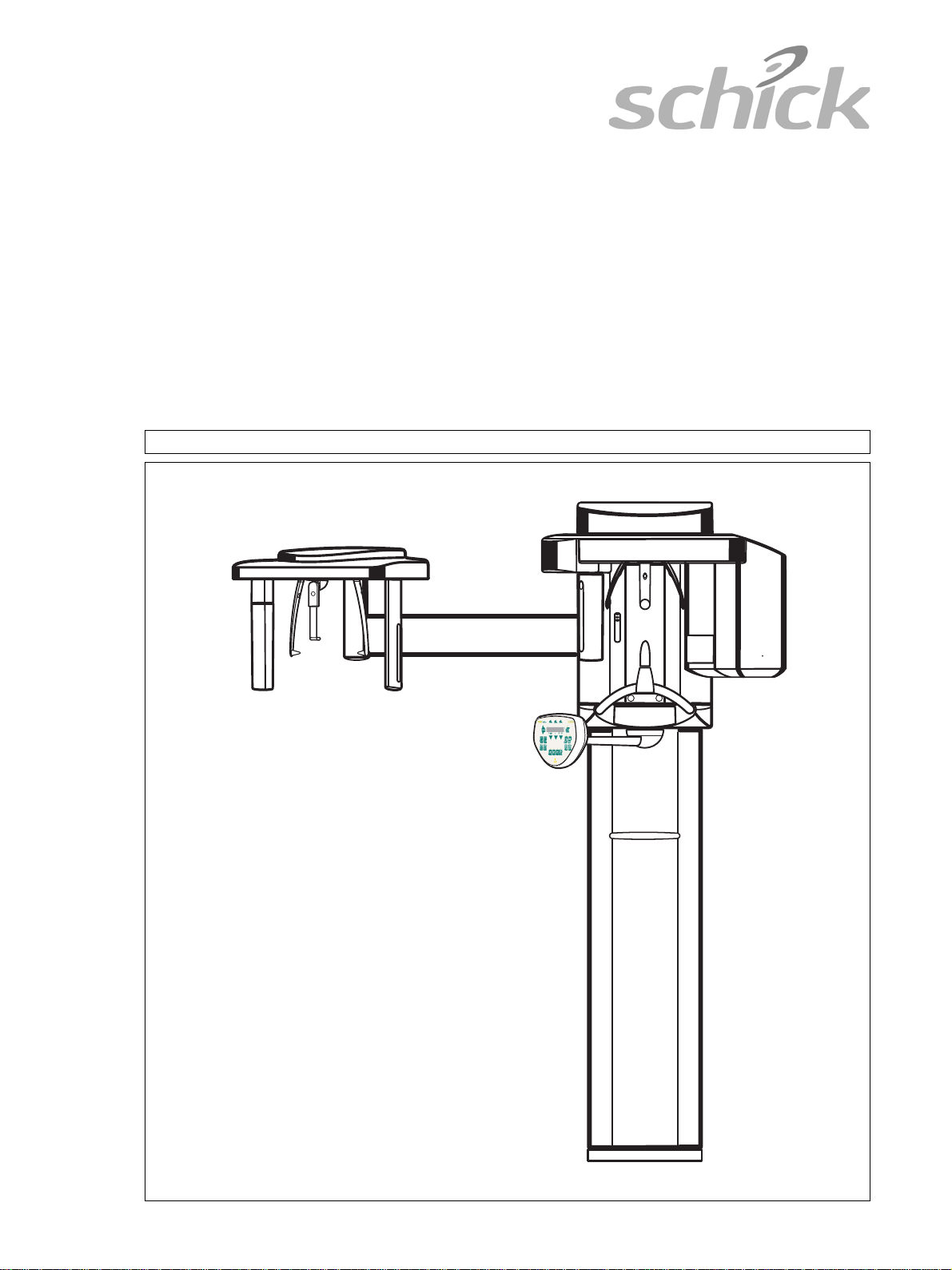
CDR PanElite
j~бенЙе~еЕЙ=fелнкмЕнбзел====
English
Page 2

Schick Technologies, Inc.
Maintenance Instructions CDR PanElite
General information
ATTENTION !
Proper shielding of room and operator
position is essential.
Since these requirements vary from state
to state it is the assembler's/installer's
responsibility that all local radiation
safety requirements are met.
61 88 085 D3352
2 D3352.103.02.01.02
Page 3

Schick Technologies, Inc.
Maintenance Instructions CDRPanElite
Contents
1 General................................................................................................................................ 5
2 Visual Check....................................................................................................................... 6
3 Indicator Lights and audible Signal.................................................................................. 7
4 Power supply adequacy.....................................................................................................9
5 kV – verification, kV ramp during panoramic exposure ............................................... 10
6 Tube Current Verification ................................................................................................ 14
7 Exposure Time Verification.............................................................................................17
8 Checking the X-Ray Beam...............................................................................................20
8.1 Diaphragm/system adjustment menu..................................................... 20
9 Checking the X-Ray Beam for panorama exposure......................................................22
9.1 Preparing the Pan adjustment........................................................ ........ 22
9.2 Checking the Pan sensor adjustment................................................ .. ... 23
9.3 Checking the Pan diaphragm adjustment................................. ... ........... 25
9.4 Checking the Pan filter adjustment.................................................... ..... 27
9.5 Checking the Pan symmetry................. .. ................................................ 29
10 Checking the X-Ray Beam for cephalometer exposure................................................ 31
10.1 Preparing the Ceph adjustment............................................. ... ... ........... 31
10.2 Checking the Ceph primary diaphragm adjustment................................ 32
10.3 Checking the Ceph rotation fixpoint adjustment..................................... 35
10.4 Checking the Ceph main X-ray beam direction adjustment.................... 37
11 Checking the alignment of the ear plugs....................................................................... 39
11.1 Preparing the ear plugs ......................................................... ................. 39
11.2 Checking the ear plug alignment........................................ .................... 40
12 Checking the laser............................................................................................................ 43
English
61 88 085 D3352
D3352.103.02.01.02
3
Page 4

Schick Technologies, Inc.
Maintenance Instructions CDRPanElite
61 88 085 D3352
4 D3352.103.02.01.02
Page 5
Schick Technologies, Inc. 1 General
ATTENTION
ATTENTION
ATTENTION
WARNING
ON
OFF
Maintenance Instructions CDR PanElite
1 General
To stay in compliance with the DHHS requirements the
CDR PanElite must be maintained annually.
It is the responsibility of the user to insure that the equipment is maintained with the manufacturer's recommended
Maintenance Instructions to insure compliance with the
Federal Performance Standard.
The manufacturer and the assembler/installer are relieved
from responsibility in those cases where the user fails to
have the manufacturer's recommended maintenance performed.
The actual maintenance inspection and consequent service must be accomplished by a trained serviceman. Neither the inspection nor service is part of the equipment warranty.
Technical instructions required
Operating Instructions
Service Manual
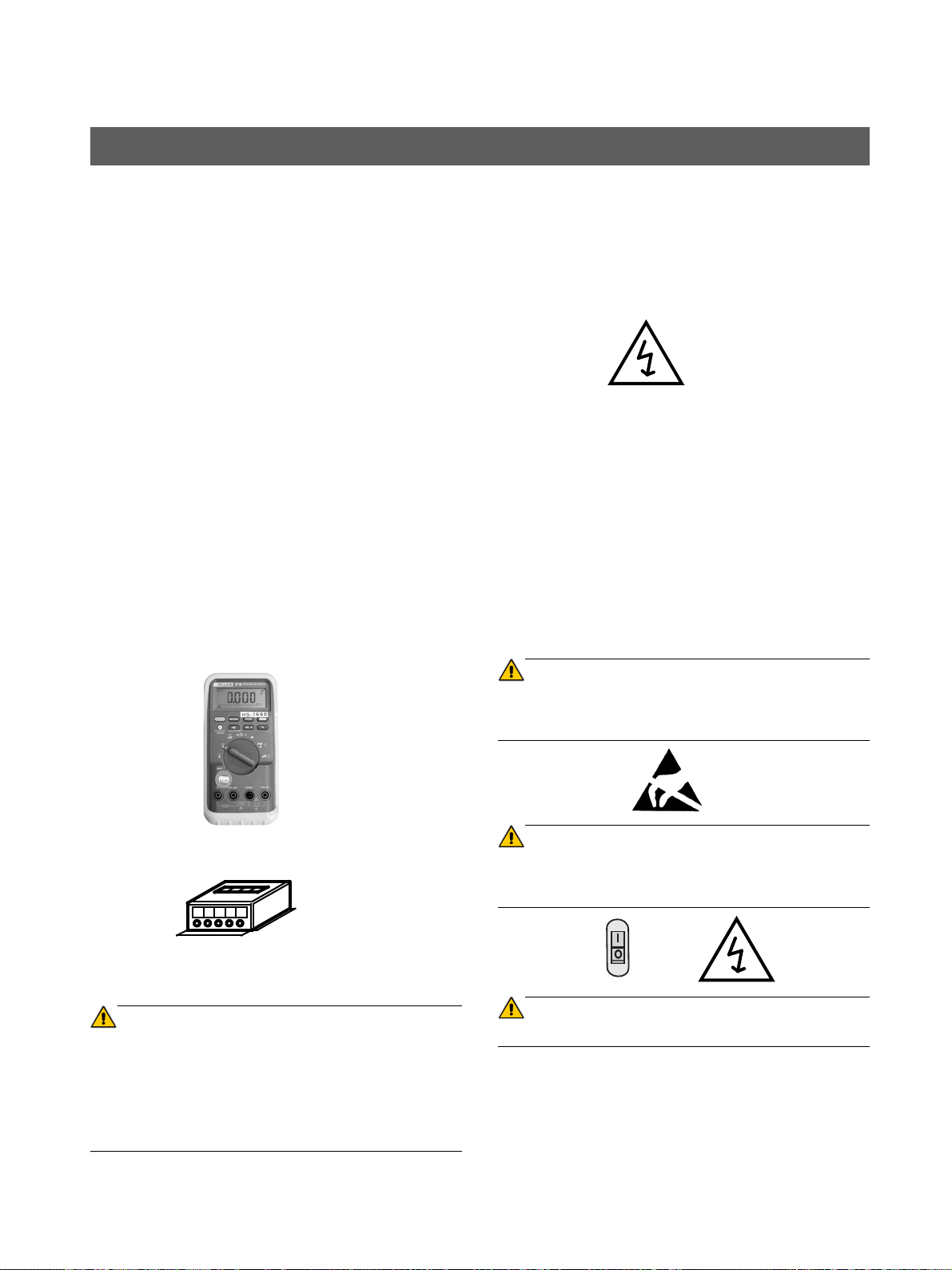
Instruments and adjustment tools required
All measuring devices must be suitable for measurements
on the mains potential.
This includes the pulse counter.
This means: A voltage of 1000 V between a connection and
ground must be possible.
1. Digital multimeter Fluke 87 III or equivalent.
Accuracy:
DC voltage ± 0.1 % of reading plus 0.02% of range
DC current ± 0.4 % of reading plus 0.1% of range.
Power Supply Adequacy
To assure that the CDR PanElite system performance is in
accordance with Schick specifications, an adequate power
supply for permanent installation is essential.
The Federal Performance Standard for diagnostic X-ray
units, code of Federal Regulations, Title 21 CFR, Subchapter J, mandates an adequate power supply.
Duty Cycle
Between exposures a minimum cool-off time is maintained
(automatic exposure blockage, see Operating Instructions
manual).
Operating Instructions
During measurements and adjustments it is necessary to
energize or de-energize the unit. For all operating steps
please refer to the Operating Instructions manual.
CAUTION with PC Boards!
All PC boards are fitted with electronic components sensi-
tive to electrostatic discharge (ESD). Electrostatic charges
are unavoidable due to friction caused by clothing, carpeting etc.
English
2. Electromechanical pulse counter, model KESSLER
ELLIS KT 203 ±1 pulse, or equivalent..
3. Adjustment set with alignment tool for X-ray beam , test
block and needle phantom delivered with the unit, (customer's property).
RADIATION!
Observe the radiation protection guide lines as outlined in
the Operating Instructions manual.
X-radiation is emitted as long as the exposure switch is depressed.
The X-ray indicator must light up on the Control Pad during
radiation. An acoustic signal should also be heard.
To prevent damage of electronic chips do not touch components.
Always handle circuit boards by their edges.
Electrical Shock Hazard!
Always turn unit OFF before connecting and disconnecting
the test leads to the test points
Life-threatening voltage on DX6.
61 88 085 D3352
D3352.103.02.01.02
5
Page 6
2 Visual Check Schick Technologies, Inc.
CDR PanElite
Service program
Software
Maintenance Instructions CDR PanElite
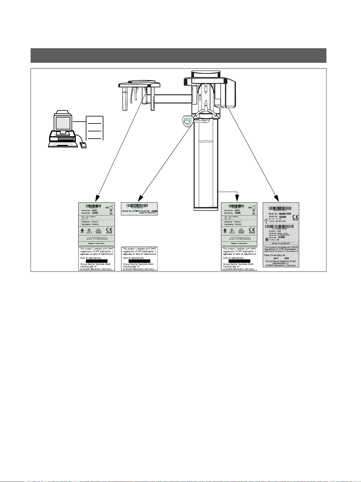
2 Visual Check
• Look for mechanical damage that may affect radiation
safety.
• Verify that all labels are affixed and legible.
Defaced labels must be replaced.
Order labels from Schick (address, see rear)
in writing stating:
• Customer Name
• Customer Address
All Model Numbers with Serial Numbers should be legible
on the unit for identification purposes. For serial numbers
see also Installation Report.
61 88 085 D3352
6 D3352.103.02.01.02
Page 7
Schick Technologies, Inc. 3 Indicator Lights and audible Signal
P1 14.1 64 8
Thisproductcomplies with DHHS
regulations21CFR Subchapter J,
applicableatdate of manufacture.
Dateofmanufacture:
SironaDentalSystems GmbH
Fabrikstraße31
D-64625Bensheim,Germany
Thisproductcomplies with DHHS
regulations21CFR Subchapter J,
applicableatdate of manufacture.
Dateofmanufacture:
SironaDentalSystems GmbH
Fabrikstraße31
D-64625Bensheim,Germany
P10
11.5
64
8
S
k
V
m
A
P 10
11.5
64
8
Program
s
k
V
m
A
Prog.
S
k
V
m
A
P 10
11.5
64
8
Program
WARNING:THISX-RAYUNIT MAY BE DANGEROUS TO PATIENT
ANDOPERATOR UNLESS SAFE EXPOSURE FACTORS AND OPERATING
INSTRUCTIONSARE OBSERVED.UNAUTHORIZEDUSE IS PROHIBITED.
WARNING:THIS X-RAY UNIT MAY BE DANGEROUS TO PATIENT
ANDOPERATOR UNLESS SAFE EXPOSURE FACTORS AND OPERATING
INSTRUCTIONSARE OBSERVED.UNAUTHORIZEDUSEIS PROHIBITED.
Remote
Radiation indicator
ON
OFF
Unit ON LED
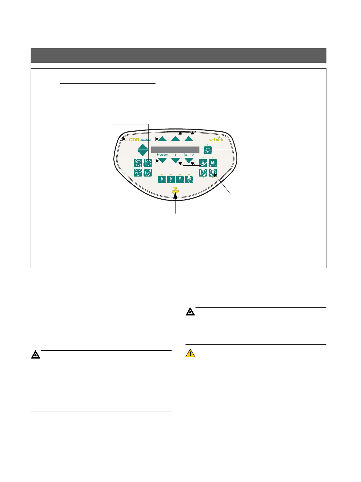
Maintenance Instructions CDR PanElite
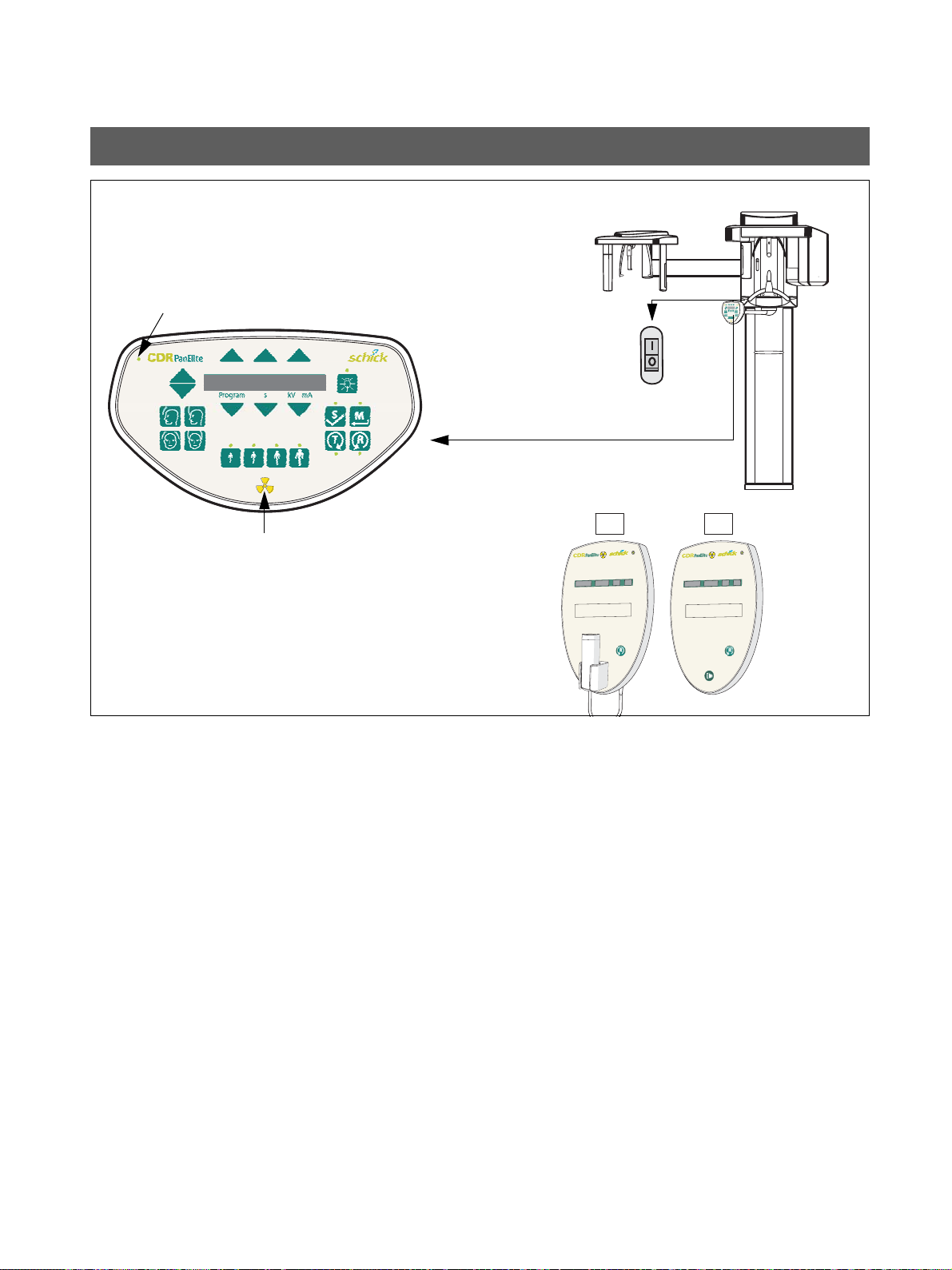
3 Indicator Lights and audible Signal
• Unit ON LED:
• Testing the keys and the functions on the user in-
Press the main switch to the ”
I” position to turn unit ON.
Power ON tests to take about 1 minute.
The ”Unit ON LED” in the upper right corner of the user
interface will then be lit".
terface.
– When the height is adjusted, an acoustic signal is
active.
– If the forehead support functions correctly, the max.
holding torque is still present.
– If remote is installed, test the remote keys and ver-
ify proper operation of the display.
– The exposure switch must not be defective or bro-
ken.
English
See also Operating Instructions under ”Preparing the Exposure” subchapter ”Switching the system on”.
61 88 085 D3352
D3352.103.02.01.02
7
Page 8
3 Indicator Lights and audible Signal Schick Technologies, Inc.
CAUTION RADIATION
CAUTION RADIATION
ATTENTION
P1 14.1 64 8
CAUTION RADIATION !
Observe Radiation Protection Guide Lines
see Operating Instructions
Unit ON LED
Return key R
menu keys
submenu key
Radiation indicator
Maintenance Instructions CDR PanElite
• Take an exposure:
– X-ray head must be in the initial position (If not,
press return key R).
– Make sure that CDR PanElite Service program is
ready to take an image.
For more details and possible error messages see
Operating Instructions.
– Set the
– Select
– Press and hold the exposure switch until the
exposure terminates automatically.
– The exposure ends when the rotation and radiation
switch off automatically.
– The radiation indication must light up during the
exposure period.
– Simultaneously an audible beep must sound at the
unit.
P1 exposure program using the menu keys.
68kV/8mA using submenu keys.
• Interrupt an exposure – deadman feature:
– Observe a cool-off time of max. 5 mins. between
exposures (automatic exposure blockage).
– Setting same as above.
– Press the exposure switch until X-ray lights up
and subsequently
terminate immediately. The radiation indicator
lights up.
Defective light indicators constitute a safety hazard to the
patient as well as to the operator.
The user is not permitted to use the unit, until repairs
are made!
release – the exposure must
8 D3352.103.02.01.02
61 88 085 D3352
Page 9
Schick Technologies, Inc. 4 Power supply adequacy
CAUTION RADIATION
NOTE
i
3.
1. 2.
n
K1
300 VAC
4. - 5.
K1
*
o
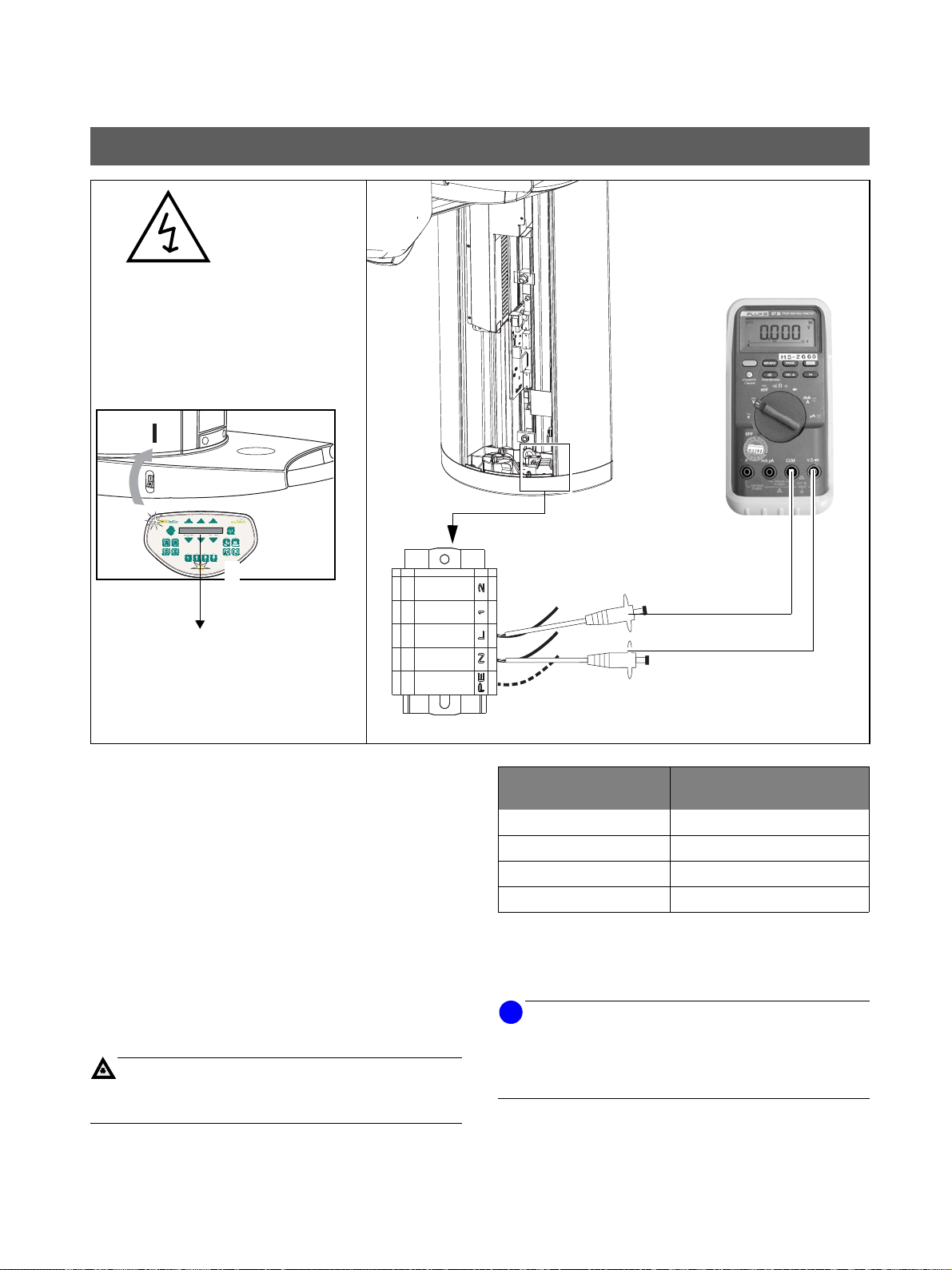
Maintenance Instructions CDR PanElite
4 Power supply adequacy
• To determine power supply adequacy, the line volt-
age drop
1. Be sure power is disconnected at the central distribu-
tion panel!
• Remove front cover (for details see Service Manual).
2. Select 300VAC line voltage range on multimeter .
Connect measuring leads to terminal K1, L and N.
3. Connect power and switch unit ON
Wait 1 min. for self-adjustment of the unit.
Press key R o to return X-ray tube head into the initial
position.
4. Make sure that CDR PanElite Service program is ready
to take an image.
5. Select highest exposure level e.g., 90kV/12mA.
– Press and hold the exposure switch until the meter
reading is obtained.
during exposure must be measured.
n.
Line voltage, no load: Max. permissible line volt-
age drop:
180 – 208V 9V
208 – 230V 8V
230 – 240V 7.5V
240 – 264V 7V
Record reading.
• Turn unit OFF.
• Remove meter leads and refit cover.
If the voltage drop is not within the specified range advise the customer, that an adequate power supply must be
installed. Refer to Pre-Installation Instructions.
Disconnect unit and do not release for use!
English
61 88 085 D3352
D3352.103.02.01.02
9
Page 10
5 kV – verification, kV ramp during panoramic exposure Schick Technologies, Inc.
WARNING
WARNING
ATTENTION
NOTE
i
NOTE
i
1.
2.
A
B
Maintenance Instructions CDR PanElite
5 kV – verification, kV ramp during panoramic
exposure
The electronics of the X-ray tube assembly are always
connected to line voltage.
Always switch the X-ray unit off and wait until V203 is
no longer illuminated before contacting the test leads.
The test leads and measuring instruments used must
have a dielectric strength of at least 1000V!
Be sure to use a battery-powered measuring instrument with shock-hazard-protected sockets.
Use only test leads with shock protection.
The X-ray tube assembly moves during the measurement.
Therefore, be sure to use test leads of sufficient length and
place the measuring instrument in a location where it is firmly seated so that it doesn’t fall down during rotation.
Measurements:
62kV correspond to 3.1V, tolerance +/-10%
During exposure the kV is increased in the central region
depending on kV/mA selected by up to 10%. This increase
can be measured in VDC.
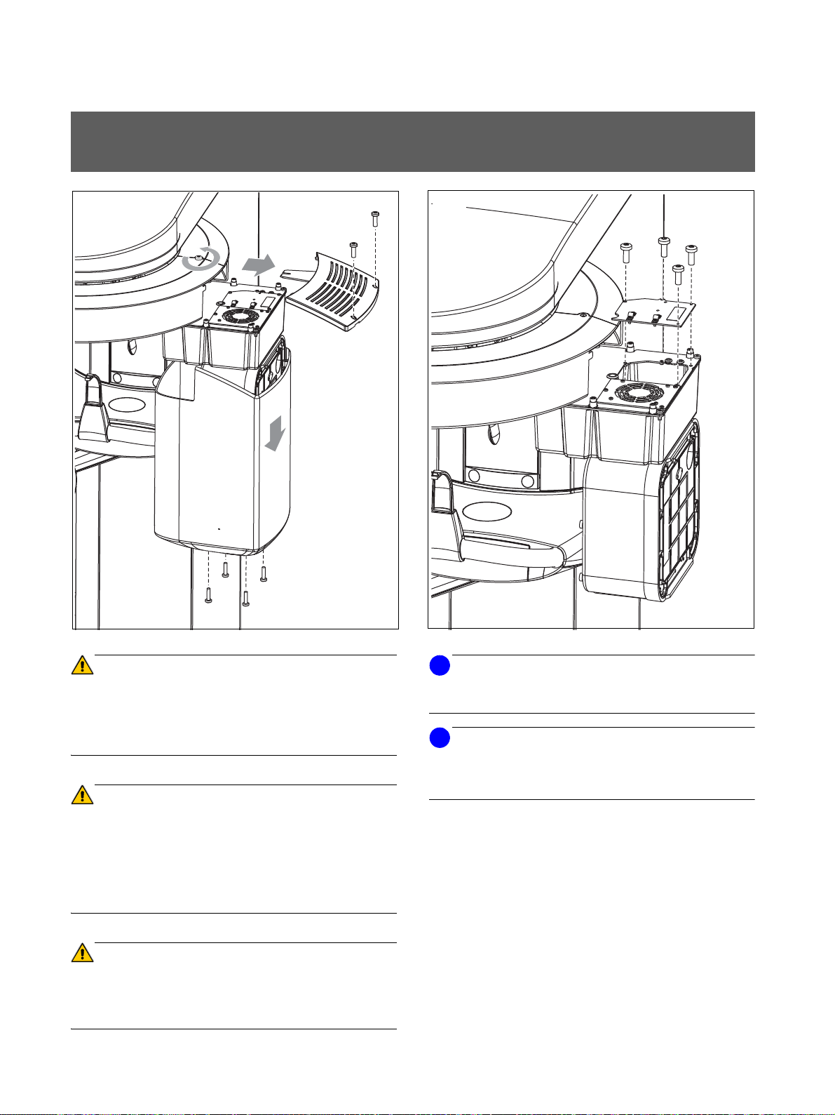
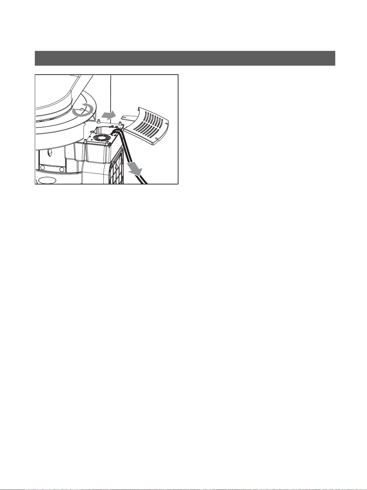
1. Remove cover (for details see Service Manual).
2. Remove the four screws A and remove cover plate B of
the electronics box.
61 88 085 D3352
10 D3352.103.02.01.02
Page 11
Schick Technologies, Inc. 5 kV – verification, kV ramp during panoramic exposure
CAUTION RADIATION
NOTE
i
3.
4.
5.
6. - 7.
KV– KV+
20VDC
com.
400 VDC
PC-board DX6
C
D
n
*
o
Maintenance Instructions CDR PanElite
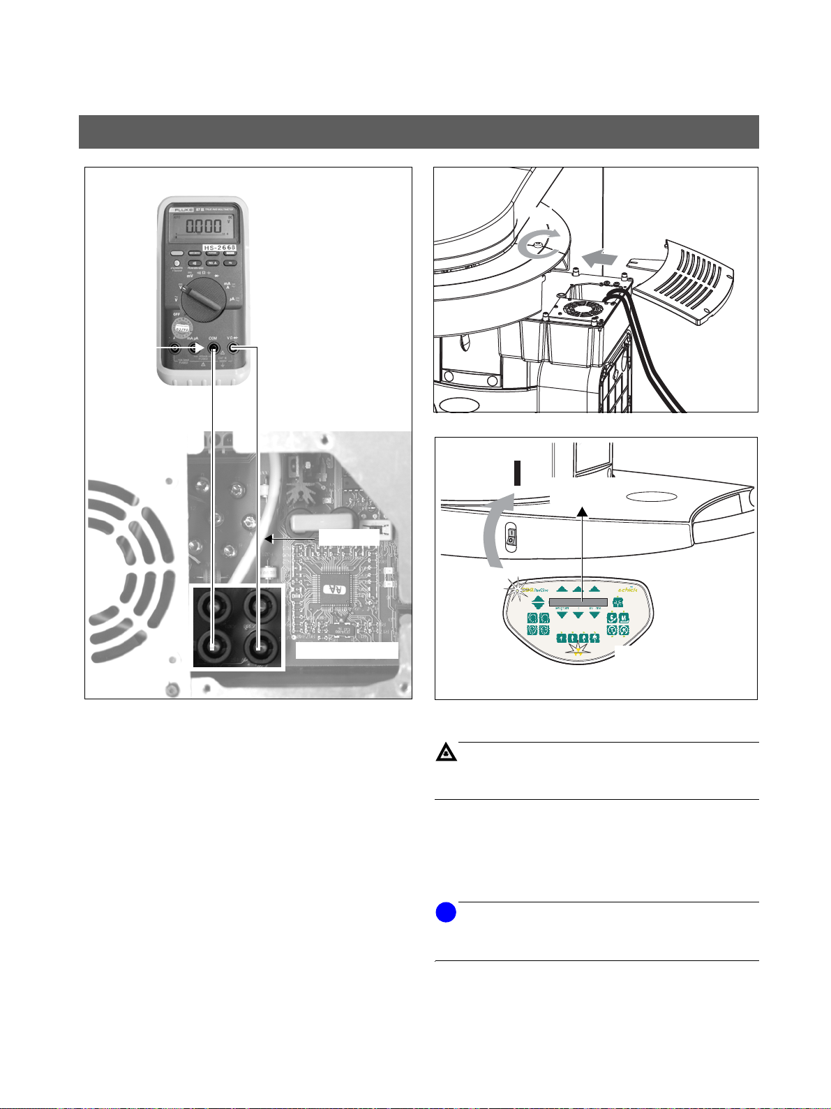
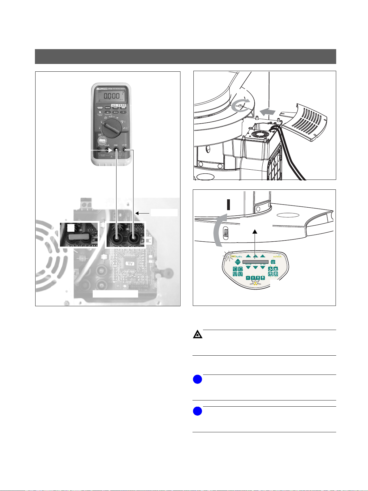
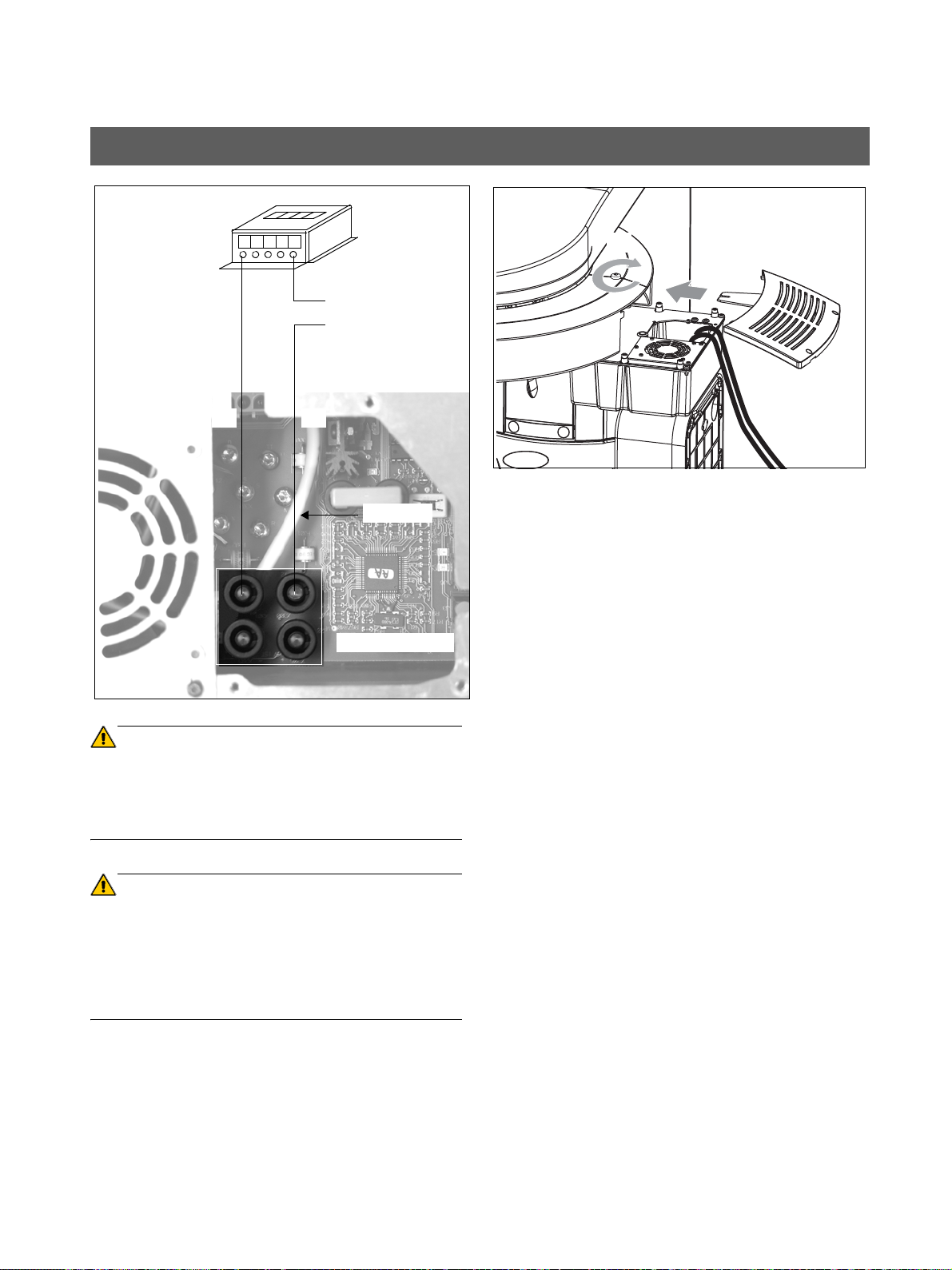
3. Connect digital voltmeter to KV+ and KV– test points on
PC board DX6 and select range 20 VDC.
4. Refit cover C and tighten screw D securely.
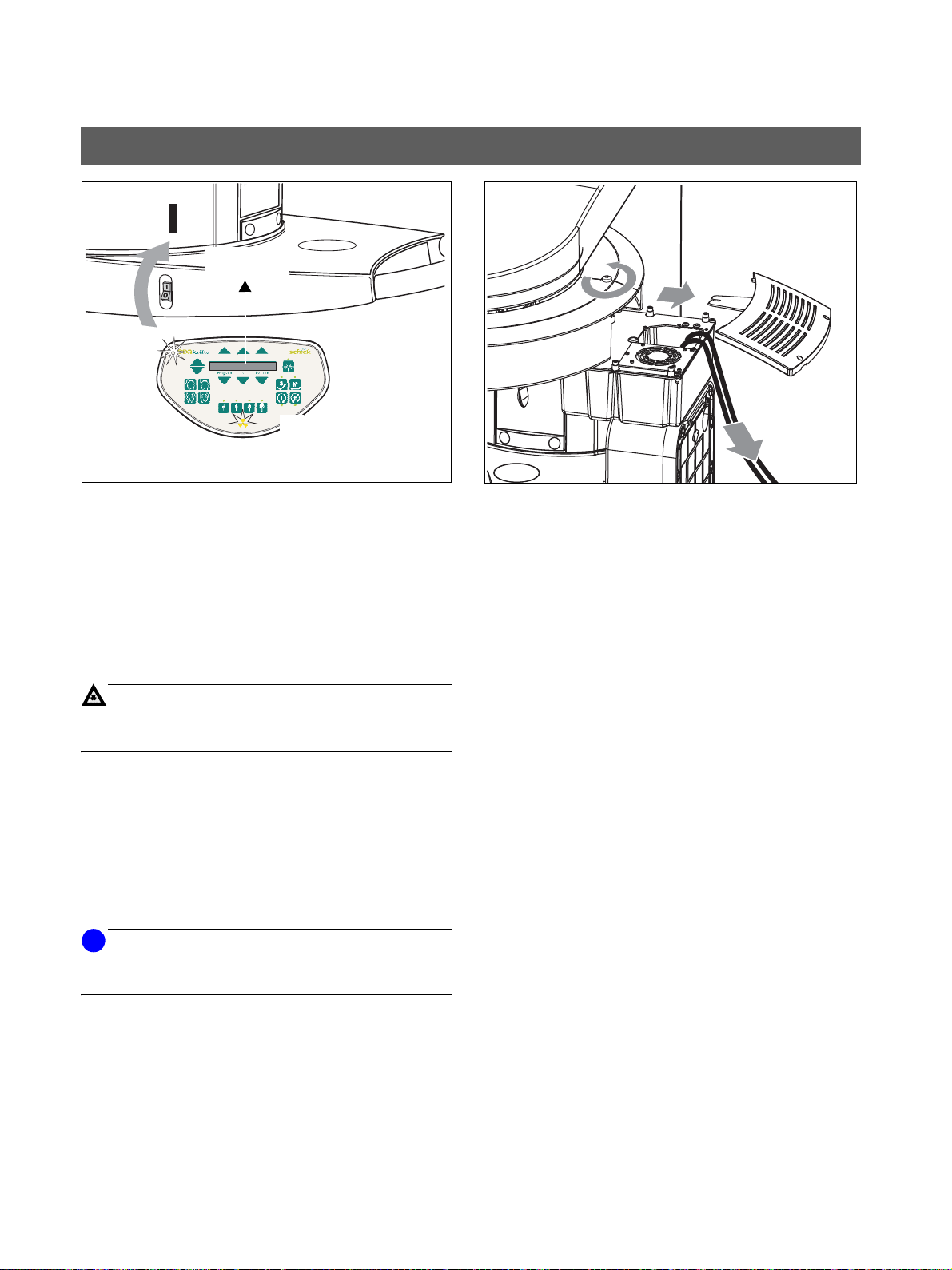
5. Switch unit ON
Wait 1 min. for power on of the unit.
Press key R
position.
6. Make sure that CDR PanElite Service program is ready
to take an image.
7. Select P1 program and 62kV/8mA.
n.
o to return X-ray tube head into the initial
Measurement:
– Press and hold the exposure switch until the
exposure terminates automatically.
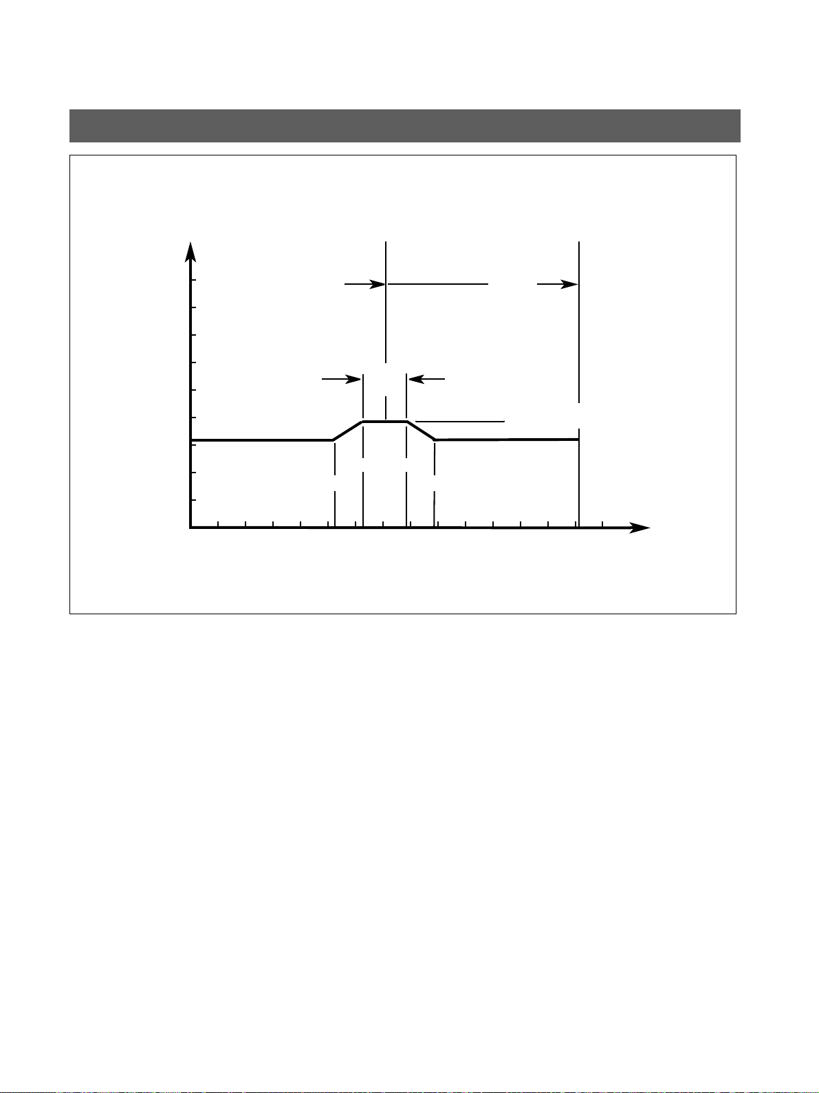
The following values must be obtained
(see also diagram on next page)
• up to 5.25 seconds:
• from 6.25 to 7.85 s KV-ramp: e.g., 4 V ±0.4V
• after 8.85 seconds:
3.1 V ±0.3V
3 V ±0.3V
English
61 88 085 D3352
D3352.103.02.01.02
If specified values cannot be obtained, see Service Manual for troubleshooting.
11
Page 12
5 kV – verification, kV ramp during panoramic exposure Schick Technologies, Inc.
15
ramp
max. 4.05V
min. 3.45V
VDC
s
Exposure time
0 2
1
2
3
4
5
6
7
8
9
1 104 5 6 7 8 9 11 12 13 143
5.25s 8.85s
ramp
1.6s
14.1s
Complete P1
exposure
time
7.05s
max. 3.41V
min. 2.79V
6.25s 7.85s
Nominal 3.1V
Nominal 4.0V
Maintenance Instructions CDR PanElite
kV – Verification, kV–ramp during panoramic exposure
kV ramp diagram
with program P1 and 62kV/8mA set on the Control Pad and
temple support fully open.
12 D3352.103.02.01.02
61 88 085 D3352
Page 13
Schick Technologies, Inc. 5 kV – verification, kV ramp during panoramic exposure
8.
Maintenance Instructions CDR PanElite
• Turn unit OFF.
8. Remove top cover and meter leads.
English
61 88 085 D3352
D3352.103.02.01.02
13
Page 14
6 Tube Current Verification Schick Technologies, Inc.
WARNING
WARNING
WARNING
Maintenance Instructions CDR PanElite
6 Tube Current Verification
The electronics of the X-ray tube assembly are always
connected to line voltage.
Always switch the X-ray unit off and wait until V203 is
no longer illuminated before contacting the test leads.
The test leads and measuring instruments used must
have a dielectric strength of at least 1000V!
Be sure to use a battery-powered measuring instrument with shock-hazard-protected sockets.
Use only test leads with shock protection.
Be sure to switch the X-ray unit off before removing the
jumper for the mA measuring jack.
14 D3352.103.02.01.02
61 88 085 D3352
Page 15
Schick Technologies, Inc. 6 Tube Current Verification
CAUTION RADIATION
NOTE
i
NOTE
i
C
D
1. 2.
MA+MA-
20VDC
com.
PC-board DX6
·
A
400 VDC
3.
4. - 5.
n
*
o
Maintenance Instructions CDR PanElite
1. Remove shunt jumper A from MA+/MA – test points on
PC board DX6. Connect digital multimeter to VDC and
select range 20 mVDC.
2. Reattach cover C and tighten screw D securely.
3. Switch unit ON
Wait 1 min. for self-adjustment of the unit.
Press key R o to return X-ray tube head into the initial
position.
4. Select 66kV/8mA. Make sure that CDR PanElite Service program is ready to take an image.
5. If P1 program and 66kV/8mA are selected .
The unit must be ready for radiation.
n.
Measurement:
– Press and hold the exposure switch until meter
reading is obtained.
The multimeter shall indicate 8mV ±1.6mV.
Record reading.
Readings: 1mV corresponds to a tube current of 1mA, toler-
ance +/-20%.
English
61 88 085 D3352
D3352.103.02.01.02
If specified values cannot be obtained, see Service Manual, chapter ”Tube Current Verification”.
15
Page 16
6 Tube Current Verification Schick Technologies, Inc.
6.
• If specified value is obtained switch unit OFF.
6. Remove upper cover and meter leads
• Replace jumper!
Maintenance Instructions CDR PanElite
61 88 085 D3352
16 D3352.103.02.01.02
Page 17
Schick Technologies, Inc. 7 Exposure Time Verification
WARNING
WARNING
C
D
400 VDC
PC board DX6
1.
to N
to L
T2
of 110VAC/60Hz
power receptacle
T1
Pulse counter
2.
Maintenance Instructions CDR PanElite
7 Exposure Time Verification
The electronics of the X-ray tube assembly are always
connected to line voltage.
Always switch the X-ray unit off and wait until V203 is
no longer illuminated before contacting the test leads.
The test leads and measuring instruments used must
have a dielectric strength of at least 1000V!
Be sure to use a battery-powered measuring instrument with shock-hazard-protected sockets.
Use only test leads with shock protection.
1. Connect...
– test point
110V power receptacle
– the common lead of the pulse counter to
110V power receptacle
– the second measuring lead of the pulse counter to
test point T1
2. Refit cover C and tighten screw D securely.
T2 of terminal on PC board DX6 to L of
English
N of the
61 88 085 D3352
D3352.103.02.01.02
17
Page 18
7 Exposure Time Verification Schick Technologies, Inc.
CAUTION RADIATION
NOTE
i
6.3.
4. - 5.
n
*
o
3. Switch unit ON n.
Wait 1 min. for power on of the unit.
Press key R o to return X-ray tube head to the initial
position.
4. Select 66kV/8mA.
Make sure that CDR PanElite Service program is ready
to take an image.
Maintenance Instructions CDR PanElite
Measurement:
– Press and hold the exposure switch until the exposure terminates automatically.
5. Select service routine S2 (Selecting a service routine:
See Service Manual):
• Set radiation time to 1 sec.
• Measured values at 50 Hz 50 pulses +/-10%
• Measured values at 60 Hz 60 pulses +/-10%
Record average pulse count.
If specified value cannot be obtained, see Service Manual, chapter ”Exposure Time Verification”.
• If specified value is obtained, switch unit OFF.
6. Remove upper cover and meter leads.
18 D3352.103.02.01.02
61 88 085 D3352
Page 19

Schick Technologies, Inc. 7 Exposure Time Verification
7. 8.
Maintenance Instructions CDR PanElite
7. Screw the cover plate back on to the electronics box.
8. Reattach the housing covers.
English
61 88 085 D3352
D3352.103.02.01.02
19
Page 20

8 Checking the X-Ray Beam Schick Technologies, Inc.
NOTE
i
NOTE
i
SERVICE
2.
1.
8.1 Diaphragm/system adjustment menu Maintenance Instructions CDR PanElite
8 Checking the X-Ray Beam
8.1 Diaphragm/system adjustment menu
The
DIAPHRAGM/SYSTEM ADJUSTMENT
you through the adjustment of the panoramic unit and the
cephalometer. This service routine is started from CDR
PanElite Service program:
UTILITIES
X-RAY DEVICE
SYSTEM ADJUSTMENT
The
word-protected. As password, enter the first four digits of
the current system date (PC) in reverse order.
Example: On 05/30/2004, the service password is 5003
Æ
CONSTANCY TEST
Æ
SERVICE EXPOSURE
DIAPHRAGM/SYSTEM ADJUSTMENT
Æ
menu guides
XCXP
Æ
Æ
DIAPHRAGM
menu is pass-
SELECT
When you open the
menu, the unit switches from the user mode to the PC service mode logged by the PC.
This mode is indicated by the message SERVICE (2.) on
the Control Pad. In PC service mode, the Control Pad control options are determined by CDR PanElite Service program and the currently selected service routine. General
/
control of the unit by means of the Control Pad (as in the user mode) is not possible in this mode.
DIAPHRAGM/SYSTEM ADJUSTMENT
20 D3352.103.02.01.02
61 88 085 D3352
Page 21

Schick Technologies, Inc. 8 Checking the X-Ray Beam
Maintenance Instructions CDR PanElite 8.1 Diaphragm/system adjustment menu
The
DIAPHRAGM/SYSTEM ADJUSTMENT
11 submenus:
menu has
z Pan - Sensor adjustment
z Pan - Diaphragm
z Pan - Filter
z Pan - Symmetry
z Ceph - Primary diaphragm
z Ceph - Fixed point of rotation
z Ceph - Main X-ray beam direction
z Pan - Reset adjustment
z Ceph - Reset adjustment
You can change between the individual submenus by clicking the tabs with the mouse. To quit the
SYSTEM ADJUSTMENT
menu, click
DIAPHRAGM
CANCEL
/
.
English
61 88 085 D3352
D3352.103.02.01.02
21
Page 22

9 Checking the X-Ray Beam for panorama exposure Schick Technologies, Inc.
NOTE
i
1. 2.
A
Needles on
top side
9.1 Preparing the Pan adjustment Maintenance Instructions CDR PanElite
9 Checking the X-Ray Beam for panorama exposure
9.1 Preparing the Pan adjustment
In order to perform the PAN sensor adjustment and the
symmetry adjustment you must insert needle phantom A
in the bite block holder of the panoramic X-ray unit.
The needle phantom must be removed from the bite block
holder for the pan diaphragm adjustment.
When fitting the needle phantom, make sure that it is
correctly oriented. For the adjustment of the X-ray unit, the
phantom must be fitted in such a way that the needles
point upward (2.).
61 88 085 D3352
22 D3352.103.02.01.02
Page 23

Schick Technologies, Inc. 9 Checking the X-Ray Beam for panorama exposure
NOTE
i
Connection made
Exposure
Preview
Quit
Quit
1.
2.
in CDRPanElite Service program
on the Control Pad
60/3 0.6
Maintenance Instructions CDR PanElite 9.2 Checking the Pan sensor adjustment
9.2 Checking the Pan sensor adjustment
• Plug the sensor into the sensor slot on the panoramic
X-ray unit.
• Insert the needle phantom in the bite block holder of the
panoramic X-ray unit (see page 22).
1. Open the
The menu provides a precision adjustment and a
coarse adjustment. Always try to use precision adjustment first when adjusting the unit. In most cases, it is
not necessary to perform a coarse adjustment prior to
precision adjustment.
PAN - SENSOR ADJUSTMENT submenu.
English
• The exposure dialog box showing the exposure status
appears in CDR PanElite Service program.
• The initialization status is visualized by a progress indicator on the Control Pad.
• The initialization procedure is completed when the exposure parameters of service routine S010.1
(60 kV/3 mA; 0.6 s) are displayed and the progress indicator disappears.
2. Make sure that CDR PanElite Service program is ready
61 88 085 D3352
D3352.103.02.01.02
to take an image:
Click IMAGE ACQUISITION.
23
Page 24

9 Checking the X-Ray Beam for panorama exposure Schick Technologies, Inc.
NOTE
i
4.
Adjustment: ok
3.
9.2 Checking the Pan sensor adjustment Maintenance Instructions CDR PanElite
3. Take an exposure (60 kV/3 mA):
– Press the R key to move the unit back to the
starting position.
– Press the exposure switch. Hold down the expo-
sure switch until image acquisition is completed
and the preview image appears in the exposure
dialog box.
If the criteria specified above are not fulfilled, the sensor
must be adjusted. The procedure for adjusting the unit is described in the service manual.
4. Evaluate the exposed image:
– The three needle images must lie in the center
of the exposed areas and inside the auxiliary
lines (see image 4.).
61 88 085 D3352
24 D3352.103.02.01.02
Page 25

Schick Technologies, Inc. 9 Checking the X-Ray Beam for panorama exposure
NOTE
i
1.
2.
in CDRPanElite Service program
on the Control Pad
60/3 0.20
,
Connection made
Exposure
Preview
Quit
Quit
Maintenance Instructions CDR PanElite 9.3 Checking the Pan diaphragm adjustment
9.3 Checking the Pan diaphragm
• Remove the needle phantom from the bite block holder
of the panoramic X-ray unit.
1. Change to the
The menu provides a precision adjustment and a
coarse adjustment. Always try to use precision adjustment first when adjusting the unit. In most cases, it is
not necessary to perform a coarse adjustment prior to
precision adjustment.
adjustment
PAN - DIAPHRAGM submenu.
English
• The initialization status is visualized by a progress indicator on the Control Pad.
• The initialization procedure is completed when the exposure parameters of service routine S030.2
(60 kV/3 mA; 0.6 s) are displayed and the progress indicator disappears.
2. Make sure that CDR PanElite Service program is ready
to take an image:
Click
• The exposure dialog box showing the exposure status
appears in CDR PanElite Service program.
61 88 085 D3352
D3352.103.02.01.02
IMAGE ACQUISITION.
25
Page 26

9 Checking the X-Ray Beam for panorama exposure Schick Technologies, Inc.
NOTE
i
4.
Adjustment: ok
3.
9.3 Checking the Pan diaphragm adjustment Maintenance Instructions CDR PanElite
3. Take an exposure (60 kV/3 mA):
– Press the R key to move the unit back to the
starting position.
– Press the exposure switch. Hold down the expo-
sure switch until image acquisition is completed
and the preview image appears in the exposure
dialog box.
– The exposed diaphragm area must lie horizon-
tally centered in the image field as well as
inside the superimposed auxiliary lines.
– A white border surrounding the image on all
sides must be visible. The maximum density
must lie in the center of the diaphragm area.
4. Evaluate the exposed image:
If the current image differs from the ideal image (see image
4.), the diaphragm must be adjusted. The procedure for adjusting the unit is described in the service manual.
61 88 085 D3352
26 D3352.103.02.01.02
Page 27

Schick Technologies, Inc. 9 Checking the X-Ray Beam for panorama exposure
on the Control Pad
60/3 0.20
1.
2.
in CDRPanElite Service program
Connection made
Exposure
Preview
Quit
Quit
Maintenance Instructions CDR PanElite 9.4 Checking the Pan filter adjustment
9.4 Checking the Pan filter adjustment
1. Change to the PAN - FILTER submenu.
2. Make sure that CDR PanElite Service program is ready
to take an image:
Click
• The exposure dialog box showing the exposure status
appears in CDR PanElite Service program.
• The initialization status is visualized by a progress indicator on the Control Pad.
• The initialization procedure is completed when the exposure parameters of service routine S030.3
(60 kV/3 mA; 0.6 s) are displayed and the progress indicator disappears.
English
IMAGE ACQUISITION.
61 88 085 D3352
D3352.103.02.01.02
27
Page 28

9 Checking the X-Ray Beam for panorama exposure Schick Technologies, Inc.
NOTE
i
4.
Adjustment: ok
3.
9.4 Checking the Pan filter adjustment Maintenance Instructions CDR PanElite
3. Take an exposure (60 kV/3 mA):
– Press the R key to move the unit back to the
starting position.
– Press the exposure switch. Hold down the expo-
sure switch until image acquisition is completed
and the preview image appears in the exposure
dialog box.
If the current image differs from the ideal image (see image
4.), the diaphragm must be adjusted. The procedure for adjusting the unit is described in the service manual.
4. Evaluate the exposed image:
– The superimposed filter must cover one half of
the diaphragm (see image 4.).
61 88 085 D3352
28 D3352.103.02.01.02
Page 29

Schick Technologies, Inc. 9 Checking the X-Ray Beam for panorama exposure
1.
2.
in CDRPanElite Service program
on the Control Pad
60/314.1
Connection made
Exposure
Preview
Quit
Quit
Maintenance Instructions CDR PanElite 9.5 Checking the Pan symmetry
9.5 Checking the Pan symmetry
• Insert the needle phantom in the bite block holder of the
panoramic X-ray unit (see page 22).
1. Change to the
2. Make sure that CDR PanElite Service program is ready
to take an image:
Click
• The exposure dialog box showing the exposure status
appears in CDR PanElite Service program.
• The initialization status is visualized by a progress indicator on the Control Pad.
• The initialization procedure is completed when the exposure parameters of service routine S010.2
(60 kV/3 mA; 0.6 s) are displayed and the progress indicator disappears.
English
PAN - SYMMETRY submenu.
IMAGE ACQUISITION.
61 88 085 D3352
D3352.103.02.01.02
29
Page 30

9 Checking the X-Ray Beam for panorama exposure Schick Technologies, Inc.
NOTE
i
Adjustment: ok
4.
3.
A2 = 44.3 ± 0.5 mm
A1 = 88.6 mm ± 1 mm
± 0.75 mm
ZOOM: 1:1
A2 = 44.3 ± 0.5 mm
A2 A2
± 0.75 mm
9.5 Checking the Pan symmetry Maintenance Instructions CDR PanElite
3. Take an exposure (60 kV/3 mA):
– Press the R key to move the unit back to the
starting position.
– Press the exposure switch. Hold down the expo-
sure switch until image acquisition is completed
and the preview image appears in the exposure
dialog box.
4. Evaluate the captured image.
- The shadow of the center needle, the needle im-
age and the auxiliary line must be aligned.
A tolerance (offset of needle from the central
auxiliary line) of
± 0.75
mm is admissible.
- Distance A1 must be 88.6
- Distances A2 must be 44.3
- A white border surrounding the image on all
sides must be visible (when zoomed out fully).
If these criteria are not fulfilled, the symmetry must be adjusted. The procedure for adjusting the unit is described in
the service manual.
± 1
± 0.5
mm.
mm.
30 D3352.103.02.01.02
61 88 085 D3352
Page 31

Schick Technologies, Inc. 10 Checking the X-Ray Beam for cephalometer exposure
1.
B
Maintenance Instructions CDR PanElite 10.1 Preparing the Ceph adjustment
10 Checking the X-Ray Beam for cephalometer
exposure
English
10.1 Preparing the Ceph adjustment
Insert test phantom B in the sensor slot on the panoramic
X-ray unit in order to perform the adjustment of the Ceph
primary diaphragm and the adjustment of the Ceph
main X-ray beam direction.
The test phantom must be removed from the sensor slot on
the panoramic X-ray unit for the adjustment of the Ceph
fixed point of rotation and for the Ceph quickshot.
61 88 085 D3352
D3352.103.02.01.02
31
Page 32

10 Checking the X-Ray Beam for cephalometer exposure Schick Technologies, Inc.
1.
2.
in CDRPanElite Service program
on the Control Pad
80/14 14.9
Connection made
Exposure
Preview
Quit
Quit
10.2 Checking the Ceph primary diaphragm adjustment Maintenance Instructions CDR PanElite
10.2 Checking the Ceph primary diaphragm
adjustment
• Move the ear plug holders on the cephalometer
completely apart and swing them out of the beam direction (ap).
• Insert the test phantom in the sensor slot on the pan-
oramic X-ray unit (see page 31).
• Plug the sensor into the sensor slot on the cephalome-
ter.
• Open the DIAPHRAGM/SYSTEM ADJUSTMENT
menu.
1. Select the CEPH - PRIMARY DIAPHRAGM submenu.
2. Make sure that CDR PanElite Service program is ready
to take an image:
Click IMAGE ACQUISITION.
• The exposure dialog box showing the exposure status
appears in CDR PanElite Service program.
• The initialization status is visualized by a progress indicator on the Control Pad.
• The initialization procedure is completed when the exposure parameters of service routine S010.3
(60 kV/3 mA; 0.6 s) are displayed and the progress indicator disappears.
61 88 085 D3352
32 D3352.103.02.01.02
Page 33

Schick Technologies, Inc. 10 Checking the X-Ray Beam for cephalometer exposure
3.
Maintenance Instructions CDR PanElite 10.2 Checking the Ceph primary diaphragm adjustment
3. Take an exposure (80 kV/14 mA):
– Press the R key to move the unit back to the
starting position.
– Press the exposure switch. Hold down the expo-
sure switch until image acquisition is completed
and the preview image appears in the exposure
dialog box.
English
61 88 085 D3352
D3352.103.02.01.02
33
Page 34

10 Checking the X-Ray Beam for cephalometer exposure Schick Technologies, Inc.
NOTE
i
NOTE
i
NOTE
i
4.
Adjustment: ok
S2
S2
S3 = approx. 60 mm
V61_1
(must be installed
vertically)
10.2 Checking the Ceph primary diaphragm adjustment Maintenance Instructions CDR PanElite
If S3 is significantly larger than 60 mm, check whether optical switch V61_1 (LB on the horizontal diaphragm slider) is
properly installed. If necessary, correct the alignment of the
light barrier and then repeat the entire Pan and Ceph adjustment procedure.
4. Evaluate the captured image.
– The vertical pin must be horizontally centered
in the exposed image area.
– A uniform white border surrounding the image
on all sides must be visible.
– Distance S3 must be approx. 60 mm.
A slight vertical offset of the grid is permissible.
34 D3352.103.02.01.02
If the image differs from the ideal image 4., the Ceph primary diaphragm must be readjusted. The procedure for adjusting the unit is described in the service manual.
61 88 085 D3352
Page 35

Schick Technologies, Inc. 10 Checking the X-Ray Beam for cephalometer exposure
NOTE
i
1.
2.
in CDRPanElite Service program
on the Control Pad
80/14 0.60
Connection made
Exposure
Preview
Quit
Quit
Maintenance Instructions CDR PanElite 10.3 Checking the Ceph rotation fixpoint adjustment
10.3 Checking the Ceph rotation fixpoint
adjustment
• Remove the Ceph test phantom from the sensor slot of
the panoramic X-ray unit.
1. Change to the
submenu.
The menu provides a precision adjustment and a
coarse adjustment. Always try to use precision adjustment first when adjusting the unit. In most cases, it is
not necessary to perform a coarse adjustment prior to
precision adjustment.
2. Make sure that CDR PanElite Service program is ready
to take an image:
Click
CEPH - FIXED POINT OF ROTATION
IMAGE ACQUISITION.
English
• The exposure dialog box showing the exposure status
appears in CDR PanElite Service program.
• The initialization status is visualized by a progress indicator on the Control Pad.
• The initialization procedure is completed when the exposure parameters of service routine S010.5
(60 kV/3 mA; 0.6 s) are displayed and the progress indicator disappears.
61 88 085 D3352
D3352.103.02.01.02
35
Page 36

10 Checking the X-Ray Beam for cephalometer exposure Schick Technologies, Inc.
NOTE
i
4.
Adjustment: ok
3.
10.3 Checking the Ceph rotation fixpoint adjustment Maintenance Instructions CDR PanElite
3. Take an exposure (80 kV/14 mA):
– Press the R key to move the unit back to the
starting position.
– Press the exposure switch. Hold down the expo-
sure switch until image acquisition is completed
and the preview image appears in the exposure
dialog box.
4. Evaluate the exposed image:
– The exposed diaphragm area must lie centered
and straight in the image field as well as inside
the superimposed auxiliary lines (see image 4.).
– A white border surrounding the image on all
sides must be visible.
If the criteria specified above are not fulfilled, the Ceph fixed
point of rotation must be adjusted. The procedure for adjusting the unit is described in the service manual.
61 88 085 D3352
36 D3352.103.02.01.02
Page 37

Schick Technologies, Inc. 10 Checking the X-Ray Beam for cephalometer exposure
1.
2.
in CDRPanElite Service program
80/14 14.9
Connection made
Exposure
Preview
Quit
Quit
Maintenance Instructions CDR PanElite 10.4 Checking the Ceph main X-ray beam direction adjustment
10.4 Checking the Ceph main X-ray beam
direction adjustment
• Insert the test phantom in the sensor slot on the pan-
oramic X-ray unit (see page 31).
• Swing the ear plug holders out of the beam direction.
1. Change to the
DIRECTION submenu.
2. Make sure that CDR PanElite Service program is ready
to take an image:
Click
• The exposure dialog box showing the exposure status
appears in CDR PanElite Service program.
• The initialization status is visualized by a progress indi-
cator on the Control Pad.
CEPH - MAIN X-RAY BEAM
IMAGE ACQUISITION.
English
• The initialization procedure is completed when the exposure parameters of service routine S010.6
(60 kV/3 mA; 0.6 s) are displayed and the progress indicator disappears.
61 88 085 D3352
D3352.103.02.01.02
37
Page 38

NOTE
i
4.
Adjustment: ok
10 mm
10 mm
10 mm
10 mm
3.
10 Checking the X-Ray Beam for cephalometer exposure Schick Technologies, Inc.
10.4 Checking the Ceph main X-ray beam direction adjustment Maintenance Instructions CDR PanElite
3. Take an exposure (80 kV/14 mA):
38 D3352.103.02.01.02
– Press the R key to move the unit back to the
starting position.
– Press the exposure switch. Hold down the expo-
sure switch until image acquisition is completed
and the preview image appears in the exposure
dialog box.
4. Evaluate the exposed image:
– A horizontal bar must be visible in the center of
the image (see image 4.). If this bar is visible,
the exposure is OK and ...
– the two beams imaged are within the tolerance
band of ± 10 mm (see image 4.).
If the criteria specified above are not fulfilled, the Ceph main
X-ray beam direction must be adjusted. The procedure for
adjusting the unit is described in the service manual.
61 88 085 D3352
Page 39

Schick Technologies, Inc. 11 Checking the alignment of the ear plugs
NOTE
i
1.
2.
D
3.
Maintenance Instructions CDR PanElite 11.1 Preparing the ear plugs
11 Checking the alignment of the ear plugs
11.1 Preparing the ear plugs
The sensor must be plugged into the sensor slot on the
cephalometer. No sensor may be plugged into the sensor
slot on the panoramic X-ray unit.
• Select the
CEPH mode on the Control Pad.
English
1. Move the ear plug holders completely apart and swing
them into the beam direction.
2. Fit adjusting caps D onto the ear plugs and secure them
with adhesive tape.
Black adjusting cap on the outside (sensor side),
Transparent adjusting cap on the inside (tube assembly side).
3. Unscrew the top cover from the cephalometer.
61 88 085 D3352
D3352.103.02.01.02
39
Page 40

11 Checking the alignment of the ear plugs Schick Technologies, Inc.
1. 2.
3.
4.
11.2 Checking the ear plug alignment Maintenance Instructions CDR PanElite
11.2 Checking the ear plug alignment
1. In CDR PanElite Service program, select the constancy
test:
UTILITIES ‡ CONSTANCY TEST
The typical CDR PanElite Service program user interface is started. The constancy test is preset.
2. Start the exposure mode:
XCXP
Click
The dialog box for selecting the X-ray device appears
on the screen.
3. Select/confirm the X-ray device:
Select e.g., PanElite and click OK
The dialog box for selecting the test type appears on
the screen.
4. Select/confirm the test type:
SERVICE EXPOSURE
Click
The dialog box for selecting the service exposure appears on the screen.
61 88 085 D3352
40 D3352.103.02.01.02
Page 41

Schick Technologies, Inc. 11 Checking the alignment of the ear plugs
NOTE
i
NOTE
i
5.
Connection made
Exposure
Preview
Quit
Quit
Maintenance Instructions CDR PanElite 11.2 Checking the ear plug alignment
The Ceph mode must be activated on the Control Pad for
the Ceph quality test exposure.
5. Select/confirm the service exposure:
QUALITY TEST EXPOSURE.
Click
If necessary, select the X-ray component.
The exposure dialog box showing the exposure status
appears in CDR PanElite Service program.
English
61 88 085 D3352
D3352.103.02.01.02
41
Page 42

11 Checking the alignment of the ear plugs Schick Technologies, Inc.
NOTE
i
6.
11.2 Checking the ear plug alignment Maintenance Instructions CDR PanElite
6. Take an exposure (80 kV/14 mA):
– Press the R key to move the unit back to the
starting position.
– Press the exposure switch. Hold down the expo-
sure switch until image acquisition is completed
and the preview image appears in the exposure
dialog box.
• The lead balls in the adjusting caps appear as dots
on the image. The two dots must be coincident.
If the criteria specified above is not fulfilled, the ear plugs
must be adjusted. The procedure for adjusting the ear plugs
is described in the service manual.
61 88 085 D3352
42 D3352.103.02.01.02
Page 43

Schick Technologies, Inc. 12 Checking the laser
Maintenance Instructions CDR PanElite 11.2 Checking the ear plug alignment
12 Checking the laser
1.
Horizontal beam
2.
C
A
1. Insert the forehead and temple supports.
2. Check the laser:
• Fasten a piece of white cardboard between the temple
supports.
• Swivel the mirror by pressing the left recess A on the
touch bar.
• Switch on the light localizer with key B on the Control
Pad. The Lasers generate a red line.
WARNING
Class 1 radiation is emitted during installation.
Always keep eyes a minimum distance of 100mm
away from the laser. Do not stare into the beam.
B
Vertical beam
Label
SAG laser (vertical line)
The light beam must strike the center of the head support
in a vertical direction.
FH laser (horizontal line)
The light beam must strike the FH line of the sheet of cardboard attached to the head support. It must be possible to
move the light beam vertically using slide C. Loose movement of the FH light localizer is not permitted.
i
NOTE
To adjust the lasers, see Maintenance Instructions.
No controls are available to adjust the laser power.
English
61 88 085 D3352
D3352.103.02.01.02
43
Page 44

12 Checking the laser Schick Technologies, Inc.
11.2 Checking the ear plug alignment Maintenance Instructions CDR PanElite
61 88 085 D3352
44 D3352.103.02.01.02
Page 45

Schick Technologies, Inc. 12 Checking the laser
Maintenance Instructions CDR PanElite 11.2 Checking the ear plug alignment
English
61 88 085 D3352
D3352.103.02.01.02
45
Page 46

CDR PanElite
Yearly Maintenance Checklist
SCHEDULE
All manuals are present
Test instruments as required
Mechanical damage noticed
All labels are present and legible
All indicator lights are OK
Radiation indicator X-ray lights up, audible signal OK
Exposure switch deadman feature OK
Power supply adequate
kV – Verification is OK
Tube current is within specified limits
Specified exposure time, (pulses) OK
X-ray beam position, panoramic OK
X-ray beam position, ceph OK
The unit is in compliance with MFG specified tests and safety
Technician: Dealer:
Customer: _________________________ Address:_________________________
Dealer:____________________________ Address:_________________________
Date of original installation: ___________ Date of inspection: ________________
Report of Assembly FD 2579 # _________ ___________________________________________
Yes No
Remarks
Manufacturer Model Accuracy Last calibrated
Voltmeter
Digital Multimeter
Pulse counter
Line voltage: . . . . . . . . . .V
Voltage drop: . . . . . . . . . V
Measurement: . . . . . . . mA
Pulse count: . . . . . . . . . . . . . .
D3352.103.02.01.02 61 88 085 D3352
Page 47

CDR PanElite
Yearly Maintenance Checklist
SCHEDULE
All manuals are present
Test instruments as required
Mechanical damage noticed
All labels are present and legible
All indicator lights are OK
Radiation indicator X-ray lights up, audible signal OK
Exposure switch deadman feature OK
Power supply adequate
kV – Verification is OK
Tube current is within specified limits
Specified exposure time, (pulses) OK
X-ray beam position, panoramic OK
X-ray beam position, ceph OK
The unit is in compliance with MFG specified tests and safety
Technician: Dealer:
Customer: _________________________ Address:_________________________
Dealer:____________________________ Address:_________________________
Date of original installation: ___________ Date of inspection: ________________
Report of Assembly FD 2579 # _________ ___________________________________________
Yes No
Remarks
Manufacturer Model Accuracy Last calibrated
Voltmeter
Digital Multimeter
Pulse counter
Line voltage: . . . . . . . . . .V
Voltage drop: . . . . . . . . . V
Measurement: . . . . . . . mA
Pulse count: . . . . . . . . . . . . . .
D3352.103.02.01.02 61 88 085 D3352
Page 48

CDR PanElite
Yearly Maintenance Checklist
SCHEDULE
All manuals are present
Test instruments as required
Mechanical damage noticed
All labels are present and legible
All indicator lights are OK
Radiation indicator X-ray lights up, audible signal OK
Exposure switch deadman feature OK
Power supply adequate
kV – Verification is OK
Tube current is within specified limits
Specified exposure time, (pulses) OK
X-ray beam position, panoramic OK
X-ray beam position, ceph OK
The unit is in compliance with MFG specified tests and safety
Technician: Dealer:
Customer: _________________________ Address:_________________________
Dealer:____________________________ Address:_________________________
Date of original installation: ___________ Date of inspection: ________________
Report of Assembly FD 2579 # _________ ___________________________________________
Yes No
Remarks
Manufacturer Model Accuracy Last calibrated
Voltmeter
Digital Multimeter
Pulse counter
Line voltage: . . . . . . . . . .V
Voltage drop: . . . . . . . . . V
Measurement: . . . . . . . mA
Pulse count: . . . . . . . . . . . . . .
D3352.103.02.01.02 61 88 085 D3352
Page 49

CDR PanElite
Yearly Maintenance Checklist
SCHEDULE
All manuals are present
Test instruments as required
Mechanical damage noticed
All labels are present and legible
All indicator lights are OK
Radiation indicator X-ray lights up, audible signal OK
Exposure switch deadman feature OK
Power supply adequate
kV – Verification is OK
Tube current is within specified limits
Specified exposure time, (pulses) OK
X-ray beam position, panoramic OK
X-ray beam position, ceph OK
The unit is in compliance with MFG specified tests and safety
Technician: Dealer:
Customer: _________________________ Address:_________________________
Dealer:____________________________ Address:_________________________
Date of original installation: ___________ Date of inspection: ________________
Report of Assembly FD 2579 # _________ ___________________________________________
Yes No
Remarks
Manufacturer Model Accuracy Last calibrated
Voltmeter
Digital Multimeter
Pulse counter
Line voltage: . . . . . . . . . .V
Voltage drop: . . . . . . . . . V
Measurement: . . . . . . . mA
Pulse count: . . . . . . . . . . . . . .
D3352.103.02.01.02 61 88 085 D3352
Page 50

CDR PanElite
Yearly Maintenance Checklist
SCHEDULE
All manuals are present
Test instruments as required
Mechanical damage noticed
All labels are present and legible
All indicator lights are OK
Radiation indicator X-ray lights up, audible signal OK
Exposure switch deadman feature OK
Power supply adequate
kV – Verification is OK
Tube current is within specified limits
Specified exposure time, (pulses) OK
X-ray beam position, panoramic OK
X-ray beam position, ceph OK
The unit is in compliance with MFG specified tests and safety
Technician: Dealer:
Customer: _________________________ Address:_________________________
Dealer:____________________________ Address:_________________________
Date of original installation: ___________ Date of inspection: ________________
Report of Assembly FD 2579 # _________ ___________________________________________
Yes No
Remarks
Manufacturer Model Accuracy Last calibrated
Voltmeter
Digital Multimeter
Pulse counter
Line voltage: . . . . . . . . . .V
Voltage drop: . . . . . . . . . V
Measurement: . . . . . . . mA
Pulse count: . . . . . . . . . . . . . .
D3352.103.02.01.02 61 88 085 D3352
Page 51

CDR PanElite
Yearly Maintenance Checklist
SCHEDULE
All manuals are present
Test instruments as required
Mechanical damage noticed
All labels are present and legible
All indicator lights are OK
Radiation indicator X-ray lights up, audible signal OK
Exposure switch deadman feature OK
Power supply adequate
kV – Verification is OK
Tube current is within specified limits
Specified exposure time, (pulses) OK
X-ray beam position, panoramic OK
X-ray beam position, ceph OK
The unit is in compliance with MFG specified tests and safety
Technician: Dealer:
Customer: _________________________ Address:_________________________
Dealer:____________________________ Address:_________________________
Date of original installation: ___________ Date of inspection: ________________
Report of Assembly FD 2579 # _________ ___________________________________________
Yes No
Remarks
Manufacturer Model Accuracy Last calibrated
Voltmeter
Digital Multimeter
Pulse counter
Line voltage: . . . . . . . . . .V
Voltage drop: . . . . . . . . . V
Measurement: . . . . . . . mA
Pulse count: . . . . . . . . . . . . . .
D3352.103.02.01.02 61 88 085 D3352
Page 52

CDR PanElite
Yearly Maintenance Checklist
SCHEDULE
All manuals are present
Test instruments as required
Mechanical damage noticed
All labels are present and legible
All indicator lights are OK
Radiation indicator X-ray lights up, audible signal OK
Exposure switch deadman feature OK
Power supply adequate
kV – Verification is OK
Tube current is within specified limits
Specified exposure time, (pulses) OK
X-ray beam position, panoramic OK
X-ray beam position, ceph OK
The unit is in compliance with MFG specified tests and safety
Technician: Dealer:
Customer: _________________________ Address:_________________________
Dealer:____________________________ Address:_________________________
Date of original installation: ___________ Date of inspection: ________________
Report of Assembly FD 2579 # _________ ___________________________________________
Yes No
Remarks
Manufacturer Model Accuracy Last calibrated
Voltmeter
Digital Multimeter
Pulse counter
Line voltage: . . . . . . . . . .V
Voltage drop: . . . . . . . . . V
Measurement: . . . . . . . mA
Pulse count: . . . . . . . . . . . . . .
D3352.103.02.01.02 61 88 085 D3352
Page 53

CDR PanElite
Yearly Maintenance Checklist
SCHEDULE
All manuals are present
Test instruments as required
Mechanical damage noticed
All labels are present and legible
All indicator lights are OK
Radiation indicator X-ray lights up, audible signal OK
Exposure switch deadman feature OK
Power supply adequate
kV – Verification is OK
Tube current is within specified limits
Specified exposure time, (pulses) OK
X-ray beam position, panoramic OK
X-ray beam position, ceph OK
The unit is in compliance with MFG specified tests and safety
Technician: Dealer:
Customer: _________________________ Address:_________________________
Dealer:____________________________ Address:_________________________
Date of original installation: ___________ Date of inspection: ________________
Report of Assembly FD 2579 # _________ ___________________________________________
Yes No
Remarks
Manufacturer Model Accuracy Last calibrated
Voltmeter
Digital Multimeter
Pulse counter
Line voltage: . . . . . . . . . .V
Voltage drop: . . . . . . . . . V
Measurement: . . . . . . . mA
Pulse count: . . . . . . . . . . . . . .
D3352.103.02.01.02 61 88 085 D3352
Page 54

CDR PanElite
Yearly Maintenance Checklist
SCHEDULE
All manuals are present
Test instruments as required
Mechanical damage noticed
All labels are present and legible
All indicator lights are OK
Radiation indicator X-ray lights up, audible signal OK
Exposure switch deadman feature OK
Power supply adequate
kV – Verification is OK
Tube current is within specified limits
Specified exposure time, (pulses) OK
X-ray beam position, panoramic OK
X-ray beam position, ceph OK
The unit is in compliance with MFG specified tests and safety
Technician: Dealer:
Customer: _________________________ Address:_________________________
Dealer:____________________________ Address:_________________________
Date of original installation: ___________ Date of inspection: ________________
Report of Assembly FD 2579 # _________ ___________________________________________
Yes No
Remarks
Manufacturer Model Accuracy Last calibrated
Voltmeter
Digital Multimeter
Pulse counter
Line voltage: . . . . . . . . . .V
Voltage drop: . . . . . . . . . V
Measurement: . . . . . . . mA
Pulse count: . . . . . . . . . . . . . .
D3352.103.02.01.02 61 88 085 D3352
Page 55

CDR PanElite
Yearly Maintenance Checklist
SCHEDULE
All manuals are present
Test instruments as required
Mechanical damage noticed
All labels are present and legible
All indicator lights are OK
Radiation indicator X-ray lights up, audible signal OK
Exposure switch deadman feature OK
Power supply adequate
kV – Verification is OK
Tube current is within specified limits
Specified exposure time, (pulses) OK
X-ray beam position, panoramic OK
X-ray beam position, ceph OK
The unit is in compliance with MFG specified tests and safety
Technician: Dealer:
Customer: _________________________ Address:_________________________
Dealer:____________________________ Address:_________________________
Date of original installation: ___________ Date of inspection: ________________
Report of Assembly FD 2579 # _________ ___________________________________________
Yes No
Remarks
Manufacturer Model Accuracy Last calibrated
Voltmeter
Digital Multimeter
Pulse counter
Line voltage: . . . . . . . . . .V
Voltage drop: . . . . . . . . . V
Measurement: . . . . . . . mA
Pulse count: . . . . . . . . . . . . . .
D3352.103.02.01.02 61 88 085 D3352
Page 56

12 Checking the laser Schick Technologies, Inc.
11.2 Checking the ear plug alignment Maintenance Instructions CDR PanElite
61 88 085 D3352
56 D3352.103.02.01.02
Page 57

Page 58

tЙ=кЙлЙкоЙ=нЬЙ=кбЦЬн=нз=г~вЙ=~еу=~днЙк~нбзел=пЬбЕЬ=г~у=ДЙ=кЙимбкЙЗ=ЗмЙ=нз=нЙЕЬебЕ~д=бгйкзоЙгЙенлK
= pйк~ЕЬЙW=ЙеЦдблЕЬ= mкбенЙЗ=бе=dЙкг~еу
aPPROKNMPKMOKMNKMO===MVKOMMT ûKJkêKW= MMM=MMM fгйкбг¨=Йе=^ддЙг~ЦеЙ
pЕЬбЕв=qЙЕЬездзЦбЙлI=fеЕK
30-30 47th Avenue
Long Island City, NY 11101
USA
www.schicktech.com
lêÇÉê=kç
SN=UU=MUR=aPPRO
 Loading...