


Class 99 & 99K
Sewing Machines
Instruction Manual
Table of Contents | Next Page

|
Class 99 & 99K |
Table of Contents |
|
Instructions for |
Instructions for |
Operating the Machine |
Using the Attachments |
Electrical Information
Remove and Replace Light Bulb Operate Electrically
Operate by Hand Treadle Operation
Protection Against Rust Damage To Oil the Machine and Stand Needle Size Chart
To Set the Needle
Upper Threading
To Remove the Bobbin To Wind the Bobbin To Replace the Bobbin To Prepare for Sewing To Start Sewing
To Turn a Corner Basting
To Sew Bias Seams
To Remove the Work
To Regulate Length of Stitch
To Reverse the Direction of Feed
To Regulate Pressure on Presser Foot Thread Tension
To Regulate Needle Thread Tension To Regulate Bobbin Thread Tension To Adjust Needle & Bobbin Tensions To Remove Bobbin Case
To Replace Bobbin Case
To Replace Slide Plate
Sewing Suggestions
The Belt
To Avoid Breaking Needles
Breaking of Needle Thread
Breaking of Bobbin Thread
Skipping of Stitches
Machine Working Heavily
The Foot Hemmer
Hemming
Hemmed Seams
Hemming with Lace
The Binder
Inserting the Binding
Adjustment & Operation of the Binder
Binding Curved Edges
The Gathering Foot
Shirring
The Ruffler
To Adjust the Ruffler
To Activate Parts of the Ruffler
Gathering
Forming & Attaching a Ruffle in One
Operation
Pleating
Group Pleating
The Seam Guide
The Zipper Foot
Preparation
Inserting a Skirt Zipper
Sewing Corded Welting
Sewing Corded Seams
Fashion Aids
The Buttonholer
The Blind Stitcher
The Bias Gauge
The Edge-Stitcher
The Quilter
The Adjustable Hemmer
The Tucker
Darning or Embroidering
Singer Needles and Oil
Previous Page | Next Page
Class 99 & 99K
ELECTRICAL INFORMATION
The Singer electric motor is located at the back of the machine, and can be supplied for operation on alternating or direct current. Orders must state the catalogue number of the motor, or the voltage, and in the case of alternating current, the number of cycles.
Before inserting electrical plug, be sure that voltage and number of cycles stamped on motor nameplate are within range marked on electric meter installed by electric power company.
Electrical Connections for Machine: Push three-pin safety plug into three-pin terminal block at right of machine and connect plug at other end of cord to electric supply point.
Speed Controller: The speed of machine is regulated by amount of pressure on foot or knee controller.
CAUTION! When you have finished your sewing always disconnect the plug from the electric supply point.
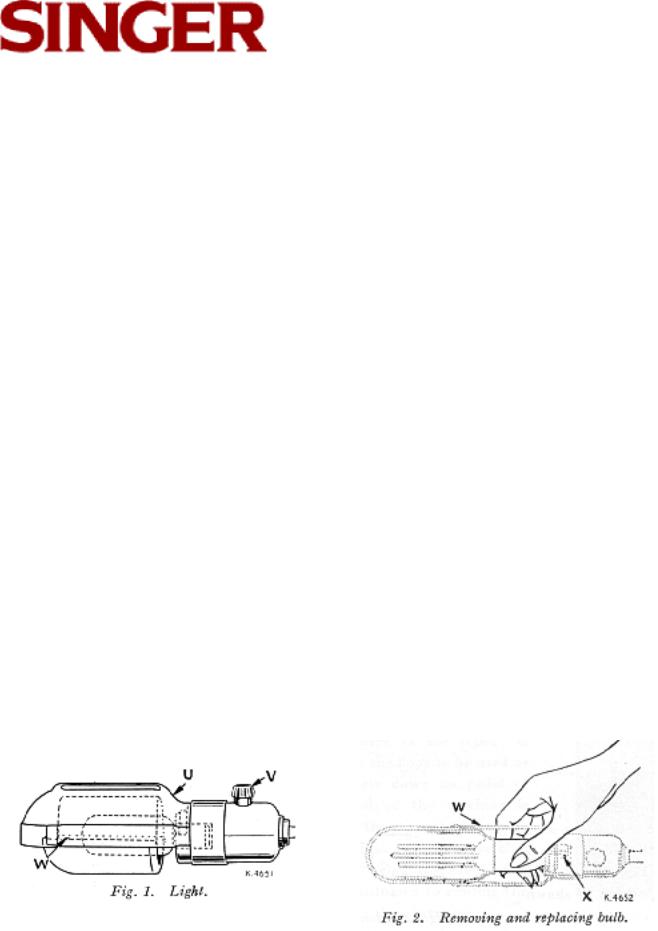
LIGHT
To turn light "on," reach over machine arm and turn switch V, Fig. 1 to right. To extinguish light, turn switch to left.
Page 3
Table of Contents | Previous Page | Next Page
Class 99 & 99K
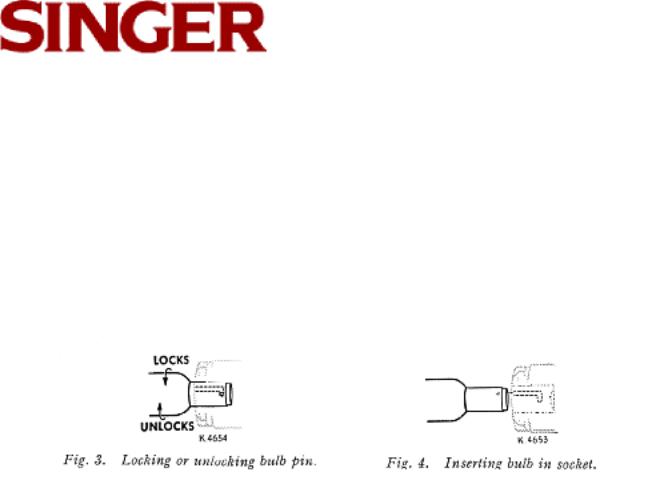
To Remove Bulb
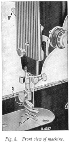
Grasp light socket so that thumb extends over switch V. Press shade with thumb at U. to release shade from two catches, and slide it halfway out of shade holder W. Press bulb into socket and at same time, turn bulb over from machine as far as it will go to unlock pin X (see Figs. 3 and 4). Withdraw the bulb.
To Insert New Bulb
Press bulb into socket and turn it over toward machine until pin X enters notch in socket (see Fig. 3). Return shade to its normal position as shown in Fig. 1.
Page 4
Table of Contents | Previous Page | Next Page
 Class 99 & 99K
If the Machine is Electrically
Operated
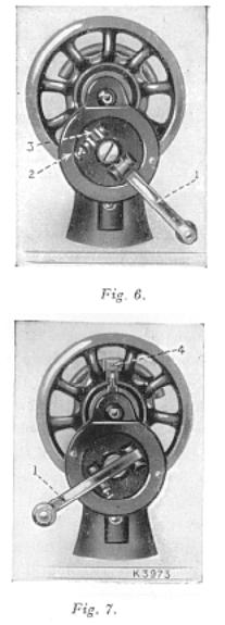
Raise presser foot Q by means of presser bar lifter R to prevent injury to the foot Q and feed T.
Place a piece of material under presser foot and let the foot down upon it. Turn on electric current and, if the combination knee and foot controller is installed as a knee controller, press knee lever to the right. If controller is placed on the floor to be used as a foot controller, press down on pedal of controller. The speed of the machine is controlled entirely by the amount of presser applied to the controller. Operate machine in this way, without being threaded, until you have become accustomed to guiding the material and operating the controller.
Page 5
Table of Contents | Previous Page | Next Page
 Class 99 & 99K
If the Machine is Hand Operated
When the machine is uncovered, the hand attachment will be found to be out of working position as shown in Fig. 6. Pull the small spring stud 2, and turn the handle back until leer 1, enters the socket 3. Press back the hinged finger 4, Fig. 7 between the spokes of the wheel. The machine is now ready for working as shown in Fig. 7.
NOTE. Before replacing the cover on the machine in its case, the lever should be disengaged and the handle placed in the position shown in Fig. 6.
To Operate the Hand Machine
Place a piece of material under the presser foot Q, Fig. 5, and lower the latter by means of the lifter R. Now turn the handle over from you to work the machine, without being threaded, until you are accustomed to guiding the material with the left hand.
Page 6
Table of Contents | Previous Page | Next Page
 Class 99 & 99K
If the Machine is Treadle Operated
Loosen the hand wheel by turning motion screw L, Fig. 16, over toward you, place both feet upon the treadle and turn the hand wheel over toward you, at the same time allowing the feet to move freely and lightly with the motion of the treadle. Continue to do this until a regular and easy movement is acquired and you are able to work the treadle so that you can re-start the machine with the wheel turning toward you.
When familiar with the working movement, tighten the hand wheel by turning the stop motions screw over from you, and place a piece of material under the presser foot Q, Fig. 5. Lower the latter by means of the lifter and again work the machine without being threaded, until you are accustomed to guiding the material.
The belt should be only just tight enough not to slip. If too loose shorten and rejoin.
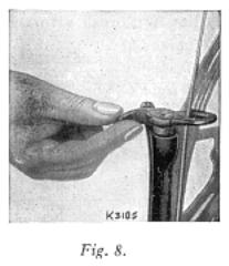
Belt Shifter
This device simplifies throwing off and replacing the belt. To throw off the belt, move the belt shifter to the left (see Fig. 8), working the treadle at the same time. To replace the belt, work the treadle slowly with the hand wheel turning toward you, when a revolutions or tow of the wheel will bring the belt back into its place.
Page 7
Table of Contents | Previous Page | Next Page
 Class 99 & 99K
Protection Against Rust Damage
Lint and fluff, if not removed prior to storage will, during humid periods, absorb and hold moisture, and thus accelerate rust damage to highly polished thread handling and other exposed parts. The extend of rust damage would depend upon the length of time the machine remained in idle storage where there is no ventilation. Sudden drops in temperature till cause moisture to form on parts which, if not protected by a film of oil, would rust and damage while in storage.
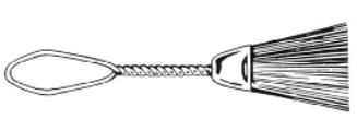
Proper storage care suggests thorough brush-cleaning to remove all traces of lint and fluff, followed by swabbing of all the exposed parts in Figs. 10 and 11 with a lint-free brush saturated with SINGER oil. SINGER lint-free brush may be purchased at your local SINGER dealer.
Page 8
Table of Contents | Previous Page | Next Page
Class 99 & 99K
To Oil the Machine and Stand
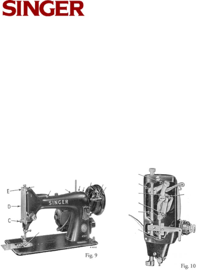
If the machine is used continuously, it should be oiled daily. If moderately used, an occasional oiling is sufficient. Apply one drop of oil at teach of the places indicated by the unlettered arrows in Figs. 9, 10 and 12 and carefully clean the machine to insure smooth and satisfactory performance. Oil holes are provided in the machine for bearings which cannot be directly reached.
Remove face plate D, Fig. 9 by taking out screw C and loosening screw E near the top of the place. Slip plate over screw E. Oil the points indicated in Fig 10 and then replace face plate D.
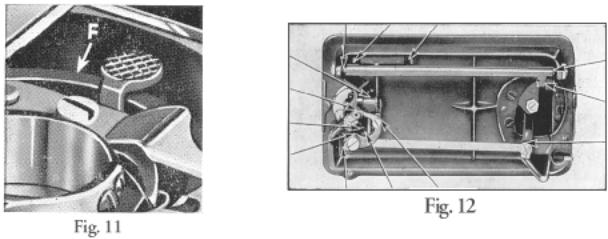
Draw the slide to the left (as shown in Fig. 9) and, after removing the lint and dust which may have accumulated (see instructions on page 24), apply a drop of oil at the place indicated at F, Fig. 11. The slide should then be closed.
Page 9
Table of Contents | Previous Page | Next Page
 Class 99 & 99K
To oil the parts underneath the bed of the machine, turn the machine back on its hinges and apply oil to the oil holes and bearings indicated in
Fig. 12.
To oil the stand, apply a drop of oil to the centers upon which the band wheel and treadle work, and to both ends of the pitman rod connecting the treadle with the band wheel.
After oiling, run the machine rapidly for a few minutes so that the oil may reach the bearings. Neglect to oil the machine will shorten its life and cause you trouble and annoyance.
Always use SINGER oil. Inferior oil clogs the bearings, prevents efficient working, and causes rapid wear of the mechanism.
Page 10
Table of Contents | Previous Page | Next Page
 Class 99 & 99K
Needles and Thread
For perfect stitching, thread should be selected according to fabric to be stitched, and needle must be correct size for thread which must pass freely through eye of the needle.
Page 11
Table of Contents | Previous Page | Next Page
 Class 99 & 99K
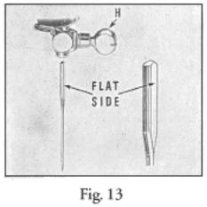
To Set the Needle
Select the correct needle according to the table on page 11. Be sure that the needle is not blunt or bent. Raise the needle bar to its highest position and loosen thumb screw H, Fig. 13 in needle clamp. Push needle with its flat side toward the right up into needle clamp as far as it will go, then tighten the thumb screw H. A screwdriver slot is provided for stronger clamping of needle, required for attachments driven from needle clamp hub.
Page 12
Table of Contents | Previous Page | Next Page
Class 99 & 99K
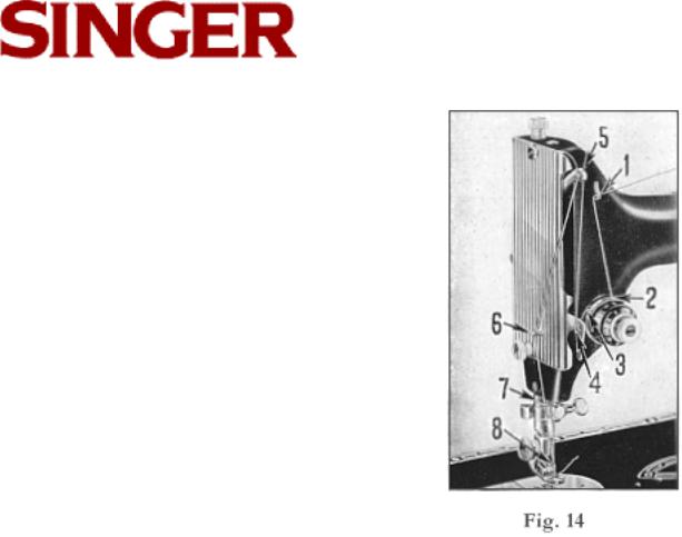
UPPER THREADING
See Fig. 14. Place spool of thread on spool pin. Raise take-up lever 5 to its highest point. Lead thread into thread guide 1, down and from right to left between tension discs 2, into the loop of the take-up spring 3, under the slack thread regulator 4 (not through the eye in the thread regulator), up and from right to left through hole in take-up lever 5, down through guide 6 on the face plate, down through the lower wire guide 7, from left to right through the eye of the needle 8.
Draw about two inches of thread through the eye of the needle with which to begin to sew.
Page 13
Table of Contents | Previous Page | Next Page
Class 99 & 99K
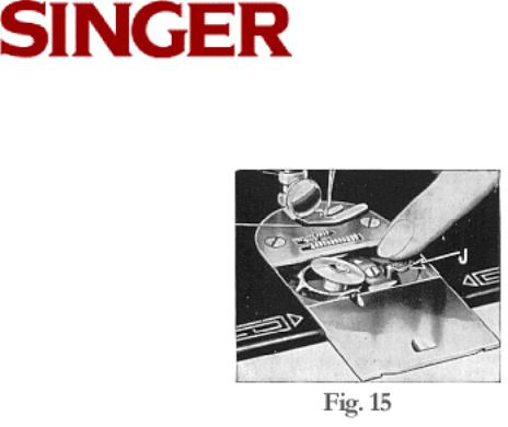
To Remove the Bobbin
Raise needle to its highest point. Draw slide plate to the left. Press bobbin ejector J, Fig. 15, to raise bobbin for easy removal.
Page 14
Table of Contents | Previous Page | Next Page
 Class 99 & 99K
To Wind the Bobbin
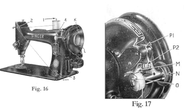
Hold the hand wheel K, Fig. 16, with left hand and with right hand loosen stop motion screw L to disengage stitching mechanism.
Place empty bobbin on bobbin winder spindle, see Fig. 16. Turn bobbin until hole in right side engages pin in spindle. Press bobbin winder downward until latch M, Fig. 17, engages. In this position latch will hold bobbin in place.
Place spool of thread on spool pin 1.
Draw thread through guide 2 on arm of machine. Lead thread from front to rear through lower notch of guide 3.
Thread through O, Fig. 17, in left side of bobbin from inside. The end of the thread must be held by hand until it is broken off by the rotation of the bobbin.
Page 15
Table of Contents | Previous Page | Next Page
 Class 99 & 99K
Fig. 17 shows bobbin winder in position for winding. When sufficient thread has been wound the winder is automatically released.
Remove filled bobbin from bobbin winder spindle and re-tighten stop motion screw L, Fig. 16.
If thread does not wind evenly on bobbin, loosen screw which holds thread guide 3, Fig. 16. Turn guide to left if bobbin winds high on right. Turn guide to left is bobbin winds high on left. When guide is properly centered, thread will wind evenly across bobbin. Tighten guide clamping screw.
If the pressure of bobbin winder pulley N, Fig. 17 against hub of hand wheel is insufficient for winding the bobbin, press down winder until latch M drops down and holds it, then loosen screw P2. With the forefinger push back upper end of slotted plate P1 as far as it will go and at the same time, with the thumb, press winder against ledge of wheel. Then tighten screw P2 securely. Afterwards raise latch to release winder from contact with hand wheel.
Page 16
Table of Contents | Previous Page | Next Page

Class 99 & 99K
To Replace the Bobbin
Hold the bobbin between the thumb and forefinger of the left hand, with the thread leading on top from the right toward the left, as shown in
Fig. 18.
Place bobbin into the bobbin case and draw the thread into the slot 1, Fig. 19 in the bobbin case, as shown.
Draw the thread backward between the bobbin case and the tension spring until it reaches the notch 2, Fig. 20, then pull the thread toward the right as shown in
Fig. 20.
When closing the slide, place thread up through slot 3, Fig. 21 as shown.
FIG. 18 Replacing the Bobbin
FIG. 19 Threading the Bobbin Case
FIG. 20 Bobbin Case Threaded |
FIG. 21 Under Threading Completed |
Page 17
Table of Contents | Previous Page | Next Page
 Loading...