


Singer 4411, 4423, 4443, 4452, 5511 Service Manual
...4411-4423-4432-4443-4452
5511-5523-5532-5554
44S-85SCH
Service Manual
104 73 14-26
2014-02-24
Downloaded from www.Manualslib.com manuals search engine

CONTENTS |
|
1. Namesof principalparts ............................................................................................................. |
2 |
2. Removingmethodsof externalparts |
|
2-1 Sewingtable ........................................................................................................................... |
3 |
2-2 Faceplate ............................................................................................................................... |
3 |
2-3 Basecover .............................................................................................................................. |
3 |
2-4 Free arm base ......................................................................................................................... |
3 |
2-5 Free arm slab ......................................................................................................................... |
4 |
2-6Arm top cover........................................................................................................................ |
4 |
2-7 Backcover .............................................................................................................................. |
5 |
2-8 Frontcover ............................................................................................................................. |
6 |
3. Adjustingmethodsof each part |
|
3-1 Playof arm shaft .................................................................................................................... |
7 |
3-2 Noisytake up leveradjustment .......................................................................................... |
8 |
3-3 Needledrop positionadjustment ......................................................................................... |
8 |
3-4 Heightof presserfoot ............................................................................................................ |
9 |
3-5Needleflowatmaximumzigzagwidth ............................................................................... |
10 |
3-6 Needlecenterpositionadjustment .................................................................................... |
11 |
3-7Needlepositiononzigzag ................................................................................................... |
12 |
3-8Automaticneedlethreaderadjustment ............................................................................. |
13 |
3-9 Adjustmentof feed rock shaftand feed liftingrock cam ................................................. |
14 |
3-10 Heightof needlebar .......................................................................................................... |
15 |
3-11 Timingof needleand hook ............................................................................................... |
16 |
3-12 Distance-needle-hook....................................................................................................... |
17 |
3-13 Playbetweenshuttledrivershaftgear and lowershaftgear ........................................ |
18 |
3-14 Playof shuttledrivershaft ............................................................................................... |
19 |
3-15 Feed-dogheight ................................................................................................................ |
20 |
3-16 Positionof feed-dogin relationto the needleplate(left to right) ................................. |
21 |
3-17 Upperthreadtensionadjustment .................................................................................... |
22 |
3-18 Shuttlehooktensionadjustment ..................................................................................... |
23 |
3-19 Motorbelt tension ............................................................................................................. |
24 |
3-20 Droppointof needle ......................................................................................................... |
25 |
3-21 Forwardand reversestitchingin buttonholesewing |
|
(feedingpitchof reverseand forwardstitchingis not even) ........................................ |
26 |
3-22 Buttonholeupperand lowerstitchingproblem ............................................................. |
27 |
3-23 Bobbinwindingproblem .................................................................................................. |
28 |
 ATTENTION
Be sure to observe the following, as they may well become causes for fire, electric-shock, injuries, and damage to parts.
-Be sure to unplug power source before engaged in disassembly, installation, adjustment.
-In case of installing please pay special care to clamp electrical cords, etc., scars to sheath, mis-circuit, etc.
-Be sure to use regular standard part in replacing.
Downloaded from www.Manualslib.com manuals search engine
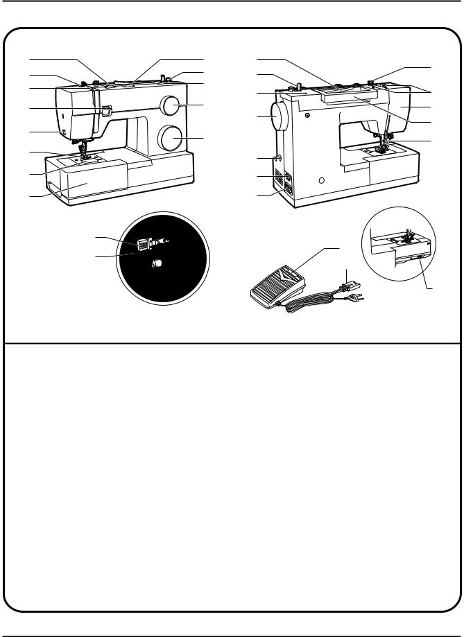
1. Namesof principalparts
1 |
9 |
16 |
23 |
|
2 |
10 |
17 |
||
|
||||
3 |
11 |
18 |
24 |
|
|
||||
|
|
|||
4 |
12 |
19 |
25 |
|
|
|
26 |
||
5 |
|
|
||
13 |
|
27 |
||
|
|
|||
6 |
|
20 |
|
|
|
|
|
||
7 |
|
21 |
|
|
8 |
|
22 |
|
14
29
15
30
28
1. |
Thread tension dial |
16. |
Horizontal spool pin |
2. |
Presser foot pressure adjustment |
17. |
Bobbin winding spindle |
3. |
Thread take-up lever |
18. |
Hole for second spool pin |
4. |
Reverse sewing lever |
19. |
Handwheel |
5. |
Thread cutter |
20. |
Buttonhole stitch balance adjustment slot |
6. |
Presser foot |
21. |
Power and light switch |
7. |
Needle plate cover |
22. |
Main plug socket |
8. |
Removable extension table/ accessory storage |
23. |
Bobbin thread guide |
9. |
Three needle position dial |
24. |
Upper thread guide |
10. |
Bobbin stopper |
25. |
Face plate |
11. |
Stitch width dial |
26. |
Handle |
12. |
Stitch length dial |
27. |
Presser foot lifter |
13. |
Pattern selector dial |
28. |
Drop feed control |
14. |
Automatic threader (not on all model) |
29. |
Foot speed control |
15. |
One step buttonhole lever (not on all model) |
30. |
Power cord |
Downloaded from www.Manualslib.com manuals search engine
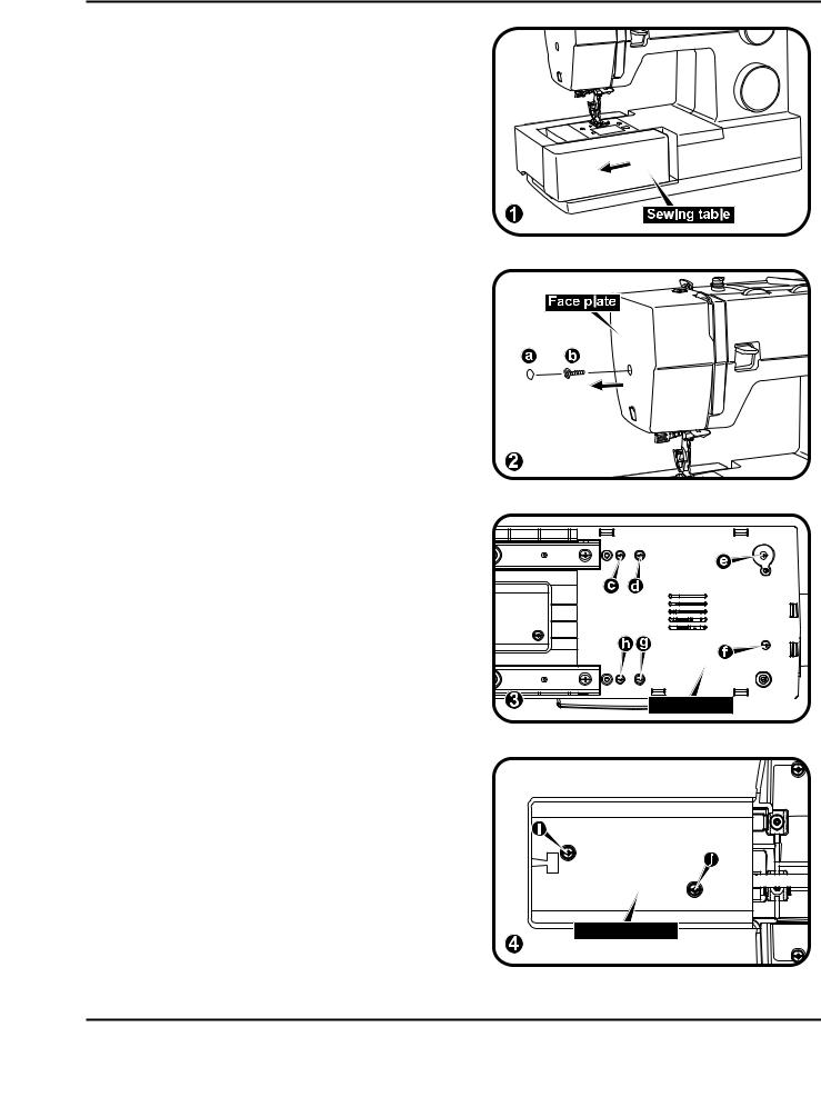
2. Removingmethodsof externalparts
2-1 Sewingtable
Keep the snap-in sewing table horizontal, and pull it in the direction of the arrow. (1)
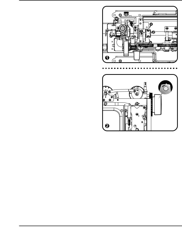
2-2 Faceplate
-Remove the operation cover (a).
-Loosen the screw (b) and remove the face plate. (2)
2-3 Base cover
-Lay down machine.
-Remove the screws (c, d, e, f, g, h). (3)
-Remove the base cover.
2-4 Freearm base
Remove the screws (i, j) and remove the free arm base. (4)
Basecover 
Free arm base |
Downloaded from www.Manualslib.com manuals search engine
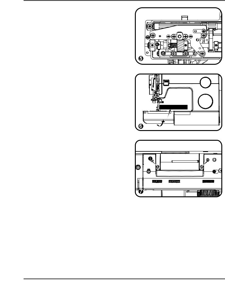
2-5 Free arm slab
- Remove the screw (k). (5)
- Remove the free arm slab. (6)
Free arm slab |
2-6 Armtop cover
Remove the screws (l, m) and remove the arm top cover. (7)
Downloaded from www.Manualslib.com manuals search engine

2-7 Backcover
- Remove the screws (n, o). (9)
- Remove the screw (p). (10)
- Remove the screw (q). (11)
- Remove the back cover. (12)
Downloaded from www.Manualslib.com manuals search engine
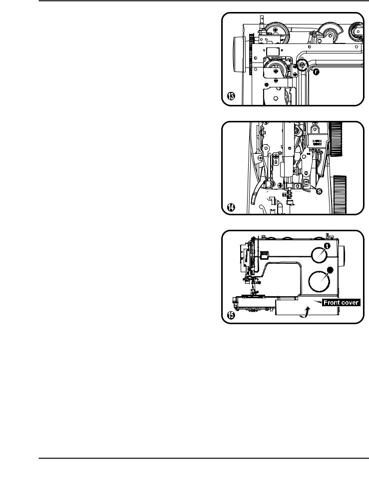
2-8 Frontcover
-Remove the screw (r) which deeply inside the machine. (13)
- Loosen the screw (s) about 3mm. (14)
-Remove the pattern select dial (t, u) and remove front cover following direction of arrow. (15)
u |
Downloaded from www.Manualslib.com manuals search engine
3. Adjustingmethodsof each part
3-1 Playof arm shaft
- Remove the face plate, arm top cover.
- Loosen the screws (a, b) of arm shaft collar
(d). (1)
- Pull the hand wheel to the right. (2)
- Push the arm shaft collar (d) to right tightly against arm shaft bushing (c), and then fasten and secure the screws (a, b). (1)
- Be sure proper distance between arm shaft collar and arm shaft bushing. (1)
- Be sure arm shaft operates smoothly after adjustment.
- Arm shaft collar and arm shaft bushing being too tightly closed might cause insufficient operation of arm shaft.
Downloaded from www.Manualslib.com manuals search engine
3-2 Noisytake up leveradjustment
-Remove the face plate and front cover.
-Turn around hand wheel, check noisy and movement.
-Remove the screw (a), push take up lever support (b) right to proper location, tight the screw (a). (1)
-If adjustment is too tight, it will be difficult to move during turn around hand wheel.
-If adjustment is too loose, it will be made noisy during turn around hand wheel.
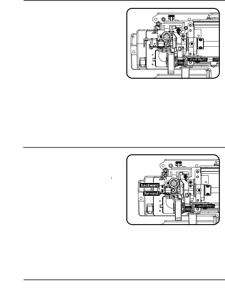
3-3 Needledrop positionadjustment
-Remove the face plate.
-Set the pattern selector dial to " " or "
  ". Turn the stitch width dial to "0".
-Loosen the screw (a) of needle bar supporter. (1)
-Turn needle bar supporter (b) forward / backward to adjust needle. (1)
Backward (↑) to move needle forward Forward (↓) to move needle backward
-Set needle position above center of needle plate and fasten the screw (a). (1)
*The space between needle and the tip of the shuttle hook holder should be 0.05~0.10 mm.
Downloaded from www.Manualslib.com manuals search engine
 Loading...