


Notes for using this parts book
I.This book is applicable to sewing machines which have the plate number as shown on the cover of this book (or correction sheet).
2.If the symbol!._______,I or I000000-0-00I is in the "Parts No." column or the "Assembly No." column, please refer to the different parts list (page 27).
3.The symbol I~Iin the "Parts No." column indicates that the parts is not available for supply. If, however, there is a number in the "Assembly No."column, the parts can be ordered as an assembly. Please, therefore, order by using the assembly number.
4.This book was prepared based on information available in May, 1983.
5.Parts are subject to changes in design without prior notice.
From the library of: Superior Sewing Machine & Supply LLC
CONTENTS
A. |
Machine body (I) .............................................................................. |
|
|
. |
|
A. |
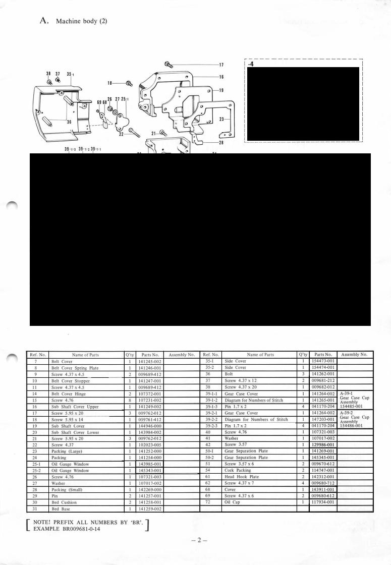
Machine body (2) ............................................................................... |
|
|
|
2 |
B. |
Needle bar and thread take-up mechanism ........................................ |
|
|
3 |
|
C. |
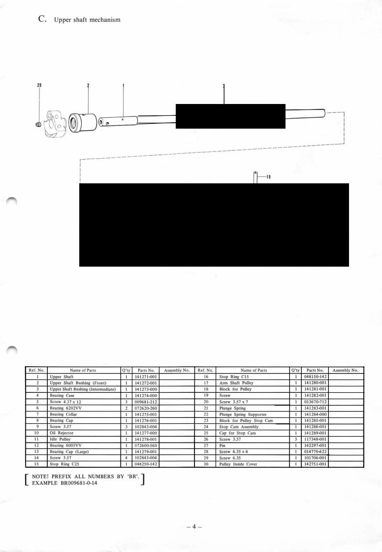
Upper shaft mechanism .... ......... ............................. |
............................ |
|
|
4 |
D. |
Zigzag mechanism (I ) ........................... |
........................... |
.............. |
..... |
5 |
D. |
Zigzag mechanism (2) ............................... |
.......................... |
................ |
|
6 |
E. |
Clutch mechanism ..................... ................... |
...... ................................ |
|
|
7 |
F. |
Power transmitter mechanism .. ...... .............. |
....... .. ............................. |
|
|
8 |
G0 |
Belt shift mechanism ........ ......... .............. |
............ .................... |
........... |
|
8 |
H0 |
Emergency stop mechanism ............................................................... |
|
|
|
9 |
J 0 |
Tension pully mechanism ................................................................... |
|
|
|
9 |
Ko |
Presser foot mechanism ........................... |
........................ |
............... |
.... |
I0 |
Lo |
Feed mechanism (I) ............................. |
........................... |
............... |
.... |
I0 |
Lo |
Feed mechanism (2) ............ ................. |
...... ........................ |
............. |
... |
II |
Lo |
Feed mechanism (3) ........................................................................... |
|
|
|
12 |
M. |
Feed cam mechanism ........................... |
........................... |
............... |
.... |
I3 |
N. |
Thread breakage detector ......................... |
.............................. |
........ |
.... |
13 |
P. |
Cutter mechanism .................................... |
....................... |
................ |
... |
14 |
Q. |
Gimp Guide mechanism ................................................................ |
|
|
~.... |
15 |
Ro |
Tape winder mechanism ..................................................................... |
|
|
|
16 |
S. |
Vertical shaft and Lower shaft mechanism ................ ........................ |
|
|
17 |
|
T. |
Lubrication (I) ................................................................................... |
|
|
|
18 |
T. |
Lubrication (2) ................................................................................... |
|
|
|
19 |
U. |
Threading mechanism (I) .... ..... ..... ..... ... |
...... ....... ... ........ ................ |
..... |
|
20 |
U. |
Threading mechanism (2) .................... |
0.............................................. |
|
|
21 |
V. |
Bobbin winder .......................................... |
....................... |
................... |
|
21 |
W0 Upper Thread Trimmer mechanism (I) |
.............................................. |
|
|
22 |
|
W. |
Upper Thread Trimmer mechanism (2) |
............ ~.............. |
•.................. |
|
23 |
X. |
Lower Thread Trimmer mechanism ................................................... |
|
|
|
24 |
Z. |
Accessories mechanism (I) ................... |
............................ |
.............. |
.... |
25 |
Z. |
Accessories mechanism (2) ..................................... |
............................ |
|
|
26 |
DIFFERENT PARTS LIST ..................................................................... |
|
|
|
27 |
|
GAUGE PARTS LIST ............................................................................. |
|
|
|
35 |
|
MOTOR PULLEY AND BELTS ............................................................. |
|
|
|
37 |
|
INDEX ...................................................................................................... |
|
|
|
38 |
|
From the library of: Superior Sewing Machine & Supply LLC


35
~
Ref. No. |
|
|
|
|
Name of Parts |
Q'ty |
Parts No. |
Assembly No. |
Ref. No. |
|
Name of Parts |
Q'ty |
Parts No. |
|
Assembly No. |
|||||
1 |
|
Speed |
Reduction Gear |
1 |
141309..001 |
|
11-2-3 |
Screw 4.37 |
|
|
1 |
|
104908.002 |
|
|
D-11 Zigzag |
||||
2 |
|
Screw 6.35 x 6 |
|
2 |
014770-622 |
|
11-24 |
Zigzag |
Adjusting |
Ring |
|
1 |
|
|
|
|
||||
|
|
|
|
|
|
|
|
Adjusting Cam |
||||||||||||
3 |
|
Sub |
Shaft |
|
|
1 |
141310..001 |
|
11-2-5 |
Zigzag |
Adjusting |
Ring |
Connector |
1 |
|
|
|
|
Assembly |
|
|
|
|
|
|
|
|
|
|
|
|
|
|
|
|
|
|
|
|
147901..001 |
|
4 |
|
Sub |
Shaft |
Bushing |
(Left) |
1 |
141311..000 |
|
11-3 |
Pin |
|
|
|
1 |
|
141326..001 |
|
|||
|
|
|
|
|
|
|
|
|
||||||||||||
|
|
|
|
|
|
|
|
|
|
|
|
|
|
|
---- |
|
|
|
||
6 |
|
Sub |
Shaft |
Bushing |
(Right) |
1 |
141312..000 |
|
14 |
Zigzag |
Adjusting |
Link |
Shaft |
1 |
|
141328..001 |
|
|
|
|
|
|
|
|
|
|
|
|
---- |
|
|
|
|||||||||
8 |
|
Sub |
Shaft Gear |
|
1 |
141313..001 |
|
15 |
Screw 4.37 x 7 |
|
|
2 |
|
009680.712 |
|
|
|
|||
9 |
|
Screw 6.35 x 6 |
|
2 |
014770-622 |
|
16 |
Zigzag Adjusting |
Link |
|
1 |
|
141329.001 |
|
|
|
||||
10.1 |
|
Collar |
|
|
|
1 |
~ |
D-10 |
17 |
Washer |
|
|
|
1 |
|
102707-002 |
|
|
|
|
|
|
|
|
|
|
|
|
|
|
|
|
|
|
|
|
|
||||
|
|
|
|
|
|
|
|
|
CoUar Assembly |
18 |
Screw |
3.57 x 6 |
|
|
1 |
|
009670-612 |
|
|
|
|
|
|
|
|
|
|
|
|
|
|
|
|
|
|||||||
10.2 |
|
Screw 5.95 |
|
2 |
151604 o01 |
181994..001 |
|
|
|
|
|
|
|
|
|
|
|
|||
|
|
35 |
Screw |
7.94 |
|
|
1 |
|
141344.001 |
|
|
|
||||||||
|
|
|
|
|
|
|
|
|
|
|
|
|
|
|
|
|||||
11-1 |
|
Zigzag Cam |
|
1 |
|
D-11 Zigz~ |
37 |
Nut 7.94 |
|
|
2 |
|
403388..002 |
|
|
|
||||
11-2-1 |
|
Zigzag |
Adjustint Bracket |
1 |
|
Adjusting am |
|
|
|
|
|
|
|
|
|
|
|
|||
|
|
Assembly |
|
|
|
|
|
|
|
|
|
|
|
|||||||
11-2-2 |
|
Zigzag |
Adjusting Shaft |
1 |
---- |
147901.(}01 |
|
|
|
|
|
|
|
|
|
|
|
|||
NOTE! |
PREFIX ALL NUMBERS BY 'BR,.] |
|
|
|
|
|
|
|
|
|
|
|
|
|||||||
[ EXAMPLE BR009681-Q-14
- 5-
From the library of: Superior Sewing Machine & Supply LLC

D. Zigzag mechanism (2)
2 |
23 |
47 |
44 |
··--0
.42
57
34 |
33 |
32 |
49 |
r-------- |
|
, |
1-4 |
~59 |
I |
1 |
I |
|
I |
|
|
I |
|
I |
I |
|
I |
I |
|
I |
I |
|
I |
1 |
|
I |
. ________ ..J
Ref. No. |
Name of Parts |
|
Q'ty |
Parts No. |
Assembly No. |
Ref. No. |
|
Name of Parts |
Q'ty |
|
Parts No. |
Assembly No. |
|||||||||
19 |
|
Pin |
|
|
|
|
1 |
141332-001 |
|
43 |
Zigzag |
Position Changing Lever |
1 |
|
141354..()00 |
|
|||||
20 |
|
Nut 5.95 |
|
|
|
|
1 |
106588..()03 |
|
44 |
Screw |
|
|
|
1 |
|
141355-001 |
|
|
||
21 |
|
Spring |
|
|
|
|
1 |
141333..001 |
|
45 |
Nut 7.94 |
1 |
|
105812..003 |
|
|
|||||
22 |
|
Spring Hook |
|
|
|
|
1 |
141334..001 |
|
46 |
Screw |
|
|
|
1 |
|
141356..001 |
|
|
||
23 |
|
Zigzag Adjusting |
Lever |
|
|
1 |
141335-000 |
|
47 |
Nut 7.94 |
1 |
|
105812.002 |
|
|||||||
|
|
|
|
||||||||||||||||||
24 |
|
Screw |
|
|
|
|
2 |
141336.001 |
|
48 |
Washer |
|
|
|
1 |
|
158449.001 |
|
|
||
|
|
|
|
|
|
|
|
|
|||||||||||||
25 |
|
Pin |
|
|
|
|
2 |
141337.001 |
|
49 |
Stopper |
1 |
|
141357..000 |
|
||||||
26 |
|
Spring |
|
|
|
|
2 |
141338-001 |
|
so |
Screw 5.95 x 6 |
2 |
|
01476o.622 |
|
||||||
27 |
|
Screw |
|
|
|
|
1 |
141339-001 |
|
51 |
Spring |
|
|
|
1 |
|
141358-001 |
|
|
||
28 |
|
Nut 5.95 |
|
|
|
|
1 |
106588-003 |
|
52 |
Spring Hook |
1 |
|
141334-001 |
|
|
|||||
29 |
|
Zigzag Adjusting |
Lever |
Shaft |
1 |
141340.001 |
|
53 |
Zigzag |
Connecting Shaft |
|
|
141359.001 |
|
|
||||||
30 |
|
Screw 5.95 |
|
|
|
|
1 |
013760-612 |
|
54 |
CoUar |
|
|
|
1 |
|
141351.001 |
|
|
||
31 |
|
Zigzag Eccentric |
Shaft |
|
|
1 |
141341.001 |
|
55 |
Screw |
6.35 x 6 |
1 |
|
014770-622 |
|
|
|||||
32 |
|
Zigzag Eccentric |
Shaft |
Link |
1 |
141342.000 |
|
56 |
Bar Tack Connecting Shaft |
1 |
|
141659-001 |
|
|
|||||||
33 |
|
Washer |
|
|
|
|
1 |
149095-001 |
|
51 |
Spring |
|
|
|
1 |
|
141363.001 |
|
|
||
34 |
|
Screw 5.95 x 12 |
|
|
|
|
1 |
009761-212 |
|
58 |
Stop Ring C11 |
1 |
|
048110.142 |
|
|
|||||
36 |
|
Screw 7.94 |
|
|
|
|
1 |
141345-001 |
|
59 |
Stud |
|
|
|
1 |
|
145344-001 |
|
|
||
38 |
|
Zigzag Connecting |
Rod |
|
|
1 |
141346-001 |
|
60 |
Bushing (Right) |
|
|
141716-000 |
|
|
||||||
39 |
|
Screw 4.76 |
|
|
|
|
1 |
100511-003 |
|
61 |
Bushing (Left) |
|
|
141365-000 |
|
|
|||||
40 |
|
Zigzag Connecting |
Lever |
(A) |
1 |
141347-001 |
|
62 |
CoUar |
|
|
|
|
|
141366-001 |
|
|
||||
41 |
|
Screw 4.76 x 14 |
|
|
|
|
1 |
009711412 |
|
64 |
Bushing |
1 |
|
147155-000 |
|
|
|||||
42 |
|
Zigzag Connecting |
Lever |
(B) |
1 |
141348-001 |
|
|
|
|
|
|
|
|
|
|
|
|
|
||
[ |
NOTE! PREFIX ALL NUMBERS BY 'BR'.] |
|
|
EXAMPLE BR009681-0-14 |
- 6 - |
||
|
|||
|
|
From the library of: Superior Sewing Machine & Supply LLC

E. Clutch mechanism
Il-4 -[d |
II |
|
r---------, |
||
I |
|
|
1 |
3-2 |
I |
I |
0 |
I |
Il _________ j I
GJ--60
86-1~ 66·2~
'---~
66-
11
|
|
|
I |
|
|
|
I |
|
|
|
I |
|
|
|
I |
|
--~ |
_....,.I |
|
- .. :::::-..__....___ |
·-~--p~·. |
I |
|
- -· |
·'---m-...L--Y, |
I |
|
'.J
|
Ref. No. |
|
Name of Parts |
Q'ty |
|
Parts No. |
Assembly No. |
|
Ref. No. |
|
|
|
Name of Parts |
|
Q'ty |
Parts No. |
Assembly No. |
||||||||||
|
|
|
|
||||||||||||||||||||||||
3-1 |
|
Stop Cam Segment |
(B) |
1 |
|
141547-001 |
|
|
|
34 |
|
Screw 5.95 x 10 |
|
2 |
009761-012 |
|
|||||||||||
3-2 |
|
Stop Cam Segment |
(B) |
1 |
|
|
145442-o01 |
|
35 |
|
Outch |
Lever Bracket |
|
1 |
141557-002 |
|
|||||||||||
4 |
|
Bolt 5.95 X 14 |
|
|
|
1 |
|
017761-412 |
|
36 |
|
Bolt 8 X 25 |
|
|
3 |
018082-522 |
|
||||||||||
|
s |
Outch Claw (A) |
|
|
|
1 |
|
141548-001 |
|
37 |
|
Outch Lever Shaft |
|
1 |
141558-001 |
|
|||||||||||
|
|
|
|
|
|
|
|
||||||||||||||||||||
6 |
|
Washer |
|
|
|
|
1 |
|
118735-002 |
|
38 |
|
Screw 6.35 x 6 |
|
|
1 |
014770-622 |
|
|||||||||
7 |
|
Bolt 6.35 X 14 |
|
|
|
1 |
|
017781-412 |
|
39 |
|
Clutch |
Return |
Spring |
|
1 |
141559-001 |
|
|||||||||
8 |
|
Emergency Stop Lever Shaft |
1 |
|
141618-001 |
|
40 |
|
Adjusting Plate |
|
|
1 |
115558-002 |
|
|||||||||||||
9 |
|
Stop Lever Spring |
|
|
|
1 |
|
141549-001 |
|
41 |
|
Screw 4.76 |
|
|
1 |
115559-002 |
|
||||||||||
10 |
|
Spring Hook |
|
|
|
2 |
|
141550-001 |
|
42 |
|
Screw 5.95 x 10 |
|
1 |
009761-012 |
|
|||||||||||
11 |
|
Outch |
Lever |
|
|
|
1 |
|
|
146041-D02 |
|
43 |
|
Spring Hook |
|
|
1 |
141334-001 |
|
||||||||
12 |
|
Clutch |
Claw (B) |
|
|
|
1 |
|
141553-001 |
|
44 |
|
Outch Starting Lever |
|
1 |
146955-D04 |
|
||||||||||
13 |
|
Washer |
|
|
|
|
1 |
|
118735-002 |
|
45 |
|
Bolt 7.94 |
|
|
1 |
115585-001 |
|
|||||||||
14 |
|
Bolt 6.35 X 25 |
|
|
|
1 |
|
017782-512 |
|
46 |
|
Nut 7.94 |
|
|
1 |
152997-001 |
|
||||||||||
|
IS |
Clutch Stopper Stud |
1 |
|
115542-001 |
|
48 |
|
Screw 4.76 x 14 |
|
2 |
009711-412 |
|
||||||||||||||
16 |
|
Washer 6 |
|
|
|
1 |
|
025060-332 |
|
|
|
so |
autch |
Starting |
Lever |
Spring |
1 |
141562 001 |
|
||||||||
17 |
|
Screw 5.95 x 12 |
|
|
|
1 |
|
009761-212 |
|
51-1 |
|
autch |
Starting |
Lift Lever |
1 |
---- |
E-51 |
||||||||||
|
|
|
|
|
|
|
|
|
|
|
|
|
|
|
|
|
|
|
|
|
|
|
|
|
|
|
Starting Lift |
18 |
|
Screw |
|
|
|
|
1 |
|
115544-001 |
|
51-2 |
|
Outch |
Starting |
Lever |
Shaft |
1 |
|
|||||||||
|
|
|
|
|
|
|
|
|
Lever Assembly |
||||||||||||||||||
19 |
|
Outch |
Stopper |
|
|
|
1 |
|
115545-001 |
|
51-4 |
|
Screw 6.35 x 6 |
|
|
1 |
014770 622 |
154499-001 |
|||||||||
|
|
|
|
|
|
|
|
|
|
||||||||||||||||||
20 |
|
Screw |
|
|
|
|
1 |
|
115546-001 |
|
53 |
|
Stopper |
|
|
1 |
141564-001 |
|
|||||||||
21 |
|
Washer |
2-S |
|
|
|
1 |
|
028050-240 |
|
54 |
|
Screw 5.95 x 12 |
|
2 |
009761-212 |
|
||||||||||
22 |
|
Nut 4.76 |
|
|
|
1 |
|
021710-202 |
|
56 |
|
Brake |
Lever Assembly |
|
1 |
142755-001 |
|
||||||||||
23 |
|
Stopper Bar |
|
|
|
1 |
|
141554-001 |
|
58 |
|
Screw 7.14 |
|
|
1 |
141953-001 |
|
||||||||||
24 |
|
Spring (C) |
|
|
|
1 |
|
147639-001 |
|
59 |
|
Brake |
Lever Pin |
|
1 |
142214.()01 |
|
||||||||||
25 |
|
Spring Felt |
|
|
|
1 |
|
115550.001 |
|
60 |
|
Screw 5.95 |
|
|
1 |
151604-002 |
|
||||||||||
26 |
|
Spring (B) |
|
|
|
1 |
|
|
11SSS1-001 |
|
61 |
|
Washer |
|
|
|
1 |
107153-002 |
|
||||||||
27 |
|
Washer |
10 |
|
|
|
1 |
|
025100-132 |
|
62 |
|
Stop Ring E7 |
|
|
1 |
048070-342 |
|
|||||||||
|
28 |
|
Nut 9.52 |
|
|
|
1 |
|
021860-202 |
|
63 |
|
Brake Spring |
|
|
1 |
142771.001 |
|
|||||||||
|
29 |
|
Bar Clamp |
|
|
|
1 |
|
115552-001 |
|
64 |
|
Spring |
Hook |
|
|
1 |
141334.()01 |
|
||||||||
|
30 |
|
Washer |
10 |
|
|
|
1 |
|
025100-132 |
|
65 |
|
Nut 9.52 |
|
|
1 |
100075 004 |
|
||||||||
|
31 |
|
Stop Ring C10 |
|
|
|
1 |
|
048100-142 |
|
66-1 |
|
Stop Lever |
|
|
1 |
|
E-66 |
|||||||||
|
|
|
|
|
|
|
|
|
|
|
|||||||||||||||||
|
|
|
|
|
|
|
|
|
|
|
|
|
|
|
|
|
|
|
|
|
|
|
|
|
|
|
Stop Lever |
|
32 |
|
Clutch |
Lever Pin |
|
|
|
1 |
|
141555.001 |
|
66-2 |
|
Bushing |
|
|
1 |
142372.()00---- |
|||||||||
|
|
|
|
|
|
|
|
|
|
Assembly |
|||||||||||||||||
|
33 |
|
Belt Shifter |
|
|
|
1 |
|
141556-101 |
|
66-3 |
|
Bushing |
|
|
1 |
142373-000 |
181708-001 |
|||||||||
NOTE! PREFIX ALL NUMBERS BY 'BR'.] [ EXAMPLE BR009681-0-14
-7-
From the library of: Superior Sewing Machine & Supply LLC
F. Power transmitter mechanism |
G. Belt shift mechanism |
Ref. No. |
|
Name of Parts |
Q'ty |
Parts No. |
Assembly No. |
||||
1 |
|
Transmitter |
Base |
1 |
|
147222..002 |
|
|
|
|
|
|
|||||||
2 |
|
Bolt 8 x 25 |
|
|
3 |
|
---- |
|
|
|
|
|
|
018082 522 |
|
|
|||
3- 1 |
|
Transmitter |
Shaft |
1 |
|
|
|
|
|
3- 2 |
|
Slow Speed Pulley |
1 |
|
|
|
|
||
3- 3 |
|
Bearing 6007VV |
2 |
|
|
|
|
||
3- 4 |
|
Bearing Coller |
1 |
|
|
|
|
||
3- 5 |
|
Bearing Cap |
|
|
1 |
|
|
|
|
3-10 |
|
Bearing 6004VV |
2 |
|
---- |
|
F-3 |
||
3- 6 |
|
Screw 3.18 x 8 |
4 |
|
003660 812 |
|
|||
3- 7 |
|
Pulley |
|
|
1 |
|
---- |
|
Transmitter |
|
|
Pulley |
|
|
1 |
|
|
|
Assembly |
3- 8 |
|
|
|
|
|
|
141566{101 |
||
3- 9 |
|
Screw 4.76 x 14 |
2 |
|
---- |
|
|
||
|
|
009711 412 |
|
|
|||||
3-11 |
|
Bearing Cap |
|
|
2 |
|
|
|
|
3-12 |
|
Screw 3.18 x 8 |
8 |
|
003660 812 |
|
|
||
3-13 |
|
Stop Ring C20 |
1 |
|
048200-142 |
|
|
||
4 |
|
Screw 6.35 x 10 |
2 |
|
013781..012 |
|
|
||
5 |
|
Oil Cap |
|
|
1 |
|
111937..001 |
|
|
NOTE! PREFIX ALL NUMBERS BY 'BR'.] [ EXAMPLE BR009681·D-14
18 19
Ref. No. |
|
Name of Parts |
Q'ty |
Parts No. |
Assembly No. |
||||
1 |
Belt |
Shifter |
Bar |
|
'1 |
|
141574..001 |
|
|
2 |
Belt |
Shift Lever |
1 |
|
141575.001 |
|
|
||
4 |
Bushing |
|
2 |
|
142373.000 |
|
|
||
5 |
Bolt |
7.94 |
|
1 |
|
115585.001 |
|
|
|
6 |
Nut |
7.94 |
|
1 |
|
152997.001 |
|
|
|
7 |
Roller with Roller Stud Assembly |
1 |
|
141576..001 |
|
|
|||
8 |
Nut 5.56 |
|
1 |
|
021750.102 |
|
|
||
9 |
Belt |
Shift Lever Pin |
1 |
|
141579..001 |
|
|
||
10 |
Screw 6.35 x 6 |
1 |
|
01477o-622 |
|
||||
11 |
Stopper Plate |
1 |
|
141580{101 |
|
|
|||
12 |
Screw 4.37 x 8 |
2 |
|
009680.812 |
|
|
|||
13 |
Spring |
|
1 |
|
141581.001 |
|
|
||
14 |
Spring Hook |
|
1 |
|
141472.002 |
|
|
||
15 |
Belt Shifter Cam |
1 |
|
141582.001 |
|
|
|||
16 |
Screw 6.35 |
|
1 |
|
141583.001 |
|
|
||
17-1 |
Belt |
Shifter |
Bracket |
1 |
|
~ |
G-17 Belt |
||
|
Shifter Bracket |
||||||||
|
|
|
|
|
|
|
|||
17-2 |
Slide |
Block |
|
1 |
|
141586.001 |
|
Assembly |
|
|
|
|
141584-001 |
||||||
18 |
Belt |
Shifter |
Guide |
2 |
|
141588..001 |
|
|
|
19 |
Screw 4.37 x 8 |
4 |
|
009680-812 |
|
|
|||
20 |
Belt |
Shifter |
|
1 |
|
141589.001 |
|
|
|
21 |
Screw 4.76 x 10 |
2 |
|
009711..()12 |
|
|
|||
22 |
Stop |
Ring E7 |
1 |
|
048070.342 |
|
|
||
23 |
Spring |
|
1 |
|
145931.001 |
|
|
||
- 8 -
From the library of: Superior Sewing Machine & Supply LLC

H. Emergency stop mechanism |
J. Tension pully mechanism |
1-7 |
1- |
4 1 |
-s 1- |
& |
1-a |
Ref. No. |
Name of Parts |
Q'ty |
|
Parts No. |
Assembly No. |
|
|
|
Ref. No. |
|
|
|
Name of Parts |
|
|
|
|
Q'ty |
|
|
Parts No. |
Assembly No. |
||||||||||
1 |
Emergency |
Stop |
Lever |
1 |
|
|
141698.001 |
|
|
|
|
1- 1 |
|
|
|
Tension |
Pulley |
|
|
|
|
|
|
1 |
|
|
141622..()00 |
|
|
|
||
2 |
Screw 4.37 |
|
|
2 |
|
|
107407.003 |
|
|
|
|
1- 2 |
|
|
|
Bearing 6000DD |
|
|
|
|
2 |
|
|
072600..()40 |
|
|
|
|||||
3 |
Spring |
|
|
1 |
|
|
141699.001 |
|
|
|
|
1- 3 |
|
|
|
Collar |
|
|
|
|
|
|
|
1 |
|
|
142342.000 |
|
|
|
||
4 |
Emergency |
Stop |
Supporter |
1 |
|
|
141700.001 |
|
|
|
|
1- 4 |
|
|
|
Cap Plate |
|
|
|
|
|
|
1 |
|
|
141316.001 |
|
|
|
|||
5 |
Washer |
|
|
1 |
|
|
141701.001 |
|
|
|
|
1- 5 |
|
|
|
Screw 3.18 |
|
|
|
|
|
|
4 |
|
|
110185.002 |
|
|
|
|||
6 |
Screw |
|
|
1 |
|
|
141702.001 |
|
|
|
|
1- 6 |
|
|
|
Tension |
Pulley |
Shaft |
|
|
|
|
1 |
|
|
141623.001 |
|
|
|
|||
7 |
Retainer Plate |
|
1 |
|
|
141703.001 |
|
|
|
|
1- 7 |
|
|
|
Stop Ring E9 |
|
|
|
|
|
|
1 |
|
|
048090-342 |
|
|
|
||||
8 |
Bolt 4.37 X 10 |
|
2 |
|
|
017681.012 |
|
|
|
|
1- 8 |
|
|
|
Tension |
Pulley |
Arm |
|
|
|
|
1 |
|
|
141624.001 |
|
|
|
||||
9 |
Emergency |
Stop Joint |
1 |
|
|
141704.001 |
|
|
|
|
1- 9 |
|
|
|
Tension |
Pulley |
Indicator |
|
|
|
|
1 |
|
|
141625..()01 |
|
J-1 |
|||||
10 |
Washer 4.37 |
|
2 |
|
|
02568Q-232 |
|
|
|
|
1-10 |
|
|
|
Screw 3.57 x 6 |
|
|
|
|
|
|
2 |
|
|
|
|
|
|
||||
|
|
|
|
|
|
|
|
|
|
|
|
|
|
|
|
|
|
|
00967Q-612 |
Tension Pulley |
||||||||||||
NOTE! PR~TX ALL mfMBERS BY •BR'. ] |
|
|
|
|
1-11 |
|
|
|
Tension |
Pulley |
Lever |
|
|
|
|
1 |
|
|
143917.001 |
|
Assembly |
|||||||||||
|
|
|
|
|
|
|
|
|
|
|
|
|
|
|
|
|
|
|
|
|
|
|
141621.001 |
|
||||||||
|
|
|
|
1-12 |
|
|
|
Washer |
|
|
|
|
|
|
|
1 |
|
|
141627.001 |
|
|
|||||||||||
|
|
|
|
|
|
|
|
|
|
|
|
|
|
|
|
|
|
|
||||||||||||||
[ EXAMPLE B~~~4-· |
|
|
|
|
|
|
|
|
1-13 |
|
|
|
Screw 3.57 x 12 |
|
|
|
|
2 |
|
|
007671-212 |
|
|
|
||||||||
|
|
|
|
|
|
|
|
|
|
|
|
1-14 |
|
|
|
Tension |
Pulley Pawl |
~ |
|
1 |
|
|
141628-001 |
|
|
|
||||||
|
|
|
|
|
|
|
|
|
|
|
|
|
|
|
|
|
|
|
|
|
|
|
|
|
|
|
|
|
|
|
|
|
|
|
|
|
|
|
|
|
|
|
|
|
1-15 |
|
|
|
Tension |
Pulley |
Pawl Shaft |
|
|
|
|
1 |
|
|
141629..()01 |
|
|
|
|||
|
|
|
|
|
|
|
|
|
|
|
|
1-16 |
|
|
|
Spring |
|
|
|
|
|
|
|
1 |
|
|
14163().()01 |
|
|
|
||
|
|
|
|
|
|
|
|
|
|
|
|
1-17 |
|
|
|
Collar |
|
|
|
|
|
|
|
1 |
|
|
141631..()01 |
|
|
|
||
|
|
|
|
|
|
|
|
|
|
|
|
1-18 |
|
|
|
Stop Ring E3 |
|
|
|
|
|
|
2 |
|
|
|
04803Q-342 |
|
|
|||
|
|
|
|
|
|
|
|
|
|
|
|
|
|
|
|
|
||||||||||||||||
|
|
|
|
|
|
|
|
|
|
|
|
1-19 |
|
|
|
Spring Pin AW2.S |
|
|
|
|
2 |
|
|
|
04725o-842 |
|
|
|||||
|
|
|
|
|
|
|
|
|
|
|
|
1-20 |
|
|
|
Tension |
Lever |
|
|
|
|
|
|
1 |
|
|
143914.001 |
|
|
|
||
|
|
|
|
|
|
|
|
|
|
|
|
2 |
|
|
|
Screw 7.94 |
|
|
|
|
|
|
1 |
|
|
141632.001 |
|
|
|
|||
|
|
|
|
|
|
|
|
|
|
|
|
3 |
|
|
|
Tension |
Pulley |
Ratchet |
|
|
|
|
1 |
|
|
141633..()01 |
|
|
|
|||
|
|
|
|
|
|
|
|
|
|
|
|
4 |
|
|
|
·screw 4.37 x 8 |
|
|
|
|
|
|
3 |
|
|
009680-812 |
|
|
|
|||
-9-
From the library of: Superior Sewing Machine & Supply LLC

K. Presser foot mechanism |
L. Feed mechanism (I) |
5 --- (§>
r------------,
1-4
I17·2-J~
1 7-N~~::;:~F-,~~
I l17-N-EJID
7·2-4----=:toy/~
I 7·2-2---~~~
I
I
I
I
L ___________ ...J
Ref. No. |
|
|
Name of Parts |
Q'ty |
Parts No. |
|
Assembly No. |
|||||
1 |
|
Presser |
Bar |
|
|
|
1 |
|
141449.001 |
|
|
|
2 |
|
Presser |
Bar |
Bracket |
1 |
|
1414SQ-001 |
|
|
|
||
3 |
|
Screw 6.3S x 6 |
|
1 |
|
014170-622 |
|
|
|
|||
4 |
|
Presser |
Bar |
Spring |
(Large) |
1 |
|
1414S1.()01 |
|
|
|
|
s |
|
Washer |
|
|
|
|
1 |
|
100281.()01 |
|
|
|
6 |
|
Screw |
|
|
S |
|
1 |
|
---- |
|
1414SS-Q01 |
|
|
|
|
|
|
|
1414S4.()01 |
|
|
|
|||
7-1-1 |
|
Presser |
Bar |
Roller |
Bracket |
1 |
|
|
|
|
|
|
7-1-2 |
|
Roller |
7 x 17 |
|
|
1 |
|
1S6879.()01 |
|
K-7-1 |
|
|
7-1-3 |
|
Roller |
Stud |
|
|
1 |
|
|
|
Presser |
Bar |
|
7-1-4 |
|
Stop Ring |
E6 |
|
1 |
|
048060 342 |
|
Roller Bracket |
|||
7-1-S |
|
Screw 4.37 x |
|
|
1 |
|
100366.()02 |
|
Assembly |
|||
|
|
|
|
|
|
|
||||||
7-1-6 |
|
Washer |
3.5 |
|
|
|
1 |
|
--- |
|
K-7-2 |
|
|
|
|
|
|
02S3SQ 332 |
|
|
|
||||
7-1-7 |
|
Screw |
3.S7 x S |
|
1 |
|
00167Q-S12 |
|
|
|
||
7-2-1 |
|
Presser |
Bar |
Roller |
Bracket |
1 |
|
|
|
|
|
|
7-2-2 |
|
Roller |
7 x 14 |
|
|
1 |
|
1S6880.()01 |
|
|
|
|
7-2-3 |
|
Roller |
Stud |
|
|
1 |
|
|
|
Presser |
Bar |
|
7-2-4 |
|
Stop Ring |
E6 |
|
1 |
|
048060 342 |
|
Roller |
Bracker |
||
7-2-S |
|
Screw 4.37 x S |
|
1 |
|
100366.002 |
|
Assembly |
||||
|
|
|
|
|
|
|
|
|
--- |
|
14S377-001 |
|
7-2-6 |
|
Washer |
3.S |
|
|
|
1 |
|
02S3S0-332 |
|
||
7-2-7 |
|
Screw |
3.S7 x S |
|
1 |
|
001670·S12 |
|
|
|
||
8 |
|
Screw 4.37 x 10 |
|
1 |
|
009681.()12 |
|
|
|
|||
[ |
NOTE! PREFIX ALL NUMBERS BY 'BR'. ] |
||
EXAMPLE |
BR009681-0-14 |
||
|
|||
r=2---------------~
I
I
47-1~ |
I |
|
• _,_47-a-1·7 l |
|
I |
|
|||
|
I |
|
|
|
|
I |
|
47+1·3--ft ~47-a-r-s 47-a-1-1 |
|
|
I |
|
I |
47-1-J-4~ |
|
I |
|
||
47·3·5------i |
|
47-•-5-jl' |
47-e-t-9~ |
|
I |
|
|||
|
~ |
47-1-1·5-' |
||
47·3-4~ |
·I |
|
||
47·3-3~ |
I |
|
47-1-4~ |
|
|
47-1·3~ .-47-17 |
|||
I |
|
|||
|
|
|||
47-3-1 ~ % |
I |
|
~ ~47-a-s |
|
I |
|
47-1·2~---' |
||
|
I |
|
47-1-1·1~ |
|
|
II |
|
||
|
I |
|
|
|
_______________J |
|
|
|
|
r~J-------------- |
~ ~ |
--~------------- |
~ |
|
|
I |
-5 |
|
|
|
|
|
|
|
rr=ror:l3 |
I |
|
|
|
I |
|
|
|
|
I |
|
|
|
|
|
I |
|
|
|
47-&·2----r ~ |
I |
|
|
|
|
I |
|
|
|
47-&-5-.f&l |
I |
|
|
|
I |
|
|
|
|
47-&-c~ |
I |
|
|
|
47-&-3-----l\ |
I |
|
|
|
I |
|
|
|
|
|
|
|
|
|
|
I |
|
|
|
|
I |
|
|
|
|
I |
|
|
|
|
I |
|
|
|
|
I |
|
|
|
I |
I |
|
|
|
I |
|
|
|
|
L----------------.J |
|
|
|
|
Ref. No. |
|
|
Name of Parts |
Q'ty |
|
Parts No. |
Assembly No. |
|||||||||
47- |
3-1 |
|
Upper Clamping |
Foot |
Rubber |
1 |
144498.()01 |
L-47-3 |
||||||||
47- 3-2 |
|
Upper |
Clamping |
Foot Supporter |
1 |
|
|
|
Upper Clamping |
|||||||
|
|
|
|
|
|
|
|
|
|
|
|
|
144496.()01 |
Rubber |
||
47- |
3-3 |
|
Pin |
|
|
|
|
|
|
|
|
2 |
||||
47- 3-4 |
|
Spring |
|
|
|
|
|
|
|
|
2 |
107401.()01 |
Foot Assembly |
|||
|
|
|
|
|
|
|
|
|
|
|
|
|
--- |
1S0764-o01 |
||
47- 3-S |
Screw |
1.98 |
|
|
|
|
|
2 |
107404-001 |
|||||||
|
|
|
|
|
|
|||||||||||
47- 6-1 |
|
Upper Clamping Foot Rubber |
1 |
14463Q 001 |
|
|||||||||||
47- 6-2 |
|
Upper Clamping |
Foot |
Supporter |
1 |
|
|
|
L-47-6 |
|||||||
47- 6-3 |
|
Pin |
|
|
|
|
|
|
|
|
2 |
----144496 001 |
Upper Clamping |
|||
|
|
|
|
|
|
|
|
|
Foot Assembly |
|||||||
|
|
|
|
|
|
|
|
|
|
|
||||||
47- 6-4 |
|
Rubber .Foot Presser |
Plate Spring |
2 |
144707..()01 |
|||||||||||
|
1S0768-001 |
|||||||||||||||
47- |
6-S |
Screw |
1.98 |
|
|
|
|
|
2 |
107404-001 |
|
|||||
47- |
8-1-1 |
|
Upper Clamping Foot (2S-4) |
1 |
---- |
|
||||||||||
|
14S362.()01 |
|
||||||||||||||
47- |
8-1-2 |
Upper Clamping |
Foot |
Supporter |
1 |
|
|
|
|
|||||||
|
|
|
|
|||||||||||||
47- |
8-1-3 |
|
Pin |
|
|
|
|
|
|
|
|
1 |
144496.()01 |
|
||
47- |
8-1-4 |
|
Spring |
|
|
|
|
|
|
|
|
1 |
107401-001 |
|
||
47· |
8-1-S |
Spring |
Plate |
|
|
|
|
|
1 |
14S36S-001 |
|
|||||
47- |
8-1-6 |
|
Thread Presser |
|
|
|
|
|
1 |
14S366-001 |
L-47·8 |
|||||
47- |
8-1-7 |
|
|
|
|
|
|
|
|
|
|
|
|
|
|
|
|
Screw |
2.38 |
|
|
|
|
|
2 |
11110S.()01 |
|||||||
|
|
|
|
|
|
Upper Clamping |
||||||||||
|
|
|
|
|
|
|
|
|
|
|
|
|
|
|
|
|
47- |
8-1·8 |
|
Screw |
1.98 |
|
|
|
|
|
1 |
|
107404.()01 |
Foot Assembly, |
|||
47- 8-1-9 |
|
Pin |
|
|
|
|
|
|
|
|
1 |
146034..()01 |
2Smm |
|||
47- 8-2 |
|
Gimp |
Fixed Knife |
|
|
|
1 |
14S367-001 |
150170.()01 |
|||||||
|
|
|
|
|
||||||||||||
47· 8-3 |
|
Gimp Trimming |
Knife |
1 |
14S731.()01 |
|
||||||||||
47- 8-4 |
|
Gimp Trimming Crank |
1 |
14S369-001 |
|
|||||||||||
47- 8-S |
Screw |
3.S7 |
|
|
|
|
|
1 |
14S37Q-001 |
|
||||||
47- 8-6 |
|
Gimp |
Detach Lever |
|
|
|
1 |
14S373-001 |
|
|||||||
47- |
8-7 |
|
Screw |
2.38 |
|
|
|
|
|
1 |
14S371.001 |
|
||||
47-12-1 |
|
Upper Clamping |
Foot |
SO |
1 |
---- |
|
|||||||||
|
14723Q 001 |
L-47-12 |
||||||||||||||
47-12-2 |
|
Upper Clamping Foot Supporter SO |
1 |
|
|
|
Upper Clamping |
|||||||||
|
|
|
Pin |
|
|
|
|
|
|
|
|
|
|
|
|
|
47-12-3 |
|
|
|
|
|
|
|
|
|
2 |
144496 001 |
Foot Assembly, |
||||
|
|
|
|
|
|
|
|
|
|
|
|
|
so |
|||
47-12-4 |
|
Spring |
|
|
|
|
|
|
|
|
2 |
107401-001 |
||||
|
|
|
|
|
|
|
|
|
|
|
|
|
|
|
|
1S0766-001 |
47-12-5 |
|
Screw |
1.98 |
|
|
|
|
|
2 |
107404-001 |
||||||
|
|
|
|
|
|
|
||||||||||
-10-
From the library of: Superior Sewing Machine & Supply LLC

L. Feed mechanism (2)
....
'-----,4·•·•
|
Ref. No. |
|
|
|
Name of Parts |
Q'ty |
Parts No. |
|
Assembly No. |
|
Ref. No. |
|
|
|
Name of Parts |
|
Q'ty |
|
Parts No. |
|
Assembly No. |
|||||||||||||||||
|
1-1 |
|
|
Feed Cam Shaft |
Bracket |
1 |
|
---- |
|
L-1 |
26-1 |
|
|
|
Feed |
Lever |
(B) |
|
1 |
|
141422..001 |
|
|
|
|
|
|
|||||||||||
|
|
|
|
|
|
|
|
|
|
|
|
|
|
|
||||||||||||||||||||||||
|
|
|
|
|
|
|
|
|
|
|
|
|
|
|
|
|
||||||||||||||||||||||
|
1-2 |
|
|
Feed Shaft |
|
1 |
|
|
|
Feed Cam |
27 |
|
|
|
Screw 5.95 x 10 |
|
2 |
|
009761..012 |
|
|
|
|
|
||||||||||||||
|
1-3 |
|
|
Washer |
12.70 |
|
1 |
|
025900.232 |
|
Shaft Assembly |
28 |
|
|
|
Feed |
Lever |
Shaft |
|
1 |
|
147945..001 |
|
|
|
|
|
|
||||||||||
|
1-4 |
|
|
Nut |
12.70 |
|
1 |
|
021910.302 |
|
141401.001 |
|
29 |
|
|
|
Stop |
Ring |
ES |
|
1 |
|
048050.342 |
|
|
|
|
|
||||||||||
|
2 |
|
|
Screw 5.95 x 12 |
|
3 |
|
009761-212 |
|
|
|
|
31-1 |
|
|
|
Wing Nut 5.95 |
|
1 |
|
118262..002 |
|
|
|
|
|
||||||||||||
|
3 |
|
|
Bushing |
|
1 |
|
141404..000 |
|
|
|
|
32 |
|
|
|
Stud |
|
|
|
|
|
|
1 |
|
141426..001 |
|
|
|
|
|
|||||||
|
4-1- 1 |
|
|
Feed Cam |
|
1 |
|
---- |
|
|
|
|
33 |
|
|
|
Screw 6.35 x 6 |
|
1 |
|
|
01477o-622 |
|
|
|
|
||||||||||||
|
|
|
|
|
|
|
|
|
|
|
|
|
|
|
|
|
|
|||||||||||||||||||||
|
|
|
|
|
|
|
|
|
|
|
|
|
|
|
|
|
|
|
|
|||||||||||||||||||
|
4-1- 2 |
|
|
Thread |
Release Cam Segment |
1 |
|
143943..001 |
|
|
|
|
34-1 |
|
|
|
Feed |
Guide |
Shaft Bracket |
|
1 |
|
141427..002 |
|
|
|
|
|
||||||||||
|
4-1- 3 |
|
|
Screw 4.37 |
|
2 |
|
107407..003 |
|
|
|
|
35 |
|
|
|
Bushing |
|
|
|
|
|
2 |
|
142374..000 |
|
|
|
|
|
||||||||
|
4-1- 4 |
Thread Tension Release Segment (B) |
1 |
|
143944-001 |
|
|
|
|
36 |
|
|
|
Bolt 8 x 14 |
|
|
|
|
|
3 |
|
018081-422 |
|
|
|
|
|
|||||||||||
|
4-1- 5 |
|
|
Screw 4.37 x 12 |
|
2 |
|
009681-212 |
|
L-4·1 |
37 |
|
|
|
Feed Guide |
Shaft |
|
1 |
|
141429..001 |
|
|
|
|
|
|
||||||||||||
|
4-1- 6 |
|
|
Bar Tack Cam Segment |
2 |
|
141445..001 |
|
Feed Cam |
38 |
|
|
|
Feed |
Arm |
Bracket |
|
1 |
|
141430.002 |
|
|
|
|
|
|||||||||||||
|
|
|
|
|
Assembly |
|
|
|
|
|
|
|
|
|
|
|||||||||||||||||||||||
|
4-1- 7 |
|
|
Screw 4.37 x 12 |
|
4 |
|
009681-212 |
|
39 |
|
|
|
Screw 6.35 x 6 |
|
1 |
|
014770-622 |
|
|
|
|
|
|||||||||||||||
|
|
|
|
|
|
143942..001 |
|
|
|
|
|
|
|
|
|
|
|
|||||||||||||||||||||
|
4-1- 8 |
|
|
Stop |
Cam Segment (Large) |
1 |
|
141446..001 |
|
|
|
|
40 |
|
|
|
Stud |
|
|
|
|
|
|
1 |
|
141431..001 |
|
|
|
|
|
|
||||||
|
4-1- 9 |
|
|
Screw 4.37 x 10 |
|
2 |
|
009681-012 |
|
|
|
|
41 |
|
|
|
Feed |
Bar Guide Block |
|
1 |
|
118215..001 |
|
|
|
|
|
|
||||||||||
|
4-1-10 |
|
|
Cutter Segment |
|
1 |
|
141448-001 |
|
|
|
|
42 |
|
|
|
|
Stop |
Ring |
E4 |
|
1 |
|
048040-342 |
|
|
|
|
|
|||||||||
|
4-1-11 |
|
|
Screw 4.37 |
|
2 |
|
107407-003 |
|
|
|
|
43·1 |
|
|
|
Length Feed |
Arm |
|
1 |
|
141433-002 |
|
|
|
|
|
|||||||||||
|
5 |
|
|
Bushing |
|
1 |
|
142375-000 |
|
|
|
|
44-1 |
|
|
|
Feed |
Arm |
Shaft |
|
1 |
|
141434..001 |
|
|
|
|
|
|
|||||||||
|
|
|
|
|
|
|
|
|
|
|
|
|
|
|
|
|
||||||||||||||||||||||
|
6 |
|
|
Washer |
|
|
1 |
|
141400001 |
|
|
|
|
45 |
|
|
|
Screw 6.35 x 6 |
|
1 |
|
---- |
|
|
|
|
|
|
|
|||||||||
|
|
|
|
|
|
|
|
|
|
|
|
|
|
|
014770 622 |
|
|
|
|
|
||||||||||||||||||
|
7 |
|
|
Screw 5.95 |
|
1 |
|
141408-001 |
|
|
|
|
46-1 |
|
|
|
Collar |
|
|
|
|
|
|
1 |
|
|
|
|
|
|
|
L-46 |
||||||
|
|
|
|
|
|
|
|
|
|
|
|
|
|
|
|
|
|
|
|
|
|
|
|
|
|
|
|
|
|
|
|
|
|
|
|
Collar Assembly |
||
|
8 |
|
|
Cam |
Brake Wire |
(A) |
1 |
|
141409-001 |
|
|
|
|
46-2 |
|
|
|
Screw 6.35 |
|
|
|
|
|
2 |
|
|
101706.. 003 |
181969-003 |
|
|||||||||
|
9 |
|
|
Cam |
Brake Wire |
(B) |
1 |
|
141410..001 |
|
|
|
|
48 |
|
|
|
|
Screw 6.35 |
|
|
|
|
|
I |
|
I4I439-001 |
|
|
|
|
|
||||||
|
10 |
|
|
Spring |
|
|
1 |
|
141411..001 |
|
|
|
|
49-1 |
|
|
|
Guide |
Plate |
|
|
|
|
1 |
|
141440..001 |
|
|
|
|
|
|||||||
|
11 |
|
|
Cam Brake Hook |
Bracket |
1 |
|
141412-001 |
|
|
|
|
|
so |
|
Screw 4.37 x 6 |
|
2 |
|
|
00968o-612 |
|
|
|
|
|
||||||||||||
|
12 |
|
|
Nut 7.94 |
|
1 |
|
106147-002 |
|
|
|
|
51 |
|
|
|
Stud |
|
|
|
|
|
|
1 |
|
141441..001 |
|
|
|
|
|
|||||||
|
13 |
|
|
Hook |
|
|
1 |
|
141413..001 |
|
|
|
|
52 |
|
|
|
Screw 4.37 |
|
|
|
|
|
I |
151601..002 |
|
|
|
|
|
||||||||
|
14 |
|
|
Adjusting Hook |
|
1 |
|
140947..002 |
|
|
|
|
53 |
|
|
|
Upper Clamping Foot Spring |
|
1 |
|
141442..001 |
|
|
|
|
|
|
|||||||||||
|
15 |
|
|
Nut 4 |
|
|
2 |
|
021400.102 |
|
|
|
|
54 |
|
|
|
Screw 3.18 x 3.5 |
|
1 |
|
009669-312 |
|
|
|
|
|
|||||||||||
|
16-1 |
|
|
Length |
Feed Adjusting Lever |
1 |
|
143739..002 |
|
|
|
|
55 |
|
|
|
Stopper |
|
|
|
|
|
1 |
|
144541..001 |
|
|
|
|
|
|
|||||||
|
|
|
|
|
|
|
|
|
|
|
|
|
|
|
|
|
|
|
|
|
|
|
||||||||||||||||
|
17 |
|
|
Bushing |
|
2 |
|
142372..000 |
|
|
|
|
59 |
|
|
|
|
Lower Feed |
Arm |
|
1 |
|
143738..002 |
|
|
|
|
|
||||||||||
|
18 |
|
|
Length Feed Adjusting Lever Shaft |
1 |
|
141417..001 |
|
|
|
|
60 |
|
|
|
Screw 4.37 x 20 |
|
2 |
|
009682-012 |
|
|
|
|
|
|||||||||||||
|
19 |
|
|
Screw |
5.95 |
|
1 |
|
151605-002 |
|
|
|
|
61-1 |
|
|
|
|
Length Feed |
Plate |
|
1 |
|
145248..001 |
|
|
|
|
|
|
||||||||
|
20.2 |
|
|
Length |
Feed Indicator Plate |
1 |
|
143740-001 |
|
|
|
|
62 |
|
|
|
Bolt 4.37 X 10 |
|
2 |
|
017681..012 |
|
|
|
|
|
||||||||||||
|
21 |
|
|
Screw 3.57 x 6 |
|
1 |
|
00967o-612 |
|
|
|
63 |
|
|
|
Washer |
|
|
|
|
|
2 |
|
113431..002 |
|
|
|
|
|
|||||||||
|
|
|
|
|
|
|
|
|
|
|
|
|
|
|
|
|
|
|
|
|
||||||||||||||||||
|
22-1 |
|
|
Length |
Feed Indicator |
1 |
|
141419-001 |
|
|
|
|
64-1 |
|
|
|
|
Length Feed |
Guide Plate |
|
2 |
|
143743..001 |
|
|
|
|
|
|
|||||||||
|
23 |
|
|
Roller |
Stud |
|
1 |
|
141420-001 |
|
|
|
|
65 |
|
|
|
Screw |
3.57 |
|
|
|
|
|
4 |
|
106568..003 |
|
|
|
|
|
||||||
|
|
|
|
|
|
|
|
|
|
|
|
|
|
|
|
|
|
|
|
|
|
|
||||||||||||||||
|
|
|
|
|
|
|
|
|
|
|
|
|
|
|
|
|
|
|
|
|
|
|||||||||||||||||
|
24 |
|
|
Roller |
|
|
1 |
|
107550-002 |
|
|
|
|
66 |
|
|
|
Washer |
|
|
|
|
|
2 |
|
118735..002 |
|
|
|
|
|
|||||||
|
25 |
|
|
Feed |
Lever (A) |
|
1 |
|
141421-002 |
|
|
|
|
67 |
|
|
|
Washer |
|
|
|
|
|
2 |
|
100645..003 |
|
|
|
|
|
|
||||||
NOTE! PREFIX ALL NUMBERS BY 'BR'.] [ EXAMPLE BR009681-0-14
-11-
From the library of: Superior Sewing Machine & Supply LLC
 Loading...