


 Loading...
Model SK-FFT
Fire Fighters Telephone
Installation and
Operations Manual
Document 54711
08/12/13 Rev: B1
54711:B1 ECN 13-0704

Installation Procedure
Installation Precautions - Adherence to the following will aid in problem-free installation with long-term reliability: WARNING - Several different sources of power can be connected to the fire alarm control panel. Disconnect all sources of power before servicing. Control unit and associated equipment may be damaged by removing and/or inserting cards, modules, or interconnecting cables while the unit is energized. Do not attempt to install, service, or operate this unit until manuals are read and understood. CAUTION - System Re-acceptance Test after Software Changes: To ensure proper system operation, this product must be tested in accordance with NFPA 72 after any programming operation or change in site-specific software. Re-acceptance testing is required after any change, addition or deletion of system components, or after any modification, repair or adjustment to system hardware or wiring. All components, circuits, system operations, or software functions known to be affected by a change must be 100% tested. In addition, to ensure that other operations are not inadvertently affected, at least 10% of initiating devices that are not directly affected by the change, up to a maximum of 50 devices, must also be tested and proper system operation verified. This system meets NFPA requirements for operation within the range of 0°C-49°C (32°F-120°F) or humidity within the range of 10%-93% at 30°C (86°F) noncondensing. However, the useful life of the system's standby batteries and the electronic components may be adversely affected by extreme temperature ranges and humidity. Therefore, it is recommended that this system and its peripherals be installed in an environment with a normal room temperature of 15-27º C/60-80º F. Verify that wire sizes are adequate for all initiating and indicating device loops. Most devices cannot tolerate more than a 10% I.R. drop from the specified device voltage. Like all solid state electronic devices, this system may operate erratically or can be damaged when subjected to lightning induced transients. Although no system is completely immune from lightning transients and interference, proper grounding will reduce susceptibility. Overhead or outside aerial wiring is not recommended, due to an increased susceptibility to nearby lightning strikes. Consult with the Technical Services Department if any problems are anticipated or encountered. Remove DC power prior to removing or inserting circuit boards. Failure to do so can damage circuits. Remove all electronic assemblies prior to any drilling, filing, reaming, or punching of the enclosure. When possible, make all cable entries from the sides or rear. Before making modifications, verify that they will not interfere with battery, transformer, or printed circuit board location. Do not tighten screw terminals more than 9 in-lbs. Over-tightening may damage threads, resulting in reduced terminal contact pressure and difficulty with screw terminal removal. Fire alarm control panels contain static-sensitive components. Always ground yourself with a proper wrist strap before handling any circuits so that static charges are removed from the body. Use static suppressive packaging to protect electronic assemblies removed from the unit.
Follow the instructions in the installation, operating, and programming manuals.
These instructions must be followed to avoid damage to the control panel and associated equipment. FACP (Fire Alarm Control Panel) operation and reliability depend upon proper installation.
Equipment used in the system may not be technically compatible with the control. It is essential to use only equipment listed for service with your control panel.
Telephone lines needed to transmit alarm signals from a premise to a central monitoring station may be out of service or temporarily disabled. The most common cause of fire alarm malfunctions, however, is inadequate maintenance. All devices and system wiring should be tested and maintained by professional fire alarm installers following written procedures supplied with each device. System inspection and testing should be scheduled monthly or as required by national and/or local fire codes. Adequate written records of all inspections should be kept.

Contents
Section 1 |
|
|
Overview ...................................................................................................................................................... |
1-1 |
|
1.1 |
Features ................................................................................................................................... |
1-1 |
1.2 |
Optional Accessories ................................................................................................................ |
1-2 |
1.3 |
Agency Requirements .............................................................................................................. |
1-2 |
1.4 |
About This Manual ................................................................................................................... |
1-2 |
1.5 |
How to Contact Silent Knight .................................................................................................... |
1-2 |
Section 2 |
|
|
Before you Begin Installing ................................................................................................ |
2-1 |
|
2.1 |
Environmental Specifications ................................................................................................... |
2-1 |
2.2 |
Preventing Water Damage ....................................................................................................... |
2-1 |
|
2.2.1 Removing the SK-FFT Assembly from the Housing .......................................................... |
2-1 |
2.3 |
SK-FFT Board Layout .............................................................................................................. |
2-2 |
2.4 |
Electrical Specifications ............................................................................................................ |
2-4 |
|
2.4.1 Power Requirements ......................................................................................................... |
2-4 |
|
2.4.2 Current Ratings .................................................................................................................. |
2-4 |
2.5 |
Wiring Specifications ................................................................................................................ |
2-5 |
2.6 |
Wire Routing ............................................................................................................................. |
2-6 |
Section 3 |
|
|
Installation ................................................................................................................................................. |
3-1 |
|
3.1 |
Mounting the Cabinet ............................................................................................................... |
3-1 |
|
3.1.1 Surface Mounting ............................................................................................................... |
3-1 |
|
3.1.2 Flush Mounting .................................................................................................................. |
3-2 |
|
3.1.2.1 Cabinet Door and Dead Front Removal ................................................................... |
3-3 |
3.2 |
Installing the Fire Fighter’s Hand Set ....................................................................................... |
3-4 |
3.3 |
FFT-24 Installation ................................................................................................................... |
3-5 |
3.4 |
Installing the SK-FFT ................................................................................................................ |
3-7 |
3.5 |
Operating Power ...................................................................................................................... |
3-7 |
3.6 |
DIP switch settings on SK-FFT ................................................................................................ |
3-8 |
|
3.6.1 DIP Switch ........................................................................................................................ |
3-8 |
3.7 |
SK-FFT Fire Fighter Telephone Module Connection ............................................................... |
3-9 |
3.8 |
FFT-FPJ Installation ............................................................................................................... |
3-10 |
3.9 |
Installation of FFT-STS .......................................................................................................... |
3-11 |
|
3.9.1 Assembly of Units with Coiled Cord Handsets ................................................................. |
3-11 |
Section 4 |
|
|
SLC Device Installation ............................................................................................................ |
4-1 |
|
4.1 |
List of SLC Devices .................................................................................................................. |
4-1 |
54711 |
1 |

4.2 |
Maximum Number of Devices .................................................................................................. |
4-1 |
4.3 |
Wiring Requirements for SLC Device ....................................................................................... |
4-2 |
|
4.3.1 Wiring SLC in Style 4 (Class B) Configuration ................................................................... |
4-2 |
|
4.3.2 Wiring SLC Devices in Style 6 & 7 (Class A) |
|
|
Configuration ...................................................................................................................... |
4-4 |
4.4 |
Addressing SK-Minimon SLC Devices ..................................................................................... |
4-5 |
Section 5 |
|
|
Audio Phone Circuit Installation .................................................................................. |
5-1 |
|
5.1 |
List of Devices .......................................................................................................................... |
5-1 |
5.2 Maximum Number of Devices ................................................................................................. |
5-1 |
|
5.3 Wiring Requirements for the Audio Telephone Circuit ............................................................. |
5-1 |
|
|
5.3.1 Single Phone Jack Audio Circuit in Class B Configuration ................................................ |
5-1 |
|
5.3.2 Single Phone Jack Audio Circuit in Class A Configuration ................................................ |
5-3 |
|
5.3.3 Multi-Phone Jack Audio Circuit in Class B Configuration .................................................. |
5-4 |
|
5.3.4 Multi-Phone Jack Audio Circuit in Class A Configuration .................................................. |
5-5 |
|
5.3.5 Telephone Jack Only Audio Circuit .................................................................................... |
5-6 |
Section 6 |
|
|
System Operation ............................................................................................................................ |
6-1 |
|
6.1 |
Key Switch Operations ............................................................................................................. |
6-1 |
|
6.1.1 JumpStart Key Switch (on inside of FFT dead front panel). ..............................................6-1 |
|
|
6.1.2 Accept Key Switch (on inside of FFT dead front panel). .................................................... |
6-1 |
|
6.1.3 Answer Switch .................................................................................................................. |
6-1 |
|
6.1.4 Silence Switch .................................................................................................................... |
6-1 |
6.2 |
LED Operations ........................................................................................................................ |
6-2 |
|
6.2.1 Power Status LED .............................................................................................................. |
6-2 |
|
6.2.2 Answer ............................................................................................................................... |
6-2 |
|
6.2.3 Power ................................................................................................................................. |
6-2 |
|
6.2.4 Local Handset Trouble ....................................................................................................... |
6-2 |
|
6.2.5 Remote Handset Trouble .................................................................................................. |
6-2 |
|
6.2.6 General Trouble ................................................................................................................. |
6-2 |
|
6.2.7 Status LEDs (on Inside of FFT dead front panel) .............................................................. |
6-3 |
|
6.2.8 Zone Active ........................................................................................................................ |
6-4 |
|
6.2.9 Zone Trouble ...................................................................................................................... |
6-4 |
6.3 |
JumpStart Operation ................................................................................................................ |
6-5 |
Appendix A |
|
|
Compatible Powering Devices ....................................................................................... |
A-1 |
|
Silent Knight Fire Product Warranty and Return Policy Manufacturer Warranties and Limitation of Liability Model SK-FFT Basic Operating Instructions
54711 |
2 |

Section 1
Overview
An SK-FFT Fire Fighter Telephone System provides supervision, annunciation, and control for local and remote telephone handsets. The SK-FFT with keypad, provides indications of phone activation, and corresponding trouble conditions. Additionally, up to 48 telephone circuits can be annunciated at the SK-FFT by connecting the FFT-24 zone expander.
1.1Features
•One Form-C trouble relay: System Trouble Relay - TB6
•SK-FFT Fire Fighter Telephone module for control and annunciation of up to 48 remote telephone jacks
•A maximum of 10 Fire Fighter Remote Handsets (FFT-RHS) can be used at one time to communicate over the telephone circuit connected to the SK-FFT
•Fire Fighter Phone Jack (FFT-FPJ) provides a plug-in location for the FFT-RHS
•Single Telephone Station (FFT-STS)
•Fire Fighter Handset Cabinet (FFT-HSC) is used to store ten Fire Fighter
Handsets (FFT-RHS)
•System Status LEDs
•Supports a single FFT-24 zone expander
54711 |
1-1 |

SK-FFT Installation and Operation Manual
1.2Optional Accessories
This manual also contains information on how to install the following compatible accessories with the FFT series equipment:
Model Number |
Description |
|
|
|
|
FFT-24 |
24 Zone Expander |
FFT-FPJ |
Remote Phone Jack |
|
|
FFT-RHS |
Fire Fighters Remote Hand Set |
|
|
FFT-HSC |
Fire Fighters Handset Cabinet |
|
|
FFT-STSR |
Single Telephone Station Recessed |
|
|
FFT-STSS |
Single Telephone Station Surface Mount |
|
|
FFT-BGK |
Break Glass Kit for FFT-STS |
|
|
SK-Minimon |
Addressable Mini-Monitor Module |
|
|
SK-ISO |
SLC Line Isolation Module |
|
|
1.3Agency Requirements
The SK-FFT has the same requirements as the main control panel. These requirements are listed in Silent Knight addressable FACP Installation Manuals.
Silent Knight Addressable FACP Installation Manuals can be found on Silent Knight’s web site at www.silentknight.com.
1.4About This Manual
This manual is intended to be a complete reference for all installation and operations tasks for the SK-FFT. Silent Knight Installation Manuals can be found on Silent
Knight’s web site at www.silentknight.com.
Please let us know if the manual does not meet your needs in any way. We value your feedback!
1.5How to Contact Silent Knight
If you have a question or encounter a problem not covered in this manual, contact Silent Knight Technical Support at 800-446-6444.
To order parts, contact Silent Knight Sales at 800-328-0103.
1-2 |
54711 |
Overview
Limitations of Fire Alarm Systems
Requirements and recommendations for proper use of fire alarm systems including smoke detectors and other fire alarm devices:
•To keep your fire alarm system in excellent working order, ongoing maintenance is required per the manufacturer’s recommendations and UL and NFPA standards.
At a minimum the requirements of Chapter 14 of NFPA 72, 2010 Edition shall be followed. A maintenance agreement should be arranged through the local manufacturer’s representative. Maintenance should be performed annually by authorized personnel only.
The most common cause of an alarm system not functioning when a fire occurs is inadequate maintenance. As such, the alarm system should be tested weekly to make sure all sensors and transmitters are working properly.
54711 |
1-3 |
SK-FFT Installation and Operation Manual
1-4 |
54711 |
Section 2
Before you Begin Installing
This section of the manual is intended to help you plan your tasks to complete the installation. Please read this section thoroughly, especially if you are installing a SKFFT for the first time.
2.1Environmental Specifications
It is important to protect the SK-FFT control panel from water. To prevent water damage, the following conditions should be AVOIDED when installing the units:
•Do not mount directly on exterior walls, especially masonry walls (condensation)
•Do not mount directly on exterior walls below grade (condensation)
•Protect from plumbing leaks
•Protect from splash caused by sprinkler system inspection ports
•Do not mount in areas with humidity-generating equipment (such as dryers, production machinery)
When selecting a location to mount the SK-FFT, the unit should be mounted where it will NOT be exposed to temperatures outside the range of 0°C- 49°C (32°F-120°F) or humidity outside the range of 10% - 93% at 30°C (86°F) noncondensing.
2.2Preventing Water Damage
Water damage to the fire fighters phone system can be caused by moisture entering the cabinet through the conduits. Conduits that are installed to enter the top of the cabinet are most likely to cause water problems. Installers should take reasonable precautions to prevent water from entering the cabinet. Water damage is not covered under warranty.
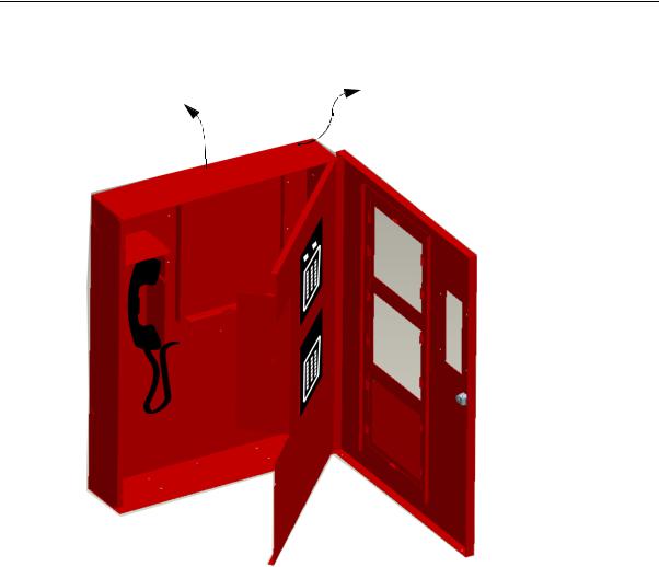
2.2.1Removing the SK-FFT Assembly from the Housing
If it should ever be necessary to remove the control panel assembly from the cabinet for repair, do so by removing the screws that hold the control panel in to the cabinet. Do not attempt to disassemble the circuit boards.
54711 |
2-1 |
SK-FFT Installation and Operation Manual
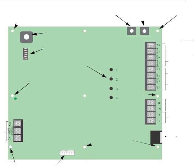
2.3SK-FFT Board Layout
Trouble
Relay
Mounting stud |
JumpStart |
Accept |
PZT
DIP Switch
Status LED’s
Mounting stud

 Power Status
LED
Non Power
Limited
Mounting |
Connector for FFT-24 |
stud |
|
Mounting stud
Mounting
stud
All circuits inherently power limited except the trouble relay
Mounting stud
Phone In
Phone Out Supervised
|
|
Power |
|
SLC IN |
Limited |
||
|
|
||
SLC Out |
|
|
|
|
|
|
|
Not |
|
|
|
Used |
|
|
|
DC |
|
|
|
Power |
|
|
|
Local
 Handset
Figure 2-1 Back view of SK-FFT
Figure 2-1 shows the circuit board that attaches to the cabinet. If you should need to remove the board assembly for repair, remove the seven mounting nuts which hold the assembly in the cabinet. Then lift the control board out of the cabinet.
2-2 |
54711 |

Before you Begin Installing
Answer LED |
General Trouble LED |
Active
(green)
Trouble
(amber)
Zone 1- |
Zone 9 - |
Zone 17 - |
Zone 8 |
Zone 16 |
Zone 24 |
Figure 2-2 SK-FFT Front View
Active (green)
Trouble
(amber
)
Zone 25 |
Zone 33 - |
Zone |
-Zone 32 |
Zone 40 |
41- |
|
|
Zone 48 |
Figure 2-3 FFT-24 Expander Front View for Zone 25 - 48
54711 |
2-3 |

SK-FFT Installation and Operation Manual
2.4Electrical Specifications
2.4.1Power Requirements
Voltage for the SK-FFT must be a power-limited, filtered, non resettable nominal 24
VDC source. The voltage source must be within the range of 17-29 VDC.
Table 2-1: Electrical Ratings
Circuits |
Voltage |
Current |
|
|
|
SLC Circuits |
32 V |
150 mA |
|
|
|
Audio Circuits |
17 V |
53 mA |
2.4.2Current Ratings
Maximum current ratings for determining backup battery requirements for alarm
(active) and standby conditions over the input voltage range of 17-29 VDC are shown in Table 2-2.
Table 2-2: SK-FFT Current Draw
|
Active |
Standby |
|
|
|
SK-FFT |
230 mA |
120 mA |
|
|
|
FFT-24 |
25 mA |
10 mA |
|
|
|
2-4 |
54711 |

Before you Begin Installing
2.5Wiring Specifications
Induced noise (transfer of electrical energy from one wire to another) can interfere with telephone communication or cause false alarms. To avoid induced noise, follow these guidelines:
•Isolate input wiring from high current output and power wiring. Do not pull one multi-conductor cable for the entire panel. Instead, separate the wiring as follows:
SLC loops |
Audio circuits |
Relay circuit |
|
•Do not pull wires from different groups through the same conduit. If you must run them together, do so for as short a distance as possible or use shielded cable.
Twisted, shielded wire on the Audio Circuits is recommended for maximum protection against EMI and AFI emissions and susceptibility. Connect the shield to earth ground at the panel. You must route high and low voltages separately.
•Route the wiring around the inside perimeter of the cabinet. It should not cross the circuit board where it could induce noise into the sensitive microelectronics or pick up unwanted RF noise from the high speed circuits. See Figure 2-4 for an example.
•High frequency noise, such as that produced by the inductive reactance of a speaker or bell, can also be reduced by running the wire through ferrite shield beads or by wrapping it around a ferrite toroid.
54711 |
2-5 |
SK-FFT Installation and Operation Manual
2.6Wire Routing
You must follow power-limited wiring techniques, which include maintaining onequarter inch spacing between power-limited and non-power limited circuits and separating high and low voltage circuits.
Power Limited |
Non-Power limited |
Relay Circuit |
Non power limited wiring must be run separately from power limited wiring
Figure 2-4 Wire Routing Example
2-6 |
54711 |
Section 3
Installation
3.1Mounting the Cabinet
Read the environmental specifications in Section 2.1 before mounting the SK-FFT cabinet. This will ensure that you select a suitable location.
The cabinet can be surface or flush mounted. Do NOT flush-mount in a wall designed as a fire break.
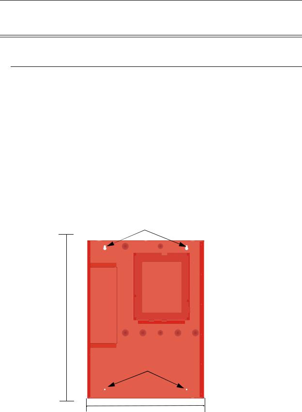
3.1.1Surface Mounting
The Cabinet can be mounted on the wall surface by using the mounting holes in the back of the cabinet (see Figure 3-1).
1.Insert two screws level with each other, 14" apart for the top cabinet key shaped holes. See Figure 3-1.
2.Hang the cabinet onto the two screws. Tighten the screws down.
3.Insert two screws into the two bottom mounting holes and tighten them snug to the cabinet.
Key Shaped Holes
26-½”
Bottom Mounting Holes
20"
Figure 3-1 Cabinet Mounting Holes
54711 |
3-1 |
SK-FFT Installation and Operation Manual
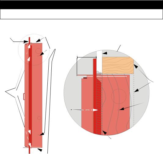
3.1.2Flush Mounting
This section describes how to flush mount the cabinet into a wall. To recess mount the cabinet you will need to have the optional trim ring P/N VIP-TR (ordered separately).
Follow these steps to recess mount the cabinet:
1.Remove the cabinet door and the dead front panel.
2.Cut a recess hole 20-1/4” W x 26-3/4” H (51.44 cm W x 67.95 cm H). There should be 1.5" to 1.75" of cabinet extruding from the wall, this should be measured from either the top edge or bottom edge to the exterior side of the sheet rock. (See
Figure 3-2.)
Important!
Do not insert the cabinet deeper than recommend above. If the cabinet is mounted to deep you will not be able to re-attach the door assembly.
3. Mount the cabinet to wall studs by inserting a screw through the cabinets side mounting holes into the wall stud.
Trim Ring
Cabinet |
Sheet Rock |
|
|
Mounting Hole |
|
1.5 to 1.75"
|
Mounting |
|
|
Studs |
|
Trim Ring |
|
|
Mounting |
|
|
Hole |
Cabinet |
|
Trim Ring |
||
Mounting Hole |
||
Mounting |
|
|
Hole |
|
 Sheet Rock
Side View of Cabinet
and Trim Ring
Figure 3-2 Detail of Flush Mounting with Trim Ring
3-2 |
54711 |
Loading...