


 Loading...
MODEL 5128/29
Fire Slave Communicator
Installation Manual
Part Number 150805 Rev E 11/06

Contents
Section 1 |
|
||
Introduction ......................................................................................................................................................... |
1 |
||
1.1 |
Features ............................................................................................................................................................... |
1 |
|
1.2 |
Optional Devices ................................................................................................................................................. |
2 |
|
1.3 |
UL Fire Listed Receivers Compatible with the 5128/29 .................................................................................... |
2 |
|
1.4 |
How to Use this Manual ...................................................................................................................................... |
2 |
|
1.5 |
How to Contact Silent Knight ............................................................................................................................. |
3 |
|
Section 2 |
|
||
Agency Requirements .......................................................................................................................... |
3 |
||
2.1 |
Telephone Requirements ..................................................................................................................................... |
3 |
|
2.2 |
FCC Warning ...................................................................................................................................................... |
4 |
|
2.3 |
UL Listings and Requirements ........................................................................................................................... |
4 |
|
Section 3 |
|
||
Panel Description and Installation ....................................................................................... |
5 |
||
3.1 |
Panel Description ................................................................................................................................................ |
5 |
|
|
3.1.1 |
Phone Line Monitors .................................................................................................................................... |
5 |
|
3.1.2 |
Watchdog Circuit.......................................................................................................................................... |
5 |
|
3.1.3 |
Power Loss Reporting................................................................................................................................... |
5 |
|
3.1.4 |
EEPROM ...................................................................................................................................................... |
5 |
|
3.1.5 |
DC Power...................................................................................................................................................... |
6 |
|
3.1.6 |
Indicator Lights............................................................................................................................................. |
6 |
3.2 |
Environmental ..................................................................................................................................................... |
7 |
|
3.3 |
Wiring ................................................................................................................................................................. |
7 |
|
|
3.3.1 |
Wiring Precautions ....................................................................................................................................... |
7 |
|
3.3.2 |
Connector Descriptions................................................................................................................................. |
7 |
|
3.3.3 |
Earth Ground Impedance .............................................................................................................................. |
7 |
|
3.3.4 Wiring and Board Layout Diagram .............................................................................................................. |
8 |
|
|
3.3.5 |
Electrical Ratings.......................................................................................................................................... |
8 |
|
3.3.6 |
Wire Routing................................................................................................................................................. |
9 |
3.4 |
DC Power Connection ...................................................................................................................................... |
10 |
|
3.5 |
Mounting and Grounding .................................................................................................................................. |
11 |
|
|
3.5.1 |
Preventing Water Damage .......................................................................................................................... |
11 |
|
3.5.2 Grounding the 5129 Board ......................................................................................................................... |
11 |
|
150805 |
i |

Model 5128/29 Fire Slave Communicator Installation Manual |
|
||
|
3.5.3 Grounding the 5129 Cover.......................................................................................................................... |
11 |
|
3.6 |
Channel Operation and Wiring ......................................................................................................................... |
12 |
|
|
3.6.1 |
Dry Contact ................................................................................................................................................. |
12 |
|
3.6.2 Voltage Input (Active High) ....................................................................................................................... |
12 |
|
3.7 |
AC Monitoring .................................................................................................................................................. |
13 |
|
|
3.7.1 |
Voltage Input—Active High....................................................................................................................... |
13 |
|
3.7.2 |
Dry Contact ................................................................................................................................................. |
13 |
|
3.7.3 Monitor AC (Available with the Model 5129 only) ................................................................................... |
14 |
|
3.8 |
Relay Connection .............................................................................................................................................. |
15 |
|
3.9 |
Telephone Line Connection .............................................................................................................................. |
16 |
|
3.10 |
Remote Annunciator Installation ...................................................................................................................... |
17 |
|
|
3.10.1 Model 5230 Connection.............................................................................................................................. |
17 |
|
Section 4 |
|
||
Normal Operation ...................................................................................................................................... |
18 |
||
4.1 |
5230 Operation .................................................................................................................................................. |
18 |
|
|
4.1.1 |
Power LED Indicator .................................................................................................................................. |
18 |
|
4.1.2 |
Buzzer ......................................................................................................................................................... |
18 |
|
4.1.3 |
5230 Key Functions .................................................................................................................................... |
19 |
4.2 |
Operating Modes ............................................................................................................................................... |
19 |
|
Section 5 |
|
||
Programming ................................................................................................................................................... |
20 |
||
5.1 |
UL 864 Programming Requirements ................................................................................................................ |
20 |
|
5.2 |
Programming with the 5230 Remote Annunciator ........................................................................................... |
21 |
|
|
5.2.1 Special Characters for Dialing .................................................................................................................... |
22 |
|
5.3 |
Programming with the 5541 Downloading Software ........................................................................................ |
22 |
|
5.4 |
Programming Options ....................................................................................................................................... |
22 |
|
Section 6 |
|
||
Reporting .............................................................................................................................................................. |
30 |
||
6.1 |
Reporting Codes ................................................................................................................................................ |
31 |
|
Section 7 |
|
||
Troubleshooting .......................................................................................................................................... |
32 |
||
7.1 |
System Messages ............................................................................................................................................... |
32 |
|
7.2 |
Silencing Troubles ............................................................................................................................................. |
32 |
|
ii |
150805 |

SECTION 1
INTRODUCTION
The Silent Knight Model 5128/29 is a low-cost slave communicator that meets the requirements for UL 864, NFPA 72 Fire Alarm Systems for Central Station Service and NFPA 72 Remote Supervising Station Fire Alarm Systems.
1.1Features
•Compatibility with the Security Industry Association (SIA) reporting format and several other standard reporting formats.
•Four channel (zone) inputs for system status reporting: fire alarm (channel or zone 1); system trouble– channel 2 (or zone 2); supervisory–channel 3 (or zone 3); and miscellaneous–channel 4 (or zone 4).
•Optional two-number dialing with same or different account codes and reporting formats. Alarms, troubles, and tests can be programmed to be reported to either or both numbers.
•Programmable as rotary-only or as Touch-Tone/rotary dialing.
•Built-in dual phone line-seizure circuit.
•Dual phone line monitor circuits.
•Transient voltage protection of phone lines.
•Built-in audible trouble buzzer.
•One relay output, programmable for alarm, trouble conditions, or trouble excluding low AC.
•Light-emitting diodes (LEDs), visible from front of enclosure, indicating: trouble condition (yellow); presence of DC power (green), phone line 1 trouble (red); and phone line 2 trouble (red).
•Easy, English-language programming using Model 5230 Remote Annunciator.
•Fuseless design, 24 VDC.
•Electrically erasable read-only memory (EEPROM) for nonvolatile storage of all programmable option data. Eliminates the need to reprogram the communicator if power is lost.
•Built-in watchdog circuit that monitors the operation of the 5128/29 and resets the communicator if a fault is detected.
•Active high or contact closure input.
•Model 5129 can directly monitor control panel’s primary power.
•Compatibility with many Underwriters Laboratories (UL) Fire Listed receivers. (See Section 1.3 for list.)
•Model 5128 housed in 8-5/8" x 4" x 1-3/8" enclosure for mounting inside control panel.
•Model 5129 housed in a 10" x 10" metal enclosure.
150805 |
1 |

Model 5128/29 Fire Slave Communicator Installation Manual
1.2Optional Devices
The following accessories are available for use with the Model 5128/29:
•5230 Remote Annunciator for programming, troubleshooting, and system operation. Only one model 5230 can be used.
•Cable for 5230, P/N 130294.
•5541 Downloading Software for remote programming. (Must be Revision 3.7 or later.)
•5530 Modem. Required if the 5541 downloading software is used.
1.3UL Fire Listed Receivers Compatible with the 5128/29
The following UL Listed receivers are compatible with the 5128/29:
RECEIVER |
FORMATS |
|
|
|
|
Silent Knight Model 9000, 9500, or 9800 |
BFSK14 |
Note: The Model 9000 receiver does not |
BFSK23 |
accept CID format. |
SK 3/1 |
|
|
|
SK 4+2 |
|
SIA8 |
|
SIA20 |
|
Contact ID (CID) |
|
|
Osborn & Hoffman Quickalert |
SK 3/1 |
|
SK 4+2 |
|
SIA8 |
|
SIA20 |
|
BFSK14 |
|
BFSK23 |
|
|
Ademco 685 |
SK 3/1 |
|
SK 4+2 |
|
|
FBI CP220 |
SK 3/1 |
|
SK 4+2 |
|
|
Radionics D6500 |
BFSK 1400 |
|
BFSK 2300 |
|
|
1.4How to Use this Manual
This manual is intended for use with Revision P or higher of the 5128/29 printed circuit board. If you are installing or servicing a different revision level and do not have the correct manual, contact Silent Knight for the correct information.
In this manual, a rectangle represents a key that you press if you are using the optional Model 5230 Remote Annunciator. For example, “Press ENTER ” means “Press the <ENTER> key.”
2 |
150805 |

Agency Requirements
1.5How to Contact Silent Knight
For questions and problems with Silent Knight products, contact Silent Knight Technical Support at 800-328-0103 (or 763-493-6455). To order parts, contact Silent Knight Sales at 800-446-6444
(or 763-493-6435).
SECTION 2
AGENCY REQUIREMENTS
2.1Telephone Requirements
1.If requested by the telephone company, the following information must be provided before connecting this device to the phone lines:
A.Manufacturer: Silent Knight
B.Model Number: 5128/29
C.FCC Registration Number: AC6USA-75160-AL-E Ringer equivalence: 0.1B
D.Type of jack (to be installed by the telephone company): RJ31X
2.This device may not be directly connected to coin telephone or party line services.
3.This device cannot be adjusted or repaired in the field. In case of trouble with the device, notify the installing company or return:
Silent Knight
7550 Meridian Circle Maple Grove, MN 55369 763-493-6455 800-328-0103
4.If the Model 5128/29 causes harm to the telephone network, the telephone company will notify the user in advance that temporary discontinuance of service may be required. If advance notice is not practical, the telephone company will notify the user as soon as possible. The user has the right to file a complaint with the Federal Communications Commission if he or she believes it is necessary.
5.The telephone company may make changes in its facilities, equipment, operations, or procedures that could affect the operation of the equipment. If this happens, the telephone company will provide advance notice so that you can make the necessary modifications to maintain uninterrupted service.
150805 |
3 |
Model 5128/29 Fire Slave Communicator Installation Manual
2.2FCC Warning
WARNING:
This device has been verified to comply with FCC Rules Part 15. Operation is subject to the following conditions: (1) This device may not cause radio interference, and (2) This device must accept any interference received, including interference that may cause undesired operation.
2.3UL Listings and Requirements
Model |
Listed As: |
5128
Signaling device subassembly for use in Fire Alarm Systems for Central
Station Service.
Signaling device subassembly for use in Remote Supervising Fire Alarm
Systems.
5129
Signaling device for use in Fire Alarm Systems for Central Station Service.
Signaling device for use in Remote Supervising Fire Alarm Systems.
All UL installations must comply with the requirements described below. Refer to the control unit’s installation manual for complete information.
5128 Requirements:
The 5128 must be mounted within a UL listed compatible fire control panel.
5129 Requirements:
The 5129 and the UL listed compatible fire control must be installed in the same room. All wiring between the 5129 and the UL Listed compatible fire control panel must be enclosed in conduit. The 5129 must be mounted within 20 feet of the fire control.
Requirements for both 5128 and 5129:
All electrical connections must comply with the ratings shown in section 3.3.5. In a remote signaling installation, the control unit, slave dialer, and receiver at the remote site must all be UL listed for remote signaling.
Install in accordance with NFPA 70 and NFPA 72.
4 |
150805 |

Panel Description and Installation
SECTION 3
PANEL DESCRIPTION AND INSTALLATION
CAUTION:
To avoid the risk of electrical shock, make sure the main control power is OFF when wiring. DO NOT apply power until wiring is completed following the procedures described in this manual.
3.1Panel Description
3.1.1Phone Line Monitors
The 5128/29 dialer has two phone line monitor circuits, which detect phone line faults by monitoring their voltages. These circuits feature a 40 to 90 second delay before a line fault is reported as a trouble. When a fault is detected for longer than this amount of time, the audible trouble signal will sound, the message will be displayed on the 5230 annunciator liquid crystal display (LCD) (if used), and the trouble will be reported to the central station.
Note: To comply with industry standards, this product is equipped with line seizure. This means that any time the system’s dialer needs to communicate with the central station, it will NOT be possible to use any telephones that are on the same line(s) as the fire system. Normally this condition will last less than one minute, but could last for as long as 15 minutes under adverse telephone circuit conditions.
3.1.2Watchdog Circuit
If the 5128/29 stops running, the watchdog circuit automatically detects the problem and attempts to resume normal operation by resetting the communicator. Each time the watchdog circuit resets the system, it also sounds the trouble signal.
3.1.3Power Loss Reporting
The 5128/29 will report low AC conditions. It can monitor a contact closure AC failure output. The 5129 can also monitor the control panel’s main AC power input.
The AC report delay time is programmable. See Section 5, Step 24.
3.1.4EEPROM
The electrically erasable read-only memory (EEPROM) is used to store specific information such as system configuration, telephone numbers, reporting format, and account numbers. The EEPROM retains the programmed information even when all electrical power is removed. It can be programmed more than 1,000 times without losing its ability to store information.
150805 |
5 |
Model 5128/29 Fire Slave Communicator Installation Manual
3.1.5DC Power
The 5128/29 operates on 18-40 VDC rectified power from the main fire control panel.
3.1.6Indicator Lights
The 5128/29 has four LEDs to indicate status.
TROUBLE LED (yellow)
ON - A system trouble condition exists.
OFF - No trouble condition exists.
Flashing - Silenced Trouble
DC POWER LED (green)
ON - The panel is running on DC power.
OFF - The panel has lost all power.
Flashing - The panel is reporting.
PHONE LINE 1 LED (red)
ON - Phone line 1 has a trouble condition. OFF - Normal condition.
Flashing - Communication Trouble (Failed to report using this Line)
PHONE LINE 2 LED (red)
ON - Phone line 2 has a trouble condition. OFF - Normal condition.
Flashing - Communication Trouble (Failed to report using this Line)
6 |
150805 |
Panel Description and Installation
3.2Environmental
It is important to protect the Model 5128/29 from water. To prevent water damage, the following conditions should be AVOIDED when installing the units:
•Intended for indoor use only.
•Do not mount directly on exterior walls, especially masonry walls (condensation)
•Do not mount directly on exterior walls below grade (condensation)
•Protect from plumbing leaks
•Protect from splash caused by sprinkler system inspection ports
•Do not mount in areas with humidity-generating equipment (such as dryers, production machinery)
When selecting a location to mount the Model 5128/29, the unit should be mounted where it will NOT be exposed to temperatures outside the range of 0°C-49°C (32°F-120°F) or humidity outside the range of 10%-93% at 30°C (86°F) noncondensing.
3.3Wiring
3.3.1Wiring Precautions
High and low voltage must be separated by at least one-quarter inch. See Section 3.3.6 for more information. High current input/output: AC monitoring (if monitored directly)
Low current input/output: 24 VDC power and channel (zone) wiring Audio input/output: Telephone wiring
High frequency noise, such as that produced by the inductive reactance of a bell, can also be reduced by running the wire through ferrite shield beads or by wrapping it around a ferrite toroid.
3.3.2 |
Connector Descriptions |
|
|
|
|
|
|
|
|
PIN CONNECTOR |
FUNCTION |
|
|
|
|
|
|
P1 |
DC power |
|
|
|
|
|
|
P2 |
Channel (zone) inputs |
|
|
|
|
|
|
P4 |
5230 connect |
|
|
|
|
|
|
P5 |
Low AC channel input |
|
|
|
|
3.3.3 |
Earth Ground Impedance |
|
|
All circuits on this panel have an earth ground impedance of zero (0) Ohms.
150805 |
7 |
Model 5128/29 Fire Slave Communicator Installation Manual
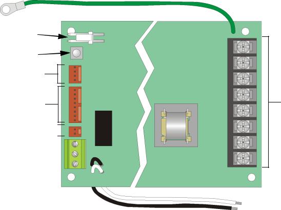
3.3.4Wiring and Board Layout Diagram
Earth Ground
DC Power
(See Section 3.4)
Silence Button
(See Section 7.2)
5230 Connector
(See Section 3.10.1)
Channel Inputs
(See Section 3.6)
Low AC Channel
(See Section 3.7) 
Relay Terminals
Contact Rating 1A @ 24VDC or 24VAC
(See Section 3.8)
All Circuits Supervised Power Limited except Direct AC Monitoring, which is supervised only
Figure 3-1 Model 5128/29 Wiring and Board Layout
To Telco
Lines (See
Section 3.9)
Direct AC Monitoring
(See Section 3.7.3)
3.3.5 Electrical Ratings
PRIMARY DC |
VDC: 18 - 40 |
|
|
|
Current draw, standby at 24 VDC |
|
143 mA max. with annunciator attached |
|
84 mA max. without annunciator |
|
Current draw, alarm at 24 VDC |
|
227 mA max. with annunciator attached |
|
154 mA max. without annunciator |
AC RATING |
120 VAC @ 60Hz, 45 mA max. |
|
|
CHANNEL (ZONE) INPUTS* |
18 - 30 VDC input |
Active High |
15 mA max. current draw |
Dry Contacts |
4.7 VDC, 6 mA max. |
MAX. WATCHDOG RESPONSE |
50 seconds |
|
|
* Supervised for opens only. No ground fault detection is provided.
8 |
150805 |

Panel Description and Installation
3.3.6Wire Routing
High voltage and low voltage inputs must be separated by at least one-quarter inch and must be wired through different knockout holes in the fire control cabinet to maintain the separation.
Figure 3-2 below shows an example of how to route the wire if you are using the model 5129. If you are using the 5128, refer to the fire control panel installation manual for wire routing instructions.
Cable Clamp See instructions
Below
Board Ground
To Telco
Lines
Cable Tie
Must be enclosed in conduit.
From AC
Figure 3-2 Routing Wire for the 5129
150805 |
9 |
Loading...