


 Loading...
INTELLIKNIGHT®
MODEL 5700
Addressable Fire Alarm Control Panel
Installation and
Operations Manual
Document 151295
10/30/14 Rev: S
P/N 151295:S ECN: 14-0724

Installation Procedure
Installation Precautions - Adherence to the following will aid in problem-free installation with long-term reliability: WARNING - Several different sources of power can be connected to the fire alarm control panel. Disconnect all sources of power before servicing. Control unit and associated equipment may be damaged by removing and/or inserting cards, modules, or interconnecting cables while the unit is energized. Do not attempt to install, service, or operate this unit until manuals are read and understood. CAUTION - System Re-acceptance Test after Software Changes: To ensure proper system operation, this product must be tested in accordance with NFPA 72 after any programming operation or change in site-specific software. Re-acceptance testing is required after any change, addition or deletion of system components, or after any modification, repair or adjustment to system hardware or wiring. All components, circuits, system operations, or software functions known to be affected by a change must be 100% tested. In addition, to ensure that other operations are not inadvertently affected, at least 10% of initiating devices that are not directly affected by the change, up to a maximum of 50 devices, must also be tested and proper system operation verified. This system meets NFPA requirements for operation within the range of 0°C-49°C (32°F-120°F) or humidity within the range of 10%-93% at 30°C (86°F) noncondensing. However, the useful life of the system's standby batteries and the electronic components may be adversely affected by extreme temperature ranges and humidity. Therefore, it is recommended that this system and its peripherals be installed in an environment with a normal room temperature of 15-27º C/60-80º F. Verify that wire sizes are adequate for all initiating and indicating device loops. Most devices cannot tolerate more than a 10% I.R. drop from the specified device voltage. Like all solid state electronic devices, this system may operate erratically or can be damaged when subjected to lightning induced transients. Although no system is completely immune from lightning transients and interference, proper grounding will reduce susceptibility. Overhead or outside aerial wiring is not recommended, due to an increased susceptibility to nearby lightning strikes. Consult with the Technical Services Department if any problems are anticipated or encountered. Disconnect AC power and batteries prior to removing or inserting circuit boards. Failure to do so can damage circuits. Remove all electronic assemblies prior to any drilling, filing, reaming, or punching of the enclosure. When possible, make all cable entries from the sides or rear. Before making modifications, verify that they will not interfere with battery, transformer, or printed circuit board location. Do not tighten screw terminals more than 9 in-lbs. Over-tightening may damage threads, resulting in reduced terminal contact pressure and difficulty with screw terminal removal. fire alarm control panels contain static-sensitive components. Always ground yourself with a proper wrist strap before handling any circuits so that static charges are removed from the body. Use static suppressive packaging to protect electronic assemblies removed from the unit.
Follow the instructions in the installation, operating, and programming manuals. These instructions must be followed to avoid damage to the control panel and associated equipment. Fire Alarm Control Panel (FACP) operation and reliability depend upon proper installation.
While installing a fire alarm system may make lower insurance rates possible, it is not a substitute for fire insurance! An automatic fire alarm system - typically made up of smoke detectors, heat detectors, manual pull stations, audible warning devices, and a fire alarm control with remote notification capability - can provide early warning of a developing fire. Such a system, however, does not assure protection against property damage or loss of life resulting from a fire. Any fire alarm system may fail for a variety of reasons: Smoke detectors may not sense fire where smoke cannot reach the detectors such as in chimneys, in walls, or roofs, or on the other side of closed doors. Smoke detectors also may not sense a fire on another level or floor of a building. A second floor detector, for example, may not sense a first floor or basement fire. Furthermore, all types of smoke detectors, including ionization and photoelectric types, have sensing limitations. No type of smoke detector can sense every kind of fire caused by carelessness and safety hazards like smoking in bed, violent explosions, escaping gas, improper storage of flammable materials, overloaded electrical circuits, children playing with matches, or arson.
IMPORTANT! Smoke detectors must be installed in the same room as the control panel and in rooms used by the system for the connection of alarm transmission wiring, communications, signaling, and/or power. If detectors are not so located, a developing fire may damage the alarm system, crippling its ability to report a fire. Audible warning devices such as bells may not alert people if these devices are located on the other side of closed or partly open doors or are located on another floor of a building. A fire alarm system will not operate without any electrical power. If AC power fails, the system will operate from standby batteries only for a specified time. Rate-of-Rise heat detectors may be subject to reduced sensitivity over time. For this reason, the rate-of-rise feature of each detector should be tested at least once per year by a qualified fire protection specialist. Equipment used in the system may not be technically compatible with the control. It is essential to use only equipment listed for service with your control panel. Telephone lines needed to transmit alarm signals from a premise to a central monitoring station may be out of service or temporarily disabled. The most common cause of fire alarm malfunctions, however, is inadequate maintenance. All devices and system wiring should be tested and maintained by professional fire alarm installers following written procedures supplied with each device. System inspection and testing should be scheduled monthly or as required by national and/or local fire codes. Adequate written records of all inspections should be kept.

Contents
Contents
Section 1 |
|
|
Introduction .............................................................................................................................................. |
1-1 |
|
1.1 |
Overview of Basic System ........................................................................................................ |
1-1 |
|
1.1.1 Hardware Features ............................................................................................................ |
1-1 |
|
1.1.2 Software Features .............................................................................................................. |
1-2 |
1.2 |
About this Manual ..................................................................................................................... |
1-2 |
|
1.2.1 Terms Used in this Manual ................................................................................................ |
1-2 |
1.3 |
Compatible Products ................................................................................................................ |
1-3 |
1.4 |
How to Contact Silent Knight .................................................................................................... |
1-4 |
Section 2 |
|
|
Agency Listings, Approvals, and Requirements ................................... |
2-1 |
|
2.1 |
Federal Communications Commission (FCC) .......................................................................... |
2-1 |
2.2 |
Underwriters Laboratories (UL) ................................................................................................ |
2-2 |
|
2.2.1 Requirements for All Installations ...................................................................................... |
2-2 |
|
2.2.2 Requirements for Central Station Fire Alarm Systems ...................................................... |
2-3 |
|
2.2.3 Requirements for Local Protected Fire Alarm Systems ..................................................... |
2-3 |
|
2.2.4 Requirements for Remote Station Protected Fire Alarm Systems ..................................... |
2-3 |
Section 3 |
|
|
Before You Begin Installing ............................................................................................... |
3-1 |
|
3.1 |
What’s in the Box? ................................................................................................................... |
3-1 |
3.2 |
Environmental Specifications ................................................................................................... |
3-1 |
3.3 |
Electrical Specifications ............................................................................................................ |
3-2 |
3.4 |
Wiring Specifications ................................................................................................................ |
3-3 |
3.5 |
Board Assembly Diagram ......................................................................................................... |
3-4 |
3.6 |
Calculating Current Draw and Standby Battery ........................................................................ |
3-5 |
|
3.6.1 Current Draw Worksheet Requirements ............................................................................ |
3-5 |
|
3.6.2 Current Draw Worksheet for SK SLC Devices ................................................................... |
3-5 |
|
3.6.3 Current Draw Worksheet for SD SLC Devices .................................................................. |
3-8 |
|
3.6.4 Maximum Battery Standby Load ........................................................................................ |
3-9 |
3.7 |
Installation Tasks Overview .................................................................................................... |
3-10 |
Section 4 |
|
|
Control Panel Installation ...................................................................................................... |
4-1 |
|
4.1 |
Mounting the Control Panel Cabinet ........................................................................................ |
4-1 |
|
4.1.1 Preventing Water Damage ................................................................................................. |
4-1 |
|
4.1.2 Removing the 5700 Assembly from the Housing ............................................................... |
4-1 |
|
4.1.3 Dead Front Installation and removal .................................................................................. |
4-1 |
|
4.1.3.1 Installing the Dead Front .......................................................................................... |
4-2 |
1
Contents |
|
|
|
|
4.1.3.2 Dead Front Removal ................................................................................................ |
4-2 |
|
4.2 |
AC Connection ......................................................................................................................... |
4-3 |
|
4.3 |
Battery Connection ................................................................................................................... |
4-4 |
|
|
4.3.1 RBB Accessory Cabinet ..................................................................................................... |
4-5 |
|
|
4.3.1.1 |
Installing the RBB Accessory Cabinet and Batteries ............................................... |
4-5 |
4.4 |
SBUS Wiring ............................................................................................................................ |
4-7 |
|
|
4.4.1 Calculating Wiring distance for SBUS modules ................................................................. |
4-7 |
|
|
4.4.2 Wiring Configurations ......................................................................................................... |
4-9 |
|
|
4.4.2.1 How to Power SBUS Devices From Auxiliary Power Supply ................................... |
4-9 |
|
4.5 |
5860emote Annunciator Installation ....................................................................................... |
4-10 |
|
|
4.5.1 Mounting the 5860 ........................................................................................................... |
4-11 |
|
|
4.5.1.1 |
Flush Mounting ....................................................................................................... |
4-13 |
|
4.5.1.2 |
Surface Mounting ................................................................................................... |
4-14 |
|
4.5.2 Model 5860 Connection to the Panel ............................................................................... |
4-14 |
|
4.65824 Serial/Parallel Printer Interface Module Installation 4-15
4.6.1 Selecting 5824 Options .................................................................................................... |
4-16 |
|
4.7 5880 LED Driver Module ........................................................................................................ |
4-17 |
|
4.7.1 5880 Board Layout ........................................................................................................... |
4-17 |
|
4.7.2 FACP Connection ............................................................................................................ |
4-18 |
|
4.7.3 LED Wiring ....................................................................................................................... |
4-19 |
|
4.7.4 Dry Contact Wiring ........................................................................................................... |
4-19 |
|
4.8 5865-3 / 5865-4 LED Annunciator Installation ........................................................................ |
4-20 |
|
4.8.1 FACP Connection ............................................................................................................ |
4-21 |
|
4.8.2 5865 Mounting ................................................................................................................. |
4-21 |
|
4.9 |
Configuring Modules .............................................................................................................. |
4-22 |
4.9.1 Assigning Module IDs ...................................................................................................... |
4-22 |
|
4.10 |
Telephone Connection ........................................................................................................... |
4-23 |
4.11 Notification Appliance/Auxiliary Power Circuits ...................................................................... |
4-23 |
|
4.11.1 Conventional Notification Appliance ............................................................................... |
4-23 |
|
|
4.11.1.1 Class B Notification Wiring .................................................................................... |
4-24 |
|
4.11.1.2 Class A Notification Wiring .................................................................................... |
4-25 |
4.11.2 Auxiliary Power Installation ............................................................................................. |
4-26 |
|
|
4.11.2.1 Door Holder Power ................................................................................................ |
4-26 |
|
4.11.2.2 Constant Power ..................................................................................................... |
4-27 |
|
4.11.2.3 Resettable Power .................................................................................................. |
4-27 |
|
4.11.2.4 Sounder Sync Power ............................................................................................ |
4-27 |
4.12 |
On-Board Relays (Conventional) ........................................................................................... |
4-27 |
4.12.1 Common Trouble Relay .................................................................................................. |
4-27 |
|
4.12.2 Programmable Relays .................................................................................................... |
4-27 |
|
4.13 |
Remote Station Applications .................................................................................................. |
4-28 |
4.13.1 Keltron Model 3158 Installation ...................................................................................... |
4-28 |
|
4.13.2 City Box Connection Using the 5220 Module ................................................................. |
4-29 |
|
4.13.3 NFPA 72 Polarity Reversal ............................................................................................. |
4-30 |
|
|
4.13.3.1 Using the 5220 Module ......................................................................................... |
4-30 |
|
4.13.3.2 Using the 7644-L8 Module .................................................................................... |
4-31 |
4.13.4 Using the SD500-ARM Addressable Relay Module ....................................................... |
4-31 |
|
4.13.5 Using a MR-201/T Control Relay From Air Products ...................................................... |
4-33 |
|
4.13.6 Transmitter Activated by Dry Contacts ........................................................................... |
4-34 |
|
2

Contents
Section 5 |
|
||
SK and SD SLC Device Installation .......................................................................... |
5-1 |
||
5.1 |
List of SK SLC Devices ............................................................................................................ |
5-1 |
|
5.2 |
List of SD SLC Devices ............................................................................................................ |
5-2 |
|
5.3 |
Maximum Number of Devices .................................................................................................. |
5-3 |
|
5.4 |
Wiring Requirements for SLC Devices ..................................................................................... |
5-3 |
|
|
5.4.1 |
Wiring SLC in Style 4 (Class B) Configuration ................................................................... |
5-3 |
|
5.4.2 Wiring SLC Devices in Style 6 & 7 (Class A) |
|
|
|
|
Configuration 5-5 |
|
5.5 |
SK Detector Installation ............................................................................................................ |
5-6 |
|
|
5.5.1 Wiring SK Detectors ........................................................................................................... |
5-6 |
|
5.6 |
Addressing SK SLC Devices .................................................................................................... |
5-7 |
|
5.7 |
SD Detector Installation ............................................................................................................ |
5-8 |
|
|
5.7.1 Wiring SD Detectors .......................................................................................................... |
5-8 |
|
5.8 |
Addressing SD SLC Devices .................................................................................................... |
5-9 |
|
|
5.8.1 SD505-APS, SD505-AHS, & SD505-AIS ........................................................................... |
5-9 |
|
|
5.8.2 SLC Devices with DIP Switches ...................................................................................... |
5-10 |
|
Section 6 |
|
||
Programming Overview ........................................................................................................... |
6-1 |
||
6.1 |
JumpStart Autoprogramming ................................................................................................... |
6-1 |
|
|
6.1.1 Input Points ........................................................................................................................ |
6-1 |
|
|
6.1.2 Output Points ..................................................................................................................... |
6-1 |
|
|
6.1.3 Running JumpStart ............................................................................................................ |
6-2 |
|
6.2 |
Mapping Overview .................................................................................................................... |
6-3 |
|
|
6.2.1 Input Point Mapping ........................................................................................................... |
6-4 |
|
|
6.2.2 Output Circuit Mapping ...................................................................................................... |
6-5 |
|
|
6.2.3 Zone Event Mapping .......................................................................................................... |
6-6 |
|
|
6.2.4 Mapping LED Points .......................................................................................................... |
6-8 |
|
6.3 |
Programming Using the 5660 Silent Knight Software Suite ..................................................... |
6-9 |
|
6.4 |
Programming Using an Annunciator ........................................................................................ |
6-9 |
|
|
6.4.1 Entering / Exiting the Program Menu ................................................................................. |
6-9 |
|
|
6.4.2 Moving through the Menus .............................................................................................. |
6-10 |
|
|
6.4.3 Selecting Options and Entering Data ............................................................................... |
6-10 |
|
|
6.4.4 Editing Keys ..................................................................................................................... |
6-11 |
|
6.5 |
Programming Menu Quick Reference .................................................................................... |
6-12 |
|
Section 7 |
|
||
Programming ......................................................................................................................................... |
7-1 |
||
7.1 |
UL 864 Programming Requirements ........................................................................................ |
7-1 |
|
7.2 |
Modules .................................................................................................................................... |
7-2 |
|
|
7.2.1 Edit Modules ...................................................................................................................... |
7-2 |
|
|
7.2.1.1 Naming Modules ...................................................................................................... |
7-2 |
|
|
7.2.1.2 Module, Wiring Class ............................................................................................... |
7-2 |
|
|
7.2.2 Adding a Module ................................................................................................................ |
7-2 |
|
|
7.2.3 Deleting a Module .............................................................................................................. |
7-3 |
|
|
7.2.4 View Module List ................................................................................................................ |
7-3 |
|
3
Model 5700 Installation Manual |
|
||
7.3 |
Zone ......................................................................................................................................... |
|
7-3 |
|
7.3.1 Edit Zone ............................................................................................................................ |
7-3 |
|
|
7.3.1.1 |
Edit Zone Name ....................................................................................................... |
7-4 |
|
7.3.1.2 |
Edit Zone Properties ................................................................................................ |
7-4 |
|
7.3.1.3 |
Zone Outputs ........................................................................................................... |
7-6 |
|
7.3.1.4 |
Cadence Patterns .................................................................................................... |
7-8 |
|
7.3.1.5 |
Zone Accessory Options .......................................................................................... |
7-9 |
|
7.3.2 Add Zone ........................................................................................................................... |
7-9 |
|
|
7.3.3 Delete Zone ....................................................................................................................... |
7-9 |
|
|
7.3.4 View Zone Points ............................................................................................................... |
7-9 |
|
7.4 |
Group ..................................................................................................................................... |
|
7-10 |
|
7.4.1 Edit Group ........................................................................................................................ |
7-10 |
|
|
7.4.1.1 |
Edit Group Name ................................................................................................... |
7-10 |
|
7.4.1.2 |
Edit Group Properties ............................................................................................. |
7-11 |
|
7.4.2 Add Group ........................................................................................................................ |
7-13 |
|
|
7.4.3 Delete Group .................................................................................................................... |
7-13 |
|
|
7.4.4 View Group Points ........................................................................................................... |
7-13 |
|
|
7.4.5 Edit Output Group Templates .......................................................................................... |
7-14 |
|
7.5 |
Point ....................................................................................................................................... |
|
7-15 |
|
7.5.1 Point Programming For SLC ............................................................................................ |
7-15 |
|
|
7.5.2 Point Programming For Internal or External Power Module ............................................ |
7-18 |
|
|
7.5.3 Point Programming For 5880 and 5865 Modules ............................................................ |
7-20 |
|
|
7.5.4 Assigning a Name to a Points .......................................................................................... |
7-20 |
|
7.6 |
System Options ...................................................................................................................... |
7-21 |
|
|
7.6.1 Reporting Account ........................................................................................................... |
7-21 |
|
|
7.6.1.1 |
Edit Accounts ......................................................................................................... |
7-21 |
|
7.6.1.2 |
Auto Test Time ....................................................................................................... |
7-24 |
|
7.6.2 Phone Lines ..................................................................................................................... |
7-24 |
|
|
7.6.2.1 |
Dialing Prefix .......................................................................................................... |
7-25 |
|
7.6.2.2 Number of Answer Rings ....................................................................................... |
7-25 |
|
|
7.6.2.3 |
Dial Option (TouchTone or Pulse) .......................................................................... |
7-25 |
|
7.6.2.4 |
Rotary Format ........................................................................................................ |
7-25 |
|
7.6.2.5 |
Line Monitor ........................................................................................................... |
7-25 |
|
7.6.2.6 Answering Machine Bypass ................................................................................... |
7-26 |
|
|
7.6.3 Sys. Event Outputs .......................................................................................................... |
7-26 |
|
|
7.6.3.1 |
Trouble Events ....................................................................................................... |
7-26 |
|
7.6.3.2 System Alarm Cadence ......................................................................................... |
7-27 |
|
|
7.6.4 Time Options .................................................................................................................... |
7-27 |
|
|
7.6.4.1 |
Water Flow Delay ................................................................................................... |
7-28 |
|
7.6.4.2 |
Alarm Verification Time .......................................................................................... |
7-28 |
|
7.6.4.3 Low AC Report Delay ............................................................................................. |
7-28 |
|
|
7.6.4.4 |
Clock Display Format (AM/PM or Military) ............................................................. |
7-28 |
|
7.6.4.5 Change AC Line Frequency ................................................................................... |
7-29 |
|
|
7.6.5 Miscellaneous Options ..................................................................................................... |
7-29 |
|
|
7.6.5.1 |
Synchronize Strobes Active During Silence ........................................................... |
7-29 |
|
7.6.5.2 |
Auto Display Oldest Event ..................................................................................... |
7-29 |
|
7.6.5.3 |
Report by Zone or by Point .................................................................................... |
7-29 |
|
7.6.5.4 |
Single Key Acknowledge ....................................................................................... |
7-30 |
|
7.6.6 Daylight Savings .............................................................................................................. |
7-30 |
|
|
7.6.6.1 |
Automatic Daylight Savings Adjustment ................................................................ |
7-30 |
|
7.6.6.2 |
Daylight Saving Time Start and End ...................................................................... |
7-30 |
|
7.6.7 Edit Banner ...................................................................................................................... |
7-31 |
|
|
7.6.8 SLC Family ...................................................................................................................... |
7-31 |
|
7.7 |
JumpStart Autoprogramming ................................................................................................. |
7-32 |
|
4

Contents |
|
|
|
7.8 |
Computer Account .................................................................................................................. |
7-32 |
|
7.9 |
Access Codes ........................................................................................................................ |
7-33 |
|
|
7.9.1 Profile Edit Menu .............................................................................................................. |
7-34 |
|
|
7.9.1.1 Edit Name .............................................................................................................. |
7-34 |
|
|
7.9.1.2 |
Edit Access Code ................................................................................................... |
7-34 |
|
7.9.1.3 |
Panel Functions ..................................................................................................... |
7-34 |
Section 8 |
|
|
|
System Operation ............................................................................................................................ |
8-1 |
||
8.1 |
Default Codes: .......................................................................................................................... |
8-1 |
|
8.2 |
Annunciator Description ........................................................................................................... |
8-1 |
|
|
8.2.1 LCD Displays ..................................................................................................................... |
8-1 |
|
|
8.2.2 Banner ............................................................................................................................... |
8-1 |
|
8.3 |
Menu System ........................................................................................................................... |
8-2 |
|
|
8.3.1 Main Menu Overview ......................................................................................................... |
8-2 |
|
|
8.3.2 Using the Menus ................................................................................................................ |
8-3 |
|
8.4 |
Basic Operation ........................................................................................................................ |
8-3 |
|
|
8.4.1 Setting Time and Date ....................................................................................................... |
8-3 |
|
|
8.4.2 Disable / Enable NACs by Group ....................................................................................... |
8-3 |
|
|
8.4.3 Disable / Enable a Template .............................................................................................. |
8-3 |
|
|
8.4.4 Disable / Enable a Zone ..................................................................................................... |
8-3 |
|
|
8.4.5 Disable / Enable a Point ..................................................................................................... |
8-3 |
|
|
8.4.6 View Event History ............................................................................................................. |
8-4 |
|
|
8.4.6.1 |
To clear the event history ......................................................................................... |
8-4 |
|
8.4.7 Conduct a Fire Drill ............................................................................................................ |
8-4 |
|
|
8.4.8 Conduct an Indicator Test .................................................................................................. |
8-4 |
|
|
8.4.9 Conduct a Walk Test .......................................................................................................... |
8-5 |
|
|
8.4.10 Conduct a Dialer Test ....................................................................................................... |
8-5 |
|
|
8.4.11 Silence alarms or troubles ................................................................................................ |
8-5 |
|
|
8.4.12 Reset alarms .................................................................................................................... |
8-5 |
|
|
8.4.13 Check Detector Sensitivity Through Point Status ............................................................. |
8-5 |
|
|
8.4.14 View Status of a Point ...................................................................................................... |
8-6 |
|
|
8.4.15 View Alarms, Supervisories or Troubles ........................................................................... |
8-7 |
|
|
8.4.16 View System Information .................................................................................................. |
8-7 |
|
|
8.4.17 Reset dialer ...................................................................................................................... |
8-7 |
|
|
8.4.18 Communicating with a Remote Computer ........................................................................ |
8-7 |
|
|
8.4.19 Working with a Printer ...................................................................................................... |
8-8 |
|
8.5 |
Operation Mode Behavior ........................................................................................................ |
8-9 |
|
8.6 |
Releasing Operations ............................................................................................................. |
8-12 |
|
|
8.6.1 Single Interlock Zone Releasing ...................................................................................... |
8-13 |
|
|
8.6.2 Double Interlock Zone Releasing ..................................................................................... |
8-14 |
|
8.7 |
Smoke Alarm Verification ....................................................................................................... |
8-16 |
|
5

Model 5700 Installation Manual
Section 9 |
|
|
Reporting ..................................................................................................................................................... |
9-1 |
|
9.1 Receivers Compatible with the Control Panel .......................................................................... |
9-1 |
|
9.2 |
Reporting Formats Table .......................................................................................................... |
9-1 |
Section 10 |
|
|
Testing and Troubleshooting ......................................................................................... |
10-1 |
|
10.1 |
Troubleshooting ...................................................................................................................... |
10-1 |
10.2 |
Common Problems ................................................................................................................. |
10-1 |
10.2.1 Periodic Testing And Maintenance ................................................................................. |
10-2 |
|
10.2.2 Event History .................................................................................................................. |
10-2 |
|
10.3 |
Built-in Troubleshooting and Testing Tools ............................................................................ |
10-3 |
10.3.1 SLC Device Locator ........................................................................................................ |
10-3 |
|
10.3.2 SLC Multi Locator ........................................................................................................... |
10-3 |
|
10.3.3 I/O Point Control ............................................................................................................. |
10-4 |
|
10.4 |
Earth Fault Resistance ........................................................................................................... |
10-4 |
Section 11 |
|
|
Installation Records .................................................................................................................... |
11-1 |
|
11.1 |
Detector and Module Point Record ........................................................................................ |
11-1 |
Appendix A |
|
|
Compatible Devices ..................................................................................................................... |
A-1 |
|
Appendix B |
|
|
Special Characters Lists ......................................................................................................... |
B-1 |
|
Silent Knight Fire Product Warranty and Return Policy Manufacturer Warranties and Limitation of Liability Model 5700 Basic Operating Instructions
6

151295
Section 1
Introduction
The 5700 Fire Alarm Control / Communicator is an addressable fire control system that meets the requirements of UL 864.
1.1Overview of Basic System
1.1.1Hardware Features
•The 5700 has one signaling line circuit (SLC) that supports 50 SK detectors and 50 SK modules or 50 SD protocol devices.
•2.5A of output power is available through 2 sets of terminals for notification appliance circuits or auxiliary applications. Each circuit is power limited per UL 864 and can source up to 2.5A (total output power for both circuits must not exceed 2.5A).
•Built-in dual phone line, digital alarm communicator/transmitter (DACT).
•Reports events to central station by point or by zone.
•UL Listed for pre-action and deluge releasing systems.
•Two general purpose Form C programmable relays.
•One Form C Trouble Relay.
•Basic system operation can be performed from the on-board, or any remote annunciator.
•Up to 20 user profiles can be programmed, each having custom access code, and main menu items.
•Can be used with up to 8 Model 5860 Remote Annunciators (sold separately).
•Can be used with Model 5865-3, 5865-4, and 5880 in any combination for a total of eight devices on one control panel. See Sections 4.7 and 4.8 for additional information on these models.
•Printing of detector status, event history, and real time event log available through the Model 5824 Serial / Parallel Interface (sold separately).
•125 software zones, 125 output groups.
•Add 6 Flexput™ circuits with each 5895XL Intelligent Power Module (up to eight 5895XLs per system). See note below.
•Add four Notification/Auxiliary power circuits with each 5496 Intelligent Power Module (up to eight 5496s per system). See note below.
Note: The system can support a maximum of eight intelligent power modules, either the 5895XL or 5496, in any combination.
1-1

Introduction |
151295 |
1.1.2Software Features
•Advanced smoke detector features: –Automatic drift compensation –Maintenance alert region
–Point status meets calibrated smoke test requirements for NFPA 72
•“JumpStart” feature for easy programming
•Non-volatile event history stores 1000 events
•A choice of output patterns available for notification outputs, including ANSI 3.41 temporal signal
•Built-in synchronization appliance support for Faraday, Gentex®, Wheelock®, or System Sensor ®
1.2About this Manual
This manual is intended to be a complete reference for all installation and operation tasks for the 5700. Please let us know if the manual does not meet your needs in any way. We value your feedback!
1.2.1Terms Used in this Manual
The following terminology is used with the 5700 system:
Table 1-1 Manual Terminology |
|
|
|
Term |
Description |
|
|
|
|
SLC |
Signaling Line Circuit |
|
|
Module |
The term module is used for all hardware devices except for SLC |
|
addressable devices and notification appliances. This includes |
|
the 5700 panel itself. |
|
|
Input Point |
An addressable sensing device, such as a smoke or heat |
|
detector or a contact monitor device. |
|
|
Input Zone |
A protected area made up of input points. |
|
|
Output Point |
A notification point or circuit for notification appliances. Relay |
(or Output Circuit) |
circuits and auxiliary power circuits are also considered output |
|
points. |
|
|
Group (or “Output Group”) |
A group of output points. Operating characteristics are common |
|
to all output points in the group. |
|
|
Output (or “Cadence”) Pattern |
The pattern that the output will use, for example, Constant, |
|
March Code, ANSI 3.41. Applies to zones and special system |
|
events. See Section 7.6.3.2 for additional information. |
|
|
Mapping |
Mapping is the process of specifying which outputs are activated |
|
when certain events occur in the system. Section 6.2 explains |
|
mapping in detail. |
|
|
1-2
Model 5700 Installation and Operation Manual
1.3Compatible Products
The chart below lists the products available from Silent Knight for use with the 5700.
|
|
Table 1-2 5700 Compatible Products |
|
|
|
|
|
Type of |
|
Model |
Description |
Device |
|
||
|
|
|
|
|
|
|
|
|
|
||
SK |
See Section 5.1 for a list of compatible devices. |
||
Addressable |
|
|
|
SLC Devices |
|
|
|
|
|
||
SD |
See Section 5.2 for a list of compatible devices. |
||
Addressable |
|
|
|
SLC Devices |
|
|
|
|
|
|
|
|
5824 |
Serial/Parallel Printer |
Allows a printer to be attached for the system for on-site event logging, detector status |
|
Interface Module |
and event history reports. Two maximum per system. |
|
|
|
|
|
|
5895XL |
Provides additional power, six Flexput circuits, and two Form C relays. Max 8 per |
|
|
|
|
system. See 5895XL Installation Manual (PN 151142) for more information. |
|
|
|
|
|
5496 |
Intelligent Power |
Provides 4 additional Notification Appliance Circuits/Auxiliary power. (Up to 8 per 5700 |
|
Module |
system.) |
|
|
|
|
|
|
5860TG and 5860TR Trim |
Trim ring kits for surface mounting the 5860/5860R annunciator. |
|
|
Ring |
|
5860TG is gray; 5860TR is red. |
|
|
|
|
|
5865-3 and 5865-4 LED |
LED annunciator can display up to 30 LEDs (15 red and 15 yellow). 5865-4 has key |
|
|
Annunciator |
switches for silence and reset, and a system trouble LED. |
|
Other |
|
|
|
5880 |
LED Driver Module |
Driver for up to 40 LEDs. Interfaces with customized annunciator boards. In addition the |
|
Modules |
|
|
5880 has eight generic switch input points. |
|
|
|
|
|
5883 |
General Purpose |
Provides 10 Form C relays. Designed to be driven by the 5880. Up to four, 5883s can |
|
Relay Module |
be used with each 5880 module. |
|
|
|
|
|
|
5660 |
Silent Knight |
For communication and panel programming with a Windows-based computer and |
|
Software Suite (SKSS) |
modem (not sold by Silent Knight, see Table 1-3 for compatible modems). Enables |
|
Software |
|
|
remote viewing of detector status and event history. |
|
5670 |
SKSS Facility |
For remote viewing of detector status and event history. Requires a modem (not sold by |
|
Management Software |
Silent Knight). |
|
|
|
|
|
|
7860 |
Telephone Cord |
RJ31X cord for connecting phone line to the 5700. |
Misc. |
|
|
|
7628 |
|
UL Listed End-of-line resistor. |
|
|
|
|
|
|
DF-50 |
Dead Front insert. |
|
|
|
|
|
Note: 5865-3, 5865-4, and 5880 can be used in any combination, up to a total of eight devices on one panel.
1-3

Introduction |
151295 |
The following modems have been tested by Silent Knight for compatibility with the 5700 and the Silent Knight Software Suite software packages:
Table 1-3: Compatible Modems
Manufacturer |
Model |
|
|
|
|
US Robotics |
28.8 |
|
|
|
Lifestyle |
Motorola |
|
28.8, 3400 series |
|
|
|
|
Premier 33.6 |
|
|
Multi-Tech |
MT19321ZDX |
|
|
1.4How to Contact Silent Knight
If you have a question or encounter a problem not covered in this manual, contact Silent Knight Technical Support at 800-446-6444.
To order parts, contact Silent Knight Sales at 800-328-0103.
Limitations of Fire Alarm Systems
Manufacturer recommends that smoke and/or heat detectors be located throughout a protected premise following the recommendations of the current edition of the National Fire Protection Association Standard 72 (NFPA 72), manufacturer’s recommendations, State and local codes, and the recommendations contained in Guide for the Proper Use of System Smoke Detectors, which is made available at no charge to all installing dealers. A study by the Federal Emergency Management Agency (an agency of the United States government) indicated that smoke detectors may not go off or give early warning in as many as 35% of all fires. While fire alarm systems are designed to provide warning against fire, they do not guarantee warning or protection against fire. A fire alarm system may not provide timely or adequate warning, or simply may not function, for a variety of reasons. For example:
•Particles of combustion or smoke from a developing fire may not reach the sensing chambers of smoke detectors because:
Barriers such as closed or partially closed doors, walls, or chimneys may inhibit particle or smoke flow.
Smoke particles may become cold stratify, and not reach the ceiling or upper walls where detectors are located.
Smoke particles may be blown away from detectors by air outlets
Smoke particles may be drawn into air returns before reaching the detector.
In general, smoke detectors on one level of a structure cannot be expected to sense fires developing on another level.
•The amount of smoke present may be insufficient to alarm smoke detectors. Smoke detectors are designed to alarm at various levels of smoke density. If such density levels are not created by a developing fire at the location of detectors, the detectors will not go into alarm.
•Smoke detectors, even when working properly, have sensing limitations. Detectors that have photo electronic sensing chambers tend to detect smoldering fires better than flaming fires, which have little visible smoke. Detectors that have ionizing-type sensing chambers tend to detect fast flaming fires better than smoldering fires. Because fires develop in different ways and are often unpredictable in their growth, neither type of detector is necessarily best and a given type of detector may not provide adequate warning of a fire.
•Smoke detectors are subject to false alarms and nuisance alarms and may have been disconnected by users. For example, a smoke detector located in or near a kitchen may go into nuisance alarm during normal
1-4
Model 5700 Installation and Operation Manual
operation of kitchen appliances. In addition, dusty or steamy environments may cause a smoke detector to falsely alarm. If the location of a smoke detector causes an abundance of false alarms or nuisance alarms, do not disconnect the smoke detector; call a professional to analyze the situation and recommend a solution.
•Smoke detectors cannot be expected to provide adequate warning of fires caused by arson, children playing with matches (especially within bedrooms), smoking in bed, violent explosions (caused by escaping gas, improper storage of flammable materials, etc.).
•Heat detectors do not sense particles of combustion and are designed to alarm only when heat on their sensors increases at a predetermined rate or reaches a predetermined level. Heat detectors are designed to protect property, not life.
•Warning devices (including horns, sirens, and bells) may not alert people or wake up sleepers who are located on the other side of closed or partially open doors. A warning device that activates on a different floor or level of a dwelling or structure is less likely to awaken or alert people. Even persons who are awake may not notice the warning if the alarm is muffled by noise from a stereo, radio, air conditioner or other appliance, or by passing traffic. Audible warning devices may not alert the hearing-impaired (strobes or other devices should be provided to warn these people). Any warning device may fail to alert people with a disability, deep sleepers, people who have recently used alcohol or drugs, or people on medication or sleeping pills.
Please note that:
i)Strobes can, under certain circumstances, cause seizures in people with conditions such as epilepsy.
ii)Studies have shown that certain people, even when they hear a fire alarm signal, do not respond or comprehend the meaning of the signal. It is the property owner’s responsibility to conduct fire drills and other training exercises to make people aware of fire alarm signals and instruct on the proper reaction to alarm signals.
iii)In rare instances, the sounding of a warning device can cause temporary or permanent hearing loss.
•Telephone lines needed to transmit alarm signals from a premises to a central station may be out of service or temporarily out of service. For added protection against telephone line failure, backup radio transmission systems are recommended.
•System components, though designed to last many years, can fail at any time. As a precautionary measure, it is recommended that smoke detectors be checked, maintained, and replaced per manufacturer’s recommendations.
•System components will not work without electrical power. If system batteries are not serviced or replaced regularly, they may not provide battery backup when AC power fails.
•Environments with high air velocity or that are dusty or dirty require more frequent maintenance.
In general, fire alarm systems and devices will not work without power and will not function properly unless they are maintained and tested regularly.
While installing a fire alarm system may make the owner eligible for a lower insurance rate, an alarm system is not a substitute for insurance. Property owners should continue to act prudently in protecting the premises and the people in their premises and should properly insure life and property and buy sufficient amounts of liability insurance to meet their needs.
Requirements and recommendations for proper use of fire alarm systems including smoke detectors and other fire alarm devices:
Early fire detection is best achieved by the installation and maintenance of fire detection equipment in all rooms and areas of the house or building in accordance with the requirements and recommendations of the current edition of the National Fire Protection Association Standard 72, National Fire Alarm Code (NFPA 72), the manufacturer’s recommendations, State and local codes and the recommendations contained in Guide for the Proper Use of System Smoke Detectors, which is made available at no charge to all installing dealers. For specific requirements, check with the local Authority Having Jurisdiction (ex. Fire Chief) for fire protection systems.
1-5
Introduction |
151295 |
Requirements and Recommendations include:
•Smoke Detectors shall be installed in sleeping rooms in new construction and it is recommended that they shall also be installed in sleeping rooms in existing construction.
•It is recommended that more than one smoke detector shall be installed in a hallway if it is more than 30 feet long.
•It is recommended that there shall never be less then two smoke detectors per apartment or residence.
•It is recommended that smoke detectors be located in any room where an alarm control is located, or in any room where alarm control connections to an AC source or phone lines are made. If detectors are not so located, a fire within the room could prevent the control from reporting a fire.
•All fire alarm systems require notification devices, including sirens, bells, horns, and/or strobes. In residential applications, each automatic alarm initiating device when activated shall cause the operation of an alarm notification device that shall be clearly audible in all bedrooms over ambient or background noise levels (at least 15dB above noise) with all intervening doors closed.
•It is recommended that a smoke detector with an integral sounder (smoke alarm) be located in every bedroom and an additional notification device be located on each level of a residence.
•To keep your fire alarm system in excellent working order, ongoing maintenance is required per the manufacturer’s recommendations and UL and NFPA standards. At a minimum the requirements of Chapter 14 of NFPA 72, 2010 Edition shall be followed. A maintenance agreement should be arranged through the local manufacturer’s representative. Maintenance should be performed annually by authorized personnel only.
•The most common cause of an alarm system not functioning when a fire occurs is inadequate maintenance. As such, the alarm system should be tested weekly to make sure all sensors and transmitters are working properly.
1-6

151295
Section 2
Agency Listings, Approvals, and Requirements
Install and maintain in accordance with NFPA 72. Detector spacing shall be in accordance to NFPA 72. End-of - line relays and resistors shall be placed within the electrical box located and the end of the initiating circuit. Testing and maintenance should be performed according to NFPA 72.
2.1Federal Communications Commission (FCC)
The following information must be provided to the telephone company before the 5700 can be connected to the phone lines:
A |
Manufacturer: |
Silent Knight by Honeywell |
B |
Model Number: |
5700 |
C |
FCC registration number: |
US: AC6AL05B205700 |
|
Ringer equivalence: |
0.5B |
D |
Type of jack: |
RJ31X |
E |
Facility Interface Codes: |
Loop Start: 02LS2 |
F |
Service Order Code: |
9.0F |
1.This device may not be directly connected to coin telephone or party line services.
2.This device cannot be adjusted or repaired in the field. In case of trouble with the device, notify the installing company or return to:
Silent Knight
12 Clintonville Road Northford, CT 06472-1610 (203) 484-7161
3.If the 5700 causes harm to the telephone network, the telephone company will notify the user in advance that temporary discontinuance of service may be required. If advance notice is not practical, the telephone company will notify the user as soon as possible. Users have the right to file complaints, if necessary, with the Federal Communications Commission.
4.The telephone company may make changes in its facilities, equipment, operations, or procedures that could affect the operation of the equipment. If this happens, the telephone company will provide advance notice to allow you to make the necessary modifications to maintain uninterrupted service.
Warning
This device has been verified to comply with FCC Rules Part 15. Operation is subject to the following conditions: (1) This device may not cause radio interference, and (2) This device must accept any interference received, including interference that may cause undesired operation.
a)This equipment complies with Part 68 of the FCC rules and the requirements adopted by the ACTA. On the wiring diagram of this equipment is a label that contains, among other information, a product identifier in the format US: AC6AL05B-205700. If requested, this number must be provided to the telephone company.
b)See Section 4.10 for phone jack information.
c)A plug and jack used to connect this equipment to the premises wiring and telephone network must comply with the applicable FCC Part 68 rules and requirements adopted by the ACTA. A compliant telephone cord and modular plug is provided with this product. It is designed to be connected to a compatible modular jack
2-1

Agency Listings, Approvals, and Requirements |
151295 |
that is also compliant. See installation instructions for details.
d)The REN is used to determine the number of devices that may be connected to a telephone line. Excessive RENs on a telephone line may result in the devices not ringing in response to an incoming call. In most but not all areas, the sum of RENs should not exceed five (5.0). To be certain of the number of devices that may be connected to a line, as determined by the total RENs, contact the local telephone company. For products approved after July 23, 2002, the REN for this product is part of the product identifier that has the format US: AC6AL05B-205700. The digits represented by ## are the REN without a decimal point (e.g., 03 is a REN of 0.3). For earlier products, the REN is separately shown on the label.
e)If this equipment 5700 causes harm to the telephone network, the telephone company will notify you in advance that temporary discontinuance of service may be required. But if advance notice isn't practical, the telephone company will notify the customer as soon as possible. Also, you will be advised of your right to file a complaint with the FCC if you believe it is necessary.
f)The telephone company may make changes in its facilities, equipment, operations or procedures that could affect the operation of the equipment. If this happens the telephone company will provide advance notice in order for you to make necessary modifications to maintain uninterrupted service.
g)If trouble is experienced with this equipment 5700, for repair or warranty information, please contact Silent Knight (see Section 1.4). If the equipment is causing harm to the telephone network, the telephone company may request that you disconnect the equipment until the problem is resolved.
h)See warranty in back of this manual for repair and replacement information.
i)Connection to party line service is subject to state tariffs. Contact the state public utility commission, public service commission or corporation commission for information.
j)If your home has specially wired alarm equipment connected to the telephone line, ensure the installation of this 5700 does not disable your alarm equipment. If you have questions about what will disable alarm equipment, consult your telephone company or qualified installer.
Electrical Safety Advisory:
Parties responsible for equipment requiring AC power should consider including an advisory notice in their customer information suggesting the customer use a surge arrestor. Telephone companies report that electrical surges, typically lightning transients, are very destructive to customer terminal equipment connected to AC power sources. This has been identified as a major nationwide problem.
2.2Underwriters Laboratories (UL)
2.2.1Requirements for All Installations
General requirements are described in this section. When installing an individual device, refer to the specific section of the manual for additional requirements. The following subsections list specific requirements for each type of installation (for example, Central Station Fire Alarm systems, Local Protected Fire Alarm systems, and so on). See Section 8.6 for information on releasing operation.
1.All field wiring must be installed in accordance with NFPA 70 National Electric Code.
2.Use the addressable smoke detectors specified in Section 5.2 of this manual.
3.Use UL listed notification appliances compatible with the 5700 from those specified in the Appendix at the back of this manual.
4.A full system checkout must be performed any time the panel is programmed.
Restricted Options:
•The loss of AC signal is defaulted to 3 hours however the system allows settings from 0 - 30 hours. For UL certified installations this number must be set from 1 to 3 hours.
•The system allows the use of non-latching spot type smoke detectors. This feature may not be used in commercial applications whereby a general alarm is sounded. It is intended for elevator recall, door holding
2-2
Model 5700 Installation and Operation Manual |
151295 |
applications, and hotel/motel room applications.
•The system allows the Alarm Verification time to be set from 1 to 255 seconds. For UL certified installations the setting must be a maximum of 60 seconds.
•Call forwarding shall not be used.
•When two count is used detector spacing shall be cut in half, you shall not use the alarm verification feature, and no delay shall be used.
•P.A.S (positive alarm sequence) feature shall be used only with automatic detectors.
2.2.2Requirements for Central Station Fire Alarm Systems
1.Use both phone lines. Enable phone line monitors for both lines.
2.You must program a phone number and a test time so that the 5700 sends an automatic daily test to the central station.
3.The AC Loss Hours option must be set from 6-12 hours.
4.The Attempts to Report option must be set for 5.
2.2.3Requirements for Local Protected Fire Alarm Systems
At least one UL listed supervised notification appliance must be used.
2.2.4Requirements for Remote Station Protected Fire Alarm Systems
1.Do not exceed the current load restrictions shown in Section 3.6.
2.The AC Loss Hours option must be set from 1-3 hours.
2-3

151295
Section 3
Before You Begin Installing
This section of the manual is intended to help you plan your tasks to facilitate a smooth installation. Please read this section thoroughly, especially if you are installing a 5700 panel for the first time.
3.1What’s in the Box?
The 5700 ships with the following hardware:
•A cabinet with all hardware assembled
•Two keys for the front door
•Installation and Operation manual P/N 151295
•Ten 4.7K ohm end-of-line resistors
•A battery cable for batteries wired in series
3.2Environmental Specifications
It is important to protect the 5700 control panel from water. To prevent water damage, the following precautions should be FOLLOWED when installing the units:
•Intended for indoor use in dry locations only
•Do not mount directly on exterior walls, especially masonry walls (condensation)
•Do not mount directly on exterior walls below grade (condensation)
•Protect from plumbing leaks
•Protect from splash caused by sprinkler system inspection ports
•Do not mount in areas with humidity-generating equipment (such as dryers, production machinery)
When selecting a location to mount the 5700 control panel, the unit should be mounted where it will NOT be exposed to temperatures outside the range of 0°C-49°C (32°F-120°F) or humidity outside the range of 10%-93% at 30°C (86°F) noncondensing.
3-1

Before You Begin Installing |
151295 |
3.3Electrical Specifications
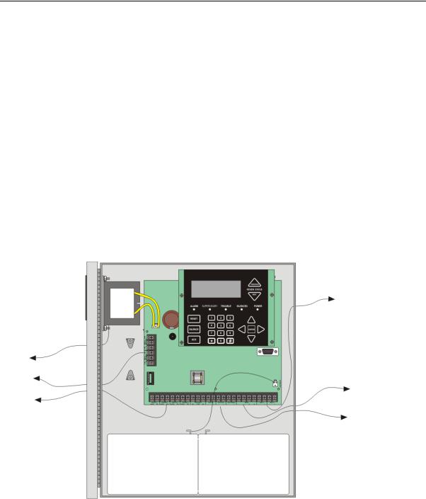
Table 3-1 list the terminal block on the 5700 as well as a description of the each individual terminal and their respective electrical rating. For location of the terminals refer to Figure 3-2. See also Section 4 for installation.
Table 3-1: Terminal Descriptions and Electrical Specifications
Terminal No. |
Label |
Description |
|
Rating |
||
|
|
|
|
|||
Group |
Individual |
Voltage |
Current |
|||
|
|
|||||
|
|
|
|
|
|
|
|
|
|
|
|
|
|
|
|
NO |
Normally open relay contact |
|
|
|
|
RELAY 1 |
|
|
27.4 VDC |
2.5 A, resistive |
|
|
COM |
Common terminal |
||||
|
|
|
|
|
|
|
Terminal Block 1 |
|
NC |
Normally closed relay contact |
|
|
|
|
|
|
|
|
||
|
NO |
Normally open relay contact |
|
|
||
|
|
|
|
|||
|
RELAY 2 |
|
|
27.4 VDC |
2.5 A, resistive |
|
|
COM |
Common terminal |
||||
|
|
|
|
|
|
|
|
|
NC |
Normally closed relay contact |
|
|
|
|
|
|
|
|
|
|
|
TELCO 1 |
RING |
Phone Line 1 Telco Ring |
|
|
|
|
|
|
|
|
||
|
TIP |
Phone Line 1 Telco Tip |
|
|
||
|
|
|
|
|||
|
|
|
|
|
|
|
|
PHONE 1 |
RING |
Phone Line 1 Phone Ring |
|
|
|
|
|
|
|
|
||
|
TIP |
Phone Line 1 Phone Tip |
|
|
||
|
|
|
|
|||
|
|
|
|
|
|
|
|
TELCO 2 |
RING |
Phone Line 2 Telco Ring |
|
|
|
|
|
|
|
|
||
|
TIP |
Phone Line 2 Telco Tip |
|
|
||
|
|
|
|
|||
|
|
|
|
|
|
|
|
PHONE 2 |
RING |
Phone Line 2 Phone Ring |
|
|
|
|
|
|
|
|
||
|
TIP |
Phone Line 2 Phone Tip |
|
|
||
|
|
|
|
|||
|
|
|
|
|
|
|
|
|
NO |
Normally open relay contact |
|
|
|
|
TROUBLE |
|
|
27.4 VDC |
2.5 A, resistive |
|
|
COM |
Common terminal |
||||
|
|
|
|
|
|
|
|
|
NC |
Normally closed relay contact |
|
|
|
|
|
|
|
|
|
|
|
SLC IN |
– |
Used for Class A installations |
32 VDC |
100 mA |
|
Terminal Block 2 |
|
|||||
+ |
||||||
|
|
|
|
|||
|
|
|
|
|
|
|
|
SLC OUT |
– |
SLC terminals |
32 VDC |
100 mA |
|
|
|
|||||
|
+ |
|||||
|
|
|
|
|
||
|
|
|
|
|
|
|
|
SLC PROG |
– |
Used for programming SLC |
32 VDC |
100 mA |
|
|
|
Detectors |
||||
|
+ |
|||||
|
|
|
|
|||
|
|
|
|
|
|
|
|
|
– |
SBUS Power |
27.4 VDC |
0.5 A |
|
|
|
|
||||
|
SBUS |
+ |
||||
|
|
|
|
|||
|
|
|
|
|
||
|
A |
SBUS Communication |
5 VDC |
100 mA |
||
|
|
|||||
|
|
|
||||
|
|
B |
||||
|
|
|
|
|
||
|
|
|
|
|
|
|
|
NAC1* |
– |
Notification Appliance Circuit/ |
27.4 VDC |
2.5 Amp NAC or Aux |
|
|
|
Auxiliary power |
power |
|||
|
+ |
|||||
|
|
|
||||
|
|
|
|
|
|
|
|
NAC2* |
– |
Notification Appliance Circuit/ |
27.4 VDC |
2.5 Amp NAC or Aux |
|
|
|
Auxiliary power |
power |
|||
|
+ |
|||||
|
|
|
||||
|
|
|
|
|
|
|
*Regulated NAC application. When programmed for releasing, NAC are Special Application.
3-2
Model 5700 Installation and Operation Manual |
151295 |
3.4Wiring Specifications
Induced noise (transfer of electrical energy from one wire to another) can interfere with telephone communication or cause false alarms. To avoid induced noise, follow these guidelines:
•Isolate input wiring from high current output and power wiring. Do not pull one multi-conductor cable for the entire panel. Instead, separate the wiring as follows:
High voltage |
AC power Terminals |
|
|
SLC loops |
|
|
|
Audio input/output |
Phone line circuits |
|
|
Notification circuits |
NAC1 through NAC2 |
|
|
SBUS |
|
|
|
Relay circuits |
|
|
|
•Do not pull wires from different groups through the same conduit. If you must run them together, do so for as short a distance as possible or use shielded cable. Connect the shield to earth ground at the panel. You must route high and low voltages separately.
•Route the wiring around the inside perimeter of the cabinet. It should not cross the circuit board where it could induce noise into the sensitive microelectronics or pick up unwanted RF noise from the high speed circuits. See Figure 3-1 for an example.
•High frequency noise, such as that produced by the inductive reactance of a speaker or bell, can also be reduced by running the wire through ferrite shield beads or by wrapping it around a ferrite toroid.
AC Power
Input
Relay
Outputs
Phone
Lines
NAC/Aux Power
Outputs
|
SBUS |
|
Devices |
|
SLC IN/OUT |
|
|
Battery |
Maintain at least 1/4” spacing |
|
between power limited and |
|
non-power limited circuits. |
|
|
Figure 3-1 Wire Routing Example
3-3

Before You Begin Installing |
151295 |
3.5Board Assembly Diagram
On-board
Annunciator
120 VAC,
60 Hz, 1.5A
AC Power
Input |
|
|
|
|
|
Programming |
|
Form C |
|
Port |
|
Relays |
Terminal Block 1 |
|
|
|
|
Battery |
|
Terminal Block 2 |
|
|
Connector |
|
24 VDC |
||
|
|
|
|
|
|
|
|
|
|
|
|
|
|
|
|
Phone |
|
Lines |
|
|
|
SLC |
|
In/Out, |
|
|
|
|
|
|
|
|
|
|
|
|
|
NAC/Aux |
|||||||||
|
|
|
|
|
|
|
|
|
|||||||
|
|
|
|
|
SLC Programming |
|
Power Circuits |
||||||||
|
|
|
|
Form |
C |
|
|
SBUS |
|||||||
|
|
|
Trouble Relay |
Connections |
|||||||||||
Figure 3-2 Model 5700 Assembly
Figure 3-2 shows the circuit boards, and annunciator. If you should need to remove the control board for repair, remove the three mounting screws which hold the control board in the cabinet. Then lift the control board out of the cabinet.
3-4

Model 5700 Installation and Operation Manual |
151295 |
3.6Calculating Current Draw and Standby Battery
This section is for helping you determine the current draw and standby battery needs if you are using SK addressable devices (Table 3-2) or SD addressable devices (Table 3-3).
3.6.1Current Draw Worksheet Requirements
The following steps must be taken when determining 5700 current draw and standby battery requirements.
1.For the 5700, the worst case current draw is listed for the panel, addressable devices, and all SBUS expanders. Fill in the number of addressable devices that will be used in the system and compute the current draw requirements for alarm and standby. Record this information in the Current Calculation Worksheet at Line A.
2.Add up the current draw for all auxiliary devices and record in the table at Line B.
3.Add up all notification appliance loads and record in the table at Line C.
4.For notification appliance circuits and auxiliary devices not mentioned in the manual, refer to the device manual for the current ratings.
5.Make sure that the total alarm current you calculated, including current for the panel itself, does not exceed 2.5 A. This is the maximum alarm current for the 5700 control panel.
If the current is above 2.5 A you will need to use a notification power expander(s) such as the Silent Knight 5496 intelligent power module, to distribute the power loads so that the 5700 or the power expanders do not exceed their power rating. Refer to the current draw worksheets provided with the 5496 manual so you do not exceed their power requirements.
6.Complete the remaining instructions in the Current Calculation Worksheet for determining battery size requirements.
3-5
Before You Begin Installing |
151295 |
3.6.2Current Draw Worksheet for SK SLC Devices
Use Table 3-2 to determine current requirements during alarm/battery standby operation when SK SLC devices are installed. (Copy the page if additional space is required.) You can install up to 50 SK detectors and 50 SK modules.
Table 3-2: Current Calculation Worksheet for SK Devices
Device |
# of |
|
Current per Device |
|
Standby |
Alarm |
||
Devices |
|
|
Current |
Current |
||||
|
|
|
|
|
|
|||
|
|
|
|
|
|
|
|
|
For each device use this formula: |
This column |
X |
This column |
= |
Current |
per number of |
devices. |
|
Fire Panel (Current draw from |
1 |
Standby: |
|
|
|
200 mA |
200 mA |
|
battery) |
Alarm: |
|
|
|
365 mA |
|
365 mA |
|
|
|
|
|
|
||||
Addressable SLC Detectors |
|
|
|
|
|
|
|
|
SK-Photo |
|
|
|
|
|
|
mA |
mA |
|
|
|
|
|
|
|
|
|
SK-Photo-T |
|
|
|
|
|
|
mA |
mA |
|
|
|
|
|
|
|
|
|
SK-Ion |
|
|
|
|
|
|
mA |
mA |
|
|
|
|
|
|
|
|
|
SK-Heat |
|
|
|
|
|
|
mA |
mA |
|
|
|
|
.30 mA6 |
|
|
||
SK-Heat-HT |
|
Standby/Alarm: |
|
mA |
mA |
|||
SK-Acclimate |
(50 max.)1 |
|
|
|
|
|
mA |
mA |
|
|
|
|
|
|
|
|
|
SK-Heat-ROR |
|
|
|
|
|
mA |
mA |
|
|
|
|
|
|
|
|||
|
|
|
|
|
|
|
|
|
SK-DUCT5 |
|
|
|
|
|
|
mA |
mA |
|
|
SLC |
|
Standby/Alarm: |
|
2 mA |
mA |
mA |
SK-Beam (without integral test) |
|
|
|
|
|
|
|
|
|
Aux. Pwr |
Standby: |
|
2 mA |
mA |
|
||
|
|
Alarm: |
|
8.5 mA |
|
mA |
||
|
|
|
|
|
|
|||
|
|
SLC |
|
Standby/Alarm: |
|
2 mA |
|
|
SK-Beam-T4 (with integral test) |
|
|
|
|
|
|
|
|
|
Aux. Pwr |
Standby: |
|
2 mA |
mA |
|
||
|
(50 max.)1 |
Alarm: |
|
8.5 mA |
|
mA |
||
|
|
|
|
|
||||
SK-FIRE-CO |
|
SLC |
|
Standby: |
|
.30 mA |
mA |
|
|
|
Alarm: |
|
7.2 mA |
|
mA |
||
|
|
|
|
|
|
|||
Addressable SLC Modules |
|
|
|
|
|
|
|
|
SK-Monitor |
|
|
|
|
|
|
mA |
mA |
|
|
Standby/Alarm |
|
.375 mA |
|
|
||
SK-Minimon |
|
|
mA |
mA |
||||
|
|
|
|
|
|
|
|
|
SK-Pull-SA/SK-Pull-DA |
|
|
|
|
|
|
|
|
|
|
|
|
|
|
|
||
SK-Monitor-2 |
|
Standby/Alarm: |
|
.75 mA |
mA |
mA |
||
|
|
|
|
|
|
|
||
SK-Mon-10 |
|
Standby/Alarm: |
|
3.5 mA |
mA |
mA |
||
|
|
|
|
|
|
|
|
|
|
|
SLC |
|
Standby: |
|
.375 mA |
mA |
|
SK-Control |
|
|
Alarm: |
|
.375 mA |
|
mA |
|
|
|
|
|
|
||||
|
Aux Pwr |
|
Standby: |
|
1.7 mA |
mA |
|
|
|
|
|
|
|
||||
|
(50 max.)1 |
|
Alarm: |
|
7 mA |
|
mA |
|
|
|
|
|
|
||||
|
|
SLC |
|
Standby: |
|
2.25 mA |
mA |
|
SK-Control-6 |
|
|
Alarm: |
|
2.25 mA |
|
mA |
|
|
|
|
|
|
||||
|
Aux Pwr |
|
Standby: |
|
8 mA |
mA |
|
|
|
|
|
|
|
||||
|
|
|
Alarm: |
|
20 mA |
|
mA |
|
|
|
|
|
|
|
|||
SK-Relay |
|
Standby/Alarm: |
|
|
.255 mA |
mA |
mA |
|
|
|
|
|
|
|
|
||
SK-Relay-6 |
|
Standby/Alarm: |
|
1.45 mA |
mA |
mA |
||
|
|
|
|
|
|
|
|
|
SK-RelayMon-2 |
|
Standby: |
|
|
|
1.3 mA |
mA |
|
|
Alarm: |
|
|
|
24 mA |
|
mA |
|
|
|
|
|
|
|
|||
|
|
|
|
|
|
|
|
|
3-6
Model 5700 Installation and Operation Manual |
|
|
|
151295 |
|
|||
|
Table 3-2: Current Calculation Worksheet for SK Devices |
|
||||||
|
|
|
|
|
|
|
|
|
|
Device |
# of |
|
Current per Device |
|
Standby |
Alarm |
|
|
Devices |
|
|
Current |
Current |
|||
|
|
|
|
|
|
|||
|
|
|
|
|
|
|
|
|
|
|
|
|
|
|
|
|
|
|
|
|
Aux Pwr |
|
Standby: |
12 mA |
mA |
mA |
|
SK-Zone |
|
|
|
|
|
|
|
|
|
|
Alarm: |
90 mA |
mA |
mA |
||
|
|
|
|
|||||
|
|
(50 max.)1 |
|
|
|
|
|
|
|
|
SLC |
|
Standby/Alarm: |
.27 mA |
mA |
mA |
|
|
|
|
Aux Pwr |
|
Standby: |
50 mA |
mA |
mA |
|
SK-Zone-6 |
|
|
|
|
|
|
|
|
|
|
Alarm: |
270 mA |
mA |
mA |
||
|
|
|
|
|||||
|
|
|
|
|
|
|
|
|
|
|
|
SLC |
|
Standby/Alarm: |
2 mA |
mA |
mA |
|
|
|
|
|
|
|
|
|
|
SLC Accessories |
|
|
|
|
|
|
|
|
|
|
Aux Pwr |
|
Standby: |
.50 mA |
mA |
|
|
B200SR Sounder Base |
|
|
Alarm: |
35 mA |
|
mA |
|
|
|
|
|
|
||||
|
|
|
SLC |
|
Standby: |
.3 mA |
mA |
|
|
|
|
Aux |
|
Standby: |
.50 mA |
mA |
|
|
B200S Sounder Base |
|
|
Alarm (high vol) |
35 mA |
|
mA |
|
|
|
|
|
|
||||
|
|
|
SLC |
|
Standby: |
.3mA |
mA |
mA |
|
|
|
|
|
|
|
|
|
|
B200SR-LF Low Frequency |
(50 max.) |
Aux Pwr |
|
Standby: |
1 mA |
mA |
|
|
Sounder Base |
|
|
Alarm: |
125 mA |
|
mA |
|
|
|
|
|
|
||||
|
B200S-LF Low Frequency |
|
Aux Pwr |
|
Standby |
.55 mA |
mA |
|
|
|
|
|
Alarm (high vol) |
140 mA |
|
mA |
|
|
Sounder Base |
|
|
|
|
|||
|
|
|
SLC |
|
Standby |
.30 mA |
mA |
|
|
B224RB Relay Base |
|
Standby/Alarm: |
|
.5 mA |
mA |
mA |
|
|
|
|
|
|
|
|
|
|
|
RTS151/151 KEY |
|
Alarm: |
|
|
7.5 mA |
|
mA |
|
RA100Z |
|
Alarm: |
|
|
10 mA |
|
mA |
|
SLC Isolator Devices |
|
|
|
|
|
|
|
|
SK-Iso (Isolator Module) |
(100 max.) |
Standby/Alarm: |
.45 mA |
mA |
mA |
||
|
|
|
|
|
|
|
||
|
B224BI Isolator Base |
(50 max.) |
Standby/Alarm: |
.5 mA |
|
|
||
|
|
|
|
|
|
|
|
|
|
Accessories Modules |
|
|
|
|
|
|
|
|
5860 Remote Fire Alarm |
(8 max) |
Standby |
|
|
20mA |
mA |
|
|
Annunciator |
Alarm |
|
|
25mA |
|
mA |
|
|
|
|
|
|
||||
|
5824 Serial / Parallel Module |
(2 max.) |
Standby/Alarm: |
|
45 mA |
mA |
mA |
|
|
|
|
|
|
|
|
||
|
5496 Notification Power |
|
Standby/Alarm: |
10 mA |
mA |
mA |
||
|
Expander |
(8 max.) |
|
|
|
|
|
|
|
|
|
|
|
|
|
||
|
5895XL |
|
Standby/Alarm: |
10 mA |
mA |
mA |
||
|
|
|
|
|
|
|
|
|
|
5865-4 LED Annunciator |
|
Standby: |
|
|
35 mA |
mA |
|
|
(with reset and silence switches) |
|
Alarm: |
|
|
145 mA |
|
mA |
|
5865-3 LED Annunciator |
(8 max.) |
Standby: |
|
|
35 mA |
mA |
|
|
Alarm: |
|
|
145 mA |
|
mA |
||
|
|
|
|
|
|
|||
|
5880 Generic LED Driver |
|
Standby: |
|
|
35 mA |
mA |
|
|
Module |
|
Alarm: |
|
|
200 mA |
|
mA |
|
|
|
Standby: |
|
|
0 mA |
mA |
|
|
5883 Relay Interface |
(32 max.) |
Alarm: |
|
|
220 mA |
|
mA |
|
|
|
|
|
(22 mA per relay) |
|
|
|
A |
|
|
|
|
Total System Current |
|
|
|
|
|
|
|
|
|
|
|
|
|
Auxiliary Devices2 |
|
|
Refer to devices manual for current rating. |
|
|||
|
|
|
Alarm/Standby: |
mA |
mA |
mA |
||
|
|
|
|
|
|
|
||
|
|
|
Alarm/Standby: |
mA |
mA |
mA |
||
|
|
|
|
|
|
|
||
|
|
|
Alarm/Standby: |
mA |
mA |
mA |
||
|
|
|
|
|
|
|
||
|
|
|
Alarm/Standby: |
mA |
mA |
mA |
||
|
|
|
|
|
|
|
|
|
3-7
Before You Begin Installing |
|
|
|
|
151295 |
|
|
Table 3-2: Current Calculation Worksheet for SK Devices |
|
||||
|
|
|
|
|
|
|
|
Device |
# of |
|
Current per Device |
Standby |
Alarm |
|
Devices |
|
Current |
Current |
||
|
|
|
|
|||
B |
|
|
|
|
|
|
|
|
|
|
|
|
|
|
|
|
Auxiliary Devices Current |
|
|
|
|
Notification Appliance Circuits |
|
|
Refer to device manual for current |
rating. |
|
|
|
|
Alarm: |
mA |
|
mA |
|
|
|
Alarm: |
mA |
|
mA |
|
|
|
Alarm: |
mA |
|
mA |
C |
|
|
|
Notification Appliances Current |
|
mA |
D |
Total current ratings of all devices in system (line A + line B + C) |
mA |
mA |
|||
E |
|
|
|
|||
Total current ratings converted to amperes (line D x .001): |
A |
A |
||||
F |
|
|
|
|||
Number of standby hours (24 or 60 for NFPA 72, chapter 1, 1-5.2.5): |
H |
|
||||
G |
Multiply lines E and F. |
|
|
Total standby AH |
AH |
|
H |
Alarm sounding period in hours. (For example, 5 minutes = .0833 hours) |
|
H |
|||
I |
Multiply lines E and H. |
|
|
Total alarm AH |
|
AH |
J |
Add lines G and I. 3 |
|
|
Total ampere hours |
AH |
|
|
|
|
required |
|
|
|
|
|
|
|
|
|
|
|
|
|
|
|
|
|
1.Total does not include isolator devices or accessory bases.
2.If using door holders, you do not need to consider door holder current for alarm/battery standby, because power is removed during that time. However, during normal operation, door holders draw current and must be included in the 2.5A total current that can be drawn from the panel.
3.Use next size battery with capacity greater than required.
4.SK-Beam-T draws a maximum of 500mA from auxiliary power only when the test feature is used. This should be considered when determining auxiliary power capacity but not calculated into current requirements for day to day operation.
5.The SK-Duct housing contains a vacant mount for a SK-Relay (sold separately). Current draw for the SK-Relay is calculated by increasing the SK-Relay row of the calculation sheet by one for each SK-Relay used with a SK-Duct.
6.The FACP can only support 5 devices w/LED’s on. This current draw has been added to the panels alarm current.
3.6.3Current Draw Worksheet for SD SLC Devices
Use Table 3-3 to determine current requirements during alarm/battery standby operation when SD SLC devices are installed. (Copy the page if additional space is required).
Table 3-3: Current Calculation Worksheet for SD Devices
Device |
# of |
Current per Device |
Standby |
Alarm |
||
Devices |
Current |
Current |
||||
|
|
|
||||
|
|
|
|
|
|
|
|
|
|
|
|
|
|
For each device use this formula: This column |
X This column |
= Current per number of devices. |
||||
Fire Panel (Current draw from |
1 |
Standby: |
200 mA |
200 mA |
|
|
battery) |
Alarm: |
365 mA |
|
325 mA |
||
|
|
|||||
Addressable SLC Devices |
|
|
|
|
|
|
SD500-AIM |
|
|
|
mA |
mA |
|
|
|
|
|
|
|
|
SD500-MIM |
|
|
|
mA |
mA |
|
|
|
|
|
|
|
|
SD500-ARM |
(50 max.)1 |
|
|
mA |
mA |
|
|
|
.30 mA5 |
|
|
||
SD500-PS/SD500-PSDA |
Standby/Alarm: |
mA |
mA |
|||
|
||||||
SD505-AIS |
|
|
|
|
|
|
|
|
|
|
|
|
|
SD505-AHS |
|
|
|
mA |
mA |
|
|
|
|
|
|
|
|
SD505-APS |
|
|
|
mA |
mA |
|
|
|
|
|
|
|
|
3-8
Model 5700 Installation and Operation Manual |
|
|
151295 |
|
|||
|
Table 3-3: Current Calculation Worksheet for SD Devices |
|
|||||
|
|
|
|
|
|
|
|
|
Device |
# of |
Current per Device |
Standby |
Alarm |
||
|
Devices |
Current |
Current |
||||
|
|
|
|
|
|||
|
|
|
|
|
|
|
|
|
|
|
|
|
|
|
|
|
|
|
Aux. Pwr |
Standby: |
8 mA |
mA |
|
|
SD500-ANM |
(50 max.)1 |
Alarm: |
60 mA |
|
mA |
|
|
|
|
|||||
|
|
|
SLC |
Standby/Alarm: |
.55 mA |
mA |
mA |
|
|
|
|
|
|
|
|
|
|
|
|
Standby: |
10 mA |
mA |
|
|
SD500-LED |
(50 max.)1 |
Aux. Pwr |
Alarm: |
220 mA |
|
mA |
|
|
|
LED: |
10 mA |
mA |
mA |
|
|
|
|
|
||||
|
|
|
|
|
|
|
|
|
|
|
SLC |
Standby/Alarm: |
.55 mA |
mA |
mA |
|
|
|
|
|
|
|
|
|
|
(50 max.)1 |
Aux. Pwr |
Standby: |
20 mA |
mA |
|
|
SD500-SDM |
Alarm: |
106 mA |
|
mA |
||
|
|
|
|
||||
|
|
|
SLC |
Standby/Alarm: |
.55 mA |
mA |
mA |
|
|
|
|
|
|
|
|
|
SLC Accessory Bases |
|
|
|
|
|
|
|
SD505-6RB |
(50 max.) |
Standby/Alarm: |
.082 mA |
mA |
mA |
|
|
|
|
|
|
|
|
|
|
|
|
Aux. Pwr |
Standby: |
1 mA |
mA |
|
|
SD505-6SB |
(50 max.) |
Alarm: |
32 mA |
|
mA |
|
|
|
|
|||||
|
|
|
SLC |
Standby/Alarm |
.082 mA |
mA |
mA |
|
|
|
|
|
|
|
|
|
|
|
Aux. Pwr |
Standby: |
20 mA2 |
mA |
|
|
SD505-DUCTR |
(50 max.) |
Alarm: |
62 mA2 |
|
mA |
|
|
|
|
|||||
|
|
|
SLC |
Standby/Alarm: |
.5 mA |
mA |
mA |
|
|
|
|
|
|
|
|
|
SD505-DTS-K |
(50 max.) |
None, included with SD505-DUCTR worst case. |
|
|||
|
|
|
|
|
|
|
|
|
SD505-DUCT |
(50 max.) |
SLC |
Standby/Alarm: |
.5 mA |
mA |
mA |
|
|
|
|
|
|
|
|
|
SLC Isolator Devices |
|
|
|
|
|
|
|
SD500-LIM |
(100 max.) |
|
|
|
|
|
|
|
|
Standby/Alarm |
.092 mA |
mA |
mA |
|
|
SD505-6IB |
(50 max.) |
|||||
|
|
|
|
|
|
|
|
|
|
|
|
|
|
|
|
|
Accessories Modules |
|
|
|
|
|
|
|
5860 Remote Fire Alarm |
(8 max.) |
Standby: |
|
20 mA |
mA |
|
|
Annunciator |
Alarm: |
|
25 mA |
|
mA |
|
|
|
|
|
||||
|
5824 Serial / Parallel Module |
(2 max.) |
Standby/Alarm: |
45 mA |
mA |
mA |
|
|
|
|
|
|
|
|
|
|
5496 Notification Power |
|
Standby/Alarm: |
10 mA |
mA |
mA |
|
|
Expander |
(8 max.) |
|
|
|
|
|
|
|
|
|
|
|
|
|
|
5895XL Intelligent Power |
Standby/Alarm |
10 mA |
mA |
mA |
||
|
|
||||||
|
Expander |
|
|
|
|
|
|
|
|
|
|
|
|
|
|
|
5865-4 LED Annunciator |
|
Standby: |
|
35 mA |
mA |
|
|
(with reset and silence switches) |
|
Alarm: |
|
145 mA |
|
mA |
|
5865-3 LED Annunciator |
(8 max.) |
Standby: |
|
35 mA |
mA |
|
|
Alarm: |
|
145 mA |
|
mA |
||
|
|
|
|
|
|||
|
5880 Generic LED Driver Module |
|
Standby: |
|
35 mA |
mA |
|
|
|
Alarm: |
|
200 mA |
|
mA |
|
|
|
|
|
|
|||
|
|
|
Standby: |
|
0 mA |
mA |
|
|
5883 Relay Interface |
(32 max.) |
Alarm: |
|
220 mA |
|
mA |
|
|
|
|
(22 mA per relay) |
|
|
|
A |
|
|
|
Total System Current |
|
|
|
|
|
|
|
|
|
|
|
|
Auxiliary Devices3 |
|
Refer to devices manual for current rating. |
|
|||
|
|
|
Alarm/Standby: |
mA |
mA |
mA |
|
|
|
|
|
|
|
|
|
|
|
|
Alarm/Standby: |
mA |
mA |
mA |
|
|
|
|
|
|
|
|
|
|
|
|
Alarm/Standby: |
mA |
mA |
mA |
|
|
|
|
|
|
|
|
|
3-9

Before You Begin Installing |
151295 |
Table 3-3: Current Calculation Worksheet for SD Devices
|
Device |
# of |
|
Current per Device |
Standby |
Alarm |
|
|
Devices |
|
Current |
Current |
|||
|
|
|
|
|
|||
|
|
|
|
|
|
|
|
|
|
|
|
|
|
|
|
|
|
|
Alarm/Standby: |
mA |
mA |
mA |
|
B |
|
|
|
|
|
|
|
|
|
|
Auxiliary Devices Current |
|
|
||
|
|
|
|
|
|
|
|
|
Notification Appliance Circuits |
|
|
Refer to device manual for current rating. |
|
||
|
|
|
Alarm: |
|
mA |
|
mA |
|
|
|
Alarm: |
|
mA |
|
mA |
|
|
|
Alarm: |
|
mA |
|
mA |
|
|
|
Alarm: |
|
mA |
|
mA |
C |
|
|
Notification Appliances Current |
|
mA |
||
D |
Total current ratings of all devices in system (line A + line B + C) |
|
mA |
mA |
|||
E |
|
|
|
|
|
||
Total current ratings converted to amperes (line D x .001): |
|
|
A |
A |
|||
F |
|
|
|
|
|||
Number of standby hours (24 or 60 for NFPA 72, chapter 1, 1-5.2.5): |
|
H |
|
||||
G |
Multiply lines E and F. |
|
|
|
Total standby AH |
AH |
|
H |
Alarm sounding period in hours. (For example, 5 minutes = .0833 hours) |
|
H |
||||
I |
Multiply lines E and H. |
|
|
|
Total alarm AH |
|
AH |
J |
Add lines G and I.4 |
|
|
|
Total ampere hours |
AH |
|
|
|
|
|
required |
|
|
|
|
|
|
|
|
|
|
|
1.Total does not include isolator devices or accessory bases.
2.If using 24 VDC aux power only. No standby or alarm current for battery calculation if using 24 VAC, 120 VAC or 240 VAC.
3.If using door holders, you do not need to consider door holder current for alarm/battery standby, because power is removed during that time. However, during normal operation, door holders draw current and must be included in the 6.0A total current that can be drawn from the panel.
4.Use next size battery with capacity greater than required.
5.The FACP can only support 5 devices w/LED’s on. This current draw has been added to the panels alarm current.
3.6.4Maximum Battery Standby Load
The table below shows the maximum battery standby load for the 5700 based on 24 and 60 hours of standby. The standby load calculations of line D in the Current Draw Calculation Worksheet (Table 3-3) must be less than the number shown in the table below for the battery size used and standby hours required.
Table 3-4 Maximum Battery Standby Load
Rechargeable Battery Size |
Max. Load for 24 hrs. |
*Max. Load for 60 hrs. |
|
Standby, 5 mins. Alarm |
Standby, 5 mins. Alarm |
||
|
|||
|
|
|
|
|
|
|
|
7 AH |
221 mA |
85 mA |
|
|
|
|
|
18 AH |
675 mA |
250 mA |
|
|
|
|
|
35 AH |
1.1 A |
450 mA |
|
|
|
|
*Required for NFPA 72 Auxiliary Protected Fire Alarm systems for Fire Alarm Service (City Box) and Remote Station Protected Fire Alarm systems (Polarity Reversal) and Digital Alarm Communicator/Transmitter (DACT).
Warning!
Silent Knight does not support the use of batteries smaller than those listed in table above. If you use a battery too small for the installation, the system could overload the battery resulting in the installation having less than the required 24 hours standby power. Use the Current Calculation Worksheet to calculate the correct battery amperes/hour rating needed for your installation.
3-10

Model 5700 Installation and Operation Manual |
151295 |
3.7Installation Tasks Overview
This section provides a chart listing tasks that need to be performed when installing the IntelliKnight 5700 system. The chart is intended to be a handy way for you to make sure you have completed all necessary tasks. Unless noted, these tasks do not have to be performed in the order they are listed here.
Important: Connect and address SLC devices before running JumpStart.
Task |
See Sec. |
|
(for more info.) |
||
|
||
|
|
|
|
|
|
Main Panel Hardware Installation |
|
|
|
|
Mount the control panel cabinet. |
4.1 |
|
|
Connect AC. |
4.2 |
|
|
Connect phone lines. |
4.10 |
|
|
Install 5860 Remote Fire Alarm Annunciator modules if used. |
4.5 |
|
|
Install 5865 or LED Annunciator modules if used. |
4.8 |
|
|
Install 5880 LED I/O module if customized LED annunciation will be used. |
4.7 |
|
|
Install notification appliances. |
4.11 |
|
|
Install auxiliary power devices (if used). |
4.11.2 |
|
|
If using a printer, install the 5824 Serial/Parallel Printer Interface Module. |
4.6 |
|
|
Connect batteries (typically last step). |
4.3 |
|
|
SLC Device Hardware Installation. Perform these steps before running JumpStart. |
|
|
|
Connect device bases to the loop. |
SK 5.5 |
|
SD 5.7 |
|
|
Set device addresses. |
SK 5.6 |
|
SD 5.7 |
|
|
Physically connect detectors to their bases. Connect relay and contact monitor modules. |
5.4 & see device |
|
install instructions |
|
|
JumpStart |
|
|
|
JumpStart is for initial system programming. JumpStart automatically selects some options for SLC |
6.1 & 7.7 |
devices. See “Input Point Configuration” section of this chart for other options. |
|
JumpStart makes selections for the following options. You can customize options, if necessary. |
|
|
|
Device type (detector or switch) configured by JumpStart. |
To change, see 7.5 |
|
|
Program type of detector (heat, photoelectric, or ionization) selected by JumpStart. |
To change, see 7.5 |
|
|
System Software Configuration |
|
|
|
Select low AC hours report time (3 hours by default). |
7.6.6.3 |
|
|
Select Auto Test Time (2:00 AM by default). |
7.6.1.2 |
|
|
Enable/disable automatic DST adjustment feature (enabled by default). |
7.6.6.4 |
|
|
Change clock display format (12-hour with AM/PM by default). |
7.6.6.4 |
|
|
Set up reporting accounts. |
7.6.1 |
|
|
Select options for phone lines. |
7.6.2 |
|
|
Select system-wide response to trouble conditions, if desired. |
7.6.3 |
|
|
Select system-wide cadence patterns for special conditions (fire drill, Aux1 and Aux2 alarms) |
7.6.3.2 |
if desired. |
|
|
|
Customize banner message (message that displays on LCD in normal mode) if desired. |
7.6.9 |
|
|
Input Point (SLC Device) Configuration
3-11

Before You Begin Installing |
151295 |
Task |
See Sec. |
|
(for more info.) |
||
|
||
|
|
JumpStart automatically selects some options for SLC devices (see “JumpStart” section of this chart). You can change options selected by JumpStart, if necessary and further customize input point options.
Select device type SK or SD). Only one device type can be used per control panel. |
7.2 |
|
|
Program type of switch (manual pull, fire drill, and so on), if necessary. (JumpStart assigns all |
7.5 |
switches as Manual Pull type.) |
|
|
|
If the installation includes duct detectors, program detector type. (JumpStart does not |
7.5 |
distinguish duct detectors from ordinary smoke detectors.) |
|
|
|
Assign a name (or description) to the point. |
7.5.4 |
|
|
Assign input points to zones, if necessary. (JumpStart assigns all input points to Zone 1.) |
7.5.4 |
|
|
Zone Configuration |
|
|
|
Add the zone to the system if it does not already exist. (Zone 1 created by JumpStart.) |
7.3.2 |
|
|
Program a name (or description) for the zone. |
7.3.1.1 |
|
|
Select alarm delay options (detection characteristics) for zone. |
7.3.1.1 |
|
|
Select heat detector trip temperature and/or. (JumpStart selects 150°F for heat detectors and |
7.3.1.2 |
Low.) |
|
|
|
Output Point Configuration |
|
|
|
Conventional notification circuits (circuits 1-6): |
|
|
|
Enable circuits used for notification appliances through programming, if necessary. |
7.4.1 |
(JumpStart enables circuits 1-6 as Notification.) |
|
|
|
Conventional relay circuits (circuits 7-8): |
|
|
|
Select options for relay circuits, if desired. Note: Relay circuits will always output continuously |
7.4.1 |
(constant pattern), even if assigned to an Output Group that uses a different output pattern. |
|
|
|
Auxiliary power circuits (circuits 1-6): |
|
|
|
Enable any circuit used for auxiliary power devices through programming. |
7.5 |
|
|
Select type of power (door holder, constant, or re-settable) |
7.5 |
|
|
Addressable relay modules |
|
|
|
Assign addressable relay modules to output groups through programming. (JumpStart |
7.5 |
assigns all relay modules to Group 1.) |
|
|
|
LED output points (from the 5880 LED I/O module or 5865/66 LED Annunciator) |
|
|
|
Assign LED modules to output groups through programming. |
7.5.3 |
|
|
All output circuits (1-8): |
|
|
|
Disable (set to UNUSED) any unused circuits. If you do not disable unused output circuits, |
7.5 |
they will cause a trouble condition (unless an EOL resistor is used). |
|
|
|
Select a name for the point, if desired. |
7.5.4 |
|
|
Output Group Configuration |
|
|
|
Add the group to the system if it does not already exist. |
7.4.2 |
|
|
Assign output points to the group. |
7.5 |
|
|
Program a name (or description) for the group, if desired. |
7.4.1.1 |
|
|
Select “group properties” (see below). |
|
|
|
Latching / non-latching |
7.4.1.2 |
|
|
Silencing option |
7.4.1.2 |
|
|
Select options for activation with system switches. |
7.4.1.2 |
|
|
Map zones to output groups that will activate when zone goes into alarm. |
7.3.1.3 |
|
|
Select a cadence pattern for outputs in the zone. |
7.3.1.4 |
|
|
3-12

151295
Section 4
Control Panel Installation
Caution!
To avoid the risk of electrical shock and damage to the unit, power should be OFF at the control panel while installing or servicing.
4.1Mounting the Control Panel Cabinet
Read the environmental specifications in Section 3.2 before mounting the 5700 panel.
The 5700 cabinet dimensions are: 12¾” W x 15-1/8” H x 3-3/8” D (32.39 cm W x 38.42 cm H x 8.57 cm D).
The 5700 panel should be located within a secured area, where it is accessible to main drop wiring runs and where it can be easily tested and serviced. End-users responsible for maintaining the panel should be able to hear alarms and troubles. When selecting a location, keep in mind that the panel itself is the main source of alarm and trouble annunciation.
When mounting on interior walls, use appropriate screw anchors in plaster. When mounting on concrete, especially when moisture is expected, attach a piece of 3/4 inch plywood to the concrete surface and then attach the 5700 to the plywood. Also mount any other desired components to the plywood.
DO NOT flush-mount the 5700 cabinet in a wall designated as a fire break.
4.1.1Preventing Water Damage
Water damage to the fire system can be caused by moisture entering the cabinet through the conduits. Conduits that are installed to enter the top of the cabinet are most likely to cause water problems. Installers should take reasonable precautions to prevent water from entering the cabinet. Water damage is not covered under warranty.
4.1.2Removing the 5700 Assembly from the Housing
If it should ever be necessary to remove the control panel assembly from the cabinet for repair, do so by removing the screws that hold the control panel in to the cabinet. Do not attempt to disassemble the circuit boards.
4.1.3Dead Front Installation and removal
This section provides instructions to install and or remove the optional dead front (DF-50) for the control panel cabinet.
4-1
Loading...