


 Loading...
Model
SK-5208
Fire Control / Communicator
Installation and
Operations Manual
Document 151204
05/15/2014 |
Rev: M |
P/N 151204:M |
ECN: 14-0068 |
|
|

Installation Procedure
Adherence to the following will aid in problem-free installation with long-term reliability:
Installation Precautions - Adherence to the following will aid in problem-free installation with long-term reliability: WARNING - Several different sources of power can be connected to the fire alarm control panel. Disconnect all sources of power before servicing. Control unit and associated equipment may be damaged by removing and/or inserting cards, modules, or interconnecting cables while the unit is energized. Do not attempt to install, service, or operate this unit until manuals are read and understood. CAUTION - System Re-acceptance Test after Software Changes: To ensure proper system operation, this product must be tested in accordance with NFPA 72 after any programming operation or change in site-specific software. Re-acceptance testing is required after any change, addition or deletion of system components, or after any modification, repair or adjustment to system hardware or wiring. All components, circuits, system operations, or software functions known to be affected by a change must be 100% tested. In addition, to ensure that other operations are not inadvertently affected, at least 10% of initiating devices that are not directly affected by the change, up to a maximum of 50 devices, must also be tested and proper system operation verified. This system meets NFPA requirements for operation within the range of 0°C-49°C (32°F-120°F) or humidity within the range of 10%-93% at 30°C (86°F) noncondensing. However, the useful life of the system's standby batteries and the electronic components may be adversely affected by extreme temperature ranges and humidity. Therefore, it is recommended that this system and its peripherals be installed in an environment with a normal room temperature of 15-27º C/60-80º F. Verify that wire sizes are adequate for all initiating and indicating device loops. Most devices cannot tolerate more than a 10% I.R. drop from the specified device voltage. Like all solid state electronic devices, this system may operate erratically or can be damaged when subjected to lightning induced transients. Although no system is completely immune from lightning transients and interference, proper grounding will reduce susceptibility. Overhead or outside aerial wiring is not recommended, due to an increased susceptibility to nearby lightning strikes. Consult with the Technical Services Department if any problems are anticipated or encountered. Disconnect AC power and batteries prior to removing or inserting circuit boards. Failure to do so can damage circuits. Remove all electronic assemblies prior to any drilling, filing, reaming, or punching of the enclosure. When possible, make all cable entries from the sides or rear. Before making modifications, verify that they will not interfere with battery, transformer, or printed circuit board location. Do not tighten screw terminals more than 9 in-lbs. Over-tightening may damage threads, resulting in reduced terminal contact pressure and difficulty with screw terminal removal. fire alarm control panels contain static-sensitive components. Always ground yourself with a proper wrist strap before handling any circuits so that static charges are removed from the body. Use static suppressive packaging to protect electronic assemblies removed from the unit.
Follow the instructions in the installation, operating, and programming manuals. These instructions must be followed to avoid damage to the control panel and associated equipment. Fire Alarm Control Panel (FACP) operation and reliability depend upon proper installation.
While installing a fire alarm system may make lower insurance rates possible, it is not a substitute for fire insurance! An automatic fire alarm system - typically made up of smoke detectors, heat detectors, manual pull stations, audible warning devices, and a fire alarm control with remote notification capability - can provide early warning of a developing fire. Such a system, however, does not assure protection against property damage or loss of life resulting from a fire. Any fire alarm system may fail for a variety of reasons: Smoke detectors may not sense fire where smoke cannot reach the detectors such as in chimneys, in walls, or roofs, or on the other side of closed doors. Smoke detectors also may not sense a fire on another level or floor of a building. A second floor detector, for example, may not sense a first floor or basement fire. Furthermore, all types of smoke detectors, including ionization and photoelectric types, have sensing limitations. No type of smoke detector can sense every kind of fire caused by carelessness and safety hazards like smoking in bed, violent explosions, escaping gas, improper storage of flammable materials, overloaded electrical circuits, children playing with matches, or arson.
IMPORTANT! Smoke detectors must be installed in the same room as the control panel and in rooms used by the system for the connection of alarm transmission wiring, communications, signaling, and/or power. If detectors are not so located, a developing fire may damage the alarm system, crippling its ability to report a fire. Audible warning devices such as bells may not alert people if these devices are located on the other side of closed or partly open doors or are located on another floor of a building. A fire alarm system will not operate without any electrical power. If AC power fails, the system will operate from standby batteries only for a specified time. Rate-of-Rise heat detectors may be subject to reduced sensitivity over time. For this reason, the rate-of-rise feature of each detector should be tested at least once per year by a qualified fire protection specialist. Equipment used in the system may not be technically compatible with the control. It is essential to use only equipment listed for service with your control panel. Telephone lines needed to transmit alarm signals from a premise to a central monitoring station may be out of service or temporarily disabled. The most common cause of fire alarm malfunctions, however, is inadequate maintenance. All devices and system wiring should be tested and maintained by professional fire alarm installers following written procedures supplied with each device. System inspection and testing should be scheduled monthly or as required by national and/or local fire codes. Adequate written records of all inspections should be kept.

Contents
Contents
Section 1 |
|
||
Introduction .............................................................................................................................................. |
1-1 |
||
1.1 |
Model SK-5208 Features ......................................................................................................................... |
1-1 |
|
1.2 |
About This Manual .................................................................................................................................. |
1-1 |
|
1.3 |
How to Contact Silent Knight .................................................................................................................. |
1-1 |
|
|
1.3.1 |
Optional Accessories ...................................................................................................................... |
1-2 |
Section 2 |
|
||
Agency Listings and Requirements ........................................................................ |
1-1 |
||
2.1 |
Federal Communications Commission (FCC) ......................................................................................... |
1-1 |
|
2.2 |
Underwriters Laboratories (UL) .............................................................................................................. |
1-1 |
|
|
2.2.1 Requirements for All Installations .................................................................................................... |
1-2 |
|
|
2.2.2 Requirements for Central Station Fire Alarm Systems .................................................................... |
1-2 |
|
|
2.2.3 Requirements for Auxiliary Protected Fire Alarm Systems for Fire Alarm Service ........................ |
1-2 |
|
|
2.2.4 Requirements for Remote Station Protected Fire Alarm Systems, for Digital Communication or |
|
|
|
|
Polarity Reversal ............................................................................................................................... |
1-2 |
Section 3 |
|
||
Control Panel Installation ...................................................................................................... |
1-1 |
||
3.1 |
Electrical Specifications ........................................................................................................................... |
1-1 |
|
3.2 |
Environmental Specifications .................................................................................................................. |
1-1 |
|
3.3 |
Wiring Specifications ............................................................................................................................... |
1-1 |
|
3.4 |
Control Board Components ..................................................................................................................... |
1-3 |
|
3.5 |
Mounting the SK-5208 ............................................................................................................................. |
1-4 |
|
|
3.5.1 |
Preventing Water Damage ................................................................................................................ |
1-4 |
3.6 |
Current Draw Calculations ....................................................................................................................... |
1-4 |
|
|
3.6.1 |
Worksheet Requirements .................................................................................................................. |
1-4 |
|
3.6.2 |
Current Draw Worksheet .................................................................................................................. |
1-5 |
|
3.6.3 Maximum Battery Standby Load ...................................................................................................... |
1-6 |
|
3.7 |
AC Wiring ................................................................................................................................................ |
1-6 |
|
3.8 |
Backup Batteries ...................................................................................................................................... |
1-7 |
|
3.9 |
Terminal Strip Description ....................................................................................................................... |
1-8 |
|
3.10 |
Telephone Line Connection .................................................................................................................. |
1-10 |
|
3.11 |
Detector Installation ............................................................................................................................... |
1-10 |
|
|
3.11.1 Class A (Style D) Zones ................................................................................................................. |
1-10 |
|
|
3.11.2 Class B (Style B) Zones ................................................................................................................. |
1-11 |
|
|
3.11.3 Four-Wire Smoke Detector Connection ......................................................................................... |
1-12 |
|
|
3.11.4 Two-Wire Smoke Detector Connection ......................................................................................... |
1-13 |
|
3.12 Supervised Notification Appliance Outputs ......................................................................................... |
1-13 |
||
3.13 |
Auxiliary Relays .................................................................................................................................... |
1-15 |
|
3.14 |
Accessory Devices ................................................................................................................................. |
1-15 |
|
|
3.14.1 Setting ID Codes ............................................................................................................................. |
1-15 |
|
1

Installation Manual |
|
|
||
|
3.14.2 Model SK-5235 Remote Annunciator ............................................................................................ |
1-16 |
||
|
3.14.2.1 Mounting the SK-5235 Remote Annunciator ...................................................................... |
1-16 |
||
|
3.14.2.2 Wiring the SK-5235 ............................................................................................................. |
1-17 |
||
|
3.14.3 Model SK-5280 Status Display Module ......................................................................................... |
1-18 |
||
|
3.14.3.1 Mounting the SK-5280 ......................................................................................................... |
1-19 |
||
|
3.14.3.2 Wiring Relays ...................................................................................................................... |
1-20 |
||
|
3.14.3.3 Wiring LEDs to Outputs ...................................................................................................... |
1-21 |
||
|
3.14.4 Model SK-5217 Zone Expander Installation .................................................................................. |
1-22 |
||
|
3.14.4.1 Zone Inputs .......................................................................................................................... |
1-22 |
||
|
3.14.4.2 Mounting Instructions .......................................................................................................... |
1-24 |
||
|
3.14.5 Model 5824 Installation Instructions .............................................................................................. |
1-25 |
||
|
3.14.5.1 Mounting the 5824 Module .................................................................................................. |
1-25 |
||
|
3.14.5.2 5824 SBUS Connections ...................................................................................................... |
1-26 |
||
3.15 |
Special Applications .............................................................................................................................. |
1-27 |
||
|
3.15.1 Model 5220 Direct Connect Module .............................................................................................. |
1-27 |
||
|
3.15.1.1 City Box Connection ............................................................................................................ |
1-27 |
||
|
3.15.1.2 NFPA 72 Polarity Reversal .................................................................................................. |
1-28 |
||
|
3.15.2 Keltron 95M3158 Tones Transmitter Module ................................................................................ |
1-29 |
||
|
3.15.3 Using a MR-201/T Control Relay From Air Products ................................................................... |
1-30 |
||
Section 4 |
|
|
||
Programming ......................................................................................................................................... |
1-1 |
|||
4.1 Keypad Operation During Programming ................................................................................................. |
1-1 |
|||
|
4.1.1 |
Special Characters ............................................................................................................................. |
1-2 |
|
|
4.1.2 Enabling Extended Programming List .............................................................................................. |
1-2 |
||
4.2 |
Programming Flow .................................................................................................................................. |
1-3 |
||
|
4.2.1 |
Zone Options ..................................................................................................................................... |
1-4 |
|
|
4.2.2 |
Misc System Option .......................................................................................................................... |
1-5 |
|
|
4.2.3 |
NAC Cadence ................................................................................................................................... |
1-6 |
|
|
4.2.3.1 |
Cadence Patterns .................................................................................................................... |
1-6 |
|
|
4.2.4 |
NAC Options .................................................................................................................................... |
1-7 |
|
|
4.2.5 |
Relay Options ................................................................................................................................... |
1-8 |
|
|
4.2.6 |
User Code ......................................................................................................................................... |
1-9 |
|
|
4.2.7 |
Account ........................................................................................................................................... |
1-10 |
|
|
4.2.8 |
Computer Options ........................................................................................................................... |
1-11 |
|
|
4.2.8.1 |
Computer Code .................................................................................................................... |
1-11 |
|
|
4.2.9 |
Line Options ................................................................................................................................... |
1-12 |
|
|
4.2.10 Misc Reporting ............................................................................................................................... |
1-13 |
||
|
4.2.11 |
5280 Outputs ................................................................................................................................... |
1-14 |
|
|
4.2.12 |
5824 Expander Options .................................................................................................................. |
1-15 |
|
|
4.2.13 DST/Clk Options ............................................................................................................................ |
1-16 |
||
4.3 |
Programming Options ............................................................................................................................ |
1-17 |
||
Section 5 |
|
|
||
Operation ..................................................................................................................................................... |
|
1-1 |
||
5.1 Installer & User Keys ............................................................................................................................... |
1-1 |
|||
5.2 On-board Touchpad and SK-5235 Operation .......................................................................................... |
1-2 |
|||
|
5.2.1 View Control Panel Firmware Number and Revision ...................................................................... |
1-2 |
||
5.3 |
Acknowledge Operation .......................................................................................................................... |
1-3 |
||
2

|
|
|
Contents |
5.4 |
LED Indicators ......................................................................................................................................... |
1-3 |
|
5.5 |
Releasing Operation ................................................................................................................................. |
1-4 |
|
|
5.5.1 |
Cross Alarm Operation ..................................................................................................................... |
1-4 |
|
5.5.1.1 Default NAC Settings for Releasing ...................................................................................... |
1-4 |
|
|
5.5.2 Double Interlock Releasing Operation ............................................................................................. |
1-6 |
|
5.6 |
Smoke Alarm Verification ....................................................................................................................... |
1-6 |
|
5.7 |
System Testing ......................................................................................................................................... |
1-7 |
|
|
5.7.1 |
Fire Drills .......................................................................................................................................... |
1-7 |
|
5.7.2 |
Walk Test .......................................................................................................................................... |
1-7 |
|
5.7.3 |
Automatic Self Test .......................................................................................................................... |
1-7 |
|
5.7.4 |
Watchdog Circuit .............................................................................................................................. |
1-7 |
5.8 |
Communicating with a Programming Computer ..................................................................................... |
1-7 |
|
|
5.8.1 Programming From a Remote Computer Location .......................................................................... |
1-8 |
|
|
5.8.1.1 Having the Control Panel Call the Remote Computer ........................................................... |
1-8 |
|
|
5.8.1.2 Having Remote Computer Call the Control Panel ................................................................. |
1-8 |
|
|
5.8.2 Directly Connecting to a Programming Computer ........................................................................... |
1-9 |
|
Section 6 |
|
||
Reporting ..................................................................................................................................................... |
1-1 |
||
6.1 |
Reporting Formats .................................................................................................................................... |
1-1 |
|
6.2 |
Reporting Codes ....................................................................................................................................... |
1-2 |
|
|
6.2.1 Default Settings for 3/1 Format ........................................................................................................ |
1-5 |
|
Section 7 |
|
||
Troubleshooting ................................................................................................................................ |
1-1 |
||
7.1 |
System Error Messages ............................................................................................................................ |
1-1 |
|
7.2 |
Earth Ground Fault Troubleshooting ....................................................................................................... |
1-2 |
|
7.3 |
Earth Fault Resistance .............................................................................................................................. |
1-3 |
|
Appendix A |
|
||
Compatible Devices ..................................................................................................................... |
A-1 |
||
Silent Knight Fire Product Warranty and Return Policy
Manufacturer Warranties and Limitation of Liability Model SK5208 Basic Operating Instructions
3

151204
Section 1
Introduction
The Model SK-5208 is an 24-volt 10-zone fire alarm control panel (expandable up to 30 zones using SK-5217 Zone Expanders) with a digital communicator that meets NFPA 72 requirements. The SK-5208 cabinet can be surface mounted or semi-flush mounted.
1.1Model SK-5208 Features
•Built-in two-line (16 Character each line) LCD display provides easy to read English language readouts
•10 Initiation inputs, 8 Class B (Style B) and 2 zones that can be configured as Class B (Style B) or Class A (Style D), expandable to 30 zones
•Supervised zone expanders and I/O modules can be mounted remotely from the main control panel
•UL Listed
•Event History Buffer (approximately 150 events) with Date/Time stamp
•All zones are compatible with 2- and 4-wire detectors
•8 selectable/programmable output pattern for notification appliance circuits (Including ANSI 3.41)
•Built-in Digital Alarm Communicator Transmitter (DACT)
•4 Notification appliance circuits
•4 programmable general purpose relays
•Programmable smoke verification, pre-alarm delay, cross zoning and enhanced verification mode features that can help minimize false alarms
•Capable of single or dual operation for water releasing services.
•Programmable from the built-in control panel touchpad, remote annunciator or Windows® downloading software
•Built-in walk test
1.2About This Manual
This manual is intended to be a complete reference for all installation and operation tasks for the SK-5208. Please let us know if the manual does not meet your needs in any way. We value your feedback!
1.3How to Contact Silent Knight
If you have a question or encounter a problem not covered in this manual, contact Silent Knight Technical Support at 800-446-6444.
To order parts, contact Silent Knight Sales at 800-328-0103.
1-1
Model SK-5208 Installation Manual |
151204 |
1.3.1Optional Accessories
Table 1-1: Compatible Modules Manufactured by Silent Knight
Model |
What It Does |
|
|
|
|
SK-5217 Zone Expander |
Adds 10 zones to the SK-5208 for a total expansion of the system to 30 zones. |
|
|
SK-2190 Accessory Cabinet |
Used for remote mounting of the SK-5217 Zone Expander. |
|
Dimensions: 10-3/8”W x 10-3/16”H x 3”D (26.35 cm W x 25.88 cm H x 7.62 cm D) |
|
|
5220 Direct Connect Module |
For direct alarming and trouble transmission from the SK-5208 to a supervising |
|
station. |
|
|
SK-5235 Remote Annunciator |
For remote annunciation, operation, and on-site programming. |
|
|
SK-5280 |
The Model SK-5280 Status Display module provides outputs and control functions for |
|
remote annunciation of alarm, trouble, and supervisories for each zone. |
|
|
5824 |
Provides connectivity to a Serial or Parallel printer. (See Section 4.2.12 for |
|
programming.) |
|
|
SK-5499 Signal Power Expander |
Notification circuit power for additional notification appliances. Provides additional |
|
9A of 24 VDC, supervised. |
|
|
SK-5495 Signal Power Expander |
Notification circuit power for additional notification appliances. Provides additional |
|
6A of 24 VDC, supervised. |
|
|
SKSS Downloading Software |
For remote programming of the SK-5208 using a personal computer. |
Model 5660 |
|
|
|
PLEX-2 |
Optional door accessory for single button operation. (See Section 4.3 for |
|
programming.) |
|
|
Limitations of Fire Alarm Systems
Manufacturer recommends that smoke and/or heat detectors be located throughout a protected premise following the recommendations of the current edition of the National Fire Protection Association Standard 72 (NFPA 72), manufacturer’s recommendations, State and local codes, and the recommendations contained in Guide for the Proper Use of System Smoke Detectors, which is made available at no charge to all installing dealers. A study by the Federal Emergency Management Agency (an agency of the United States government) indicated that smoke detectors may not go off or give early warning in as many as 35% of all fires. While fire alarm systems are designed to provide warning against fire, they do not guarantee warning or protection against fire. A fire alarm system may not provide timely or adequate warning, or simply may not function, for a variety of reasons. For example:
•Particles of combustion or smoke from a developing fire may not reach the sensing chambers of smoke detectors because:
-Barriers such as closed or partially closed doors, walls, or chimneys may inhibit particle or smoke flow.
-Smoke particles may become cold, stratify, and not reach the ceiling or upper walls where detectors are located.
-Smoke particles may be blown away from detectors by air outlets
-Smoke particles may be drawn into air returns before reaching the detector.
In general, smoke detectors on one level of a structure cannot be expected to sense fires developing on another level.
•The amount of smoke present may be insufficient to alarm smoke detectors. Smoke detectors are designed to alarm at various levels of smoke density. If such density levels are not created by a developing fire at the location of detectors, the detectors will not go into alarm.
•Smoke detectors, even when working properly, have sensing limitations. Detectors that have photoelectronic sensing chambers tend to detect smoldering fires better than flaming fires, which have little visible smoke. Detectors that have ionizing-type sensing chambers tend to detect fast flaming fires better than smoldering
1-2
Introduction |
151204 |
fires. Because fires develop in different ways and are often unpredictable in their growth, neither type of detector is necessarily best and a given type of detector may not provide adequate warning of a fire.
•Smoke detectors are subject to false alarms and nuisance alarms and may have been disconnected by users. For example, a smoke detector located in or near a kitchen may go into nuisance alarm during normal operation of kitchen appliances. In addition, dusty or steamy environments may cause a smoke detector to falsely alarm. If the location of a smoke detector causes an abundance of false alarms or nuisance alarms, do not disconnect the smoke detector; call a professional to analyze the situation and recommend a solution.
•Smoke detectors cannot be expected to provide adequate warning of fires caused by arson, children playing with matches (especially within bedrooms), smoking in bed, violent explosions (caused by escaping gas, improper storage of flammable materials, etc.).
•Heat detectors do not sense particles of combustion and are designed to alarm only when heat on their sensors increases at a predetermined rate or reaches a predetermined level. Heat detectors are designed to protect property, not life.
•Warning devices (including horns, sirens, and bells) may not alert people or wake up sleepers who are located on the other side of closed or partially open doors. A warning device that activates on a different floor or level of a dwelling or structure is less likely to awaken or alert people. Even persons who are awake may not notice the warning if the alarm is muffled by noise from a stereo, radio, air conditioner or other appliance, or by passing traffic. Audible warning devices may not alert the hearing-impaired (strobes or other devices should be provided to warn these people). Any warning device may fail to alert people with a disability, deep sleepers, people who have recently used alcohol or drugs, or people on medication or sleeping pills.
-Please note that:
i)Strobes can, under certain circumstances, cause seizures in people with conditions such as epilepsy.
ii)Studies have shown that certain people, even when they hear a fire alarm signal, do not respond or comprehend the meaning of the signal. It is the property owner’s responsibility to conduct fire drills and other training exercises to make people aware of fire alarm signals and instruct on the proper reaction to alarm signals.
iii)In rare instances, the sounding of a warning device can cause temporary or permanent hearing loss.
•Telephone lines needed to transmit alarm signals from a premises to a central station may be out of service or temporarily out of service. For added protection against telephone line failure, backup radio transmission systems are recommended.
•System components, though designed to last many years, can fail at any time. As a precautionary measure, it is recommended that smoke detectors be checked, maintained, and replaced per manufacturer's recommendations.
•System components will not work without electrical power. If system batteries are not serviced or replaced regularly, they may not provide battery backup when AC power fails.
•Environments with high air velocity or that are dusty or dirty require more frequent maintenance.
In general, fire alarm systems and devices will not work without power and will not function properly unless they are maintained and tested regularly.
While installing a fire alarm system may make the owner eligible for a lower insurance rate, an alarm system is not a substitute for insurance. Property owners should continue to act prudently in protecting the premises and the people in their premises and should properly insure life and property and buy sufficient amounts of liability insurance to meet their needs.
1-3

151204
Section 2
Agency Listings and Requirements
Install and maintain in accordance with NFPA 72. Detector spacing shall be in accordance to NFPA 72. End-of - line relays and resistors shall be placed within the electrical box located and the end of the initiating circuit. Testing and maintenance should be performed according to NFPA 72.
2.1Federal Communications Commission (FCC)
1.If requested by the telephone company, the following information must be provided before the SK-5208 can be connected to the phone lines:
A. |
Manufacturer: |
Silent Knight |
A. |
Model Number: |
SK-5208 |
B. |
FCC registration number: |
AC6USA-34758-AL-E |
|
Ringer equivalence: |
0.5B |
C. |
Type of jack (to be installed by the telephone company): |
RJ31X |
2.This device may not be directly connected to coin telephone or party line services.
3.This device cannot be adjusted or repaired in the field. In case of trouble with the device, notify the installing company or return to:
Silent Knight
12 Clintonville Road Northford, CT 06472-1610 203-484-7161 or 800-328-0103
4.If the SK-5208 causes harm to the telephone network, the telephone company will notify the user in advance that temporary discontinuance of service may be required. When advance notice is not practical, the telephone company will notify the user as soon as possible. Users have the right to file complaints, if necessary, with the Federal Communications Commission.
5.The telephone company may make changes in its facilities, equipment, operations, or procedures that could affect the operation of the equipment. If this happens, the telephone company will provide advance notice to allow you to make the necessary modifications to maintain uninterrupted service.
Warning
This device has been verified to comply with FCC Rules Part 15. Operation is subject to the two following conditions: (1) This device may not cause radio interference; and (2) This device must accept any interference received including interference that may cause undesired operation.
2.2Underwriters Laboratories (UL)
The SK-5208 is UL Listed as a control unit for use in Central Station Protected Premises, Local Protected Fire Alarm Systems, Auxiliary Protected Fire Alarm Systems for Fire Alarm Service (City Box), Remote Station Protected Fire Alarm Systems and water releasing service. If the SK-5208 and its accessories are to be used as part of a UL installation, carefully read the UL requirements in this section.
2-1
Agency Listings and Requirements |
151204 |
2.2.1Requirements for All Installations
General requirements are described below. The sections that follow describe additional requirements for the type of installation (for example, Central Station Fire Alarm systems, Local Protected Fire Alarm systems, and so on).
1.Use UL listed smoke detectors compatible with the SK-5208. Refer to Appendix A.
2.Use UL listed compatible notification devices. Refer to Appendix A.
Restricted Options:
•The loss of AC signal is defaulted to 3 hours however the system allows settings from 0 - 30 hours. For UL certified installations this number must be set from 1 to 3 hours.
•Call forwarding shall not be used.
•When cross zoning is used detector spacing shall be cut in half, you shall not use the alarm verification feature, and no delay shall be used.
2.2.2Requirements for Central Station Fire Alarm Systems
1.The Phone Line “Line Dial Type” must be selected for anything other than “Not Used”. (See programming Section 4.2.9).
2.On class A (style D) zones, the number of waterflow devices is limited to five.
3.Auxiliary relays may not be programmed to activate for Pre-Alarm. See programming Section 4.2.5.
2.2.3Requirements for Auxiliary Protected Fire Alarm Systems for Fire Alarm Service
1.Follow the current load restrictions shown in Section 3.6.
2.The Model 5220 Direct Connect module must be installed (see Section 3.15.1 for wiring).
2.2.4Requirements for Remote Station Protected Fire Alarm Systems, for Digital Communication or Polarity Reversal
1.Follow the current load restrictions shown in Section 3.6.
2.Use the SK-5208’s built-in dialer or install the Model 5220 Direct Connect Module (see Section 3.15.1).
2-2
151204
Section 3
Control Panel Installation
3.1Electrical Specifications
Table 3-1: Electrical Specifications
Primary AC |
120 Vrms at 60 Hz, 3A |
Total DC Load |
6A |
Accessory Power |
27.4 VDC, 1A |
Smoke Power |
27.4 VDC, 1A |
Battery Charging Voltage |
27.4 |
Battery Charging Current |
.75 A max. |
Class B (Style B) Circuit Current |
95 mA max. |
Telephone Minimum Input Sensitivity |
35 dB |
Good Phone Line Voltage |
3 V |
Maximum Low Battery Detect |
20.4 |
Minimum Low AC Detect |
98 |
Notification Power |
3A max. per output (6A total) |
3.2Environmental Specifications
It is important to protect the SK-5208 control panel from water. To prevent water damage, the following conditions should be AVOIDED when mounting the units:
•Do not mount directly on exterior walls, especially masonry walls (condensation).
•Do not mount directly on exterior walls below grade (condensation).
•Protect from plumbing leaks.
•Protect from splash caused by sprinkler system inspection ports.
•Do not mount in areas with humidity-generating equipment (such as dryers, production machinery).
When selecting a location to mount the SK-5208 control panel, the unit should be mounted where it will NOT be exposed to temperatures outside the range of 0°C-49°C (32°F-120°F) or humidity equal to or greater than 93% at 30°C (89°F) noncondensing.
See also the mounting recommendations in Section 3.5 for additional environmental specifications.
3.3Wiring Specifications
To avoid induced noise (transfer of electrical energy from one wire to another), keep input wiring isolated from high current output and power wiring. Induced noise can interfere with telephone communication or even cause
3-1
Control Panel Installation |
151204 |
false alarms. Avoid pulling one multiconductor cable for the entire panel. Instead, separate the wiring as follows:
|
Input/Output Type |
Wiring |
|
1/4" spacing must be maintained |
|
|
|
High Voltage: |
AC power |
||
between each of these circuit types; |
|
|
|
Low Voltage: |
Annunciator, zone circuit wiring, and notification devices |
||
as well as between power limited |
|||
|
|
||
and non-power limited circuits. |
Audio: |
Speaker |
|
|
|
|
|
|
Telco |
Separated |
|
|
|
|
DO NOT pull wires from different groups through the same conduit. If you must run them together, do so for as short a distance as possible or use shielded cable. Connect the shield to earth ground at the panel only.
For the same reasons, wiring within the cabinet should be routed around the perimeter of the cabinet. It should not cross the printed circuit board where it could induce noise into the sensitive microelectronics or pick up unwanted RF noise from the high speed circuits.
High frequency noise, such as that produced by the inductive reactance of a speaker or bell, can also be reduced by running the wire through ferrite shield beads or by wrapping it around a ferrite toroid. Figure 3-1 provides an example.
Tel. Line
To Zone |
Aux Relays |
|
NACs |
To AC |
|
|
SBUS devices |
|
or |
|
Annunciator |
Figure 3-1 Wire Routing Example
3-2

Model SK-5208 Installation Manual |
151204 |
3.4Control Board Components
Figure 3-2 is a wiring diagram for wiring the Model SK-5208 panel.
Mounting |
Phone Line 1 |
|
Phone Line 2 |
||||
Connections |
|
Connections |
|||||
Screw |
|
|
|
|
|
|
|
|
|
|
|
|
|
|
|
Class A
or
Class B
Zone
Inputs
Class B
Zone
Inputs
AC
Input
RS232
Programming Connector

 Mounting
Screw
Programmable
Output Relays
NAC
Circuit
Remote
Annunciator
Connections
SBUS
Connections
Backup
 Battery
Connector
Mounting |
Mounting |
Screw |
Screw |
Figure 3-2 Model SK-5208 Board Layout
Refer to Section 3.9 for complete description of control panel terminal connections.
Figure 3-2 shows the 5208 circuit board stack. If you should need to remove the control board for repair, remove the four mounting screws which hold the control board in the cabinet. Then lift the control board out of the cabinet.
3-3

Control Panel Installation |
151204 |
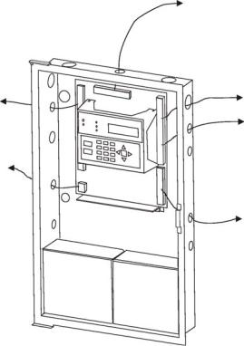
3.5Mounting the SK-5208
Read the environmental specifications in section 3.2 on page 1 before mounting the SK-5208 panel. The SK-5208 cabinet dimensions are:
16" W x 26.4" H x 4" D (40.64 cm W x 67.06 cm H x 10.16 cm D).
The SK-5208 panel should be located within a secured area, where it is accessible to main drop wiring runs and where it can be easily tested and serviced. End-users responsible for maintaining the panel should be able to hear alarms and troubles. When selecting a location, keep in mind that the panel itself is the main source of alarm and trouble annunciation.
When mounting on interior walls, use appropriate screw anchors in plaster. When mounting on concrete, especially when moisture can accumulate, the enclosure shall be placed or equipped so as to prevent moisture or water from entering and accumulating within the cabinet, and shall be mounted so there is a least 1/4” space between the enclosure and the concrete wall surface. A piece of plywood, standoffs, or other equivalent material can be used to space the cabinet from the concrete surface and then attach the SK-5208 to that spacing surface. Also mount any other desired components to the 1/4” spacing surface.
DO NOT flush-mount the SK-5208 cabinet in a wall designated as a fire break.
3.5.1Preventing Water Damage
Water damage to the fire system can be caused by moisture entering the cabinet through the conduits. Conduits that are installed to enter the top of the cabinet are most likely to cause water problems. Installers should take reasonable precautions to prevent water from entering the cabinet. Water damage is not covered under warranty.
3.6Current Draw Calculations
3.6.1Worksheet Requirements
The following steps must be taken when determining SK-5208 current draw and standby battery requirements.
Filling in the Current Draw Worksheet, Table 3-2 (Section 3.6.2)
1.For the SK-5208, the worst case current draw is listed for the panel and panel accessories. Fill in the number of devices that will be used in the system and compute the current draw requirements for alarm and standby. Record this information in Table 3-2 at Line A.
2.Add up the current draw for all smoke detectors and record in the table at Line B.
3.Add up all notification appliance loads and record in the table at Line C.
4.For notification appliances and auxiliary devices not mentioned in the manual, refer to the device manual for the current ratings.
5.Make sure that the total alarm current you calculated, including current for the panel itself, does not exceed 6.0 A. This is the maximum alarm current for the SK-5208 control panel.
If the current is above 6.0 A you will need to use a notification power expander(s) such as the 5495 to distribute the power loads so that the SK-5208 or the power expanders do not exceed their power rating. Refer to the current draw worksheets provided with the 5495 manuals so you do not exceed their power requirements.
6.Complete the remaining instructions in Table 3-2 for determining battery size requirements.
3-4
Model SK-5208 Installation Manual |
151204 |
3.6.2Current Draw Worksheet
Use Table 3-2 to determine current requirements during alarm/battery standby operation. (Copy the page if additional space is required.)
Table 3-2: Current Draw Calculations
|
Device |
|
# of Devices |
|
Current per Device |
Standby |
Alarm |
|||
|
|
|
Current |
Current |
||||||
|
|
|
|
|
|
|
|
|
||
|
|
|
|
|
|
|
|
|
|
|
|
|
|
|
|
|
|
|
|
|
|
|
For each device use this formula: |
This column X |
|
This column |
= Current per number of devices. |
|||||
|
SK-5208 Fire Panel (Current draw |
|
1 |
|
Standby: |
|
|
140 mA |
140 mA |
|
|
from battery) |
|
|
Alarm: |
|
**550 mA |
|
550 mA |
||
|
|
|
|
|
|
|||||
|
Panel Accessories |
|
|
|
|
|
|
|
|
|
|
SK-5217 Zone Expander |
|
(2 max.) |
|
Standby: |
|
|
60 mA |
mA |
|
|
|
|
Alarm: |
|
|
150 mA |
|
mA |
||
|
|
|
|
|
|
|
|
|||
|
5824 Serial/Parallel Interface |
|
(1 max.) |
|
Standby: |
|
|
45 mA |
mA |
|
|
Gateway Module |
|
|
Alarm: |
|
|
45 mA |
|
mA |
|
|
|
|
|
|
|
|
||||
|
5220 Direct Connect |
|
|
|
Standby: |
|
|
15 mA |
mA |
|
|
|
|
|
Alarm: |
|
|
15 mA |
|
mA |
|
|
|
|
|
|
|
|
|
|||
|
SK-5235 Annunciator |
|
(6 max.) |
|
Standby: |
|
|
30 mA |
mA |
|
|
|
|
Alarm: |
|
|
50 mA |
|
mA |
||
|
|
|
|
|
|
|
|
|||
|
|
|
|
|
Relay |
|
Standby: |
10 mA |
mA |
|
|
SK-5280 Status Display Module |
|
(8 max.) |
|
(max.) |
|
Alarm: |
80 mA |
|
mA |
|
|
|
Outputs |
|
Per output |
100 mA |
|
mA |
||
|
|
|
|
|
|
|
||||
A |
|
|
|
|
|
Max. |
700 mA |
|
mA |
|
|
|
|
|
|
|
|
||||
|
|
|
|
|
Total System Current |
|
|
|||
|
Smoke Detectors |
|
|
|
|
|
|
|
|
|
|
|
|
|
|
Standby: |
|
|
mA |
mA |
|
|
|
|
|
|
Alarm: |
|
|
mA |
|
mA |
|
|
|
|
|
Standby: |
|
|
mA |
mA |
|
|
|
|
|
|
Alarm: |
|
|
mA |
|
mA |
|
|
|
|
|
Standby: |
|
|
mA |
mA |
|
|
|
|
|
|
Alarm: |
|
|
mA |
|
mA |
|
|
|
|
|
Standby: |
|
|
mA |
mA |
|
B |
|
|
|
|
Alarm: |
|
|
mA |
|
mA |
|
|
|
|
Smoke Detector Current |
mA |
mA |
||||
|
Notification Appliances |
|
|
|
|
|
|
|
|
|
|
|
|
|
|
Alarm: |
|
|
mA |
|
mA |
|
|
|
|
|
Alarm: |
|
|
mA |
|
mA |
C |
|
|
|
|
Alarm: |
|
|
mA |
|
mA |
|
|
|
|
Notification Appliances Current |
|
mA |
||||
|
Additional Devices |
|
|
|
|
|
|
|
|
|
|
|
|
|
|
Standby: |
|
|
mA |
|
|
|
|
|
|
|
Alarm: |
|
|
mA |
|
|
|
|
|
|
|
Standby: |
|
|
mA |
|
|
D |
|
|
|
|
Alarm: |
|
|
mA |
|
|
|
|
|
|
Additional Devices Current |
|
mA |
||||
E |
Total current ratings of all devices in system (line A + line B + C +D) |
|
mA |
mA |
||||||
F |
|
|
|
|
|
|
||||
Total current ratings converted to amperes (line E x .001): |
|
|
|
A |
A |
|||||
G |
|
|
|
|
||||||
Number of standby hours (24 or 60 for NFPA 72, chapter 1, 1-5.2.5): |
|
H |
|
|||||||
H |
Multiply lines F and G. |
|
|
|
|
|
Total standby AH |
AH |
|
|
I |
Alarm sounding period in hours. (For example, 5 minutes = .0833 hours) |
|
|
H |
||||||
J |
Multiply lines F and I. |
|
|
|
|
|
Total alarm AH |
|
AH |
|
K |
*Add lines H and J. |
|
|
|
|
|
Total ampere |
AH |
|
|
|
|
|
|
|
|
hours required |
|
|
||
|
|
|
|
|
|
|
|
|
||
*Use next size battery with capacity greater than required.
**The SK-5208 and SK-5217 limits alarm current to 95mA per zone. The SK-5208 alarm current includes
3-5
Control Panel Installation |
151204 |
10% of zones in alarm, but in no case less then three zones per UL864
3.6.3Maximum Battery Standby Load
Table 3-3 shows the maximum battery standby load for the SK-5208 based on 24 and 60 hours of standby. The standby load calculations of line D in the Current Draw Calculation Worksheet (Table 3-2) must be less than the number shown in Table 3-3 for the battery size used and standby hours required.
Batteries larger then 18 AH will not fit into the SK-5208 cabinet and must be housed in the RBB remote battery box cabinet. See Section 3.8 for battery installation.
Table 3-3: Maximum Battery Standby Load
Rechargeable Battery Size |
Max. Load for 24 hrs. |
*Max. Load for 60 hrs. |
|
Standby, 5 mins. Alarm |
Standby, 5 mins. Alarm |
||
|
|||
|
|
|
|
|
|
|
|
7 AH |
270 mA |
105 mA |
|
|
|
|
|
12 AH |
475 mA |
190 mA |
|
|
|
|
|
18 AH |
685 mA |
270 mA |
|
|
|
|
|
35 AH |
1.1 A |
450 mA |
|
|
|
|
*Required for NFPA 72 Auxiliary Protected Fire Alarm systems for Fire Alarm Service (City Box) and Remote Station Protected Fire Alarm systems (Polarity Reversal) and Digital Alarm Communicator/Transmitter (DACT).
Warning!
Silent Knight does not support the use of batteries smaller than those listed in Table 3-3. If you use a battery too small for the installation, the system could overload the battery resulting in the installation having less than the required 24 hours standby power. Use Table 3-2 to calculate the correct battery amperes/hour rating needed for your installation.
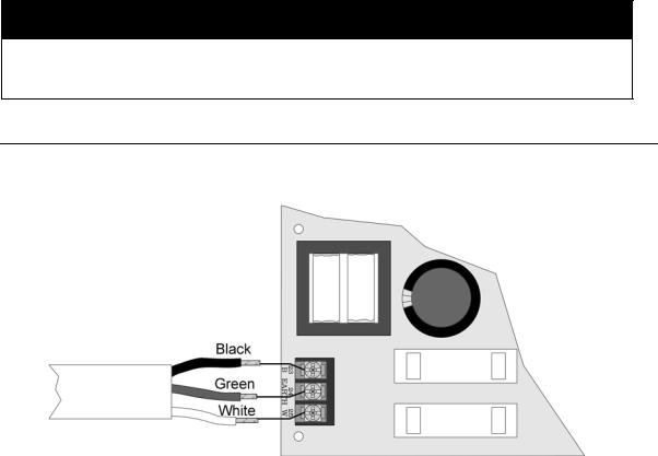
3.7AC Wiring
The Model SK-5208 power supply delivers 24 VDC at 6A for smoke detector power, notification device power, and accessory power. Figure 3-3 shows the AC connections to the SK-5208 control panel.
Figure 3-3 AC Wiring
3-6
Model SK-5208 Installation Manual |
151204 |
Warning
To reduce the risk of electrical shock, make sure that all power has been turned off or disconnected before attempting to connect the Model SK-5208 control panel. Do NOT apply power to this panel until all accessories are properly connected.
Note: Note: All conduit and wiring connected to the SK-5208 must meet the applicable National Electric Code, NFPA Standards, state, and local building code requirements. In all cases, the authority having jurisdiction takes precedence.
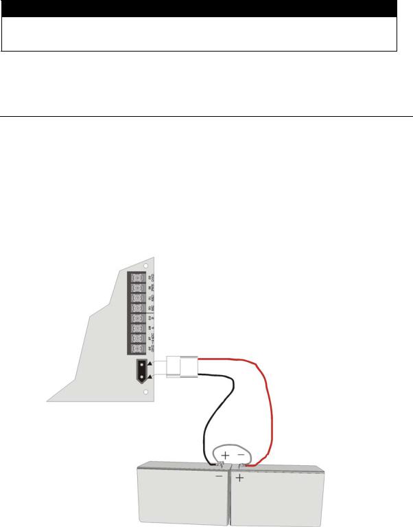
3.8Backup Batteries
The control panel battery charge capacity is 7.0 to 35.0 AH. Use 12V batteries of the same AH rating. Determine the correct AH rating as per your current load calculation (see 3.6.2).
Wire batteries in series to produce a 24-volt equivalent. Do not parallel batteries to increase the AH rating.
Batteries larger than 18 AH (not to exceed 35 AH) use the RBB Remote Battery Box. It is recommended that you replace the batteries every five years. The following steps and diagram explain how to connect the batteries.
1.Connect the black wire to the negative (-) side of battery #1.
2.Connect the jumper wire provided (P/N 140694) from the positive (+) side of battery #1 to the negative side of battery #2.
3.Connect the red wire to the positive (+) side of battery #2
|
|
|
RED |
Control Panel |
|
Black |
|
|
|
|
|
|
|
Battery Jumper |
|
Note: Replace batteries |
|
(P/N 140694) |
|
every 5 years. |
|
Shipped With Panel |
|
|
|
|
|
|
|
Battery #1 |
Battery #2 |
|
UL Listed 12VDC |
UL Listed 12VDC |
|
|
|
Battery Gell Cell |
Battery Gell Cell |
3-7

Control Panel Installation |
151204 |
Caution
Apply AC power before connecting the batteries to the power supply to prevent arcing on battery terminals.
Note: The total current draw on smoke power, accessory power, and notification device outputs must not exceed 6A.
3.9Terminal Strip Description
The terminal strips on the PC board are non-removable. Table 3-4 lists the functions of each terminal. See Section 3.4 for the board layout.
Table 3-4: Terminal Descriptions
Function |
Terminal |
Terminal Label |
Comments |
||
Number |
|||||
|
|
|
|
||
|
|
|
|
|
|
|
|
|
|
|
|
|
1 |
A |
|
Zone 1 input Class A (Style D) or Class B (Style B). See |
|
|
|
|
|
Section 3.11 for wiring configurations. |
|
Zone 1 input. |
2 |
B |
Z1 |
||
|
|||||
|
|
|
|||
3 |
C |
|
|||
|
|
|
|||
|
|
|
|
|
|
|
4 |
D |
|
|
|
|
|
|
|
|
|
|
5 |
A |
|
Zone 2 input Class A (Style D) or Class B (Style B). See |
|
|
|
|
|
Section 3.11 for wiring configurations. |
|
Zone 2 input |
6 |
B |
Z2 |
||
|
|||||
|
|
|
|||
7 |
C |
|
|||
|
|
|
|||
|
|
|
|
|
|
|
8 |
D |
|
|
|
|
|
|
|
|
|
Ground |
9 |
GND |
|
|
|
|
|
|
|
|
|
Zone 3 input |
10 |
Z3 |
|
Zone input Class B (Style B). Refer to Section 3.11.2. |
|
|
|
|
|
Power Limited at 100mA. Voltage 27.4 VDC. |
|
Power (Zone 3 & 4) |
11 |
PWR |
|
||
|
|
||||
|
|
|
|
|
|
Zone 4 input |
12 |
Z4 |
|
|
|
|
|
|
|
|
|
Zone 5 input |
13 |
Z5 |
|
|
|
|
|
|
|
|
|
Smoke Power |
14 |
PWR |
|
|
|
|
|
|
|
|
|
Zone 6 input |
15 |
Z6 |
|
|
|
|
|
|
|
|
|
Zone 7 input |
16 |
Z7 |
|
|
|
|
|
|
|
|
|
Smoke Power |
17 |
PWR |
|
|
|
|
|
|
|
|
|
Zone 8 input |
18 |
Z8 |
|
|
|
|
|
|
|
|
|
Zone9 input |
19 |
Z9 |
|
|
|
|
|
|
|
|
|
Smoke Power |
20 |
PWR |
|
|
|
|
|
|
|
|
|
Zone 10 input |
21 |
Z10 |
|
|
|
|
|
|
|
|
|
Ground |
22 |
GND |
|
|
|
|
|
|
|
|
|
|
23 |
B |
|
|
|
AC Power Connections |
|
|
|
|
|
24 |
Earth |
|
|
||
|
|
|
|
|
|
|
25 |
W |
|
|
|
|
|
|
|
|
|
|
26 |
GND |
|
Used to connect SK-5217 Zone Expanders and 5280 |
|
|
|
|
|
Status Display Modules to the control panel. Accessory |
|
|
27 |
+24DC |
|
||
SBUS Connections |
|
Power (terminals 26 and 27) provides 1 Amp total |
|||
|
|
|
|||
28 |
A |
|
|||
|
|
current. |
|||
|
|
|
|
||
|
29 |
B |
|
|
|
|
|
|
|
|
|
3-8
Model SK-5208 Installation Manual |
151204 |
Table 3-4: Terminal Descriptions
Function |
Terminal |
Terminal Label |
Comments |
||
Number |
|||||
|
|
|
|
||
|
|
|
|
|
|
|
|
|
|
|
|
|
30 |
SKI |
|
Used to connect 5235 remote annunciators to the control |
|
|
|
|
|
panel. |
|
Remote Annunciator |
31 |
SKO |
|
||
|
|
||||
Connections |
|
|
|
|
|
32 |
PWR |
|
|
||
|
|
|
|
|
|
|
33 |
GND |
|
|
|
|
|
|
|
|
|
Notification Appliance |
34 |
+ |
NAC4 |
3 Amp maximum per circuit. Voltage 27.4 VDC, 1.5 |
|
Circuit 4 |
|
|
Ohms Maximum. |
||
35 |
_ |
||||
|
|||||
|
|
|
|
Note: Total control panel current is 6 Amps. |
|
Notification Appliance |
36 |
+ |
NAC3 |
||
|
|||||
Circuit 3 |
|
|
|
||
37 |
_ |
|
|||
|
|
||||
|
|
|
|
|
|
Notification Appliance |
38 |
+ |
NAC2 |
|
|
Circuit 2 |
|
|
|
||
39 |
_ |
|
|||
|
|
||||
|
|
|
|
|
|
Notification Appliance |
40 |
+ |
NAC1 |
|
|
Circuit 1 |
|
|
|
||
41 |
_ |
|
|||
|
|
||||
|
|
|
|
|
|
|
42 |
NO |
|
Relay contacts are rated at 2.5 A, 24 VDC/24VAC |
|
|
|
|
|
(inductive rating). 5A, 24 VDC/24 VAC (resistive). |
|
Auxiliary Relay 4 |
43 |
COM |
|
||
|
Connect to power limited source only. |
||||
|
|
|
|
||
|
44 |
NC |
|
||
|
|
|
|||
|
|
|
|
|
|
|
45 |
NO |
|
|
|
Auxiliary Relay 3 |
|
|
|
|
|
46 |
COM |
|
|
||
|
|
|
|
|
|
|
47 |
NC |
|
|
|
|
|
|
|
|
|
|
48 |
NO |
|
|
|
Auxiliary Relay 2 |
|
|
|
|
|
49 |
COM |
|
|
||
|
|
|
|
|
|
|
50 |
NC |
|
|
|
|
|
|
|
|
|
|
51 |
NO |
|
|
|
Auxiliary Relay 1 |
|
|
|
|
|
52 |
COM |
|
|
||
|
|
|
|
|
|
|
53 |
NC |
|
|
|
|
|
|
|
|
|
|
54 |
TIP |
P2 |
Telephone line 2 connection terminals (see Section 3.10 |
|
|
|
|
for wiring diagram). |
||
Telco Line 2 |
55 |
RING |
|||
|
|||||
|
|
||||
|
|
|
|
||
56 |
TIP |
T2 |
|
||
|
|
||||
|
|
|
|
||
|
57 |
RING |
|
||
|
|
|
|||
|
|
|
|
|
|
|
58 |
TIP |
P1 |
Telephone line 1 connection terminals (see Section 3.10 |
|
|
|
|
for wiring diagram). |
||
Telco Line 1 |
59 |
RING |
|||
|
|||||
|
|
||||
|
|
|
|
||
60 |
TIP |
T1 |
|
||
|
|
||||
|
|
|
|
||
|
61 |
RING |
|
||
|
|
|
|||
|
|
|
|
|
|
3-9
Control Panel Installation |
151204 |
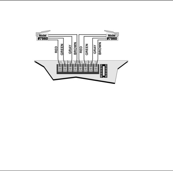
3.10Telephone Line Connection
The SK-5208 connects to two separate telephone lines to report data to the central station. An RJ31X jack should be installed by the telephone company for each line. Figure 3-4 shows how to wire the telephone line interconnect cords (not provided) to the SK-5208.
Note: To reduce the possibility of false alarms and transient damage, DO NOT bundle telephone wires together with initiation or notification device wires.
Supervised
Figure 3-4 Telephone Line Connection
The letter designator on the phone input indicates whether it is the Telco or House side of the phone circuit. For example terminals 60 and 61 are labeled T1, T = Telco side of the phone circuit and terminals 58 and 59 are labeled P1, P = Premise (House) side of the phone circuit.
The SK-5208 has built-in dual phone line monitors. These circuits will detect any fault in the phone lines by monitoring the DC voltage present on the lines. If phone line voltage drops below 3 VDC and is not corrected within approximately 60 seconds, an audible trouble signal will sound and the panel will report a line fault trouble over the remaining phone line.
A situation could occur where both phone lines appear to be good, but the dialer cannot get through to the central station on the first line. In this case, the SK-5208 will switch phone lines and attempt the call again using the second line. Make sure the phone lines are programmed properly (see Section 4).
Note: To comply with industry standards, this product is equipped with line seizure. Any time the system’s dialer needs to communicate with the central station, it will not be possible to use any telephones that are on the same line(s) as the system. Normally, this condition will last approximately one minute, but under adverse telephone circuit conditions, could last for as long as 15 minutes.
3.11 Detector Installation
3.11.1Class A (Style D) Zones
Zones 1 and 2 may be selected through programming as Class A (Style D) zones (see Section 4.2.2 for zone style programming). See Section 3.11.2 for Class B (Style B) configuration.
Each class A zone is a four-wire circuit that allows an alarm to be detected even after a single open or ground fault occurs. When a single open or ground fault occurs, the audible trouble signal will sound and the SK-5208 will report the trouble to the central station or remote station (if programmed to report troubles). If reporting to a remote station troubles may be transmitted to a secondary location.
Figure 3-5 shows how to wire a Class A (Style D) circuit. No end-of-line (EOL) resistors are needed for these
3-10
Model SK-5208 Installation Manual |
151204 |
zones. These zones must be wired using normally open contacts.
Supervised
Power Limited
Figure 3-5 Class A (Style D) Supervised Fire Circuit
Maximum voltage: |
17.5 to 28 VDC Full Wave Rectified |
Circuit Current: |
95 mA |
Maximum circuit Resistance: |
50 ohms |
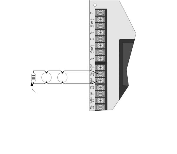
3.11.2Class B (Style B) Zones
Zones 3 through 10 are Class B (Style B) only fire zones. Zones 1 & 2 may also be programmed as Class A (Style D) or Class B (Style B), see Section 4.2.2 for zone 1 & 2 zone programming.
Each Class B zone consists of a two-wire circuit that will detect the occurrence of an open in the circuit, but may not be able to detect an alarm after such an occurrence. The detection of an open will cause the audible trouble signal to sound and the SK-5208 will report the trouble to the central or remote station (if programmed to do so).
Figure 3-6 shows how to wire a Class B (Style B) circuit. One side of each Class B circuit connects to a zone input terminal and the other side of each circuit connects to Smoke power. For each circuit, use a 4.7K-ohm EOL resistor wired in parallel with the normally open contact farthest from the panel.
Note: Zones 1 and 2 can be configured as either Class A or Class B. See also Section 3.11.1.
4.7 k EOL
UL Listed Model 7628
Supervised
Power Limited
Figure 3-6 Model SK-5208 Class B (Style B) Circuits
3-11
Control Panel Installation |
151204 |
Maximum circuit Resistance - 50 ohms
Maximum Total alarm current for all Class B (Style B) zones - 1 A
Maximum Standby Current per Zone:3.0 mA
Maximum Alarm Current per Zone:95 mA
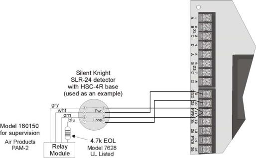
3.11.3Four-Wire Smoke Detector Connection
Figure 3-7 illustrates how UL listed four-wire smoke detectors must be connected to Class B (Style B) zones.
When wiring a four-wire smoke detector to the Class B (Style B) zones, you must use a Power Supervision Unit, such as Silent Knight’s 160150.
Note: Mount the PAM-2 and the end-of-line resistor at the last device on the circuit.
Supervised
Power Limited
Figure 3-7 Four-Wire Smoke Detector Wiring
See Appendix A for a list of four-wire smoke detectors that may be used with the SK-5208.
3-12
Model SK-5208 Installation Manual |
151204 |
3.11.4Two-Wire Smoke Detector Connection
Figure 3-8 shows how to connect two-wire smoke detectors to Class B (Style B) zones.
Silent Knight SLK-24F 2-wire detector
with HSB-224 base
––
+ |
+ |
|
Supervised |
4.7 k |
Power Limited |
UL Listed EOL |
|
Model 7628 |
|
Figure 3-8 Two-Wire Smoke Detector Wiring
See Appendix A for a list of two-wire smoke detectors that may be used with the SK-5208.
Note: Two-wire detectors can be configured for Enhanced Mode. Enhanced mode is smoke verification for zones with 2-wire detectors and contact type devices, such as pull stations, used on the same circuit. If the alarm current is greater than 78 mA, the smoke verification cycle will not occur. See Section 4.2.1 Verify Options under the Zone Options Menu to program initiation circuits for enhanced mode.
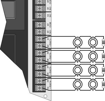
3.12Supervised Notification Appliance Outputs
Note: To reduce the possibility of false alarms and transient damage, DO NOT bundle telephone wires together with notification circuit wires.
The SK-5208 provides four Class B (Style Y) supervised notification circuit outputs to annunciate alarm conditions. For proper operation, you must use polarized sounding devices with a 4.7k ohm end-of-line resistor
3-13
Control Panel Installation |
151204 |
on each circuit. Figure 3-9 shows how to connect the notification circuits to the SK-5208.
3 Amps Max. per circuit full wave rectified, 27.5 VDC, 1.5 Ohms Maximum.
Supervised
Power Limited
4.7 k
UL Listed EOL Model 7628
Figure 3-9 Supervised Notification Appliance Wiring
3 Amp maximum current draw from any single NAC output (not to exceed a total current draw of 6 amps for the control panel). See Appendix A for a list of the UL notification appliances that can be used with the SK-5208. Contact Silent Knight if you have any questions about compatible notification circuits.
All circuit are regulated unless used for releasing service in which case they are considered special applications. See Section 5.5 for details on releasing.
3-14
Model SK-5208 Installation Manual |
151204 |
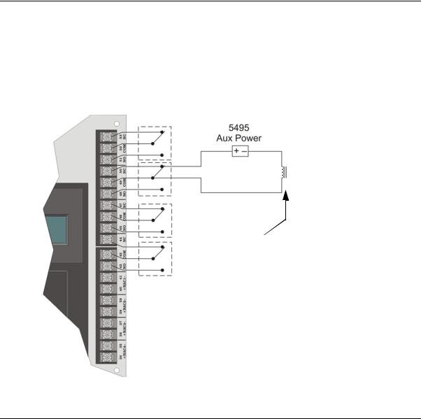
3.13 Auxiliary Relays
The SK-5208 provides four programmable auxiliary relay outputs. Relays can be programmed to activate for the following conditions, either for all zones or by individual zone: pre-alarm (not acceptable for NFPA 72 Central Station), fire alarm, auxiliary alarm, alarm by zone, and system or circuit troubles (loss of AC, low battery, failed to communicate, phone line troubles, fire drills, and notification circuit troubles).
Refer to the SK-5208 programming manual for more information. Figure 3-10 shows the relay contact connections using a door holder application as an example.
Note: Relays programmed as “Trouble” will be active during normal state and deactivated during a trouble condition.
Door Holder
ESL DHX 1224
Relay contacts are rated at
2.5 A, 24 VDC/24VAC (inductive rating). 5A, 24 VDC/24 VAC (resistive).
Figure 3-10 Auxiliary Relays
3.14 Accessory Devices
The section describes how to install the SK-5235 Remote Annunciator, SK-5217 Zone Expander, the 5824 Serial/Parallel Printer Module, and the SK-5280 Status Display Module. All circuits are 24 VDC regulated. All S-Bus devices are Style 1 Class B as per NFPA 72.
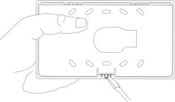
3.14.1Setting ID Codes
Before installing the SK-5235, SK-5217, 5824 or SK-5280, you must first set their identification codes. Each device must be given its own identification code. For example: each SK-5235 needs a unique ID code, but a SK5235 can have the same ID code as a
SK-5217. Each type of device has it’s own device type programmed into it enabling the control panel to distinguish between the different devices.
On the back of each device is a small 4-position dip switch used to set the ID code. Use the chart below to
3-15
Control Panel Installation |
151204 |
determine the dip switch positions for each possible ID code.
Table 3-5: ID Dip Switch Settings
|
ID Number |
|
Switches1 |
|
|
|
|
1 |
2 |
3 |
4 |
|
|
|
|
|
|
0 2 |
|
Down |
Down |
Down |
Down |
1 |
|
Up |
Down |
Down |
Down |
|
|
|
|
|
|
2 |
|
Down |
Up |
Down |
Down |
|
|
|
|
|
|
3 |
|
Up |
Up |
Down |
Down |
|
|
|
|
|
|
4 |
|
Down |
Down |
Up |
Down |
|
|
|
|
|
|
5 |
|
Up |
Down |
Up |
Down |
|
|
|
|
|
|
6 |
|
Down |
Up |
Up |
Down |
|
|
|
|
|
|
7 |
|
Not used3 |
|
|
|
|
|
|
|
|
|
8 |
|
|
|
|
|
|
|
|
|
|
|
|
|
|
|
|
|
1. Switch Settings: Up = On |
Down = Off |
|
|||
2.Not supervised.
3.ID number 7 and 8 are not valid ID settings.
3.14.2Model SK-5235 Remote Annunciator
The SK-5235 performs all system operation. It also provides trouble and alarm information and can be used for programming. The control panel can support up to six SK-5235 Remote Annunciators.
Upon initial power up, the address of each SK-5235 is displayed on the LCD. (Annunciators with address 0 will not be supervised.)
3.14.2.1 Mounting the SK-5235 Remote Annunciator
The SK-5235 Remote Annunciators must be mounted on a dual gang electrical box. To mount the annunciator:
1.Remove the rear mounting plate by inserting a #4 flat blade screwdriver into the slots on the bottom edge of the annunciator. See Figure 3-11. Gently turn the screwdriver until the mounting plate pulls away from the frame.
Figure 3-11 Rear Mounting Plate Removal
3-16
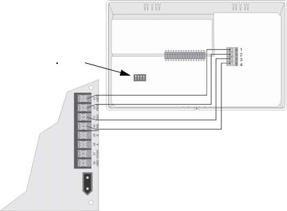
Model SK-5208 Installation Manual |
151204 |
2.Secure it to the wall using #6 or #8 screws. The mounting plate should be oriented so that the word TOP is toward the top of the plate and facing you. A square hole is provided in the mounting plate to run the wiring to the annunciator.
3.When all of the wires have been connected to the annunciator, set the top of the annunciator over the tabs on the top of the mounting plate. Make sure the wires do not get pinched between the frame and the mounting plate. Press each corner of the bottom side onto the annunciator mounting plate until you hear it click. You may have to gently squeeze the annunciator (top to bottom) to align it while snapping the bottom edge into place.
3.14.2.2 Wiring the SK-5235
Follow these steps to properly wire the SK-5235 to the control panel.
1.Remove power from the control panel.
2.Wire the SK-5235s as shown in Figure 3-12.
3.Set the ID number. See Table 3-5.
Note: The ID number of 7 is reserved for the built-in touchpad on the SK-5208.
4.Reapply power the control panel.
When the annunciator powers up, it will display its ID code and current status of the panel.
ID DIP switches 
Supervised
Power Limited
Class B
Figure 3-12 Model SK-5235 Connection
Note: Each 5235 touchpad can be individually supervised. See Section 4.2.2 for programming touchpads as supervised.
3-17
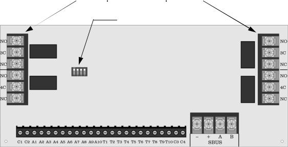
Control Panel Installation |
151204 |
3.14.3Model SK-5280 Status Display Module
The Model SK-5280 Status Display module provides outputs and control functions for remote annunciation of alarm, trouble, and supervisories for each zone.The system can supervise up to eight SK-5280 Status Display Modules.
Note: The driver outputs are non-supervised. Relays must be connected to power limited sources only.
 4 On-board Relays
ID Number
DIP Switch
Relay Rating
2.5A @ 30 VDC/120 VAC
|
|
|
|
|
|
|
|
|
|
|
Alarm |
|
Outputs |
Trouble |
|
Outputs |
|
SBUS |
|
Connector |
|
|
|
|||||||||
|
|
|
|
|||||||
1/4” spacing must be maintained between power limited & non-power limited wiring
Figure 3-13 Model 5280 Board Layout
The SK-5280 has 1 connector which has 10 outputs for alarms and 10 outputs for trouble annunciation. These outputs are active low. Each output can provide up to 100 mA of current, with a total limitation of 700 mA.
The module has 4 normally open non-dedicated relays that can be wired to be active with any of the outputs.
Wire the SK-5280 as shown in Figure 3-14. Maintain a physical separation of one-half inch or more between field wires and connection points to prevent damage from transients.
Note: SILENCE does not affect SK-5280 outputs. To reset a SK-5280 output, the alarm or trouble condition must be restored.
The SK-5280 can be used to interface to LED annunciator.
The SK-5280 can be programmed to indicate alarms and trouble status for; zones 1 - 10, zones 11 - 20, zones 21
3-18
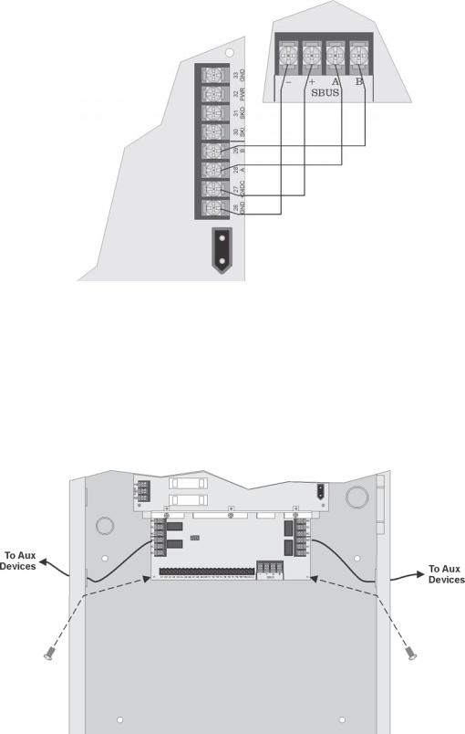
Model SK-5208 Installation Manual |
151204 |
- 30, or system status outputs. See Section 4.2.11.
5280
Supervised
Power Limited
Control Class B
Panel
Figure 3-14 Model SK-5280 Connection to the Control Panel
3.14.3.1 Mounting the SK-5280
The SK-5280 into a metal bracket and standoffs in the SK-5208 cabinet or into SK-2190 accessory cabinet.
Mounting the SK-5280 into SK-5208 Cabinet
Follow these steps to properly mount the SK-5280 into the SK-5208 cabinet:
1.Remove power from the control panel.
2.Mount the SK-5280 onto the standoffs and bracket located in the cabinet. See Figure 3-15.
Figure 3-15 Installing the 5280 Into the 5208 Cabinet
3-19
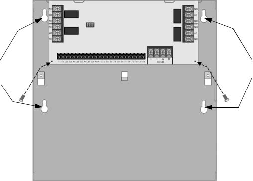
Control Panel Installation |
151204 |
3.Connect the SK-5280 to the SK-5208 control panel as shown in Figure 3-14.
4.Set the ID number (see Figure 3-13 for ID DIP switch location). See also Section 3.14.1for information on setting ID numbers.
5.Reconnect power to the control panel.
Mounting the SK-5280 into the SK-2190 Accessory Cabinet.
Follow these steps to properly mount the SK-5280 into the SK-2190 cabinet:
1.Mount the remote cabinet using the cabinet mounting holes. See Figure 3-16. Refer to Section 3.5 for proper cabinet mounting procedures.
2.Remove power from the control panel.
3.Mount the SK-5280 onto the standoffs and bracket located in the cabinet. See Figure 3-16.
Mounting
Mounting Holes
Holes
Figure 3-16 Model SK-5280 Remote Installation
4.Connect the SK-5280 to the SK-5208 control panel as shown in Figure 3-14.
5.Set the ID number (see Figure 3-13 for ID DIP switch location). See also Section 3.14.1for information on setting ID numbers.
6.Reconnect power to the control panel.
3.14.3.2 Wiring Relays
The four on-board relays can be triggered by the active low outputs. For example, the alarm outputs can all be wired to relay 3 and the trouble outputs can be wired to relay 4
(see Figure 3-17).
3-20
Loading...