


EVS
Table of contents
 Loading...
EVS-Series
Emergency Voice System
Installation and
Operations Manual
Document LS10062-001SK-E
02/12/13 Rev:
P/N LS100062-001SK-E ECN: 13-0146
A


Installation Procedure
Installation Precautions - Adherence to the following will aid in problem-free
installation with long-term reliability: WARNING - Several different sources of power
can be connected to the fire alarm control panel. Disconnect all sources of power
before servicing. Control unit and associated equipment may be damaged by
removing and/or inserting cards, modules, or interconnecting cables while the unit is
energized. Do not attempt to install, service, or operate this unit until manuals are
read and understood. CAUTION - System Re-acceptance Test after Software
Changes: To ensure proper system operation, this product must be tested in
accordance with NFPA 72 after any programming operation or change in site-specific
software. Re-acceptance testing is required after any change, addition or deletion of
system components, or after any modification, repair or adjustment to system
hardware or wiring. All components, circuits, system operations, or software functions
known to be affected by a change must be 100% tested. In addition, to ensure that
other operations are not inadvertently affected, at least 10% of initiating devices that
are not directly affected by the change, up to a maximum of 50 devices, must also be
tested and proper system operation verified. This system meets NFPA requirements
for operation within the range of 0°C-49°C (32°F-120°F) or humidity within the range
of 10%-93% at 30°C (86°F) noncondensing. However, the useful life of the system's
standby batteries and the electronic components may be adversely affected by
extreme temperature ranges and humidity. Therefore, it is recommended that this
system and its peripherals be installed in an environment with a normal room
temperature of 15-27º C/60-80º F. Verify that wire sizes are adequate for all
initiating and indicating device loops. Most devices cannot tolerate more than a 10%
I.R. drop from the specified device voltage. Like all solid state electronic devices,
this system may operate erratically or can be damaged when subjected to lightning
induced transients. Although no system is completely immune from lightning
transients and interference, proper grounding will reduce susceptibility. Overhead or
outside aerial wiring is not recommended, due to an increased susceptibility to
nearby lightning strikes. Consult with the Technical Services Department if any
problems are anticipated or encountered. Remove DC power prior to removing or
inserting circuit boards. Failure to do so can damage circuits. Remove all electronic
assemblies prior to any drilling, filing, reaming, or punching of the enclosure. When
possible, make all cable entries from the sides or rear. Before making modifications,
verify that they will not interfere with battery, transformer, or printed circuit board
location. Do not tighten screw terminals more than 9 in-lbs. Over-tightening may
damage threads, resulting in reduced terminal contact pressure and difficulty with
screw terminal removal. Fire alarm control panels contain static-sensitive
components. Always ground yourself with a proper wrist strap before handling any
circuits so that static charges are removed from the body. Use static suppressive
packaging to protect electronic assemblies removed from the unit.
Follow the instructions in the installation, operating, and programming manuals.

These instructions must be followed to avoid damage to the control panel and
associated equipment. FACP (Fire Alarm Control Panel) operation and reliability
depend upon proper installation.
Equipment used in the system may not be technically compatible with the control. It
is essential to use only equipment listed for service with your control panel.
Telephone lines needed to transmit alarm signals from a premise to a central
monitoring station may be out of service or temporarily disabled. The most common
cause of fire alarm malfunctions, however, is inadequate maintenance. All devices
and system wiring should be tested and maintained by professional fire alarm
installers following written procedures supplied with each device. System inspection
and testing should be scheduled monthly or as required by national and/or local fire
codes. Adequate written records of all inspections should be kept.

Contents
Section 1
Overview ...................................................................................................................................................... 1-1
1.1 Optional Accessories ................................................................................................................1-1
1.2 Features ...................................................................................................................................1-2
1.3 About This Manual ...................................................................................................................1-2
1.3.1 Terms Used in this Manual ................................................................................................1-3
1.4 How to Contact Silent Knight ....................................................................................................1-4
Section 2
Agency Listings, Approvals, and Requirements ................................... 2-1
2.1 Federal Communications Commission (FCC) ..........................................................................2-1
2.2 Underwriters Laboratories (UL) ................................................................................................2-2
2.2.1 Requirements for All Installations ......................................................................................2-2
2.2.2 Requirements for Central Station Fire Alarm Systems ......................................................2-2
2.2.3 Requirements for Local Protected Fire Alarm Systems .....................................................2-2
2.2.4 Requirements for Remote Station Protected Fire Alarm Systems .....................................2-3
Section 3
Before you Begin Installation .......................................................................................... 3-1
3.1 Environmental Specifications ...................................................................................................3-1
3.2 Wiring Specifications ................................................................................................................3-1
3.3 SBUS Specifications ................................................................................................................3-3
3.4 Electrical Specifications ............................................................................................................3-3
Section 4
EVS Device Installation ............................................................................................................ 4-1
4.1 Mounting the Cabinet ...............................................................................................................4-1
4.1.1 Preventing Water Damage .................................................................................................4-1
4.1.2 Surface Mounting ...............................................................................................................4-1
4.1.3 Recessed Mounting ...........................................................................................................4-3
4.1.3.1 Cabinet Door and Dead Front Removal ...................................................................4-4
4.2 Connecting AC Power and Batteries ........................................................................................4-5
4.3 The EVS-VCM ..........................................................................................................................4-6
4.3.1 EVS-VCM Board Layout ....................................................................................................4-6
4.3.2 Connecting the EVS-VCM to the SBUS .............................................................................4-8
4.3.3 Installing the Microphone ...................................................................................................4-8
4.3.4 To Remove the EVS-VCM ...............................................................................................4-10
4.4 Installing the EVS-SW24 Switch Expander ............................................................................4-11
4.5 Installing the EVS-50W ..........................................................................................................4-13
4.5.1 EVS-50W Board Layout ...................................................................................................4-13
1

4.5.2 Mounting the EVS-50W ...................................................................................................4-14
4.5.3 Wiring Specifications ........................................................................................................4-15
4.5.4 Speaker Wiring ................................................................................................................4-16
4.5.4.1 Wiring Lengths .......................................................................................................4-17
4.5.4.2 Class B (Style Y) ....................................................................................................4-18
4.5.4.3 Class A (Style Z) ....................................................................................................4-18
4.5.5 VBUS Wiring ....................................................................................................................4-19
4.5.6 SBUS Wiring ....................................................................................................................4-20
4.5.7 Connecting AC Power ......................................................................................................4-21
4.5.8 Backup Battery for EVS-50W ...........................................................................................4-23
4.5.9 Calculating Current Draw and Standby Battery ...............................................................4-24
4.6 Installing the EVS-125W ........................................................................................................4-25
4.6.1 EVS-125W Board Layout .................................................................................................4-25
4.6.2 Mounting the EVS-125W .................................................................................................4-26
4.6.3 Wiring Specifications ........................................................................................................4-27
4.6.4 Speaker Wiring ................................................................................................................4-28
4.6.4.1 Wiring Lengths .......................................................................................................4-29
4.6.4.2 Class B (Style Y) ....................................................................................................4-30
4.6.4.3 Class A (Style Z) ....................................................................................................4-30
4.6.5 VBUS Wiring ....................................................................................................................4-31
4.6.6 SBUS Wiring ....................................................................................................................4-32
4.6.7 Connecting AC Power ......................................................................................................4-33
4.6.8 Backup Battery for EVS-125W .........................................................................................4-34
4.6.9 Calculating Current Draw and Standby Battery ...............................................................4-35
4.7 Installing the EVS-CE4 ...........................................................................................................4-36
4.8 Installing the EVS-RVM ..........................................................................................................4-38
4.8.1 EVS-RVM Board Layout ..................................................................................................4-38
4.8.2 Wiring the EVS-RVM .......................................................................................................4-40
4.8.3 Installing the Microphone .................................................................................................4-42
4.8.4 To Remove the EVS-RVM ...............................................................................................4-43
4.9 Addressing SBUS Devices .....................................................................................................4-45
Silent Knight Fire Product Warranty and Return Policy
Manufacturer Warranties and Limitation of Liability
2

Section 1 Overview
The Emergency Voice System Packages are a combination of the addressable fire
alarm control panel and voice integration control all in one package. The general idea
of the Emergency Voice System is to activate a message giving building occupants
instructions about an emergency event. This manual contains information on how to
install and operate the following Emergency Voice System Packages:
Model Number Consists of These Part Numbers
EVS-Series
5820XL-EVS
EVS-RCU
1.1 Optional Accessories
This manual also contains information on how to install the following compatible
accessory with the EVS series equipment:
5820XL FACP
EVS-VCM (Voice control Module)
EVS-RVM (Remote Voice Module)
5860 (Remote Annunciator)
Model Number Description
EVS-SW24
EVS-50W 50 watt amplifier with 4 separate audio circuits
EVS-125W 125 watt amplifier with 4 separate audio circuits
EVS-CE4 Provides four additional audio circuits for each EVS-50W
Adds 24 additional switches to the EVS-VCM or EVS-RVM to manually select various voice
output groups for emergency announcements from the on-board microphone
LS10062-001-SK-E 1-1

EVS Series Emergency Voice System Installation Manual
1.2 Features
EVS-Series
• The EVS-VCM has a built-in Digital Message Repeater.
• 15 recordable one minute messages that can be mapped to eight EVS.
• Single enclosure for system control components.
• SBUS addressable amplifier. The system can support a combination of up to four
EVS-50W 50 watt amplifier or EVS-125W 125 watt amplifiers for a maximum of
500 watts per system.
• On-board supervised microphone.
• 5820XL-EVS can support up to four EVS-RCU’s (Remote Command Units).
• Up to 32 mappable speaker circuits using a combination of EVS-50W or EVS125W’s and EVS-CE4’s.
• Supports 25 Vrms or 70.7 Vrms speaker circuits using EVS-50W.
1.3 About This Manual
This manual is intended to be a complete reference for all installation and operation
tasks. Please let us know if the manual does not meet your needs in any way. We
value your feedback!
1-2 LS10062-001-SK-E

1.3.1 Terms Used in this Manual
The following terminology is used with the this system:
Term Description
EVS
FACP Fire Alarm Control Panel
LOC
Mass Notification
EVS-Series
EVS Device
EVS Control
EVS Device Priority
EVS Super User
VBUS
Module
Main control panel Refers to 5820XL-EVS control panel in the EVS-Series cabinet.
Input Point
Input Zone A protected area made up of input points.
Output Point
(or Output Circuit)
Audio Circuits Are output groups that are defined as voice output groups.
Group (or “Output Group”)
Output (or “Cadence”)
Pattern
Mapping
Emergency Voice System.The features of the control panel and accessories that
provide Mass Notification functionality as described in UL standard 2572.
Local Operator's Console. The user interface for a Mass Notification System. In
the Silent Knight product line, this would be the interface provided by the 5820XLEVS or the EVS-RCU.
A way of protecting life by relaying specific event information to a building or site
including voice and/or audible and visual signals.
When this is used in a statement, it would indicate the that statement applies to
the 5820XL-EVS control panels.
A LOC or a 5880 module that is programmed as an EVS device. These are used
as inputs for triggering the EVS.
EVS Control is a mode that all EVS Devices need to be in to be able to change
the current state of the EVS. EVS Control is requested by using the EVS Control
Button on LOC stations and is automatically requested for EVS 5880 Device
contact triggers along with the EVS Aux Input triggers of the VCM and RVM.
The priority level which is programmed for ever EVS Device. In order from lowest
to highest; Normal, Medium, High.
A user profile provided option that allows the user to override all EVS Control
rules and gain EVS Control.
The VBUS is an analog voice bus that carries the recorded voice messages from
the EVS-VCM to the EVS-50W/125Ws, or the voice messages generated from a
system microphone to the EVS-50W/125W’s.
The term module is used for all hardware devices except for SLC addressable
devices and notification appliances.
An addressable sensing device, such as a smoke or heat detector or a contact
monitor device.
A notification point or circuit for notification appliances. Relay circuits and
auxiliary power circuits are also considered output points. The output group can
be specifically defined as an output group to be used for voice evacuation circuits.
A group of output points. Operating characteristics are common to all output
points in the group.
The pattern that the output will use, for example, Constant, March Code, ANSI
3.41. Applies to zones and special system events.
Mapping is the process of specifying which outputs are activated when certain
events occur in the system.
Overview
LS10062-001-SK-E 1-3

EVS Series Emergency Voice System Installation Manual
1.4 How to Contact Silent Knight
If you have a question or encounter a problem not covered in this manual, contact
Silent Knight Technical Support at 800-446-6444. www.silentknight.com
To order parts, contact Silent Knight Sales at 800-328-0103.
1-4 LS10062-001-SK-E

Overview
Limitations of Fire Alarm Systems
Manufacturer recommends that smoke and/or heat detectors be located throughout a
protected premise following the recommendations of the current edition of the
National Fire Protection Association Standard 72 (NFPA 72), manufacturer’s
recommendations, State and local codes, and the recommendations contained in
Guide for the Proper Use of System Smoke Detectors, which is made available at no
charge to all installing dealers. A study by the Federal Emergency Management
Agency (an agency of the United States government) indicated that smoke detectors
may not go off or give early warning in as many as 35% of all fires. While fire alarm
systems are designed to provide warning against fire, they do not guarantee warning
or protection against fire. A fire alarm system may not provide timely or adequate
warning, or simply may not function, for a variety of reasons. For example:
• Particles of combustion or smoke from a developing fire may not reach the
sensing chambers of smoke detectors because:
Barriers such as closed or partially closed doors, walls, or chimneys may inhibit
particle or smoke flow.
Smoke particles may become cold stratify, and not reach the ceiling or upper
walls where detectors are located.
Smoke particles may be blown away from detectors by air outlets.
Smoke particles may be drawn into air returns before reaching the detector.
In general, smoke detectors on one level of a structure cannot be expected to sense
fires developing on another level.
• The amount of smoke present may be insufficient to alarm smoke detectors.
Smoke detectors are designed to alarm at various levels of smoke density. If such
density levels are not created by a developing fire at the location of detectors, the
detectors will not go into alarm.
• Smoke detectors, even when working properly, have sensing limitations.
Detectors that have photoelectric sensing chambers tend to detect smoldering
fires better than flaming fires, which have little visible smoke. Detectors that have
ionizing-type sensing chambers tend to detect fast flaming fires better than
smoldering fires. Because fires develop in different ways and are often
unpredictable in their growth, neither type of detector is necessarily best and a
given type of detector may not provide adequate warning of a fire.
• Smoke detectors are subject to false alarms and nuisance alarms and may have
been disconnected by users. For example, a smoke detector located in or near a
kitchen may go into nuisance alarm during normal operation of kitchen
appliances. In addition, dusty or steamy environments may cause a smoke
detector to falsely alarm. If the location of a smoke detector causes an abundance
of false alarms or nuisance alarms, do not disconnect the smoke detector; call a
professional to analyze the situation and recommend a solution.
• Smoke detectors cannot be expected to provide adequate warning of fires caused
LS10062-001-SK-E 1-5

EVS Series Emergency Voice System Installation Manual
by arson, children playing with matches (especially within bedrooms), smoking in
bed, violent explosions (caused by escaping gas, improper storage of flammable
materials, etc.).
• Heat detectors do not sense particles of combustion and are designed to alarm
only when heat on their sensors increases at a predetermined rate or reaches a
predetermined level. Heat detectors are designed to protect property, not life.
• Warning devices (including horns, sirens, and bells) may not alert people or wake
up sleepers who are located on the other side of closed or partially open doors. A
warning device that activates on a different floor or level of a dwelling or structure
is less likely to awaken or alert people. Even persons who are awake may not
notice the warning if the alarm is muffled by noise from a stereo, radio, air
conditioner or other appliance, or by passing traffic. Audible warning devices may
not alert the hearing-impaired (strobes or other devices should be provided to
warn these people). Any warning device may fail to alert people with a disability,
deep sleepers, people who have recently used alcohol or drugs, or people on
medication or sleeping pills.
Please note that:
i) Strobes can, under certain circumstances, cause seizures in people with con-
ditions such as epilepsy.
ii) Studies have shown that certain people, even when they hear a fire alarm sig-
nal, do not respond or comprehend the meaning of the signal. It is the property
owner’s responsibility to conduct fire drills and other training exercises to make
people aware of fire alarm signals and instruct on the proper reaction to alarm
signals.
iii) In rare instances, the sounding of a warning device can cause temporary or
permanent hearing loss.
• Telephone lines needed to transmit alarm signals from a premises to a central
station may be out of service or temporarily out of service. For added protection
against telephone line failure, backup radio transmission systems are
recommended.
• System components, though designed to last many years, can fail at any time. As
a precautionary measure, it is recommended that smoke detectors be checked,
maintained, and replaced per manufacturer’s recommendations.
• System components will not work without electrical power. If system batteries are
not serviced or replaced regularly, they may not provide battery backup when AC
power fails.
• Environments with high air velocity or that are dusty or dirty require more frequent
maintenance.
In general, fire alarm systems and devices will not work without power and will not
function properly unless they are maintained and tested regularly.
While installing a fire alarm system may make the owner eligible for a lower insurance
rate, an alarm system is not a substitute for insurance.
1-6 LS10062-001-SK-E
Property owners should

Overview
continue to act prudently in protecting the premises and the people in their premises
and should properly insure life and property and buy sufficient amounts of liability
insurance to meet their needs.
Requirements and recommendations for proper use of fire alarm systems including smoke detectors and other fire alarm devices:
Early fire detection is best achieved by the installation and maintenance of fire
detection equipment in all rooms and areas of the house or building in accordance
with the requirements and recommendations of the current edition of the National Fire
Protection Association Standard 72, National Fire Alarm Code (NFPA 72), the
manufacturer’s recommendations, State and local codes and the recommendations
contained in Guide for the Proper Use of System Smoke Detectors, which is made
available at no charge to all installing dealers. For specific requirements, check with
the local Authority Having Jurisdiction (ex. Fire Chief) for fire protection systems.
Requirements and Recommendations include:
• Smoke Detectors shall be installed in sleeping rooms in new construction and it is
recommended that they shall also be installed in sleeping rooms in existing
construction.
• It is recommended that more than one smoke detector shall be installed in a
hallway if it is more than 30 feet long.
• It is recommended that there shall never be less then two smoke detectors per
apartment or residence.
• It is recommended that smoke detectors be located in any room where an alarm
control is located, or in any room where alarm control connections to an AC
source or phone lines are made. If detectors are not so located, a fire within the
room could prevent the control from reporting a fire.
• All fire alarm systems require notification devices, including sirens, bells, horns,
and/or strobes. In residential applications, each automatic alarm initiating device
when activated shall cause the operation of an alarm notification device that shall
be clearly audible in all bedrooms over ambient or background noise levels (at
least 15dB above noise) with all intervening doors closed.
• It is recommended that a smoke detector with an integral sounder (smoke alarm)
be located in every bedroom and an additional notification device be located on
each level of a residence.
• To keep your fire alarm system in excellent working order, ongoing maintenance is
required per the manufacturer’s recommendations and UL and NFPA standards.
At a minimum the requirements of Chapter 7 of NFPA 72 shall be followed. A
maintenance agreement should be arranged through the local manufacturer’s
representative. Maintenance should be performed annually by authorized
personnel only.
The most common cause of an alarm system not functioning when a fire occurs is
inadequate maintenance. As such, the alarm system should be tested weekly to
LS10062-001-SK-E 1-7

EVS Series Emergency Voice System Installation Manual
make sure all sensors and transmitters are working properly.
SURVIVABILITY:
Per the National Fire Alarm Code, NFPA 72, all circuits necessary for the operation of
the notification appliances shall be protected until they enter the evacuation signaling
zone that they serve. Any of the following methods shall be considered acceptable as
meeting these requirements:
1) A 2-hour rated cable or cable system
2) A 2-hour rated enclosure
3) Performance alternatives approved by Authority Having Jurisdiction
1-8 LS10062-001-SK-E

Section 2 Agency Listings, Approvals, and Requirements
2.1 Federal Communications Commission (FCC)
1. The following information must be provided to the telephone company before the
FACP can be connected to the phone lines:
A Manufacturer: Silent Knight by Honeywell
B Model Number: 5820XL-EVS
C FCC registration number: AC6 USA-34758-AL-E
Ringer equivalence: 0.8B
D Type of jack: RJ31X
E Facility Interface Codes: Loop Start: 02LS2
F Service Order Code: 9.0F
2. This device may not be directly connected to coin telephone or party line services.
3. This device cannot be adjusted or repaired in the field. In case of trouble with the
device, notify the installing company or return to:
Silent Knight by Honeywell
12 Clintonville Road
Northford, CT 06472-1610
203-484-7161 or 800-328-0103
www.silentknight.com
4. If the FACP causes harm to the telephone network, the telephone company will
notify the user in advance that temporary discontinuance of service may be
required. If advance notice is not practical, the telephone company will notify the
user as soon as possible. Users have the right to file complaints, if necessary, with
the Federal Communications Commission.
5. The telephone company may make changes in its facilities, equipment, operations, or procedures that could affect the operation of the equipment. If this happens, the telephone company will provide advance notice to allow you to make
the necessary modifications to maintain uninterrupted service.
Warning
This device has been verified to comply with FCC Rules Part 15. Operation is subject to the following
conditions: (1) This device may not cause radio interference, and (2) This device must accept any
interference received, including interference that may cause undesired operation.
LS10062-001-SK-E 2-1

EVS Series Emergency Voice System Installation Manual
2.2 Underwriters Laboratories (UL)
2.2.1 Requirements for All Installations
General requirements are described in this section. When installing an individual
device, refer to the specific section of the manual for additional requirements. The
following subsections list specific requirements for each type of installation (for
example, Central Station Fire Alarm systems, Local Protected Fire Alarm systems,
and so on).
1. All field wiring must be installed in accordance with NFPA 70 National Electric
Code.
2. Use the addressable smoke detectors specified in FACP installation manual.
3. Use UL listed notification appliances compatible with the FACP from those specified in the Appendix at the back of this manual.
4. UL installations using Class B wiring for the speaker circuit require the use of an
EOL resistor assembly.
5. A full system checkout must be performed any time the panel is programmed.
2.2.2 Requirements for Central Station Fire Alarm
Systems
1. Use both phone lines. Enable phone line monitors for both lines.
2. You must program a phone number and a test time so that the FACP sends an
automatic daily test to the central station.
3. Do not use the ground start option.
4. The AC Loss Hours option must be set from 1-3 hours.
5. The Attempts to Report option must be set for 5.
2.2.3 Requirements for Local Protected Fire Alarm
Systems
At least one UL listed supervised notification appliance must be used.
2-2 LS10062-001-SK-E

Agency Listings, Approvals, and Requirements
2.2.4 Requirements for Remote Station Protected Fire
Alarm Systems
1. Do not exceed the current load restrictions shown in FACP installation manual.
2. The AC Loss Hours option must be set from 1-3 hours.
The EVS-Series Control is UL listed as a voice evacuation unit for use in NFPA 72
systems. If the EVS-Series Control and its accessories are to be used as part of a UL
installation, carefully read the UL requirements in this section. For more information
on NFPA 72 standards, refer to the NFPA National Fire Alarm Code.
LS10062-001-SK-E 2-3

EVS Series Emergency Voice System Installation Manual
2-4 LS10062-001-SK-E

Section 3 Before you Begin Installation
This section of the manual is intended to help you plan your tasks to complete the
installation. Pleas read this section thoroughly, especially if you are installing a EVSSeries control for the first time.
3.1 Environmental Specifications
It is important to protect the control panel from water. To prevent water damage, the
following precautions should be FOLLOWED when installing the units:
• Mount in indoor, dry environments only
• Do not mount directly on exterior walls, especially masonry walls (condensation)
• Do not mount directly on exterior walls below grade (condensation)
• Protect from plumbing leaks
• Protect from splash caused by sprinkler system inspection ports
• Do not mount in areas with humidity-generating equipment (such as dryers,
production machinery)
When selecting a location to mount the control panel, the unit should be mounted
where it will NOT be exposed to temperatures outside the range of 0°C-49°C (32°F120°F) or humidity outside the range of 10%-93% at 30°C (86°F) noncondensing.
3.2 Wiring Specifications
Induced noise (transfer of electrical energy from one wire to another) can interfere
with telephone communication or cause false alarms. To avoid induced noise, follow
these guidelines:
• Isolate input wiring from high current output and power wiring. Do not pull one
multi-conductor cable for the entire panel. Instead, separate the wiring as follows:
High voltage AC power Terminals
SLC loops Phone line circuits
Audio input/output NAC1 through NAC4
Notification circuits
SBUS
Relay circuits
• Do not pull wires from different groups through the same conduit. If you must run
them together, do so for as short a distance as possible or use shielded cable.
Connect the shield to earth ground at the panel. You must route high and low
voltages separately.
LS10062-001-SK-E 3-1
EVS Series Emergency Voice System Installation Manual
SBUS
Devices
Flexputs / NACs
VBUS
AC
Relays
SLC
Devices
5820XL-EVS
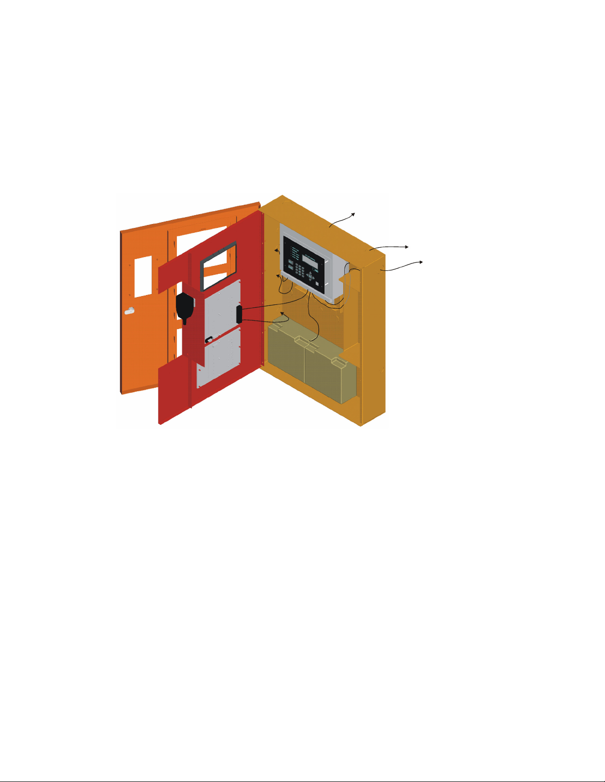
• Route the wiring around the inside perimeter of the cabinet. It should not cross the
circuit board where it could induce noise into the sensitive microelectronics or pick
up unwanted RF noise from the high speed circuits. See Figure 3-1 for an
example.
High frequency noise, such as that produced by the inductive reactance of a speaker
or bell, can also be reduced by running the wire through ferrite shield beads or by
wrapping it around a ferrite toroid.
Figure 3-1 Wire Routing Example
Note: All circuits are power limited except the battery and AC cabling. Maintain 1/4 inch spacing be-
tween high and low voltage circuits and between power-limited and non-power limited circuits.
3-2 LS10062-001-SK-E

Before you Begin Installation
3.3 SBUS Specifications
Refer to Section 4 of the FACP’s installation manual for SBUS wiring details.
EVS-Series Model Number FACP Installation Manual
5820XL-EVS LS10061-001SK-E
3.4 Electrical Specifications
Table 3-1: EVS-50W AC Current Draw
Module Voltage
EVS-50W 25V 120V 60 Hz 350 mA 1100 mA
EVS-50W 70V 120V 60 Hz 350 mA 1200 mA
Table 3-2: EVS-125W AC Current Draw
Module Voltage
EVS-125W 25V 120V 60 Hz 300 mA 2200 mA
Standby
Current
Standby
Current
Alarm
Current
Alarm
Current
LS10062-001-SK-E 3-3

EVS Series Emergency Voice System Installation Manual
3-4 LS10062-001-SK-E

Section 4 EVS Device Installation
Caution!
To avoid the risk of electrical shock and damage to the unit, power should be OFF at the
control panel while installing or servicing.
4.1 Mounting the Cabinet
This section provides instructions on how to install the EVS series cabinet for surface
or recessed mounting. Refer to Section 3.1 when choosing a mounting location.
4.1.1 Preventing Water Damage
Water damage to the fire system can be caused by moisture entering the cabinet
through the conduit. Conduits that are installed to enter the top of the cabinet are
most likely to cause water problems. Installers should take reasonable precautions to
prevent water from entering the cabinet. Water damage is not covered under
warranty.
4.1.2 Surface Mounting
The Cabinet can be mounted on the wall surface by using the mounting holes in the
back of the cabinet (see 4.1).
The EVS-RCU Remote Command Unit is a combination EVS-RVM Remote Voice
Module and its associated 5860 annunciator. The EVS-RCU is compatible with the
Silent Knight 5820XL-EVS. For more information, refer to Installation manual for the
5820XL-EVS (PN LS10061-001SK-E).
Cabinet dimensions are 20" W x 26½” H x 4.6" D.
1. Insert two screws level with each other, 14" apart for the top cabinet key shaped
holes. See Figure 4-1.
2. Hang the cabinet onto the two screws. Tighten the screws down.
3. Insert two screws into the two bottom mounting holes and tighten them snug to
the cabinet.
If you need to remove the cabinet door and the dead front panel, see Section 4.1.3.1
LS10062-001-SK-E 4-1
Loading...