SilentKnight SD500-AIM User Manual

SD500-AIM Input Module and
SD500-MIM Mini Input Module
Installation Instructions
The following instructions are a quick reference guide, refer to the control panel installation manual P/N 151139, 151274, 151280, 151295, 151209, or 151302 for detailed system information.
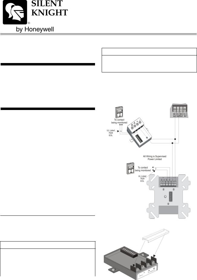
Wiring the SD500-AIM / MIM
Note: Installation and wiring of these devices must be done in accordance with NFPA 72 and local ordinances.
Terminate the wiring as shown in Table 1. See also Figure 1 or Figure 2
Table 1: Wire Connections
SD500-AIM |
|
To: |
|||
|
|
|
|||
SD500-MIM |
|
|
|
||
FACP or SLC |
Contact |
||||
Terminals |
|||||
Loop Terminals |
|||||
|
|
|
|||
|
|
|
|
|
|
|
|
|
|
|
|
SLC |
– |
SLC |
SC– |
|
|
+ |
OUT |
S+ |
|
||
|
|
||||
|
|
|
|
|
|
|
A out |
CLASS A |
To N.O. Contact |
||
Contact |
B out |
OR B |
To N.O. Contact |
||
|
|
|
|
||
A IN |
CLASS A ONLY |
End of Loop A |
|||
|
|||||
|
|
(SD500-AIM Only) |
|
||
|
B IN |
End of Loop B |
|||
|
|
|
|||
|
|
|
|
||
|
|
|
|
|
|
Specifications
Table 2 lists the operating specifications for the SD500-AIM and the SD500-MIM.
Table 2: SD500-AIM and SD500-MIM Specifications
Specifications
|
|
|
Max. Line resistance |
50Ω |
|
|
|
|
Max. Alarm |
One device in alarm |
.5 mA for each addi- |
Current |
23mA. 46 mA for two |
tional device in |
|
devices in alarm. |
alarm. |
|
|
|
Max. Voltage |
|
33 V |
|
|
|
Table 2: SD500-AIM and SD500-MIM Specifications
Specifications
Operating Temperature |
0° to 49° C |
|
(32° to 120° F) |
|
|
Indoor use only |
|
Impedance for Earth Ground Fault is 0 Ω for all terminals.
Figure 1: Class B Wiring the SD500-AIM & SD500-MIM
Alternate
Construction
P/N 151071
 Loading...