


SKE-SERIES
Voice
Evacuation
Installation and
Operations Manual
Part Number 151267 Rev E

Contents
Section 1 |
|
||
Overview ...................................................................................................................................................... |
1-1 |
||
1.1 |
Features .................................................................................................................................................... |
1-1 |
|
1.2 |
Optional Accessories ................................................................................................................................ |
1-2 |
|
1.3 |
About This Manual .................................................................................................................................. |
1-2 |
|
1.4 |
How to Contact Silent Knight .................................................................................................................. |
1-2 |
|
Section 2 |
|
||
Agency Listings, Approvals, and Requirements ................................... |
2-1 |
||
2.1 |
FCC Warning ........................................................................................................................................... |
2-1 |
|
2.2 |
Underwriters Laboratories (UL) .............................................................................................................. |
2-1 |
|
|
2.2.1 Requirements for All Installations .................................................................................................... |
2-1 |
|
|
2.2.2 Requirements for Local Protected Fire Alarm Systems ................................................................... |
2-1 |
|
Section 3 |
|
||
Installation ................................................................................................................................................. |
3-1 |
||
3.1 |
Environmental Specifications .................................................................................................................. |
3-1 |
|
3.2 |
Electrical Specification ............................................................................................................................ |
3-1 |
|
3.3 |
Board Layout ............................................................................................................................................ |
3-2 |
|
|
3.3.1 |
Wiring Overview .............................................................................................................................. |
3-3 |
|
3.3.2 |
Terminal Strip 1 ................................................................................................................................ |
3-4 |
|
3.3.3 |
Terminal Strip 2 ................................................................................................................................ |
3-4 |
|
3.3.4 |
Earth Fault Resistance ...................................................................................................................... |
3-5 |
|
3.3.5 |
System LEDs .................................................................................................................................... |
3-6 |
|
3.3.6 |
Microphone Connection ................................................................................................................... |
3-7 |
|
3.3.7 |
RS-232 Serial Connector .................................................................................................................. |
3-7 |
|
3.3.8 |
Microphone (MIC) Gain ................................................................................................................... |
3-7 |
|
3.3.9 S1 & S2 Message Test Buttons ......................................................................................................... |
3-7 |
|
|
3.3.10 AC Delay Switch .............................................................................................................................. |
3-8 |
|
3.4 |
Mounting the Control Panel ..................................................................................................................... |
3-8 |
|
|
3.4.1 |
Preventing Water Damage ................................................................................................................ |
3-8 |
|
3.4.2 |
Wiring Specifications ....................................................................................................................... |
3-9 |
3.5 |
Mounting the Main Control Board in the Cabinet ................................................................................. |
3-10 |
|
3.6 |
Speaker Wiring ...................................................................................................................................... |
3-11 |
|
|
3.6.1 |
Wiring Lengths ............................................................................................................................... |
3-11 |
|
3.6.2 Class B (Style Y) ............................................................................................................................ |
3-12 |
|
|
3.6.3 Class A (Style Z) ............................................................................................................................. |
3-12 |
|
151267 |
i |

SKE-Series Voice Evacuation System Installation/Operation Manual |
|
||
3.7 |
Input Circuits .......................................................................................................................................... |
3-13 |
|
|
3.7.1 |
CMD1 Input Circuit ........................................................................................................................ |
3-13 |
|
3.7.1.1 Class B (Style Y) .................................................................................................................. |
3-13 |
|
|
3.7.1.2 Class A (Style Z) .................................................................................................................. |
3-14 |
|
|
3.7.2 |
CMD2 Input Circuit ........................................................................................................................ |
3-14 |
3.8 |
Connecting Power .................................................................................................................................. |
3-15 |
|
|
3.8.1 |
AC Power ........................................................................................................................................ |
3-15 |
|
3.8.2 |
Backup Battery Power .................................................................................................................... |
3-17 |
Section 4 |
|
||
Programming ......................................................................................................................................... |
4-1 |
||
4.1 |
DIP Switch Programming ........................................................................................................................ |
4-1 |
|
4.2 |
Recording Custom Message ..................................................................................................................... |
4-3 |
|
|
4.2.1 Input Message 3 From the Microphone ............................................................................................ |
4-4 |
|
|
4.2.1.1 Record Message 3 Using the Microphone ............................................................................. |
4-4 |
|
|
4.2.1.2 To Erase Message 3 ............................................................................................................... |
4-4 |
|
|
4.2.2 Input Message 3 From a PC .............................................................................................................. |
4-4 |
|
|
4.2.2.1 Using the Aux Audio input .................................................................................................... |
4-5 |
|
|
4.2.2.2 Using 7780 Software .............................................................................................................. |
4-6 |
|
Section 5 |
|
||
SKE-ZN4 Zone Splitter ............................................................................................................... |
5-1 |
||
5.1 |
SKE-ZN4 Board and Components ........................................................................................................... |
5-1 |
|
|
5.1.1 |
Terminal Strip 1 ................................................................................................................................ |
5-2 |
|
5.1.2 |
Terminal Strip 2 ................................................................................................................................ |
5-2 |
|
5.1.3 |
Terminal Strip 3 ................................................................................................................................ |
5-2 |
|
5.1.4 |
Terminal Strip 4 ................................................................................................................................ |
5-3 |
|
5.1.5 |
Terminal Strip 5 ................................................................................................................................ |
5-3 |
|
5.1.6 |
Manual Zone Switches ..................................................................................................................... |
5-3 |
|
5.1.7 |
All Call Switch .................................................................................................................................. |
5-4 |
|
5.1.8 |
Zone Supervision Selectors .............................................................................................................. |
5-4 |
|
5.1.9 |
LED Descriptions ............................................................................................................................. |
5-4 |
5.2 |
SKE-ZN4 Specifications .......................................................................................................................... |
5-4 |
|
5.3 |
Mounting the SKE-ZN4 In the SKE-450 Cabinet ................................................................................... |
5-5 |
|
5.4 |
Speaker Wiring ........................................................................................................................................ |
5-7 |
|
|
5.4.1 |
Wiring Procedure .............................................................................................................................. |
5-7 |
|
5.4.2 Class B (Style Y) .............................................................................................................................. |
5-7 |
|
|
5.4.3 Class A (Style Z) ............................................................................................................................... |
5-8 |
|
|
5.4.4 FACP Alarm Zone Control Wiring .................................................................................................. |
5-9 |
|
|
5.4.5 General Alarm Control Wiring ....................................................................................................... |
5-10 |
|
ii |
151267 |

|
|
|
Contents |
Section 6 |
|
||
SKE-ZN6 Six Zone Splitter Installation |
................................................................ 8-1 |
||
6.1 |
SKE-ZN6 Board and Components ........................................................................................................... |
8-1 |
|
|
6.1.1 |
Terminal Strip 1 ................................................................................................................................ |
8-2 |
|
6.1.2 |
Terminal Strip 2 ................................................................................................................................ |
8-3 |
|
6.1.3 |
Terminal Strip 3 ................................................................................................................................ |
8-4 |
|
6.1.4 |
Manual Zone Switches ...................................................................................................................... |
8-4 |
|
6.1.5 |
All Call Switch .................................................................................................................................. |
8-4 |
|
6.1.6 |
LED Descriptions ............................................................................................................................. |
8-4 |
6.2 |
SKE-ZN6 Specifications .......................................................................................................................... |
8-5 |
|
6.3 |
Mounting the SKE-ZN6 In the SKE-450 Cabinet ................................................................................... |
8-5 |
|
6.4 |
Speaker Wiring ........................................................................................................................................ |
8-7 |
|
|
6.4.1 |
Wiring Procedure .............................................................................................................................. |
8-7 |
|
6.4.2 Class B (Style Y) .............................................................................................................................. |
8-8 |
|
|
6.4.3 Class A (Style Z) ............................................................................................................................... |
8-8 |
|
|
6.4.4 FACP Alarm Zone Control Wiring .................................................................................................. |
8-9 |
|
|
6.4.5 General Alarm Control Wiring ....................................................................................................... |
8-10 |
|
Section 7 |
|
||
SKE-SRM ..................................................................................................................................................... |
9-1 |
||
7.1 |
Specifications ........................................................................................................................................... |
9-1 |
|
7.2 |
LED Description ...................................................................................................................................... |
9-2 |
|
7.3 |
Installation Instructions ............................................................................................................................ |
9-2 |
|
|
7.3.1 Mounting the SKE-SRM Cabinet. .................................................................................................... |
9-2 |
|
|
7.3.2 |
Wiring Instructions ........................................................................................................................... |
9-4 |
|
7.3.3 |
Remote Microphone Operation ........................................................................................................ |
9-5 |
Section 8 |
|
||
SKE-V70 Module Installation .......................................................................................... |
10-1 |
||
8.1 |
Mounting ................................................................................................................................................ |
10-1 |
|
8.2 |
Speaker Wiring ...................................................................................................................................... |
10-3 |
|
|
8.2.1 Connecting the SKE-V70 to the Main Control Panel ..................................................................... |
10-3 |
|
|
8.2.2 Class B (Style Y) Wiring to the SKE-V70 ..................................................................................... |
10-4 |
|
|
8.2.3 Class A (Style Z) Wiring to the SKE-V70 ..................................................................................... |
10-4 |
|
|
8.2.4 Connecting the SKE-V70 to the SKE-ZN4 or -ZN6 ...................................................................... |
10-5 |
|
151267 |
iii |

SKE-Series Voice Evacuation System Installation/Operation Manual
Section 9 |
|
Battery Calculation ......................................................................................................................... |
9-1 |
9.1 Calculating Current Draw and Standby Battery ...................................................................................... |
9-1 |
Silent Knight Fire Product Warranty and Return Policy |
|
|
|
iv |
151267 |

Section 1
Overview
This manual contains information on how to install and operate the following voice evacuation controls:
Model Number |
Consists of these Part Numbers |
Where to find Additional |
|
Information |
|||
|
|
||
|
|
|
|
|
|
|
|
SKE-450 |
Main Control Panel |
Section 3 |
|
SKE-450-ZN4 |
Main Control Panel |
Section 3 |
|
|
|
||
SKE-ZN4 |
Section 5 |
||
|
|||
|
|
|
|
SKE-450-ZN6 |
Main Control Panel |
Section 3 |
|
|
|
||
SKE-ZN6 |
Section 6 |
||
|
|||
|
|
|
1.1Features
•50 watt power output
•Built-in Digital Message Repeater (DMR)
•Two programmed 30 second messages, programmable to repeat 3, 4, 6, 8 or infinite number of times
•8 pre-programmed tones
•4 or 6 zone splitter (optional)
•LED indicators for:
Speaker Trouble |
(Yellow LED) |
Alarm |
(Red LED) |
Microphone Trouble |
(Yellow LED) |
Command 2 Trouble |
(Yellow LED) |
Earth Ground Fault |
(Yellow LED) |
Low Battery |
(Yellow LED) |
Power |
(Green LED) |
•Form C Trouble Relay (Common)
•Form C AC Trouble Relay
•Supervised and activated by host fire control system
•Auxiliary audio input
•Supervised Remote Microphone input (Special application for optional SKE-SRM)
•Class A or B speaker supervision
•DIP switch programmable
•UL 864 & 1711 Listed
151267 |
1-1 |

SKE-Series Voice Evacuation System Installation/Operation Manual
1.2Optional Accessories
Part Number |
Description |
SKE-ZN4 |
4 Zone Audio Splitter (see Section 5 for more information) |
SKE-SRM |
Supervised Remote Microphone (see Section 7 for details) |
SKE-ZN6 |
6 Zone Audio Splitter (see Section 6 for more information) |
SKE-V70 |
Converts the speaker circuit voltage from 25 to 70.7 Vrms |
|
(see Section 8 for more information) |
1.3About This Manual
This manual is intended to be a complete reference for all installation and operation tasks. Please let us know if the manual does not meet your needs in any way. We value your feedback!
1.4How to Contact Silent Knight
If you have a question or encounter a problem not covered in this manual, contact Silent Knight Technical Support at 800-446-6444.
To order parts, contact Silent Knight Sales at 800-328-0103 (or 203-484-7161).
1-2 |
151267 |

Section 2
Agency Listings, Approvals, and Requirements
2.1FCC Warning
This device has been verified to comply with FCC Rules Part 15. Operation is subject to the two following conditions: (1) This device may not cause radio interference, and (2) this device must accept any interference received, including interference that may cause undesired operation.
2.2Underwriters Laboratories (UL)
The SKE-450 is UL listed as a voice evacuation unit for use in NFPA 72 systems. If the SKE450 and its accessories are to be used as part of a UL installation, carefully read the UL requirements in this section. For more information on NFPA 72 standards, refer to the NFPA National Fire Alarm Code.
2.2.1Requirements for All Installations
General requirements are described in this section. When installing an individual device, refer to the specific section of the manual for additional requirements.
1.All field wiring must be installed in accordance with NFPA 70, National Electric Code.
2.Use UL listed notification devices with the SKE-450 voice evacuation system.
3.A full system checkout must be performed any time the panel is programmed.
4.UL installations using Class B wiring for the speaker circuit require the use of a Model 7630 EOL resistor assembly.
2.2.2Requirements for Local Protected Fire Alarm Systems
At least one UL-listed, supervised notification appliance must be used.
151267 |
2-1 |
SKE-Series Voice Evacuation System Installation/Operation Manual
This page left blank intentionally.
2-2 |
151267 |
Section 3
Installation
This section of the manual is intended to help you plan your tasks to facilitate the installation. Please read this section thoroughly, especially if you are installing a SKE-450 control for the first time.
3.1Environmental Specifications
It is important to protect the SKE-450 control panel from moisture. To prevent damage, the following conditions should be avoided when installing the units:
•Mount indoors in dry locations only
•Do not mount directly on exterior walls, especially masonry walls (condensation)
•Do not mount directly on exterior walls below grade (condensation)
•Protect from plumbing leaks
•Protect from splash caused by sprinkler inspection ports
•Do not mount in areas with humidity-generating equipment (such as dryers, production machinery)
When selecting a location to mount the panel, it should be mounted where it will NOT be exposed to temperatures outside the range of 0°C-49°C (32°F-120°F) or humidity equal to or greater than 93% at 30°C (89°F) noncondensing.
3.2Electrical Specification
Table 3-1: Electrical Specifications
Circuit |
|
Rating |
|
|
|
|
|
|
Operating Voltage |
120 Vrms @ 60 Hz @ 1.2 amp |
|
|
*230 Vrms @ 50Hz @ .607 amp |
|
|
|
|
Battery Charging Voltage/Circuit |
27.4 VDC @ 1.9A max/ 0.75 avg |
|
|
|
|
Trouble Relays |
2.5 A @ 30 VDC resistive |
|
|
|
|
Minimum Low AC Detect |
92VAC |
25V System |
|
94VAC |
70.7V System |
|
|
|
*Specify voltage requirements when ordering.
Note: Refer to the control panel wiring diagram to determine which power source is required for your control.
151267 |
3-1 |
SKE-Series Voice Evacuation System Installation/Operation Manual
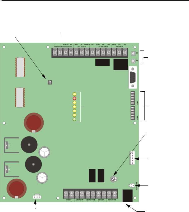
3.3Board Layout
This section of the manual describes the components of the control panel that may be used by the installer or operator.
|
|
SKE-SRM |
Control |
|
Common |
||||
AC Delay |
Remote Microphone |
|
Relay |
||||||
Signals |
|
Outputs |
|||||||
Switch |
|
Terminals* |
|
|
|
|
|
||
|
|
|
|
|
|
||||
|
|
|
|
|
|
|
|
|
|
Terminal Strip 1
System LEDs
Terminal Strip 2
AC Transformer |
|
|
|
|
|
|
|
|
|
|
|
|
|
|
|
Connector |
Alarm |
Speaker Circuit |
|||||
|
Activation |
|
Connections |
||||
Inputs
* Special Applications
Figure 3-1 Board Layout
Message
Test Buttons
RS-232
Connector
Programming
DIPs
Microphone
Gain
Expansion
Connector
Battery Connector
Use Model 6712 Gell
Cell Batteries Replace batteries every 5 years.
Microphone
Connector
3-2 |
151267 |

Installation
3.3.1Wiring Overview
Figure 3-2 provides a basic wiring overview. Refer to the appropriate section in the manual for more information.
Figure 3-2 SKE-450 Wiring Overview
151267 |
3-3 |
SKE-Series Voice Evacuation System Installation/Operation Manual
3.3.2Terminal Strip 1
Table 3-2: Terminal Strip 1 Description
|
Terminal Name |
Comments |
|
|
|
|
|
|
|
|
|
+ |
|
Remote Microphone |
See Section 7.3.2 for details. |
|
|
|
|
- |
|
|
|
|
|
|
|
Active |
|
|
|
|
|
|
|
IN |
|
|
|
|
|
|
|
Neg |
|
Aux Audio (Input) |
For recording custom message only. See Section 4.2.2. |
|
|
|
|
In |
|
|
|
|
|
|
|
Enable |
|
|
|
|
|
|
|
FO |
|
|
Not Used |
|
|
|
|
Com |
|
AC Trouble (Relay) |
Form C energizes when an AC trouble is detected regardless of |
|
|
|
setting of the AC delay switch. |
NC |
|
|
|
|
|
|
|
|
|
|
|
NO |
|
|
|
|
|
|
|
Com |
|
Trouble (Relay) |
Form C common trouble relay |
|
|
|
|
NC |
|
|
|
|
|
|
|
NO |
|
|
|
|
|
|
|
3.3.3Terminal Strip 2
|
|
Table 3-3: Terminal Strip 2 Description |
|
|
|
Terminal Name |
Comments |
|
|
|
|
|
|
|
+ |
CMD2 |
A short across this input will activate message 2. |
|
IN |
|
– |
|
|
|
|
|
+ |
CMD1 |
A reverse polarity trip from the FACP will activate message 1. |
|
IN |
|
– |
|
|
|
|
|
|
|
|
+ |
CMD1 |
|
|
OUT |
|
– |
|
|
|
|
|
+ |
SPK IN |
Used for Class A (Style Z) speaker connections |
|
|
|
– |
|
|
|
|
|
+ |
SPK |
Used for Class B (Style Y) and Class A (Style Z) speaker connections. |
|
OUT |
|
– |
|
|
|
|
|
|
|
|
3-4 |
151267 |
Installation
3.3.4Earth Fault Resistance
Table 3-4 lists the earth fault resistance detection for each applicable terminal on the control panel.
Table 3-4: Earth Fault Resistance Values by Terminal
|
Terminal Name |
Value (in kohms) |
|
|
|
|
|
|
|
|
|
+ |
|
Remote Microphone |
0 |
|
|
|
|
- |
|
|
0 |
|
|
|
|
Active |
|
|
0 |
|
|
|
|
IN |
|
|
0 |
|
|
|
|
+ |
|
CMD2 IN |
0 |
|
|
|
|
– |
|
|
0 |
|
|
|
|
+ |
|
SPK IN |
0 |
|
|
|
|
– |
|
|
0 |
|
|
|
|
+ |
|
SPK OUT |
0 |
|
|
|
|
– |
|
|
0 |
|
|
|
|
151267 |
3-5 |

SKE-Series Voice Evacuation System Installation/Operation Manual
3.3.5System LEDs
The control panel has LEDs which indicate system operation, alarms, and trouble conditions. Table 3-5 lists the LEDs and their function. See also .
Speaker Trouble
Alarm
Mic Trouble
CMD2 Trouble
Earth Ground Trouble
Battery Status
Power
Figure 3-3 System LEDs Close-up View
Table 3-5: LED Descriptions
LED Name |
Color |
Description |
Comments |
|
|
|
|
|
|
|
|
Speaker Trouble |
Yellow |
ON = Speaker circuit trouble |
Trouble relay energized. |
|
|
OFF = Speaker/amp is operating normally |
|
|
|
|
|
Alarm |
Red |
ON = Alarm |
Either CMD1 and/or CMD2 are activated. |
|
|
OFF = No alarms |
|
|
|
|
|
Mic Trouble |
Yellow |
ON = Trouble with on-board microphone |
Trouble relay energized. |
|
|
OFF = Microphone connected |
|
|
|
Flashing = Trouble with remote |
|
|
|
microphone |
|
|
|
|
|
CMD2 Trouble |
Yellow |
ON = Trouble condition with CMD2 |
Trouble relay energized. |
|
|
input, EOL trouble |
|
|
|
OFF = CMD2 operating properly |
|
|
|
|
|
Earth Ground |
Yellow |
ON = Earth Ground Fault detected |
Trouble relay energized. |
|
|
OFF = No Earth Ground Fault detected |
|
|
|
|
|
Battery Status |
Yellow |
ON = Low Battery |
Trouble relay energized. |
|
|
OFF = Battery OK |
|
|
|
|
|
Power |
Green |
ON (Steady) = Power is present |
Trouble relay energized immediately on trouble |
|
|
Flashing = No AC power to the control. |
unless AC Delay is enabled, in which case, trouble |
|
|
|
relay will energize in 2 hours. |
|
|
|
|
3-6 |
151267 |
Installation
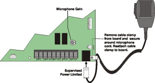
3.3.6Microphone Connection
The microphone connector is used to connect a hand held microphone into the system. The microphone can be used to record a message and as a manual voice evacuation override. See Figure 3-4.
Figure 3-4 Microphone Connection
3.3.7RS-232 Serial Connector
The RS-232 serial connector is used to directly connect the main control to a PC or laptop to up/download custom system messages. See Section 4.2.2.2.
3.3.8Microphone (MIC) Gain
Turn fully clockwise for maximum gain, turn fully counter-clockwise for minimum gain. See Figure 3-4 for Microphone Gain control location.
3.3.9S1 & S2 Message Test Buttons
In normal operating mode you can test CMD 1 and CMD 2 messages by pressing the S1 button (for CMD 1 message) or S2 button (for CMD 2 message). When the S1 or S2 button is pressed for 1 second, the audio message and notification output will begin sounding, simulating an actual CMD input alarm. The message and notification will continue to sound (as programmed) for ten minutes, or you can manually silence them by pressing the same CMD button for 1 second. See Section 4.2 for S1 and S2 functions in recording mode.
151267 |
3-7 |

SKE-Series Voice Evacuation System Installation/Operation Manual
3.3.10 AC Delay Switch
The SKE-450 has two built-in trouble relays – General Trouble and AC Trouble.
The General trouble relay will energize when any trouble condition is detected. If the only trouble condition is an AC failure, the relay output can be programmed to delay the indication by 2 hours by setting the DIP AC Delay Switch 1 to ON. If the AC Delay Switch is in the OFF position the trouble relay will energize immediately when AC power fails. See Figure 3-1 for AC Delay Switch location. The AC Delay Switch may be used only when the SKE-450 is connected to an FACP that uses central station or off premise signaling.
The AC trouble relay will energize when an AC trouble is detected regardless of the settings of the AC delay switch.
3.4Mounting the Control Panel
Read the environmental specifications in Section 3.1 before mounting the control panel cabinet. This will ensure that you select a suitable mounting location.
The panel should be accessible to main drop wiring runs. It should be mounted as close to the center of the building as possible and located within a secured area, but should be accessible for testing and service.
Mount the control panel cabinet so it is firmly secured to the wall surface. When mounting on concrete, especially when moisture is expected, attach a piece of 3/4-inch plywood to the concrete surface and then attach the cabinet to the plywood. Also mount any other modules to the plywood.
The cabinet can be surface or flush-mounted. If you will be flush-mounting the cabinet, the hole for the enclosure should be 14.5" W x 24.75" H x 3-7/16" D (36.8cm W x 62.9cm H x 8.73cm D). Do not flush-mount in a wall designated as a fire break.
3.4.1Preventing Water Damage
Water damage to the fire system can be caused by moisture entering the cabinet through the conduits. Conduits that are installed to enter the top of the cabinet are most likely to cause water problems. Installers should take reasonable precautions to prevent water from entering the cabinet. Water damage is not covered under warranty.
3-8 |
151267 |
Installation
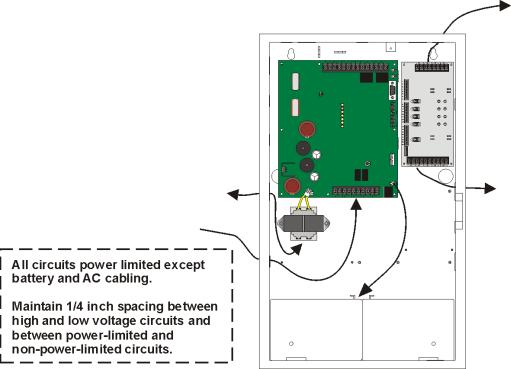
3.4.2Wiring Specifications
The maximum line resistance of the wire run from FACP to voice evacuation control system is 50W. All wiring and devices installed in the system must meet the standards described in National Electrical Code (NFPA 70), NFPA Standard 72, and Life Safety Code (NFPA 101).
To avoid induced noise (transfer of electrical energy from one wire to another), keep input wiring isolated from high-current output and power wiring. Avoid pulling one multiconductor cable for the entire panel. Instead, separate the wiring as follows:
Table 3-6
1/4" spacing must be maintained |
Input/Output Type |
Wiring |
between each of these circuit types; |
|
|
Non Power-Limited: |
AC power, Standby batteries |
|
as well as between power limited |
|
|
Power-Limited: |
Notification devices, SKE-SRM, and Relays |
|
and non power-limited circuits. |
|
|
Audio: |
Speaker |
|
|
|
|
DO NOT pull wires from different groups through the same conduit.
For the same reasons, wiring within the cabinet should be routed around the perimeter of the cabinet. It should not cross the printed circuit board where it could induce noise into the sensitive microelectronics or pick up unwanted RF noise from the high speed circuits.
High frequency noise, such as that produced by the inductive reactance of a speaker or bell, can also be reduced by running the wire through ferrite beads or by wrapping it around a ferrite toroid core. Figure 3-5 provides an example.
Speaker
To AC |
Speaker |
CMD Inputs
Battery Cable
Figure 3-5 Wire Routing Example
151267 |
3-9 |
SKE-Series Voice Evacuation System Installation/Operation Manual
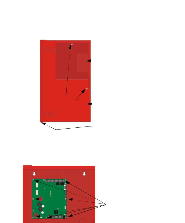
3.5Mounting the Main Control Board in the Cabinet
Follow these steps to properly install the main control board into the cabinet:
1.Unlock and open the cabinet door.
2.Remove the two cover plate retaining screws, then open the control panel cover plate. See Figure 3-6.
Zone Splitter

 Access Plate
Control Panel |
|
Control Panel |
Cover Plate |
|
|
|
Cover Plate |
|
|
||
Retaining Screws |
|
|
|
|
Hinge Screw
Figure 3-6 View of Cabinet With Cover Plate in Place
Note: The control panel cover plate can be remove by removing the Hinge screw.
3.Run all wire needed to install the system at this time. See Sections 3.6 and 3.7.
4.Mount the main control board into the cabinet as shown in Figure 3-7.
Main Control
 Chassis Mounting
Screws
Figure 3-7 Main Control Board Mounting Location
5. Connect wiring as described in Sections 3.6, 3.7, and 3.8.
3-10 |
151267 |
Installation
3.6Speaker Wiring
Each SKE-450 supplies one NAC (Notification Appliance Circuit) for speaker connection. The speaker circuit can be supervised and wired Class B (Style Y) or Class A (Style Z). The speaker circuit is capable of 50 watts of power at 25 Vrms or 70.7 Vrms (using the SKE-V70 Module, see Section 8 for SKE-V70 installing instructions).
Note: If the SKE-V70 Module is installed, all speaker wiring must be separated by a minimum of 1/4” from the low voltage wiring, and must exit the cabinet through its own opening.
3.6.1Wiring Lengths
Table 3-7
Number Of Speakers |
Total Load |
|
Wire Distance in Feet |
|
||||
|
|
|
|
|
|
|
|
|
@1/2 W |
@1 W |
Vrms |
Watts |
18 AWG |
16 AWG |
14 AWG |
12 AWG |
|
|
|
|
|
|
|
|
|
|
|
|
|
|
|
|
|
|
|
10 |
5 |
25Vrms |
5W |
3900 |
6200 |
9860 |
15680 |
|
70Vrms |
25000 |
39700 |
63200 |
100520 |
||||
|
|
|
||||||
|
|
|
|
|
|
|
|
|
20 |
10 |
25Vrms |
10W |
2125 |
3380 |
5375 |
8540 |
|
70Vrms |
15200 |
24150 |
38400 |
61100 |
||||
|
|
|
||||||
|
|
|
|
|
|
|
|
|
30 |
15 |
25Vrms |
15W |
1460 |
2320 |
3690 |
5870 |
|
70Vrms |
11000 |
17500 |
27800 |
44200 |
||||
|
|
|
||||||
|
|
|
|
|
|
|
|
|
40 |
20 |
25Vrms |
20W |
1100 |
1750 |
2780 |
4420 |
|
70Vrms |
8500 |
13510 |
21500 |
34175 |
||||
|
|
|
||||||
|
|
|
|
|
|
|
|
|
52 |
26 |
25Vrms |
26W |
760 |
1200 |
1920 |
3050 |
|
70Vrms |
6100 |
9700 |
15400 |
24520 |
||||
|
|
|
||||||
|
|
|
|
|
|
|
|
|
80 |
40 |
25Vrms |
40W |
550 |
875 |
1390 |
2200 |
|
70Vrms |
4100 |
6500 |
10360 |
16480 |
||||
|
|
|
||||||
|
|
|
|
|
|
|
|
|
100 |
50 |
25Vrms |
50W |
450 |
715 |
1130 |
1800 |
|
70Vrms |
3500 |
5560 |
8850 |
14070 |
||||
|
|
|
||||||
|
|
|
|
|
|
|
|
|
Note: The above table assumes a uniform distribution of the speakers, and that a max of 20% voltage drop on the last speaker is allowed.
151267 |
3-11 |
SKE-Series Voice Evacuation System Installation/Operation Manual
3.6.2Class B (Style Y)
Figure 3-8 illustrates how to wire speakers to the control panel using Class B (Style Y) supervision.
Supervised
Power Limited
15 kΩ EOL
UL Listed Model 7630
Figure 3-8 Class B (Style Y) Speaker Configuration
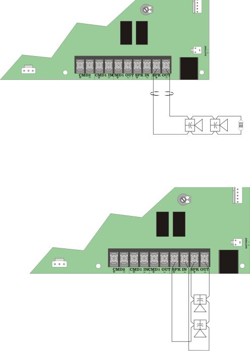
3.6.3Class A (Style Z)
Figure 3-9 illustrates how to wire speakers to the control panel using Class A (Style Z) wiring.
Supervised 


Power Limited
Figure 3-9 Class A (Style Z) Speaker Configuration
3-12 |
151267 |
Installation
3.7Input Circuits
The SKE-450 has two command input circuits (CMD1 & CMD2). The command input circuits are used to activate the amplifier that transmits the audio signal over the output speakers.
3.7.1CMD1 Input Circuit
This section describes how to connect Class B (Style Y) or Class A (Style Z) inputs to CMD1 terminals. CMD1 input circuit rating is 12 to 30 VDC @ 50 mA. CMD1 is a polarity reverse input to activate and supervise the SKE-450
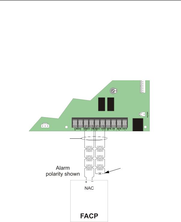
3.7.1.1Class B (Style Y)
Figure 3-10 illustrates how to wire a Class B (Style Y) input circuit to CMD1 input.
Supervised
Power Limited
If a trouble condition exists on the SKE-450, the supervision circuit is opened in addition to energizing the trouble relay causing a trouble at the FACP.
4.7 kΩ EOL
 UL Listed Model 7626
Note: The 4.7 kΩ EOL is typically used with Silent Knight Controls. Check the Installations Manual of the FACP you are using to determine EOL value.
Figure 3-10 Class B (Style Y) CMD1 Input Circuit Configuration
151267 |
3-13 |
 Loading...