

Siemens 7XV5652-0xA00 Series, 7XV5652-0AA00 Operating Instructions Manual
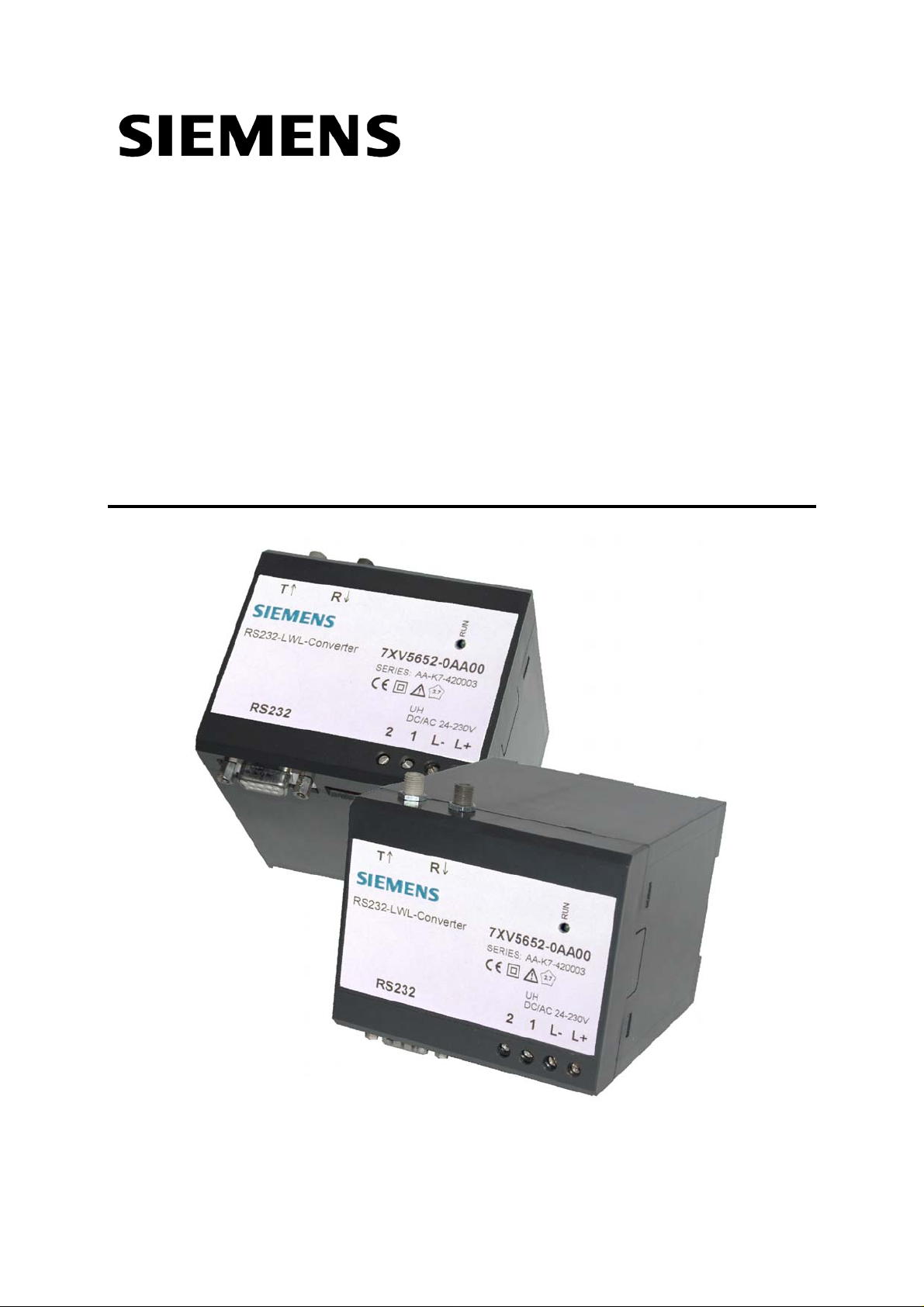
RS232-FO Converter
7XV5652-0xA00
Operating Instructions
Oct. 2006


Table of content
1 GENERAL INSTRUCTIONS...........................................................................................................4
1.1 Qualified Personnel.....................................................................................................................5
1.2 Safety Notes................................................................................................................................6
1.3 Intended Use...............................................................................................................................7
1.4 Explanation of the symbols at the device:...................................................................................7
1.5 Exclusion of liability .....................................................................................................................8
1.6 Copyright.....................................................................................................................................8
2 OPERATING INSTRUCTIONS .......................................................................................................9
2.1 Scope of Application....................................................................................................................9
2.2 General Data...............................................................................................................................9
2.3 Data Transfer.............................................................................................................................10
2.4 Connection of the FO Channel..................................................................................................10
2.5 Connection of the RS 232 Channel...........................................................................................10
2.6 Terminal Assignment 7XV5100-4 .............................................................................................10
3 TECHNICAL DATAS.....................................................................................................................11
3.1 Hardware features....................................................................................................................11
3.2 Safety Tests...............................................................................................................................12
3.3 Dielectric Tests..........................................................................................................................13
3.4 Interference Emission................................................................................................................13
3.5 Interference immunity................................................................................................................14
3.6 Climatic Stress tests..................................................................................................................15
3.7 Mechanical Stress Tests...........................................................................................................16
3.8 Dimension Drawings .................................................................................................................18
3.9 Ordering Data............................................................................................................................18
4 DESCRIPTION OF THE FUNCTIONAL UNIT..............................................................................19
4.1 General description...................................................................................................................19
4.2 Terminal Assignment........................................................................................................
4.3 Pin assignment X1, X2, X5........................................................................................................20
4.4 Switch positions.........................................................................................................................21
5 INSTALLATION AND COMMISSIONING ....................................................................................22
5.1 Reference to Installation............................................................................................................22
5.2 Connection ................................................................................................................................22
5.2.1 Voltage for operation – Auxilliary voltage.........................................................................23
5.2.2 Alarm relay terminals X5...................................................................................................23
5.2.3 Fibre Optic (FO) connections ...........................................................................................23
5.2.4 RS232 connection ............................................................................................................24
5.3 Commissioning..........................................................................................................................24
5.4 Maintenance..............................................................................................................................24
.........19
6 APPLICATIONS............................................................................................................................25
6.1 Optical star-structur for devices V3 with RS232-Interface........................................................25
6.2 Data communication for Digital Differential Protection Relays with FO-Interface.....................26
12.10.2006 RS232-FO Converter Page 3 of 28

1 General Instructions
This manual includes the information required for the normal use of the
products described therein. It is intended for technically qualified
personnel which has been specially trained or has special knowledge in
the fields of protection-, instrumentation-, control-, and automatic control
engineering (called automation in the following).
The knowledge and the technically correct translation of the safety
instructions and warnings included in this manual are a prerequisite for
the safe installation and commissioning, as well as for safety during
operation and maintenance, of the product described. Only qualified
personnel, as defined in the following explanation, possess the technical
knowledge required to interpret correctly and to put into action for each
individual case the safety instructions and warnings given in this
document in a general manner.
This manual is an integral part of the scope of delivery. However, it
cannot take into account every detail on all types of the described
product and also every possible case regarding installation, operation or
maintenance. If further information is desired or in case special problems
should arise, which are not treated adequately in this document, it is
possible to obtain additional details from the local Siemens office or from
the addresses stated in the back of this manual.
Additionally, we point out that the content of this product documentation
is not part of or modifies any previous or existing agreement, promise, or
legal relationship.
All obligations by Siemens result from the respective purchase order
which also includes the complete and exclusively valid warranty
provision. The contractual warranty regulations are neither extended nor
limited by the statements in this document.
Page 4 of 28 RS232-FO Converter 12.10.2006

1.1 Qualified Personnel
Tampering with the device/system or noncompliance with the safety
notices given in this manual may cause severe bodily injury or property
damage. Therefore any interventions on the device/system may only be
performed by adequately qualified personnel.
Qualified personnel as per the safety notices given in these instructions
or on the product itself is:
• personnel involved in planning and configuration activities and familiar
with the safety concepts used in automation engineering;
• operating personnel trained for working with automation systems and
familiar with the content of this manual as far as it deals with operational
aspects;
• commissioning and service personnel having adequate training and
qualification to repair this type of automation equipment and/or having
authorization to commission, release, ground and tag devices, systems
and electrical circuits.
12.10.2006 RS232-FO Converter Page 5 of 28
1.2 Safety Notes
These operating instructions contain notes that are to be complied with
for your personal safety as well as to avoid property damages. These
notes are marked by a triangular warning symbol and the different
degrees of danger are categorized as follows:
Danger
Disregard of the corresponding precautionary
measures will cause death, severe bodiliy injury or
considerable property damage.
Warning
Disregard of the corresponding precautionary
measures may cause death, severe bodiliy injury
or considerable property damage.
Attention
Disregard of the corresponding precautionary
measures may lead to slight bodiliy injury or minor
property damage
Note
Shall draw your attention to special information on
the product, product handling or the corresponding
section of the documentation.
Qualified personnel
Commissioning and operation of the equipment is
to be performed by qualified personnel only. In the
context of safety notes in this manual, the term
qualified personnel refers to persons authorized to
perform commissioning, grounding and labelling of
devices, systems and electrical circuits.
Page 6 of 28 RS232-FO Converter 12.10.2006
1.3 Intended Use
Please observe the following
Warning
The device must be operated only within the scope
of its intended use according to these operating
instructions and in connection with third-party
equipment or compounds recommended or
accepted by Siemens.
Faultless and safe operation of the product require
proper transport, storage, mounting and installation
as well as careful operation and maintenance.
1.4 Explanation of the symbols at the device:
Danger
Warning of a danger.
Please read the documentation.
To be operated only by qualified personnel.
Double insulation
12.10.2006 RS232-FO Converter Page 7 of 28

1.5 Exclusion of liability
The contents of this document have been reviewed on their compliance
with the hardware and software described therein. Yet, deviations cannot
be excluded, so that we cannot guarantee full compliance. The
specifications in this document are, however, reviewed at regular
intervals. Necessary corrections will be included in the next edition. You
are invited to send us your suggestions for improvement.
1.6 Copyright
Copyright Siemens AG 2000. All rights reserved.
Transmission or reproduction of this document, as well as the use and
forwarding of its contents is not permitted without express written
authority. Offenders will be liable for damages. All rights, including rights
created by patent grant or registration of a utility model or design, are
reserved.
Subject to technical changes without notice.
Page 8 of 28 RS232-FO Converter 12.10.2006

2 Operating Instructions
2.1 Scope of Application
The RS232 / FO Converter is used for converting RS232 signals to
signals for FO conductors with BOFC ST-connectors. It is equipped with
one FO channel and one RS232 channel and switches automatically
from ”FO receiving data” to ”FO transmitting data”.
A power supply is integrated in the housing to generate the voltage
required for the converter board from the auxiliary power supply.
The RS232 / FO converter can be used for transmission rates up to
115200 bauds.
2.2 General Data
The signal converter has a plastic housing that can be snapped onto a
DIN EN 50022 mounting rail.
The auxiliary power supply is fed in via two terminals. Because of ist
extremely wide auxiliary voltage range (DC 24-250V and AC 60-250V),
the converter can be connected without switchover to all common types
of station batteries and AC mains voltage supplies.
The front cover has a green LED for indication of the operating voltage
status. The status of the internal +5V operating voltage can be checked
by means of a potential-free relay contact that is brought out to two
terminals. An open contact means that the operating voltage is o.k. The
readiness for service of the unit is indicated by means of a potential-free
signalling contact (terminals 1,2) that can be used to communicate the
following fault conditions to a control center:
• No supply voltage
• Failure of internal power supply
When a fault condition is present, the contact is closed.
12.10.2006 RS232-FO Converter Page 9 of 28
 Loading...