

Siemens 7XV5550-0xA00 Series Manual
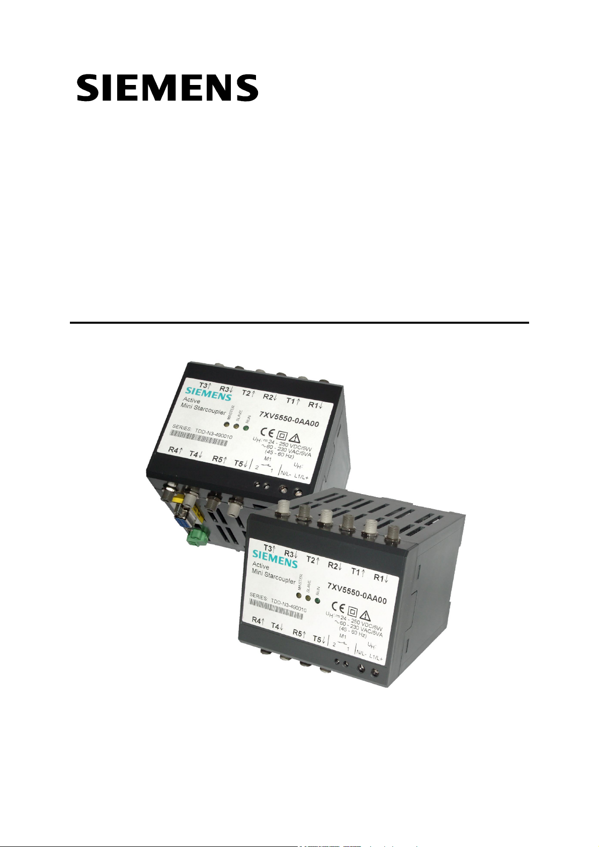
Active Mini-Starcoupler
7XV5550-0xA00
Manual
Jan. 2002


Table of content
1 APPLICATION AND SHORT FUNCTIONAL DESCRIPTION........................................................ 9
1.1 Technical features..................................................................................................................... 10
1.1.1 Interfaces.......................................................................................................................... 10
1.1.2 Setting parameters ........................................................................................................... 11
1.1.3 Master and Slave-interfaces............................................................................................. 11
1.1.4 Master-interfaces ............................................................................................................. 12
1.1.5 Slave-interfaces................................................................................................................ 12
1.1.6 Baudrates ......................................................................................................................... 12
1.1.7 Data format ...................................................................................................................... 12
1.1.8 Channel selection during the operation............................................................................ 12
1.1.9 Disconnection between Master- and Slave-interface ....................................................... 13
1.1.10 Internal memory for the data-transfer............................................................................... 13
1.1.11 Cascading several Mini-Starcouplers............................................................................... 14
1.1.12 Mini-Starcoupler as Master-device................................................................................... 14
1.1.13 Further Mini-Starcouplers as Slave-devices..................................................................... 14
2 TECHNICAL DATAS .................................................................................................................... 15
2.1 Hardware features ................................................................................................................... 15
2.2 Safety Tests .............................................................................................................................. 16
2.3 EMC tests ................................................................................................................................. 17
2.4 Mechanical Stress Tests........................................................................................................... 18
2.5 Climatic Stress tests ................................................................................................................. 18
2.6 Dimensions ............................................................................................................................... 19
3 ORDERING CODE........................................................................................................................ 19
4 DESCRIBTION OF THE DEVICE AND IT´S INTERFACES ........................................................ 20
4.1 General description................................................................................................................... 20
4.2 Position and assignment of the terminals................................................................................. 20
4.2.1 Auxilliary voltage X2 ......................................................................................................... 20
4.2.2 Alarm contact X7 .............................................................................................................. 20
4.2.3 Optical interfaces Tx/Rx ...................................................................................................20
4.2.4 RS232 Operating Interface X1 ......................................................................................... 21
4.2.5 RS485- Cascading Interface X5....................................................................................... 22
4.2.6 DIP-Switches S1 and S2 .................................................................................................. 22
4.3 Terminal Assignment................................................................................................................ 23
4.3.1 Auxilliary voltage terminals X2 ......................................................................................... 23
4.3.2 Alarm relay terminals (Live contact) X7 ........................................................................... 23
4.3.3 RS232-Interface X1.......................................................................................................... 23
4.3.4 RS485-Interface X5.......................................................................................................... 24
4.4 LED's......................................................................................................................................... 24
4.4.1 Green LED "RUN" ............................................................................................................24
4.4.2 Yellow LED "MASTER" .................................................................................................... 24
4.4.3 Yellow LED "SLAVE"........................................................................................................ 24
4.5 Setting of the DIP-switches....................................................................................................... 25
14.01.2002 Active Mini-Starcoupler Page 3 from 52

5 INSTALLATION AND COMMISSIONING .................................................................................... 26
5.1 Reference to Installation ...........................................................................................................26
5.2 Connection................................................................................................................................ 26
5.2.1 Voltage for operation – Auxilliary voltage ......................................................................... 27
5.2.2 Alarm relay terminals X7 .................................................................................................. 27
5.2.3 Fibre Optic (FO) connections ........................................................................................... 27
5.2.4 RS232 connection ............................................................................................................ 28
5.2.5 Commissioning................................................................................................................. 28
5.3 Maintenance.............................................................................................................................. 28
6 MODES OF OPERATION.............................................................................................................29
6.1 How to activate the operation mode ......................................................................................... 29
6.1.1 How to select the Active Transmission Mode .................................................................. 29
6.1.2 Passiv Transmission Mode .............................................................................................. 30
6.1.3 Termination of the Active Transmission MOde ................................................................ 30
6.1.4 Time out conditions ..........................................................................................................30
6.1.5 Test aid for the data connection ....................................................................................... 31
6.2 Activation of the Setting Mode .................................................................................................. 31
6.2.1 With DIGSI – cable 7XV5100-4 (Bridged between pin 7-8) ............................................ 31
6.2.2 With Zero-Modem Cable (Not bridged between pin 7-8) .................................................32
6.2.3 With standard parameters 9600 Baud, 8N1 (recommended).......................................... 32
6.3 Setting of the interfaces ............................................................................................................ 33
6.3.1 With the terminal program "Hyper-Terminal" ................................................................... 33
6.3.2 The main setting dialogue / Change language................................................................. 34
6.3.3 Changing the parameters of a port (interface) ................................................................. 35
6.3.4 Saving parameters ........................................................................................................... 38
6.3.5 Termination of the Setting mode...................................................................................... 38
7 CHANGE THE FIRMWARE IN THE DEVICE............................................................................... 39
7.1 Warnings................................................................................................................................... 39
7.2 How to change the firmware ..................................................................................................... 39
8 APPLICATIONS TOGETHER WITH SIPROTEC RELAYS ......................................................... 40
8.1 SIEMENS-Relays of version 1/2 together with DIGSI V3 ......................................................... 40
8.1.1 Functional limitations with V1 / V2 protection devices...................................................... 44
8.2 SIEMENS-Relays of version 1/2 and 3 together with DIGSI V3 .............................................. 45
8.2.1 Operation with DIGSI 4.3x................................................................................................ 46
8.3 SIEMENS-Relays of version 1/2/3 and SIPROTEC 4 relays together with
DIGSI V3 or DIGSI 4................................................................................................................. 48
8.3.1 Operation with DIGSI 4.3x................................................................................................ 49
Page 4 from 52 Active Mini-Starcoupler 14.01.2002

General Instructions
This manual includes the information required for the normal use of the
products described therein. It is intended for technically qualified
personnel which has been specially trained or has special knowledge in
the fields of protection-, instrumentation-, control-, and automatic control
engineering (called automation in the following).
The knowledge and the technically correct translation of the safety
instructions and warnings included in this manual are a prerequisite for
the safe installation and commissioning, as well as for safety during
operation and maintenance, of the product described. Only qualified
personnel, as defined in the following explanation, possess the technical
knowledge required to interpret correctly and to put into action for each
individual case the safety instructions and warnings given in this
document in a general manner.
This manual is an integral part of the scope of delivery. However, it
cannot take into account every detail on all types of the described
product and also every possible case regarding installation, operation or
maintenance.
If further information is desired or in case special problems should arise,
which are not treated adequately in this document, it is possible to
obtain additional details from the local Siemens office or from the
addresses stated in the back of this manual.
Additionally, we point out that the content of this product documentation
is not part of or modifies any previous or existing agreement, promise,
or legal relationship.
All obligations by Siemens result from the respective purchase order
which also includes the complete and exclusively valid warranty
provision.
The contractual warranty regulations are neither extended nor limited
by the statements in this document.
14.01.2002 Active Mini-Starcoupler Page 5 from 52
Safety Notes
These operating instructions contain notes that are to be complied with
for your personal safety as well as to avoid property damages. These
notes are marked by a triangular warning symbol and the different
degrees of danger are categorized as follows:
Danger
Disregard of the corresponding precautionary
measures will cause death, severe bodiliy injury or
considerable property damage.
Warning
Disregard of the corresponding precautionary
measures may cause death, severe bodiliy injury
or considerable property damage.
Attention
Disregard of the corresponding precautionary
measures may lead to slight bodiliy injury or minor
property damage
Note
Shall draw your attention to special information on
the product, product handling or the corresponding
section of the documentation.
Qualified personnel
Commissioning and operation of the equipment is
to be performed by qualified personnel only. In the
context of safety notes in this manual, the term
qualified personnel refers to persons authorized to
perform commissioning, grounding and labelling of
devices, systems and electrical circuits.
Page 6 from 52 Active Mini-Starcoupler 14.01.2002
Intended Use
Please observe the following
Warning
The device must be operated only within the scope
of its intended use according to these operating
instructions and in connection with third-party
equipment or compounds recommended or
accepted by Siemens.
Faultless and safe operation of the product require
proper transport, storage, mounting and installation
as well as careful operation and maintenance.
Explanation of the symbols at the device:
Danger
Warning of a danger.
Please read the documentation.
To be operated only by qualified personnel.
Double insulation
Exclusion of liability
The contents of this document have been reviewed on their compliance
with the hardware and software described therein. Yet, deviations cannot
be excluded, so that we cannot guarantee full compliance. The
specifications in this document are, however, reviewed at regular
intervals. Necessary corrections will be included in the next edition. You
are invited to send us your suggestions for improvement.
14.01.2002 Active Mini-Starcoupler Page 7 from 52

Copyright
Copyright Siemens AG 2000. All rights reserved.
Transmission or reproduction of this document, as well as the use and
forwarding of its contents is not permitted without express written
authority. Offenders will be liable for damages. All rights, including rights
created by patent grant or registration of a utility model or design, are
reserved.
Subject to technical changes without notice.
Version changes:
First issued on 08.02.2001
Changes introduced on 14.01.2002:
• 6.3.3 Timeout-time 00:00:00 (infinite) cancelled.
• Page 37 Timeout-times must be graded.
• 8.1.1 Functional limitations of protection devices V1/2
• 8.2.1 Operation with DIGSI 4.3x
Page 8 from 52 Active Mini-Starcoupler 14.01.2002

1 Application and short functional description
The Active Mini-Starcoupler is designed for universal use in applications
with serial interfaces, where one or several devices with different serial
baudrate and data frame shall be linked together. It´s an active, serial
port-switcher, where you can switch from one or more selectable input
interfaces (Master interfaces) with an ASCII sequence to one output
interface (Slace interface). With a terminal program or a customer
specific software on a PC, 128 Slave-interfaces can be selected from a
central unit (normally a PC) and the communication between the central
unit and the device runs over the port-switcher. At each Slave-interface
one not addressable device or several by protocol addressable devices
can be connected. Even the remote control via a modem connected to a
Master-interface is possible. For each Slave-interface a channel number
is parametrized in the Active Mini-Starcoupler. Furthermore the serial
data format, the baudrate and the data frame can be set individually for
each Slave-interface.
No hardware handshake for the serial interfaces is supported. The datatraffic between the master unit at the Master-interface to the devices at
the Slave-interfaces must be controlled by a user defined protocol (e.c.
protocol with device addresses or ASCII-protocol with XON/XOFF
sequences).
Through the wide range power supply, which allows the connection to all
common types of AC voltage supplies (AC: 110V / 230V) and DC
batteries (DC: 24V –250V) and through the electromagnetic, disturbance
free optical interfaces, the Active Mini-Starcoupler has favourite design
features for the use in the industrial field and for serial applications
together with protection and substatation control.
It allows the central and remote interrogation :
- Of non-addressable devices. Each at one Slave-interface (e.c.
devices with ASCII – protocol like relays of version 1 or 2 from
SIEMENS).
- Of several addressable devices with common interface parameters
on one Slave-interface (Over protocol identified devices like relays
of version 3 and 4 from SIEMENS)
- Common operation with non–addressable and addressable devices
in a communication topology from a master unit.
- Of devices with different baudrate and data frame.
14.01.2002 Active Mini-Starcoupler Page 9 from 52

1.1 Technical features
• One local RS232 interface with 9 pole Sub-D socket for the setting
procedure or for normal data exchange. The interface don´t support
hardware handshake during normal operation. Only in a special
setting mode the hardware handshake is provided.
• 5 optical duplex interfaces (transmit and receive connector) for the
connection to multimode fibre optic cables (FO) with FSMA- or ST
plugs. The data-exchange must be realized in a half-duplex mode
with a continuous data stream of less than 254 Byte (max. bytelength for one continuous data stream in one direction).
• Settable idle state ´Light ON´ or ´Light OFF´ for each of the optical
interfaces. Factory setting is ´Light OFF´. This state is equal with
those of the optical interfaces from relays from SIEMENS.
• Wave length of the optical interfaces is 820 nm.
• The maximum distance between devices connected optically with
multimode-FO (62,5/125 µm) is 1,5 km (approx. 1 mile).
• Individually settable async. baud rates of 1200, 2400, 4800, 9600,
19200, 38400, 57600 und 115200 Baud for each interface.
• Individually settable data frames 8N1, 8N2 und 8E1 for each
interface.
• Wide range power supply with 24 V – 250 V DC
and 110 / 230 V AC.
• LED indication for operation and date transfer from the Master to
the Slave-interface..
• One RS485-interface for cascading in a half-duplex-mode between
several Active-Mini-Starcouplers. Transmitting and receiving datas
at the same time is not possible via this interface.
• Through cascading the whole configuration can be extended up to
128 Slave-interfaces.
• Plastic housing for 35 mm top-hat rail mounting.
1.1.1 Interfaces
The Active Mini-Starcoupler has at it´s bottom side a 9 pole RS232
interface. This interface is used for parametrization and for central local
access from a PC.
Page 10 from 52 Active Mini-Starcoupler 14.01.2002

At it´s front side five optical interfaces with a transmit (Tx) and receive
(Rx) connector as FSMA- or ST-type are located. This interfaces allow
an interference free connection to the optical interfaces of further Active
Mini-Starcouplers or optical interfaces of devices / relays. The light idle
state ON or OFF for each optical interface can be set by a terminal
program in the Active Mini-Starcoupler by software.
For the cascading of Active Mini-Starcouplers it has at the bottom side a
serial RS485 bus-interface, where several devices can communicate via
an elecrical half duplex two wire RS485 bus. The bus termination
resistance is set with a DIP-switch to ON or OFF. For the first and last
device at the RS485 bus it must be set to ON, OFF for the other devices
between.
1.1.2 Setting parameters
The setting of parameters work by a simple terminal program (e.g.
Hyperterm from WINDOWS®) via the DIGSI – cable 7XV5100-4, which
connects the RS232 interface from the Active Mini-Starcoupler with one
serial PC-interface. The programming dialogue runs in the terminal
program and the paramerters stored in the device. English and German
is available for this setting dialogue. No special operational software is
required.
If the switch S2.1 is set to ON, the setting dialogue runs with 9600 Baud
(baudrate) and 8N1 (data format) after switching OFF and ON the power
supply of the device, even the interface has been set to Master-mode
and therefore may have other interface parameters. 8N1 and 9600 Baud
have to be set in the terminal program for the PC interface connected
with the device. After switching ON the power supply, with S1.1 in ON
state, the device is in the setting mode. If the datas of the serial interface
remain unchanged during this setting procedure, they are valid again
with there existing values, when the setting mode is left by the user.
Parameters are stored unerasable against loss of power supply in an
2
E
PROM in the device.
1.1.3 Master and Slave-interfaces
All interfaces can be set as Master or Slave interface. All Masterinterfaces must have the channel number zero. The Slave-interfaces are
set to a channel number between 1 and 254. Via an ASCII – sequence
the channel is selected and afterwards the data traffic is switched from
the Master to the selected Slave-interface.
14.01.2002 Active Mini-Starcoupler Page 11 from 52

1.1.4 Master-interfaces
In one device more than one interface can work as Master-interface, set
all with channel number zero. If several interfaces are set as Masterinterfaces, they must have the same interface properties like data frame
and baudrate. All received datas at one Master-interface are transmitted
with the same data frame and baudrate to the other Master-interfaces of
the device and Master-interfaces of cascaded devices.
1.1.5 Slave-interfaces
All interfaces, which have been as Slave-interfaces, must be
programmed with a unique channel number between 1 and 128. It´s not
allowed to have equal channel numbers for Slave-interfaces in a
topology of serveral devices, which is e.g. cascaded via the RS485
interface or a Master-interface. Each Slave-interface can have it´s
individual baudrate and data format.
1.1.6 Baudrates
All interfaces can set to 1200, 2400, 4800, 9600, 19200, 38400, 57600
und 115000 Baud.
1.1.7 Data format
All interfaces can set to:
8N1 (1 Start bit, 8 data bits, No parity bit, 1 Stop bit),
8N2 (1 Start bit, 8 data bits, No parity bit, 2 Stop-bits) and
8E1 (1 Start bit, 8 data bits, Even parity bit, 1 Stop-bits).
1.1.8 Channel selection during the operation
Slave-interfaces must be selected via the Master-interface with a
channel selection command during normal operation. This switches an
active data connection between Master- and Slave-interface for the
serial data traffic. The entry for the selected channel number (one out of
1-128) is done in the terminal program during the operation mode beside
the Prompt REMOTE> and terminated with a RETURN.
REMOTE>2 <CR – Carrige RETURN> selects channel number 2
If the selected channel number has been identified by the Active MiniStarcoupler and the channel is routed from the Master- to the Slave-port
successfully, the device is in an Active Transmission Mode and answers
to the terminal program or the application software with:
Page 12 from 52 Active Mini-Starcoupler 14.01.2002

REMOTE>Connected to port # 3
To deselect type BYE
All Master-interfaces are routed to the selected Slave-interface, e.g. the
Active Mini-Starcoupler transforms baudrate and data frame according
the settings for those interfaces. Only one active connection can be
opened at the same time. All other Slave-interfaces are not connected
and in an passive mode. Received datas at the Master-interface are
send only to all other connected Master-interfaces and the selected
Slave-interface.
After the Ative Transmission Mode is activated the operational software
e.g. DIGSI is started on the PC. This software exchange serial datas
between the PC and the serial interface of a device, which has been
connected to the Slave-interface of the Active Mini-Starcoupler. This
data transfer runs via the Master- and Slave-interface of the Active MiniStarcoupler, where it transforms the serial datas.
After the PC software application is finished, the connection between
Master- and Slave-interface should be terminated. This can be done by
the software, if the disconnection string is implemented in the software
(e.g. DIGSI 3). If not, it can be done again with the terminal program.
A timeout set for the interfaces also leads to an automatic release of the
Active Transmission Mode. If within the timeout duration no datas are
exchanged Master- and Slave-interface get disconnected.
1.1.9 Disconnection between Master- and Slave-interface
After the entry of ´BYE´ (without RETURN) after approx. 2 s the actual
selected Slave-port is disconnected from the Master-interface. The
Active Mini-Starcoupler switches from the Active Transmission Mode into
the normal operation mode, where it waits for new commands. Because
all Master-interfaces hear the ´BYE´ command, if several Mini-
Starcouplers are cascaded together e.g. via their RS485 interface, they
know that they must be ready now for new channel selection commands.
1.1.10 Internal memory for the data-transfer
The data-transfer between the interfaces of an Active Mini-Starcoupler
runs in full-duplex mode. If serveral devices are cascaded via the RS485
interface it works only half-duplex. Because different baud rates and
data formats can be set for the interfaces, it takes different time to
transmit and receive datas from there. So an uninterrupted data transfer
14.01.2002 Active Mini-Starcoupler Page 13 from 52

is not possible all the time. The maximum telegram length is 255 byte.
The device is able to store this amount of bytes. If more than 255 bytes
are in the internal buffer, because much more datas are received at one
interface before they can be transmitted over the other interface, datas
get lost.
If a telegram is received gapless, there is no garanty that it is transmitted
gapless over the other interface. The transmission of the first byte over
one interface begins as soon as it is received over the other interface.
This avoids delay times caused by the device.
1.1.11 Cascading several Mini-Starcouplers
Several Mini-Starcouplers can be linked together with the RS485interface included in each device. It´s an electrical 2-wire bus. In this
bus configration the first RS485-interface must set as a Master-interface
and further RS485-interfaces must be set also as Master-interfaces with
the same baudrate and data frame.
1.1.12 Mini-Starcoupler as Master-device
The Active Mini-Starcoupler which is connected close by the PC or the
modem is called the Master-device. It answers in the normal operation
mode to every ↵↵↵↵ (Return) with the string
REMOTE>
in the terminal program. Important is, that the parameter ´ANSWER´ for
the Master-interface with channel number zero must be set to ´YES´ (It´s
a must for the operation together with DIGSI).
If a modem with automatic baud rate recognizion shall be synchronized
to the baud rate set for the Master-interface the paramter ´PING´ must
be set to ´YES´. Over the serial Master-interface, which is connected to
the serial modem interface, every 10 seconds the modem string
´ATE0Q1´ (PING) is transmitted to the modem. This string is necessary
for automatic baud rate recognizion. This works, if the Master-interface
is not active connected to a Slave-interface in the Active Transmission
Mode and avoids that the modem switches to an unwanted baud rate.
1.1.13 Further Mini-Starcouplers as Slave-devices
Further Mini-Starcouplers which are conneced behind the Master-device
are called Slave-devices. In Slave-devices the parameters ´ANSWER´ and
´PING´ for the Master-interfaces must be set to ´NO´.
Page 14 from 52 Active Mini-Starcoupler 14.01.2002

ATTENTION !
Only this settings makes it sure that with several Mini-Starcouplers,
which are linked together in a configuration, only the first one answers to
a ↵ (Return) from the terminal program or the application software with
>REMOTE and only this one sends it´s PING – string to the modems
serial interface.
2 Technical datas
2.1 Hardware features
Mechanical design
Housing
Dimensions
Weight
Degree of protection
Housing
Terminals
Plastic EG90
see dimensional drawings
approx. 280g
according EN60529, IEC60529
IP 20
IP 20
Auxiliary voltage U
Rated input voltage
- DC voltage
- AC voltage
Class of protection (depends on input voltage)
Power consumption
- DC voltage
- AC voltage
H
Alarm relay
1 Relay
Connector
Test voltage
Switching voltage (nominal value)
Switching capability
Switching current
Indication
RS232-interface
Connector
Test voltage
24 V - 250 V DC ± 20 %
24 V - 230 V AC ± 20 % / 45-65 Hz
II / III
With U
5 W
4 W; 6 VA
MSR-Relay, 1 NC (open) contact, potential free
2-pol. Phönix terminal
3,7 kV
250 V DC
20 W/VA
1 A permanent
LED green: 5 V o.k, processor in operation
9-pol. SUB-D, socket
500 V AC towards RS485-interface
2 kV AC towards other connections
= UHN; typical value
H
eff
RS485-interface
Screw terminals
Test voltage
COMBICON 2-pol.
500 V AC towards RS232-interface
2 kV AC towards other connections
14.01.2002 Active Mini-Starcoupler Page 15 from 52
Optical interfaces
Optical inputs / outputs
Optical connectors
Laser class 1 acc. EN60825-1/-2
Data flow indication
Wave length
Launched power
5 transmitters, 5 receivers
Factory setting: Light OFF in idle state
FSMA (protective caps made of plastic)
alternativ on request ST connectors
LED yellow ´Master-interface transmit datas´
LED yellow ´Slave-interface transmit datas´
820 nm
50/125µm: -19dBm multimode fibre
62,5/125µm: -15dBm multimode fibre
200µm; -6,2dBm HCS fibre
Sensitivity
Optical budget
Maximum reach
By software settable baud rates
By software settable data formats
2.2 Safety Tests
Safety test standards
according DIN EN 61010 Teil1
Overvoltage category
Degree of pollution
Fire resistance classification according to UL 94
Dielectric tests
EN61010 IEC 255-5:
ANSI/IEEE C37.90.0
Voltage test (routine test)
Auxiliary power to relay
Auxiliary power to RS232 interface
Relay to RS232 interface
-30dBm
10dB (+3 dB system budget – safety margin)
1.5 km with 62,5/125µm multimode fibre
1200, 2400, 4800, 9600, 19200, 3840, 57600,
115200 Baud
8N1, 8N2, 8E1
III
2
V0
5,25 kV DC / 1s (with bypass capacitors)
3,7 kV AC / 50Hz / 1s (without bypass capacitors)
3,7 kV AC / 50Hz / 1s (without bypass capacitors)
Surge voltage test (type test)
VDE0435, Teil 303
Auxiliary power to relay
Auxiliary power to RS232 interface
Relay to RS232 interface
Relay to RS485 interface
5 kV (peak); 1,2/50 µs; 0,5 J;
3 pos. and 3 neg. surges in intervals of 5 s
all circuits, class III (not on open contacts)
Page 16 from 52 Active Mini-Starcoupler 14.01.2002
 Loading...