

Siemens 7SV512 Instruction Manual
Numerical Circuit Breaker Failure Protection
www . ElectricalPartManuals . com
7SV512 V1.0
Instruction Manual
Order No. C53000---G1176---C91---3
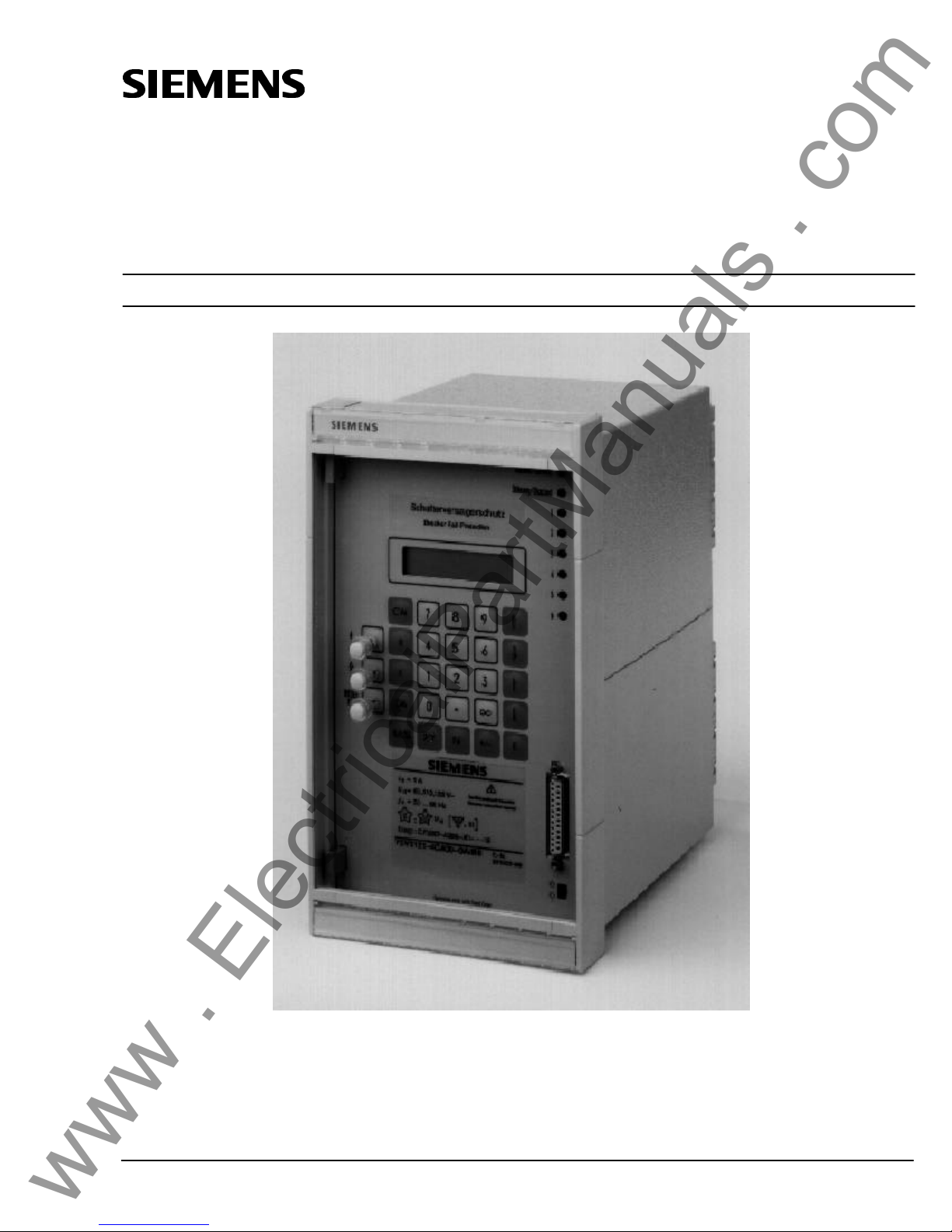
Figure 1 Illustration of the numerical circuit breaker failure protection relay 7SV512 (in flush mounting case)
E Siemens AG 1994

www . ElectricalPartManuals . com

Conformity7SV512 V1
iiiC53000---G1176---C91
Conformity
This product is inconformity with thedirective of the Council ofthe European Communities on the approximation of the laws of the Member States relating to electromagnetic compatibility (EMC Council Directive
89/336/EEC) and concerning electrical equipment for application within specified voltage limits (Low-voltage
directive 73/23 EEC).
Conformity isproved bytests that had been performedaccording to article10 oftheCouncil Directive inaccordance with the generic standards EN 50081---2 and EN 50082---2 (for EMC directive) and the standards EN
60255---6 (for low-voltage directive) by Siemens AG by Siemens AG.
The device is designed and manufactured for application in industrial environment.
The device is designed in accordance with the international standards of IEC 60255 and the German stan-
dards DIN 57435 part 303 (corresponding to VDE 0435 part 303).
www . ElectricalPartManuals . com

Conformity7SV512 V1
C53000---G1176---C91
iv
This page intentionally left blank.
www . ElectricalPartManuals . com

7SV512 ContentsV1
vC53000---G1176---C91
Contents
1 Introduction 9. .. . .. . . .. . .. . . .. . .. . . .. . .. . . .. . .. . .. . . .. . .. . . .. . .. . . .. . .. . . .. . .. . .. . . .
1.1 Application 9. .. . .. . . .. . .. . . .. . .. . . .. . .. . . .. . .. . .. . . .. . .. . . .. . .. . . .. . .. . . .. . .. . .. . . .. . .
1.2 Features 10. .. . .. . . .. . .. . . .. . .. . . .. . .. . . .. . .. . .. . . .. . .. . . .. . .. . . .. . .. . . .. . .. . .. . . .. . ..
2 Design 11. .. . .. . . .. . .. . . .. . .. . . .. . .. . . .. . .. . .. . . .. . .. . . .. . .. . . .. . .. . . .. . .. . .. . . .. . .. .
2.1 Arrangements 11. .. . .. . . .. . .. . .. . . .. . .. . . .. . .. . . .. . .. . . .. . .. . .. . . .. . .. . . .. . .. . . .. . .. . .
2.2 Dimensions 13. .. . .. . . .. . .. . . .. . .. . . .. . .. . . .. . .. . .. . . .. . .. . . .. . .. . . .. . .. . . .. . .. . .. . . ..
2.3 Ordering data 15. .. . .. . . .. . .. . .. . . .. . .. . . .. . .. . . .. . .. . . .. . .. . .. . . .. . .. . . .. . .. . . .. . .. . .
3 Technical Data 16. .. . .. . . .. . .. . . .. . .. . . .. . .. . . .. . .. . .. . . .. . .. . . .. . .. . . .. . .. . . .. . .. . .
3.1 General data 16. .. . .. . . .. . .. . . .. . .. . . .. . .. . . .. . .. . .. . . .. . .. . . .. . .. . . .. . .. . . .. . .. . .. . . .
3.1.1 Inputs/outputs 16. . .. . . .. . .. . . .. . .. . . .. . .. . .. . . .. . .. . . .. . .. . . .. . .. . . .. . .. . .. . . .. . .. . . .. .
3.1.2 Electrical tests 18.. . .. . .. . . .. . .. . . .. . .. . . .. . .. . .. . . .. . .. . . .. . .. . . .. . .. . . .. . .. . .. . . .. . .. .
3.1.3 Mechanical stress tests 19. .. . .. . . .. . .. . . .. . .. . . .. . .. . . .. . .. . .. . . .. . .. . . .. . .. . . .. . .. . . .. .
3.1.4 Climatic stress tests 20. .. . .. . . .. . .. . . .. . .. . . .. . .. . . .. . .. . .. . . .. . .. . . .. . .. . . .. . .. . . .. . .. .
3.1.5 Service conditions 20.. . . .. . .. . . .. . .. . . .. . .. . .. . . .. . .. . . .. . .. . . .. . .. . . .. . .. . .. . . .. . .. . . .
3.1.6 Design 20. .. . .. . . .. . .. . . .. . .. . . .. . .. . . .. . .. . .. . . .. . .. . . .. . .. . . .. . .. . . .. . .. . .. . . .. . .. . .
3.2 Circuit breaker failure protection 21. .. . .. . . .. . .. . . .. . .. . . .. . .. . . .. . .. . .. . . .. . .. . . .. . .. . .
3.3 Circuit breaker pole discrepancy supervision 21. .. . .. . . .. . .. . . .. . .. . . .. . .. . . .. . .. . .. . . ..
3.4 Ancillary functions 22. . . .. . .. . .. . . .. . .. . . .. . .. . . .. . .. . . .. . .. . .. . . .. . .. . . .. . .. . . .. . .. . . .
4 Method of operation 23. .. . .. . . .. . .. . . .. . .. . . .. . .. . . .. . .. . .. . . .. . .. . . .. . .. . . .. . .. . . .
4.1 Operation of complete unit 23. .. . .. . . .. . .. . . .. . .. . . .. . .. . . .. . .. . .. . . .. . .. . . .. . .. . . .. . ..
4.2 Circuit breaker failure protection 25. .. . .. . . .. . .. . . .. . .. . . .. . .. . . .. . .. . .. . . .. . .. . . .. . .. . .
4.2.1 General 25. .. . .. . . .. . .. . . .. . .. . . .. . .. . . .. . .. . .. . . .. . .. . . .. . .. . . .. . .. . . .. . .. . .. . . .. . .. . .
4.2.2 Current flow monitoring 26. .. . .. . .. . . .. . .. . . .. . .. . . .. . .. . . .. . .. . .. . . .. . .. . . .. . .. . . .. . .. . .
4.2.3 Processing of the circuit breaker auxiliary contacts 27. .. . .. . . .. . .. . . .. . .. . . .. . .. . . .. . .. . .. . .
4.2.4 Initiation conditions and delay times 29. .. . .. . . .. . .. . . .. . .. . . .. . .. . . .. . .. . .. . . .. . .. . . .. . .. .
4.2.4.1 Common phase initiation 29.. . . .. . .. . . .. . .. . . .. . .. . .. . . .. . .. . . .. . .. . . .. . .. . . .. . .. . .. . . ..
4.2.4.2 Two-stage breaker failure protection with common phase initiation 30. .. . .. . . .. . .. . . .. . .. . . .. .
4.2.4.3 Phase segregated initiation 30. .. . .. . . .. . .. . . .. . .. . . .. . .. . . .. . .. . .. . . .. . .. . . .. . .. . . .. . .. .
4.2.4.4 Combined initiation conditions 33. .. . .. . . .. . .. . . .. . .. . . .. . .. . . .. . .. . .. . . .. . .. . . .. . .. . . .. .
4.2.4.5 Function examples 33.. . .. . . .. . .. . .. . . .. . .. . . .. . .. . . .. . .. . . .. . .. . .. . . .. . .. . . .. . .. . . .. . ..
4.2.5 Circuit breaker not fully operational 34. .. . .. . . .. . .. . . .. . .. . . .. . .. . . .. . .. . .. . . .. . .. . . .. . .. .
4.2.6 Transfer trip to the remote end circuit breaker 34. .. . .. . . .. . .. . . .. . .. . . .. . .. . . .. . .. . .. . . .. . .
4.2.7 Hardware supervision and blocking 34. .. . .. . . .. . .. . . .. . .. . . .. . .. . . .. . .. . .. . . .. . .. . . .. . .. .
4.3 End fault protection 36. .. . .. . . .. . .. . . .. . .. . . .. . .. . . .. . .. . .. . . .. . .. . . .. . .. . . .. . .. . . .. . ..
4.4 Circuit breaker pole discrepancy supervision 36. .. . .. . . .. . .. . . .. . .. . . .. . .. . . .. . .. . .. . . ..
4.5 Ancillary functions 37. . . .. . .. . .. . . .. . .. . . .. . .. . . .. . .. . . .. . .. . .. . . .. . .. . . .. . .. . . .. . .. . . .
4.5.1 Processing of annunciations 37. .. . .. . . .. . .. . . .. . .. . . .. . .. . . .. . .. . .. . . .. . .. . . .. . .. . . .. . ..
4.5.1.1 Indicators and binary outputs (signal relays) 37. .. . .. . . .. . .. . . .. . .. . . .. . .. . . .. . .. . .. . . .. . ..
4.5.1.2 Information on the display panel or to a personal computer 37. .. . .. . . .. . .. . . .. . .. . . .. . .. . . ..
4.5.1.3 Information to a central unit (optional) 38. .. . .. . . .. . .. . . .. . .. . . .. . .. . . .. . .. . .. . . .. . .. . . .. . .
4.5.2 Data storage and transmission for fault recording 38. .. . .. . . .. . .. . . .. . .. . . .. . .. . . .. . .. . .. . . .
4.5.3 Operating measurements and conversion 38. .. . .. . . .. . .. . . .. . .. . . .. . .. . . .. . .. . .. . . .. . .. . .
www . ElectricalPartManuals . com

Contents7SV512 V1
C53000---G1176---C91
vi
4.5.4 Monitoring functions 39. .. . .. . . .. . .. . . .. . .. . . .. . .. . . .. . .. . .. . . .. . .. . . .. . .. . . .. . .. . . .. . ..
4.5.4.1 Hardware monitoring 39. .. . .. . . .. . .. . . .. . .. . . .. . .. . . .. . .. . .. . . .. . .. . . .. . .. . . .. . .. . . .. . ..
4.5.4.2 Software monitoring 40. . .. . .. . . .. . .. . . .. . .. . .. . . .. . .. . . .. . .. . . .. . .. . . .. . .. . .. . . .. . .. . . ..
4.5.4.3 Monitoring of external measuring transformer circuits 40. .. . .. . . .. . .. . . .. . .. . . .. . .. . . .. . .. . .
5 Installation instructions 41. .. . .. . . .. . .. . . .. . .. . . .. . .. . . .. . .. . .. . . .. . .. . . .. . .. . . .. . .
5.1 Unpacking and repacking 41.. . .. . . .. . .. . . .. . .. . . .. . .. . .. . . .. . .. . . .. . .. . . .. . .. . . .. . .. . .
5.2 Preparations 41. . . .. . .. . .. . . .. . .. . . .. . .. . . .. . .. . . .. . .. . .. . . .. . .. . . .. . .. . . .. . .. . . .. . .. .
5.2.1 Mounting and connections 42. .. . .. . . .. . .. . . .. . .. . . .. . .. . . .. . .. . .. . . .. . .. . . .. . .. . . .. . .. . .
5.2.1.1 Model 7SV512K---KBKKK for panel surface mounting 42. .. . .. . . .. . .. . . .. . .. . . .. . .. . . .. . .. . ..
5.2.1.2 Model 7SV512K---KCKKK for panel flush mounting or cubicle installation 42. .. . .. . . .. . .. . . .. . ..
5.2.2 Checking the rated data 42. .. . .. . . .. . .. . . .. . .. . . .. . .. . . .. . .. . .. . . .. . .. . . .. . .. . . .. . .. . . ..
5.2.2.1 Control d.c. voltage of binary inputs 42. . .. . . .. . .. . . .. . .. . . .. . .. . .. . . .. . .. . . .. . .. . . .. . .. . . .
5.2.3 Checking the LSA data transmission link 44. .. . .. . . .. . .. . . .. . .. . . .. . .. . . .. . .. . .. . . .. . .. . . .
5.2.4 Connections 45. .. . .. . . .. . .. . .. . . .. . .. . . .. . .. . . .. . .. . . .. . .. . .. . . .. . .. . . .. . .. . . .. . .. . . ..
5.2.5 Checking the connections 47. .. . .. . . .. . .. . . .. . .. . . .. . .. . . .. . .. . .. . . .. . .. . . .. . .. . . .. . .. . .
5.3 Configuration of operational functions 48. .. . . .. . .. . . .. . .. . . .. . .. . . .. . .. . .. . . .. . .. . . .. . .
5.3.1 Operational preconditions 48. . .. . .. . .. . . .. . .. . . .. . .. . . .. . .. . . .. . .. . .. . . .. . .. . . .. . .. . . .. .
5.3.2 Settings for operating parameters --- address block 70 48. .. . .. . . .. . .. . . .. . .. . . .. . .. . . .. . .. .
5.4 Configuration of the device functions 51. .. . .. . . .. . .. . . .. . .. . . .. . .. . . .. . .. . .. . . .. . .. . . ..
5.4.1 Introduction 51. .. . .. . . .. . .. . . .. . .. . . .. . .. . . .. . .. . .. . . .. . .. . . .. . .. . . .. . .. . . .. . .. . .. . . .. .
5.4.2 Programming the scope of functions --- address block 78 52. .. . .. . . .. . .. . . .. . .. . . .. . .. . . .. . .
5.5 Marshalling of binary inputs, binary outputs and LED indicators 53. .. . .. . . .. . .. . . .. . .. . . .
5.5.1 Introduction 53. .. . .. . . .. . .. . . .. . .. . . .. . .. . . .. . .. . .. . . .. . .. . . .. . .. . . .. . .. . . .. . .. . .. . . .. .
5.5.2 Marshalling of the binary inputs --- address block 61 55. .. . .. . . .. . .. . . .. . .. . . .. . .. . . .. . .. . ..
5.5.3 Marshalling of the signal output relays --- address block 62 58. . .. . .. . . .. . .. . . .. . .. . . .. . .. . . .
5.5.4 Marshalling of the LED indicators --- address block 63 61. .. . .. . . .. . .. . . .. . .. . . .. . .. . . .. . .. . .
5.5.5 Marshalling of the command (trip) relays --- address block 64 63. .. . .. . . .. . .. . . .. . .. . . .. . .. . .
5.6 Configuration parameters for localized substation automation --- address block 69 65. .. . ..
6 Operating instructions 67. . .. . .. . . .. . .. . .. . . .. . .. . . .. . .. . . .. . .. . . .. . .. . .. . . .. . .. . . .
6.1 Safety precautions 67. . .. . . .. . .. . . .. . .. . .. . . .. . .. . . .. . .. . . .. . .. . . .. . .. . .. . . .. . .. . . .. . ..
6.2 Dialog with the relay 67. .. . .. . . .. . .. . . .. . .. . . .. . .. . . .. . .. . .. . . .. . .. . . .. . .. . . .. . .. . . .. . .
6.2.1 Membrane keyboard and display panel 67.. . .. . .. . . .. . .. . . .. . .. . . .. . .. . . . . . .. . .. . . .. . .. . .
6.2.2 Operation with a personal computer 68. .. . .. . . .. . .. . . .. . .. . . .. . .. . . .. . .. . .. . . .. . .. . . .. . ..
6.2.3 Operational preconditions 68. . .. . .. . .. . . .. . .. . . .. . .. . . .. . .. . . .. . .. . .. . . .. . .. . . .. . .. . . .. .
6.2.4 Representation of the relay (front view) 69. .. . .. . . .. . .. . . .. . .. . . .. . .. . . .. . .. . .. . . .. . .. . . .. .
6.3 Setting the functional parameters 70. .. . .. . . .. . .. . . .. . .. . . .. . .. . . .. . .. . .. . . .. . .. . . .. . .. .
6.3.1 Introduction 70. .. . .. . . .. . .. . . .. . .. . . .. . .. . . .. . .. . .. . . .. . .. . . .. . .. . . .. . .. . . .. . .. . .. . . .. .
6.3.1.1 Parameterizing procedure 70. .. . . .. . .. . . .. . .. . .. . . .. . .. . . .. . .. . . .. . .. . . .. . .. . .. . . .. . .. . .
6.3.1.2 Selectable parameter sets 71. . .. . .. . . .. . .. . .. . . .. . .. . . .. . .. . . .. . .. . . .. . .. . .. . . .. . .. . . .. .
6.3.1.3 Setting of date and time 72. .. . . .. . .. . . .. . .. . . .. . .. . . .. . .. . .. . . .. . .. . . .. . .. . . .. . .. . . .. . ..
6.3.2 Initial displays --- address blocks 00 and 10 73. .. . .. . . .. . .. . . .. . .. . . .. . .. . . .. . .. . .. . . .. . .. .
6.3.3 Power system data --- address block 11 73. .. . .. . . .. . .. . . .. . .. . . .. . .. . . .. . .. . .. . . .. . .. . . ..
6.3.4 Settings for circuit breaker failure protection --- address block 12 75. .. . .. . . .. . .. . . .. . .. . . .. . .
6.3.5 Settings for fault recording --- address block 28 80. .. . .. . . .. . .. . . .. . .. . . .. . .. . . .. . .. . .. . . .. .
6.3.6 Settings for measured value monitoring --- address block 29 81. .. . .. . . .. . .. . . .. . .. . . .. . .. . . .
6.3.7 Settings for breaker pole discrepancy supervision --- address block 38 82. .. . .. . . .. . .. . . .. . .. .
6.4 Annunciations 83. .. . .. . . .. . .. . .. . . .. . .. . . .. . .. . . .. . .. . . .. . .. . .. . . .. . .. . . .. . .. . . .. . .. . .
6.4.1 Introduction 83. .. . .. . . .. . .. . . .. . .. . . .. . .. . . .. . .. . .. . . .. . .. . . .. . .. . . .. . .. . . .. . .. . .. . . .. .
6.4.2 Operational annunciations --- address block 51 84. .. . .. . . .. . .. . . .. . .. . . .. . .. . . .. . .. . .. . . .. .
6.4.3 Fault annunciations --- address block 52 to 54 88. .. . .. . . .. . .. . . .. . .. . . .. . .. . . .. . .. . .. . . .. . .
6.4.4 Circuit breaker operation statistics --- address block 56 91. .. . .. . . .. . .. . . .. . .. . . .. . .. . . .. . .. .
6.4.5 Read-out of operational measured values --- address block 57 92. .. . .. . . .. . .. . . .. . .. . . .. . .. .
www . ElectricalPartManuals . com

7SV512 ContentsV1
viiC53000---G1176---C91
6.5 Operational control facilities 93.. . .. . . .. . .. . .. . . .. . .. . . .. . .. . . .. . .. . . .. . .. . .. . . .. . .. . . ..
6.5.1 Adjusting and synchronizing the real time clock --- address block 81 93. .. . .. . . .. . .. . . .. . .. . . .
6.5.2 Erasing stored annunciations and counters --- address block 82 94. .. . .. . . .. . .. . . .. . .. . . .. . ..
6.5.3 Off/On control of part functions of the device 95. .. . .. . . .. . .. . . .. . .. . . .. . .. . . .. . .. . .. . . .. . ..
6.5.4 Selection of parameter sets --- address block 85 97. .. . .. . . .. . .. . . .. . .. . . .. . .. . . .. . .. . .. . . ..
6.5.4.1 Read-out of settings of a parameter set 97. . .. . . .. . .. . . .. . .. . . .. . .. . .. . . .. . .. . . .. . .. . . .. . ..
6.5.4.2 Change-over of the active parameter set from the operating panel 97. . . .. . .. . . .. . .. . . .. . .. . . .
6.5.4.3 Change-over of the active parameter set via binary inputs 98. .. . .. . . .. . .. . . .. . .. . . .. . .. . . .. .
6.6 Testing and commissioning 99. .. . .. . . .. . .. . . .. . .. . . .. . .. . . .. . .. . .. . . .. . .. . . .. . .. . . .. . ..
6.6.1 General 99. .. . .. . . .. . .. . . .. . .. . . .. . .. . . .. . .. . .. . . .. . .. . . .. . .. . . .. . .. . . .. . .. . .. . . .. . .. . .
6.6.2 Testing the circuit breaker failure protection 100.. . . .. . .. . . .. . .. . . .. . .. . . .. . .. . .. . . .. . .. . . ..
6.6.3 Testing the end fault protection 101. .. . .. . . .. . .. . . .. . .. . . .. . .. . . .. . .. . .. . . .. . .. . . .. . .. . . ..
6.6.4 Testing the circuit breaker pole discrepancy supervision 101. .. . .. . . .. . .. . . .. . .. . . .. . .. . . .. . .
6.7 Commissioning using primary tests 102. .. . .. . . .. . .. . . .. . .. . . .. . .. . . .. . .. . .. . . .. . .. . . .. .
6.7.1 Checking the initiation conditions 102. .. . .. . . .. . .. . . .. . .. . . .. . .. . . .. . .. . .. . . .. . .. . . .. . .. . .
6.7.2 Checking the local trip with breaker failure criterion from the auxiliary contacts 103. .. . .. . . .. . ..
6.7.3 Checking the local trip and the current circuits 103. .. . .. . . .. . .. . . .. . .. . . .. . .. . . .. . .. . .. . . ..
6.7.4 Checking the intertrip to the opposite feeder end 104. .. . .. . . .. . .. . . .. . .. . . .. . .. . . .. . .. . .. . .
6.7.4 Checking the bus-bar trip 104.. . .. . .. . .. . . .. . .. . . .. . .. . . .. . .. . . .. . .. . .. . . .. . .. . . .. . .. . . ..
6.8 Putting the relay into operation 105. .. . .. . . .. . .. . . .. . .. . . .. . .. . . .. . .. . .. . . .. . .. . . .. . .. . .
7 Maintenance and fault tracing 106. . . .. . .. . . .. . .. . .. . . .. . .. . . .. . .. . . .. . .. . . .. . .. . .
7.1 Routine checks 106. .. . .. . . .. . .. . . .. . .. . . .. . .. . . .. . .. . .. . . .. . .. . . .. . .. . . .. . .. . . .. . .. . ..
7.2 Replacing the clock module 107. .. . .. . . .. . .. . . .. . .. . . .. . .. . . .. . .. . .. . . .. . .. . . .. . .. . . .. .
7.3 Fault tracing 108.. . .. . . .. . .. . .. . . .. . .. . . .. . .. . . .. . .. . . .. . .. . .. . . .. . .. . . .. . .. . . .. . .. . . ..
7.3.1 Replacing the mini-fuse 109. .. . .. . . .. . .. . . .. . .. . . .. . .. . . .. . .. . .. . . .. . .. . . .. . .. . . .. . .. . . ..
8 Repairs 111. . .. . .. . . .. . .. . . .. . .. . . .. . .. . . .. . .. . .. . . .. . .. . . .. . .. . . .. . .. . . .. . .. . .. . . ..
9 Storage 111. . .. . .. . . .. . .. . . .. . .. . . .. . .. . . .. . .. . .. . . .. . .. . . .. . .. . . .. . .. . . .. . .. . .. . . ..
Appendix 112. .. . . .. . .. . . .. . .. . . .. . .. . .. . . .. . .. . . .. . .. . . .. . .. . . .. . .. . .. . . .. . .. . . .. . .. . .
A General diagrams 113.. . . .. . .. . . .. . .. . . .. . .. . .. . . .. . .. . . .. . .. . . .. . .. . . .. . .. . .. . . .. . .. . .
B Connection diagrams 116. .. . .. . . .. . .. . . .. . .. . . .. . .. . . .. . .. . .. . . .. . .. . . .. . .. . . .. . .. . . ..
C Tables 119. .. . . .. . .. . . .. . .. . . .. . .. . .. . . .. . .. . . .. . .. . . .. . .. . . .. . .. . .. . . .. . .. . . .. . .. . . .
NOTE:
This instruction manual does not purport tocover all
details in equipment, nor to provide for every possible contingency to be met in connection with installation, operation or maintenance.
Should further information bedesired or should particular problems arise which are not covered sufficiently for the purchaser’s purpose, the matter
should be referred to the local Siemens sales office.
The contents of this instruction manual shall not become part nor modify any prior or existing agreement, commitment or relationship. The sales contract contains the entire obligations ofSiemens. The
warranty contained in the contract between the parties is thesole warranty of Siemens. Any statements
contained herein do not create new warranties nor
modify the existing warranty.
www . ElectricalPartManuals . com

Contents7SV512 V1
C53000---G1176---C91
viii
This page intentionally left blank.
www . ElectricalPartManuals . com

Introduction7SV512V1
9C53000---G1176---C91
1 Introduction
1.1 Application
The numerical circuitbreaker failure protection relay
7SV512 provides rapid back-up fault clearance instruction to the associated circuit breakers in case
the circuit breaker nearest to the fault fails to respond.
It issuitable for powersystems ofall voltage ranges.
The initiation signal can be derived from anyprotection or supervision equipment or, in case of manual
opening, from the discrepancy control switch of the
breaker. Information from the circuit breaker auxiliary contact(s) is required for the breaker failure protection to function during faults which produce little
or no current flow (e.g. Buchholz protection).
The breaker failure protection can operate singlestage or two-stage. When used as single-stage protection, the bus trip command is given to the adjacent circuit breakers if the protected feeder breaker
fails. When used as two-stage protection, the first
stage canbe used torepeat the tripcommand to the
relevant breaker,normallyon different tripcoils,if the
initial tripcommand from thefeeder protection is not
executed. Thesecond stage willresult inabus trip to
the adjacent breakers, if the command of the first
stage is not successful.
The bus trip command from the breaker failure protection can be routed to all circuit breakers linked to
the same bus-bar (section) as the breaker that
failed. It can also be transmitted to the remote end
by means of a suitable communication link (e.g.
PLC, radio wave, or optical fibre). The distribution
logic which is necessary in case of multiple bus-bar
sections is not part of 7SV512 relay.
The current level is monitored in each of the three
phases against a set threshold. In addition, the residual earth current is monitored or --- if this is not
available --- the negative sequence component of
the phase currents derived by symmetrical component analysis. This ensures high security against
malfunction by use of a 2-out-of-4 check of the current detectors.
Phase segregated current monitoring enables reliable breaker failure detection even during singlepole auto-reclose cycles provided the phase segregated trip signals of the feeder protection are connected to 7SV512. If two-stage breaker failure protection is used in conjunction with single-pole tripping bythe feeder protection, the firststage trip may
be performed single-pole or three-pole, as selected
by the user. Different delay times can be set for
single-phase faults and multi-phase faults.
If the protected circuit breaker is not operative (e.g.
air pressure failure), instantaneous bus trip of the
adjacent circuit breakers can be achieved following
a feeder protection trip provided the relay is informed by an external breaker monitor.
An end fault protection function is integrated in the
7SV512 relay. An end fault is a short-circuit located
between the circuit breaker and the current transformer set of the feeder. For this fault current flow is
detected although the auxiliary contacts of the
breaker indicate open breaker pole(s). A command
signal is generated which can be transmitted to the
remote end breaker.
A circuit breaker pole discrepancy supervision is integrated in the 7SV512. It prevents that only one or
two poles of the breaker are open continuously. A
three-pole trip is initiated when pole discrepancy is
detected for a set time.
Special measures are taken to prevent malfunction
ofthe relay.Besides the mentioned 2-out-of-4 check
of the current detection elements the trip signals of
the feeder protection must be connected in redundant manner so that theycan be checked forplausibility. An additional hard-ware monitor ensures multi-channel controlof thetrip relays.Continuous monitoring ofthe measured values permits rapid annunciation of any fault in the measuring transformer circuits. Continuous plausibility monitoring of theinter nal measured value processing circuits and monitoring ofthe auxiliary voltages toensure that they remain within tolerance are obviously inherent features.
Throughout a fault in the network the magnitudes of
the instantaneous values are stored for a period of
max. 3 seconds (0.66 seconds at 50 Hz for transmission to acentral computer station) and are available for subsequent fault analysis.
Serial interfaces allow comprehensive communication with other digital control and storage devices.
Fordata transmission a standardized protocol in accordance with DIN 19244 is used. The device can
therefore be incorporated in Localized Substation
Automation networks (LSA).
www . ElectricalPartManuals . com

Introduction7SV512V1
C53000---G1176---C91
10
1.2 Features
--- Processor system with powerful 16---bit---microprocessor;
--- Complete digital measured value processing and
control from data acquisition and digitizing of the
measured values up to the trip decisions for the
circuit breakers;
--- Complete galvanic and reliable separation of the
internal processing circuits from the measurement, control and supply circuits of the system,
with screened analog input transducers, binary
input and output modules and DC converter;
--- Highly sensitive current detection;
--- Independent current detectors for monitoring of
current flowthrough each individual circuit breaker pole;
--- 2-out-of-4 check of the current detectors;
--- Short reset time, negligible overshoot time;
--- Independent delay times for each circuit breaker
pole;
--- Single-stage or two-stage delay;
--- Can be controlled from circuit breaker auxiliary
contacts; ifsingle-pole control isused, theindividual auxiliary contacts of each pole, or series and
parallel connection of the auxiliary contacts can
be connected;
--- Can be initiated by single-pole or three-pole trip
commands;
--- Can be initiated by different protection relays,
even single-pole or three-pole or both;
--- Instantaneous trip possible in case of defective
circuit breaker;
--- Transmission of trip command to the remote end
possible;
--- Integrated end fault protection for intertrip;
--- Integrated circuit breaker pole discrepancy supervision;
--- Calculation of operational measured values and
indication on the front display;
--- Simple setting and operation using theintegrated
operation panelor aconnected personal computer with menu-guided software;
--- Communication with central control and storage
devices via serial interfaces is possible by means
of optical fibre;
--- Annunciation storage of the last three network
faults, with optional real time clock;
--- Data storage and transmission for fault records
giving
rapid fault analysis,
detailed fault records;
--- Counting of trippingcommands aswell asrecording of fault data and accumulative addition of the
interrupted fault currents;
--- Continuous self-monitoring right from the d.c. circuits, throughthe currentand voltage transformer
inputs to the tripping relays, thus achieving maximum availability and a more corrective than preventive maintenance strategy.
www . ElectricalPartManuals . com

Design
7SV512 V1
11
C53000--G1176--C91
2 Design
2.1 Arrangements
All protection functions including dc/dc converter are
accommodated on one Double Europa Format plugin module. This module is installed in a 7XP20 housing. Two different types of housing can be delivered:
-- 7SV512K--KBKKK-- in housing 7XP2030--1 for
panel surface mounting
The housing hasfull sheet-metal covers,as well as
a removable front cover with transparent plastic
window.
Guide rails are built in for the support of plug-in
modules. On the top and bottom plates of the
housing, contact areas which are electrically connected to the housing are installed to mate withthe
earthing springs of the module. Connection to
earth is made before the plugs make contact.
Earthing screws have been provided on the left
hand side of the housing. Additionally, terminal 16
is connected to the case.
All external signals are connected by means of 60
screwed terminals which are arranged over cutouts on the top and bottom covers. The terminals
are numbered consecutively from left to right at the
bottom and top.
The heavy duty current plug connectors provide
automatic shorting of the c.t. circuits whenever the
module is withdrawn. This does not release from
the care to be taken when c.t. secondary circuits
are concerned.
For the optional interface to a central control and
storage unit, an additional coupling facility has
been provided. Forthe optical fibre interface (mod-
el 7SV512K--KKKKK--KC), two F--SMA connectors
are provided.
The degree of protection for the housing is IP51,
for the terminals IP21. For dimensions please refer
to Figure 2.2.
-- 7SV512K--KCKKK-- in housing 7XP2030--2 for
panel flush mounting or cubicle installation
The housing hasfull sheet-metal covers,as well as
a removable front cover with transparent plastic
window.
Guide rails are built in for the support of plug-in
modules. On the top and bottom plates of the
housing, contact areas which are electrically connected to the housing are installed to mate withthe
earthing springs of the module. Connection to
earth is made before the plugs make contact.
Earthing screws have been provided on the rear
wall of the housing.
All external signals are connected by means of
connector modules which are mounted on the rear
cover over cut-outs. For each electrical connection, one screwed terminal and one parallel snapin terminal are provided. For field wiring, the use of
the screwed terminals is recommended; snap-in
connection requires special tools.
The heavy duty current plug connectors provide
automatic shorting of the c.t. circuits whenever the
module is withdrawn. This does not release from
the care to be taken when c.t. secondary circuits
are concerned.
For the optional interface to optical fibres
(7SV512K--KKKKK--KC), a module with 2 F--SMA
connectors is provided.
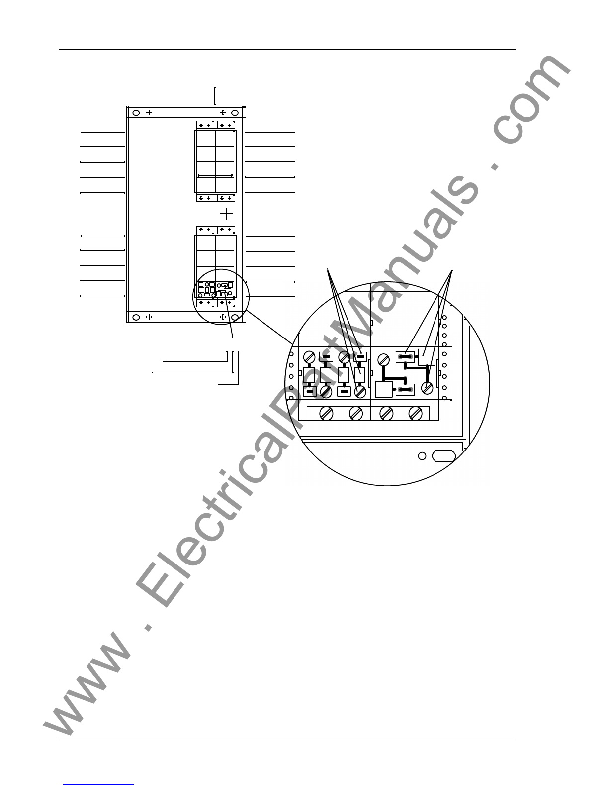
The plug modules are labelled according to their
mounting position by means of a grid system (e.g.
1A2). The individual connections within a module
are numbered consecutively from left to right
(when viewed from the rear), (e.g. 1A2); refer to
Figure 2.1.
Degree of protection for the housing is IP51, forthe
terminals IP21. For dimensions please refer to Figure 2.3.
www . ElectricalPartManuals . com
Design
7SV512 V1
C53000--G1176--C9112
Heavy current connector
e.g. 1A2
Voltage connector
e.g. 1B4
1A2
1
2
2
1
42
3
1
2
3
4
5
6
7
8
B A
B A
8
7
6
5
4
3
2
1
8
7
6
5
4
3
2
1
1
horizontal position
vertical position
consecutive connection number
Figure 2.1 Connection plugs (rear view) -- housing for flush mounting -- example
www . ElectricalPartManuals . com
Design
7SV512 V1
13
C53000--G1176--C91
2.2 Dimensions
Figures 2.2 and 2.3 show the dimensions of the various types of housing available.
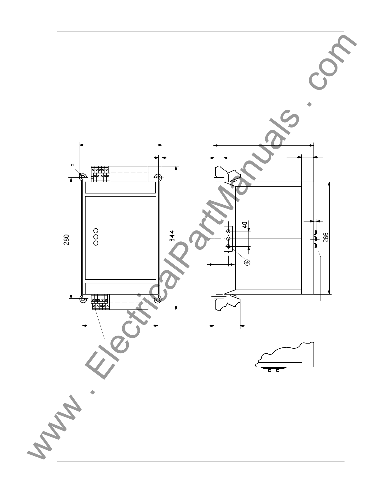
7SV512 Housing for panel surface mounting 7XP2030--1
Max. 60 terminals for cross-section max. 7 mm
2
9
71
260
27
29.5
1.5
Interface for optical
fibre below
Reset and
paging buttons
39
15
159
144
7.5
46 60
1
16
4531
Earthing terminal 16
30
....
....
....
....
Optical fibre connectors:
integrated F--SMA connector
e.g for glass fibre 62.5/125/um
Dimensions in mm
Figure 2.2 Dimensions for housing 7XP2030--1 for panel surface mounting
www . ElectricalPartManuals . com
Design
7SV512 V1
C53000--G1176--C9114
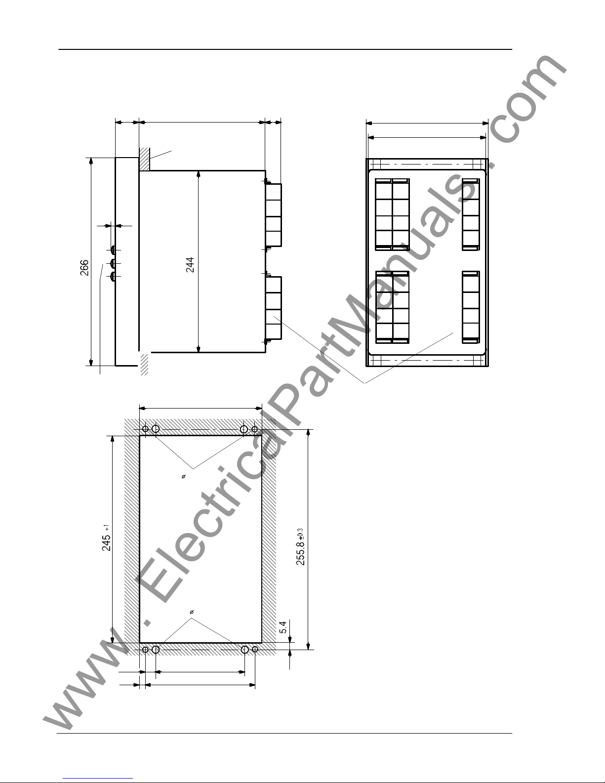
7SV512 Housing for panel flush mounting or cubicle installation 7XP2030--2
Mounting plate
Connector modules
Reset and paging
buttons
Panel cut-out
29.5
146
105
131.5
13.2
7.3
+2
+0.5
+0.3
--
--
5 or M4
6
172 30
1.5
Dimensions in mm
Heavy current connectors:
Screwed terminal for max. 4 mm2.
Twin spring crimp connector in parallel for
max. 2.5 mm2.
Further connectors:
Screwed terminal for max. 1.5 mm2.
Twin spring crimp connector in parallel for
max. 1.5 mm2.
Optical fibre connectors:
integrated F--SMA connector,
with ceramic post,
e.g for glass fibre 62.5/125/um
8
7
6
5
4
3
2
1
145
D C A
150
8
7
6
5
4
3
2
1
Figure 2.3 Dimensions for housing 7XP2030--2 for panel flush mounting or cubicle installation
www . ElectricalPartManuals . com
Design
7SV512 V1
15
C53000--G1176--C91
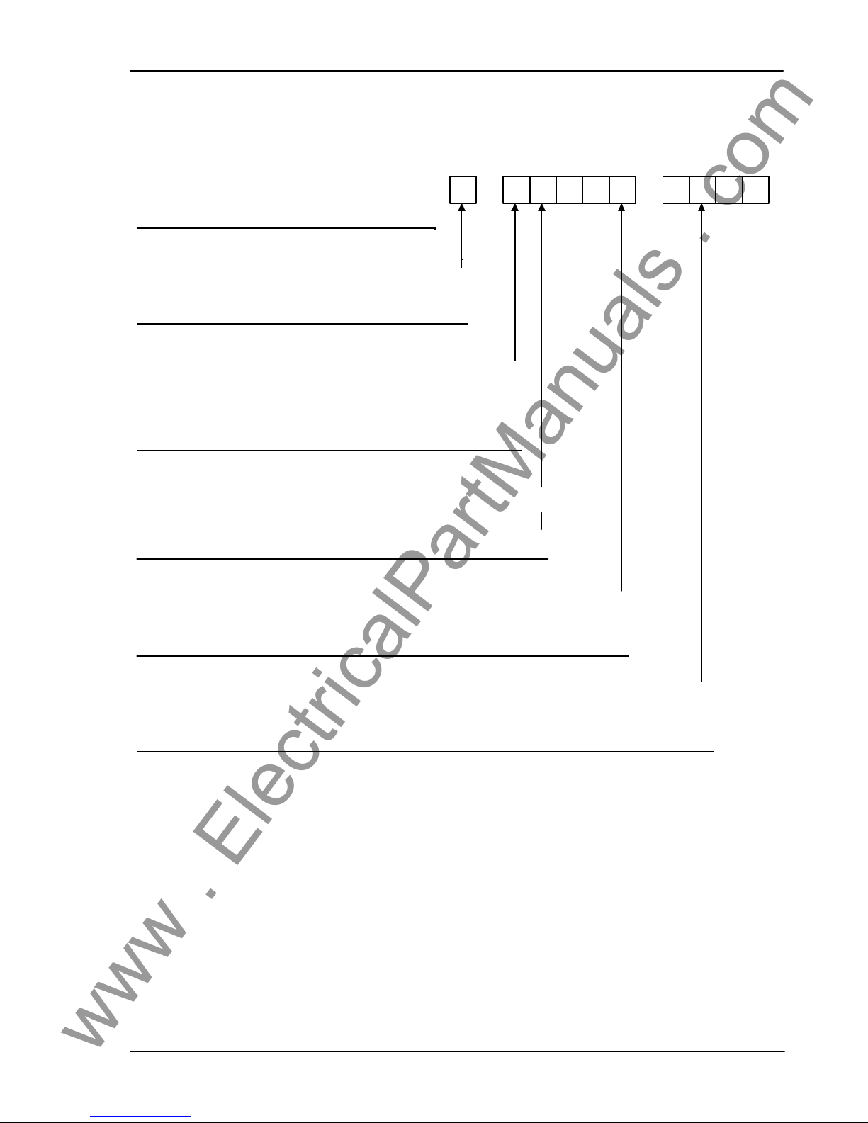
2.3 Ordering data
Auxiliary voltage
24/48 V dc 2. . . . . . . . . . . . . . . . . . . . . . . . . . . . . . . . . . . . . . . . . . . .
60/110/125 V dc 4. . . . . . . . . . . . . . . . . . . . . . . . . . . . . . . . . . . . . . . .
220/250 V dc 5. . . . . . . . . . . . . . . . . . . . . . . . . . . . . . . . . . . . . . . . . .
Rated current; rated frequency
1 A; 50/60 Hz 1. . . . . . . . . . . . . . . . . . . . . . . . . . . . . . . . . . .
5 A; 50/60 Hz 5. . . . . . . . . . . . . . . . . . . . . . . . . . . . . . . . . . .
7. 8. 9. 10. 11. 12. 13. 14.
A 0
Numerical Circuit Breaker
Failure Protection 7 S V 5 1 2
Construction
in housing 7XP2030 for panel surface mounting B. . . . . . . . . . . . . . . .
in housing 7XP2030 for panel flush mounting or
cubicle installation C. . . . . . . . . . . . . . . . . . . . . . . . . . . . . . . . . . . . . . . . . .
Serial interface for coupling to a control centre
without serial interface A. . . . . . . . . . . . . . . . . . . . . . . . . . . . . . . . . . . . . . . . . . . . . . . . . . . . . . . . . . . . . .
with serial interface for optical fibre connection C. . . . . . . . . . . . . . . . . . . . . . . . . . . . . . . . . . . . . . . . .
0
Supplementary annunciation functions
without 0. . . . . . . . . . . . . . . . . . . . . . . . . . . . . . . . . . . . . . . . . . . . . . . . . . . . . . . . . . . . . . . .
with real time clock and non-volatile annunciation memories 1. . . . . . . . . . . . . . . . . .
--- ---
15. 16.
A 0
www . ElectricalPartManuals . com

Technical data7SV512
V1
C53000---G1176---C9116
3 Technical data
3.1 General data
3.1.1 Inputs/outputs
Measuring circuits
Rated current I
N
1 A or 5 A
Rated frequency f
N
50 Hz/60 Hz (settable)
Power consumption current path at IN= 1 A approx 0.1 VA per phase and earth current
current path at IN= 5 A approx 0.2 VA per phase and earth current
Overload capability current path, phases and earth
--- thermal (rms) 100 ¢ INfor ±1 s
20 ¢ INfor ±10 s
4 ¢ INcontinuous
--- dynamic (pulse current) 250 ¢ INone half cycle
Auxiliary voltage
Power supply via integrated dc/dc converter
Rated auxiliary voltage U
H
48/60 Vdc 110/125 Vdc 220/250 Vdc
38 to 69 Vdc 88 to 144 Vdc 176 to 288 VdcPermissible variations
Superimposed ac voltage, peak-to-peak ± 12 % at rated voltage
± 6 % at limits of admissible voltage
Power consumption quiescent approx 6.5 W
energized approx 13.5 W
Bridging time during failure/short-circuit
of auxiliary voltage ² 50 ms at Udc² 110 Vdc
Heavy duty (command) contacts
Command (trip) relays, number 5
Contacts per relay 2 NO
Switching capacityMAKE 1000 W/VA
BREAK 30 W/VA
Switching voltage 250 V
Permissible current 5 A continuous
30 A for 0.5 s
www . ElectricalPartManuals . com

Technical data7SV512
V1
17C53000---G1176---C91
Signal contacts
Signal/alarm relays 8
Contact per relay 1 CO or 1 NO
Switching capacityMAKE/BREAK 20 W/VA
Switching voltage 250 V
Permissible current 1 A
Binary inputs
Number 10
Operating voltage 24 to 250 Vdc
Current consumption, energized approx 1.7 mA,
independent of operating voltage
Serial interfaces
Operator terminal interface non-isolated
--- Connection at the front, 25-pole subminiature connector
acc. ISO 2110
for connection of a personal computer or similar
--- Transmission speed as delivered 1200 Baud
min 1200 Baud, max 19200 Baud
Interface for data transfer to a control centre optical fibre connection
--- Standards protocol according to DIN 19244
--- Transmission speed as delivered 9600 Baud
min 4800 Baud, max 19200 Baud
--- Transmission security Hamming distance d = 4
--- Connection optical fibre integrated F---SMA connector for direct optical
fibre connection, with ceramic post,
e.g. glass fibre 62.5/125 m
for flush mounted housing: at the rear
for surface mounted housing: on the bottom cover
Optical wave length 820 nm
Permissible line attenuation max 8 dB
Transmission distance max 1.5 km
Normal signal position reconnectable; factory setting: ”light off”
www . ElectricalPartManuals . com

Technical data7SV512
V1
C53000---G1176---C9118
3.1.2 Electrical tests
Insulation tests
Standards: IEC 60255---5
--- High voltage test (routine test) 2 kV (rms); 50 Hz
except d.c. voltage supply input
--- High voltage test (routine test) 2.8 kV dc
only d.c. voltage supply input
--- Impulse voltage test (type test) 5 kV (peak); 1.2/50 s; 0.5 J; 3 positive
all circuits, class III and 3 negative shots at intervals of 5 s
EMC tests; immunity (type tests)
Standards: IEC 60255---6, IEC 60255---22 (product standards)
EN 50082---2 (generic standard)
VDE 0435 /part 303
--- High frequency 2.5 kV (peak); 1 MHz; =15 s; 400 shots/s;
IEC 60255---22---1, class III duration 2 s
--- Electrostatic discharge 4 kV/6 kV contact discharge; 8 kV air discharge;
IEC 60255---22---2 class III both polarities; 150 pF; Ri= 330
and IEC 1000---4---2, class III
--- Radio-frequency electromagnetic field, 10 V/m; 27 MHz to 500 MHz
non-modulated; IEC 60255---22---3 (report) class
--- Radio-frequency electromagnetic field, 10 V/m; 80 MHz to 1000 MHz; 80 % AM; 1 kHz
amplitude modulated; IEC 1000---4---3, class
--- Radio-frequency electromagnetic field, pulse 10 V/m; 900 MHz; repetition frequency 200 Hz;
modulated; IEC 1000---4---3/ENV 50204, class duty cycle 50 %
--- Fast transients
IEC 60255---22---4 and IEC 1000---4---4, class 2 kV; 5/50 ns; 5 kHz; burst length 15 ms;
repetition rate 300 ms; both polarities; Ri= 50 ;
duration 1 min
--- Conducted disturbances induced by
radio-frequency fields, amplitude modulated 10 V; 150 kHz to 80 MHz; 80 % AM; 1 kHz
IEC 1000---4---6, class III
--- Power frequency magnetic field
IEC 1000---4---8, class IV 30 A/m continuous; 300 A/m for 3 s; 50 Hz
IEC 60255---6 0.5 mT; 50 Hz
EMC tests; emission (type tests)
Standard: EN 50081---K (generic standard)
--- Conducted interference voltage, aux. voltage 150 kHz to 30 MHz
CISPR 22, EN 55022, class B
--- Interference field strength 30 MHz to 1000 MHz
CISPR 11, EN 55011, class A
www . ElectricalPartManuals . com

Technical data7SV512
V1
19C53000---G1176---C91
3.1.3 Mechanical stress tests
Vibration and shock during operation
Standards: IEC 60255---21
and IEC 68---2
--- Vibration sinusoidal
IEC 60255---21---1, class 1 10 Hz to 60 Hz: + 0.035 mm amplitude;
IEC 68---2---6 60 Hz to 150 Hz: 0.5 g acceleration
sweep rate 1 octave/min
20 cycles in 3 orthogonal axes
--- Shock half sine
IEC 60255---21---2, class 1 acceleration 5 g, duration 11 ms, 3 shocks in
each direction of 3 orthogonal axes
--- Seismic vibration sinusoidal
IEC 60255---21---3, class 1 1 Hz to 8 Hz: + 3.5 mm amplitude (hor. axis)
IEC 68---3---3 1 Hz to 8 Hz: + 1.5 mm amplitude (vert. axis)
8 Hz to 35 Hz: 1 g acceleration (hor. axis)
8 Hz to 35 Hz: 0.5 g acceleration (vert. axis)
sweep rate 1 octave/min
1 cycle in 3 orthogonal axes
Vibration and shock during transport
Standards: IEC 60255---21
and IEC 68---2
--- Vibration sinusoidal
IEC 60255---21---1, class 2 5 Hz to 8 Hz: + 7.5 mm amplitude;
IEC 68---2---6 8 Hz to 150 Hz: 2 g acceleration
sweep rate 1 octave/min
20 cycles in 3 orthogonal axes
--- Shock half sine
IEC 60255---21---2, class 1 acceleration 15 g, duration 11 ms, 3 shocks in
IEC 68---2---27 each direction of 3 orthogonal axes
--- Continuous shock half sine
IEC 60255---21---2, class 1 acceleration 10 g, duration 16 ms, 1000 shocks
IEC 68---2---29 each direction of 3 orthogonal axes
www . ElectricalPartManuals . com

Technical data7SV512
V1
C53000---G1176---C9120
3.1.4 Climatic stress tests
--- Permissible ambient temperature
during service ---5 C to +55 C
during storage ---25 C to +55 C
during transport ---25 C to +70 C
Storage and transport with standard works packaging!
--- Permissible humidity mean value per year ± 75 % relative humidity;
on 30 days per year 95 % relative humidity;
Condensation not permissible!
We recommend that all units areinstalled such that they are not subjected to direct sunlight, nor to large temperature fluctuations which may give rise to condensation.
3.1.5 Service conditions
The relay is designed for use in industrial environment, for installation in standard relay rooms and
compartments so that with proper installation elec-
tro-magnetic compatibility (EMC) is ensured. The
following should also be heeded:
--- All contactors and relays which operate in the
same cubicle or on the same relay panel as the
digital protection equipment should, as a rule, be
fitted with suitable spike quenching elements.
--- All external connection leads in sub-stations from
100 kV upwards should be screened with a
screen capable of carrying power currents and
earthed at both sides. No special measures are
normally necessary for sub-stations of lower voltages.
--- It is not permissible to withdraw or insert individualmodules under voltage. Inthe withdrawncondition, some components are electrostatically endangered; during handling the standards for
electrostatically endangered components must
be observed. The modules are not endangered
when plugged in.
WARNING! The relay is not designed for use inresidential, commercial or light-industrial environment
as defined in EN 50081.
3.1.6 Design
Housing 7XP20; refer Section 2.1
Dimensions refer Section 2.2
Weight (mass)
--- in housing for surface mounting approx 11.0 kg
--- in housing for flush mounting approx 9.5 kg
Degree of protection acc. to EN 60529
--- Housing IP 51
--- Terminals IP 21
www . ElectricalPartManuals . com

Technical data7SV512
V1
21C53000---G1176---C91
3.2 Circuit breaker failure protection
Breaker supervision
Current detection
setting range 0.05 INto 4.00 IN(steps 0.01 IN)
drop-off ratio approx. 0.9
tolerance 0.01 ¡ INor 5 % of set value
Supervision via breaker auxiliary contacts
with three-pole control 1 input for breaker auxiliary contact
with single-pole control 1 input for each pole or
1 input for parallel connection and 1 input for
series connection of the breaker auxiliary contacts
Note:The breaker failure protection can operate even without thementioned breaker auxiliary contacts but with reduced scope offunctions.
The auxiliary contacts are necessary for
Breaker failure protection after a trip without or end fault protection,
with insufficient current flow (e.g. Buchholz protection), pole discrepancy supervision.
Initiation conditions
for breaker failure protection single-pole trip from feeder protection
three-pole trip from feeder protection
three-pole trip from bus-bar protection
three-pole trip from non-short-circuit protection
Times
pick-up time approx. 5 ms with measured quantities present
approx. 20 ms after switch-on of meas. quantities
drop-off time with sinusoidal measured quantities < 10 ms
drop-off time maximum < 20 ms
delay times for all time stages 0.00 s to 32.00 s (steps 0.01 ms) or 1
delay time tolerance 1 % of set value or 10 ms
The set times are pure delay times.
3.3 Circuit breaker pole discrepancy supervision
Start criterion any pole open and any pole closed
Supervision time 0.00 s to 32.00 s (steps 0.01 ms) or 1
delay time tolerance 1 % of set value or 10 ms
www . ElectricalPartManuals . com

Technical data7SV512
V1
C53000---G1176---C9122
3.4 Ancillary functions
Output of measured values
Operational values of currents IL1, IL2, IL3, and IE(if connected)
in A primary and in % I
N
Measuring tolerances ± 2 % of rated value
Measured values plausibility checks
--- Sum of currents phases and earth
Steady-state measured value supervision
Current unbalance I
max/Imin
> symmetry factor
as long as I > I
limit
Fault event data storage
Storage of annunciations of the last three faults
Real time clock (optional)
Resolution for operational annunciations 1 min
Resolution for fault event annunciations 1 ms
Clock module (optional) DALLAS Type DS 138 --- 32k
RAMifield TIMEKEEPER
Self-discharge time >10 years
Max time deviation 0.01 %
Data storage for fault recording
Storage period (fault detection = 0 ms), max.
--- for operating interface ---100 ms to +2900 ms at 50 Hz
--- 83 ms to +2416 ms at 60 Hz
--- for LSA interface --- 60 ms to + 600 ms at 50 Hz
--- 50 ms to + 500 ms at 60 Hz
Sampling rate 1 instantaneous value per ms at 50 Hz
1 instantaneous value per 0.83 ms at 60 Hz
www . ElectricalPartManuals . com
Method of operation7SV512
V1
23C53000---G1176---C91
4 Method of operation
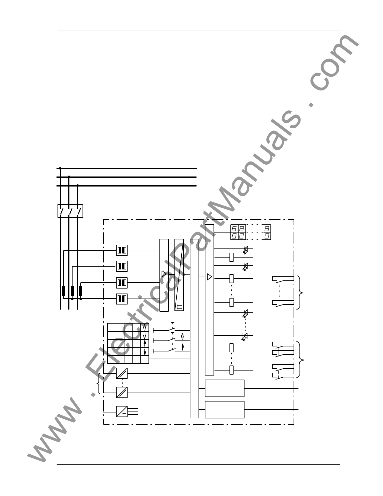
4.1 Operation of complete unit
The numerical circuit breaker failure protection
7SV512 is equipped with a powerful and proven
16---bit microprocessor. This provides fully digital
processing of all functions from data acquisition of
measured values to trip signal output to the circuit
breakers.
Figure 4.1 shows the basic structure of the unit.
The transducers of the measured value input section ME transform the currents from the measurement transformers of the switch-gear and match
them to the internal processing level of the unit.
Apart from galvanic and low-capacitance isolation
provided by the input transformers, filters are provided for the suppression of interference. The filters
have been optimized with regard to bandwidth and
Serial
interface
Serial
interface
Personal
computer
Power
supply
10 binary
inputs
Operator
panel
M/S
ME AE
Ç
LED--Reset
CW 7 8 9
R
F
DA
4 5 6
1 2 3
0 ¡ 1
J/Y
N +/--- E
C
L1
L2
L3
Busbar
Feeder
breaker
LCD display
(2 x 16
characters)
8 signals
(can be marshalled)
5 x 2 trip commands (can be
marshalled)
Control centre
Fault
Ready
6 LED (can be
marshalled)
Figure 4.1 Hard-ware structure of the numerical circuit breaker failure protection relay 7SV512
www . ElectricalPartManuals . com

Method of operation7SV512
V1
24
C53000---G1176---C91
processing speed to suit the measured value processing. The matched analog values are then
passed to the analog input section AE.
The analog input section AE contains input amplifiers, sample and hold elements for each input, analog---to---digital converters and memory circuits for
the data transfer to the microprocessor.
Apart from control and supervision of the measured
values, the microprocessor processes the actual
protective functions. These include in particular:
--- filtering and formationof themeasured quantities,
--- continuous interrogation ofthe binary inputwhich
are used for initiation,
--- continuous calculation of the currents,
--- plausibility checks on the measured currents and
the starting conditions,
--- scanning of limit values and time sequences,
--- decision on trip commands,
--- Storage of instantaneous current and voltage values during a fault for analysis.
Binary inputs andoutputs to andfrom the processor
are channelled via the input/output elements. From
these the processor receives information from the
switch-gear (e.g. remote resetting) or from other
equipment (e.g. blocking signals). Outputs include,
in particular, trip commands to the circuit breakers,
signals forremote signalling ofimportant events and
conditions aswell as visual indicators(LEDs) and an
alphanumerical display on the front.
An integrated membrane keyboard in connection
with a built-in alphanumerical LCD display enables
communication with the unit. All operational data
such as setting values, plant data, etc. are entered
intothe protection fromthispanel (refer Section6.3).
Using thispanel the parameters can berecalled and
the relevant data for the evaluation of a fault can be
readout aftera faulthas occurred(refer Section6.4).
The dialog with the relay can be carried out alternatively via the serial interface on the front plate by
means ofan operator panel or apersonal computer.
Via a second serial interface (option), fault data can
be transmitted to a central evaluation unit. During
healthy operation, measured values (e.g. load currents) canalsobe transmitted. This secondinterface
is designed for connection of optical fibre links, provided this interface is accordingly ordered (refer
Section 2.3 Ordering data).
A powersupply unit provides theauxiliary supply on
the variousvoltage levels tothe described functional
units. +18 Vis used forthe relay output circuits. The
analog input circuitsrequire ±15 Vwhereas the processor and its immediate peripherals are supplied
with+5 V. Transient failures inthe supply voltage, up
to 50 ms, which may occur during short-circuits in
thedc supplysystem ofthe plant arebridged bya dc
voltage storage element (rated auxiliary voltage
>110 Vdc).
www . ElectricalPartManuals . com
Method of operation7SV512
V1
25C53000---G1176---C91
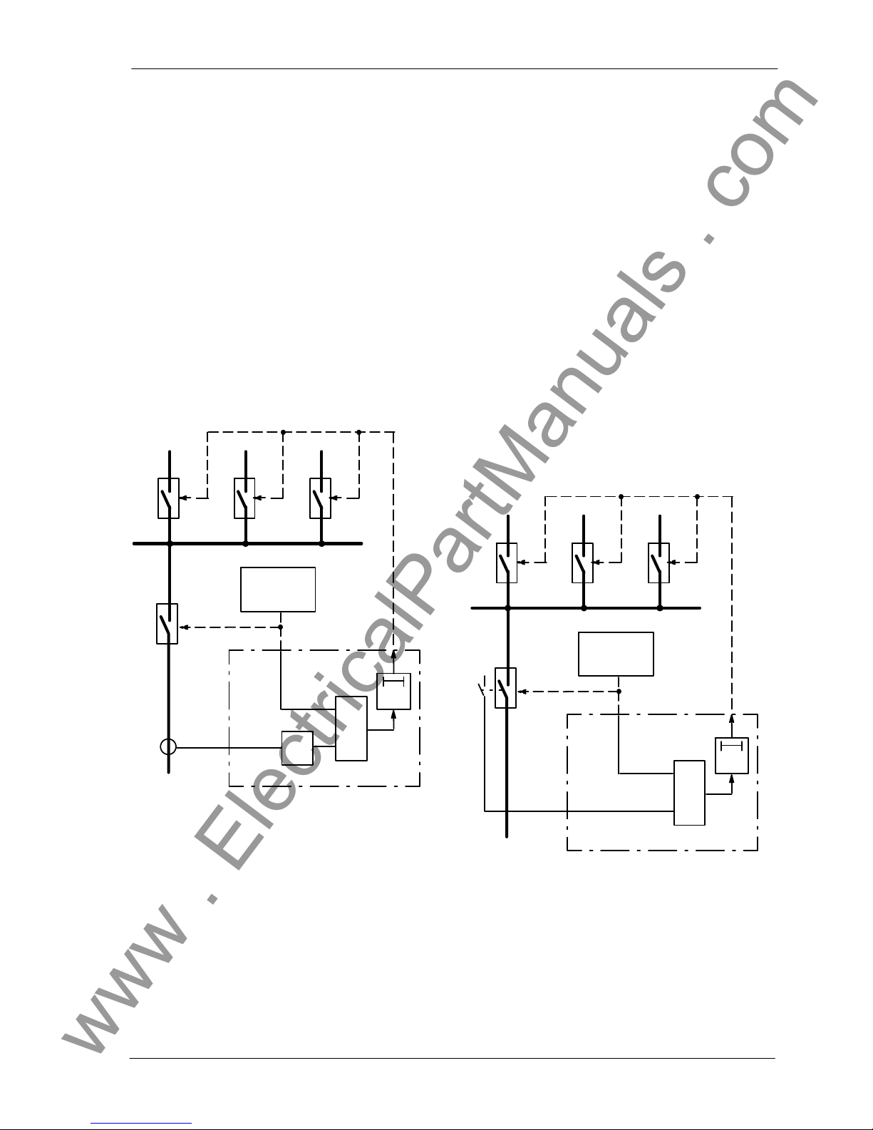
4.2 Circuit breaker failure protection
4.2.1 General
The circuit breaker failure protection provides rapid
back-up clearance of fault, in the event that the circuit breaker fails torespond to atrip command from
the feeder protection.
Whenever e.g. a short-circuit protection relay of a
feeder issues a trip command to the breaker, this is
repeated to the circuit breaker failure protection. A
timer T---BF in the breaker failure protection is
started. The timer runs as long as a tripping command is present and current continues to flow
through the breaker poles (Figure 4.2).
feeder
protection
I---
BF
&
T--BF
protection
trip
Trip bus-bar
circuit breaker
failure protection
7SV512
feeder
bus
bar
Figure 4.2 Simplified function diagram of circuit
breaker failure protection
Normally, the breaker will open and interrupt the
fault current. The current monitoring stage quickly
resets (typical 10 ms) and stops the timer.
If the tripping command is not carried out (breaker
failure case), current continues to flow andthe timer
runs to its set value. The breaker failure protection
then issues acommand to tripthe back-up breakers
and interrupt the fault current.
Thereset time ofthefeeder protection isof noimportance because the breaker failure protection itself
recognizes the interruption of the current.
For protection relays for which the tripping criteria
are notdependant on current(e.g. Buchholz protection), current flowis nota reliable criterion for proper
operation of the breaker.
Inthe suchcases, the circuitbreaker position canbe
read from the auxiliary contacts of the breaker.
Therefore, instead of monitoring the current, the
condition of the auxiliary contacts is monitored. For
that purpose, theoutputs from the auxiliarycontacts
must be fed to binary inputs on the relay (refer also
Section 4.2.3).
&
7SV512
L
+
feeder
protection
protection
trip
Trip bus-bar
circuit breaker
failure protection
feeder
bus
bar
T--BF
Figure 4.3 Simplified function diagram of circuit
breaker failure protection controlled
by circuit breaker auxiliary contact
In addition to this basic operation sequence,
7SV512 contains further possibilities which are described in detail in the following sections.
www . ElectricalPartManuals . com
Method of operation7SV512
V1
26
C53000---G1176---C91
4.2.2 Current flow monitoring
Each ofthe phase currents andan additional plausibility current (see below) are filtered by two-stage
numerical filter algorithms so that only the fundamental frequency is used for further evaluation. The
filters are designed such that the occurrence and
the disappearance of a sinusoidal current is detected within less than a half a.c. period.
Particular features apply for recognition of the instant of interruption. With sinusoidal currents, currentinterruption is detected afterapprox. 5to 10 ms.
With aperiodic d.c. current components in the fault
current andafter interruption (e.g. withlinear current
transformers) or ifthe current transformers are saturated by the d.c. component in the fault current, it
can take up to one a.c. cycle, with extreme conditions, before the disappearance of the primary current is reliably detected.
Fourcurrents are monitored and compared with the
set threshold. Besides the three phase currents, a
fourth current threshold is provided in order to detect a plausibility current, normally the earth current
(residual current). This does not have any direct influence on the basic function of the breaker failure
protection butitallows a2 -out-of-4 comparisonto be
made (refer Figure 4.4). This means that the current
detection signal LK> associated with a phase cur rent ILKcan only be generated when current is present in at least one of the other phases, or an earth
(residual) current is detected.
With a phase-to-phase fault, current flows in at least
two poles of the breaker; with a single-phase fault,
an earth current is always present (residual sum of
the phase currents) if only one pole carries current.
Thus, on the onehand, detection of the fault current
and start of the timer is guaranteed. On the other
hand, the 2-out-of-4 logic provides high security
against false operation.
Three times the negative sequence current of the
symmetrical current components can be taken as
plausibility current in case the earth current is not
available. This negative sequence current is calculated by 7SV512 (Figure 4.5). The negative sequence current I2is calculated according to its definition equation:
3 ¡ I2= IL1+ a2¡ IL2+ a ¡ I
L3
where
a = e
j120
&
&
&
&
&
&
>
=
1
>
=
1
>
=
1
I
L1
I
L2
I
L3
I---BF
I---BF
I---BF
I
pl
I---BF
L1>
L2>
L3>
Figure 4.4 Current flow monitoring with 2-out-
of-4 check
I
L1
I
L2
I
L3
I
E
3¡I
2
I
pl
PLAUS 1POL
NEG.SEQ. CURRENT
RESIDUAL CURRENT
Figure 4.5 Plausibility current
www . ElectricalPartManuals . com
Method of operation7SV512
V1
27C53000---G1176---C91
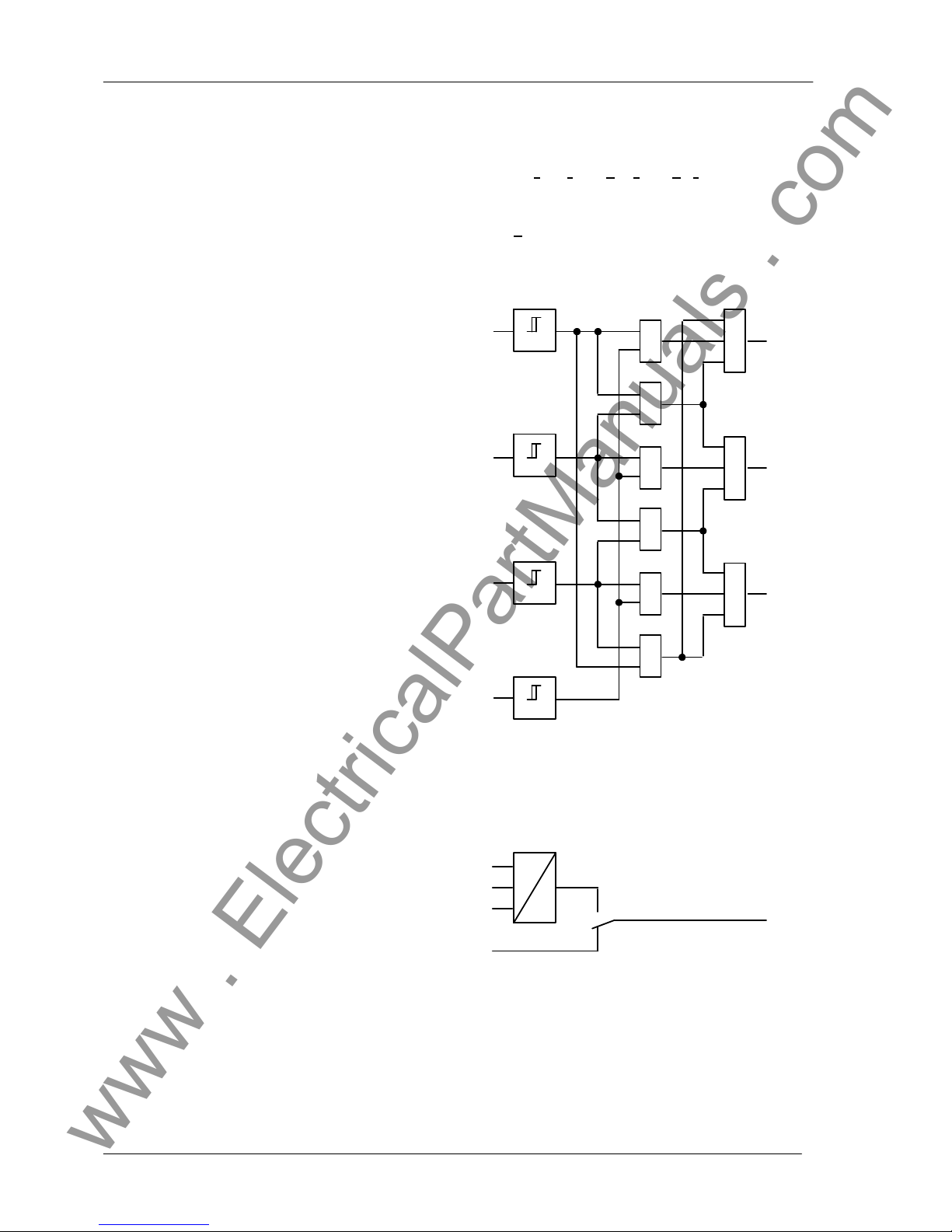
4.2.3 Processing of the circuit breaker auxiliary contacts
Current flowisnot areliable criterionfor properoperation of the circuit breaker for faults which do not
cause detectable current flow (e.g. Buchholz protection). Information about the position of the circuit
breaker auxiliary contacts is required in these cases
to check correct response of the circuit breaker. If
thebreaker poles can beswitched individually,information about the position of each individual circuit
breaker pole is useful (but not always a precondition).
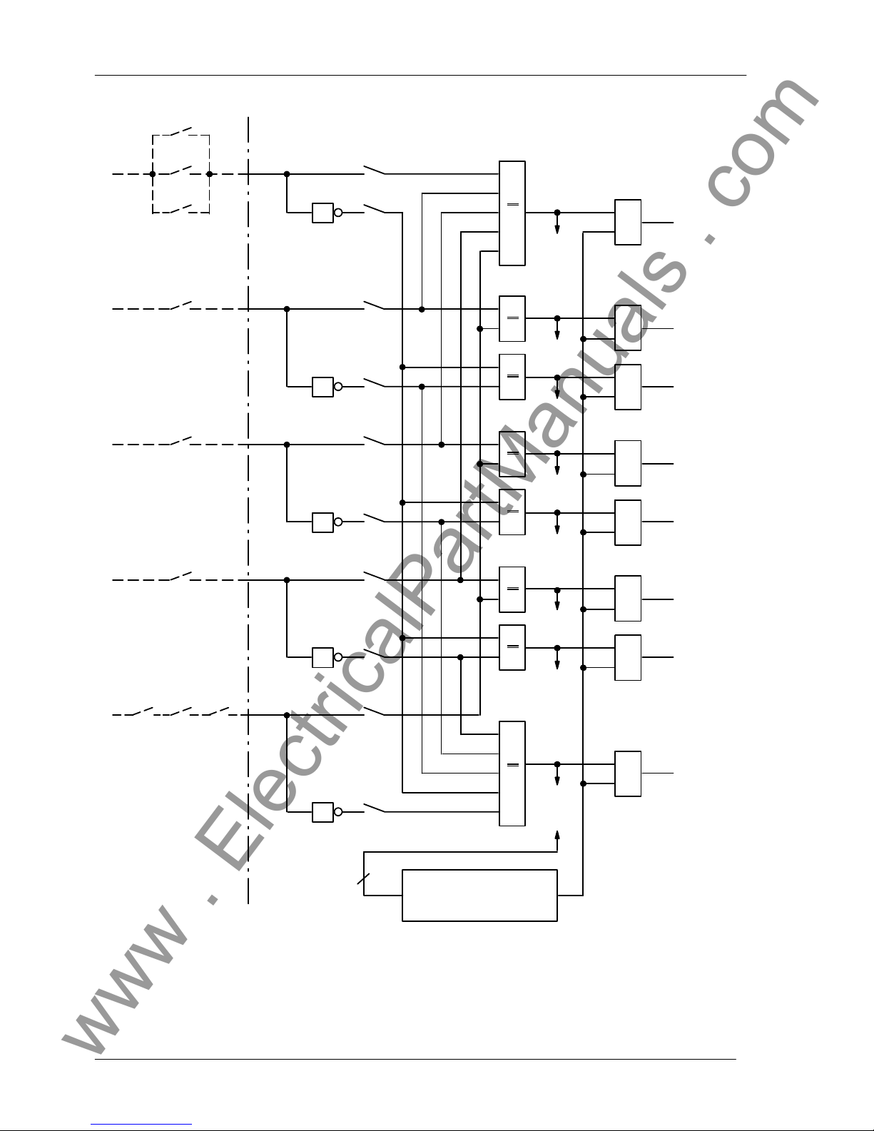
The relayincorporates a circuit breaker position logic (Figure4.7), which offers various possibilities, dependent of which auxiliary contacts are available
fromthe circuit breaker andhow theyare connected
to binary inputs of the relay.
If the circuit breaker is switched only three-pole, its
auxiliary contact isconnected to abinary input module which is assigned to the input function ”>CB
Aux. 1p C” (BI 20 in Figure 4.7). The remaining
inputs in the figure are not used then.
If the circuitbreaker poles can be switched individually but only the parallel connected auxiliary contacts are available, then thebinary input for thisconnection must be assigned exclusively to the input
function ”>CB Aux. 1p C” (BI 20 in Figure 4.7).
Theremaining inputs inthe figure arenot usedthen.
If the circuitbreaker poles can be switched individually and each individual auxiliary contact is available
then itis recommended toconnect the auxiliarycontact ofeach individual pole to anindividual binary input. Thisconnection allows maximum information to
be processed in the relay. The assignment of the
binary inputs is as follows:
--- auxiliary contact ofpoleL1 assigned toinput function ”>CB Aux. L1” (BI 16 in Figure 4.7),
--- auxiliary contact ofpoleL2 assigned toinput function ”>CB Aux. L2” (BI 17 in Figure 4.7),
--- auxiliary contact ofpoleL3 assigned toinput function ”>CB Aux. L3” (BI 18 in Figure 4.7).
Binary inputs BI 19 and BI 20 are not used in this
case. This connection mode is recommended if the
breaker failureprotection canbe initiated byafeeder
protection function which may trip at low-current or
no-current conditions and which shall operate in
conjunction with single-pole auto-reclosure (e.g.
weak-infeed trip with carrier transmission).
If the circuitbreaker poles can be switched individually but only twobinary inputs can be used, one can
connect the parallel connection of one set ofauxiliary contacts to a binary input and the series connection to another.The inputs are assigned to the function ”>CB Aux. 1p C” (BI 20 in Figure 4.7) for the
parallel connection and to ”>CB Aux. 3p C”(BI 19
inFigure 4.7)forthe seriesconnection. A single-pole
trip command is assumed to beexecuted, when the
series connection is interrupted.
Note that Figure 4.7 shows the total logic for all the
connection possibilities. In the actual case a part of
the inputs and logic is only used, as described
above.
The 8outputs ofthe circuit breakerposition logic are
processed by the protection functions. The output
signals are blocked as long as the input signals are
not plausible: e.g. a circuit breaker pole cannot be
open and closed at the same time.
Evaluation of the breaker auxiliary contacts is carriedout inthe breakerfailure protection functiononly
as long as the current flow monitoring has not
picked up. Once the current flow criterion has been
detected during trip signal of the protection, the circuit breaker is assumed to be open as soon as the
current hasdisappeared, even when the associated
auxiliary contact does not (yet) indicate that the circuit breaker has opened (Figure 4.6). This gives
preference to the more reliable current criterion and
avoids overfunctioning due to a defect e.g. in the
auxiliary contactmechanism orcircuit. This interlock
feature is provided for each individual phase as well
as for three-pole trip; in the latter case the ”any pole
closed” output as illustrated in Figure 4.7 is decisive
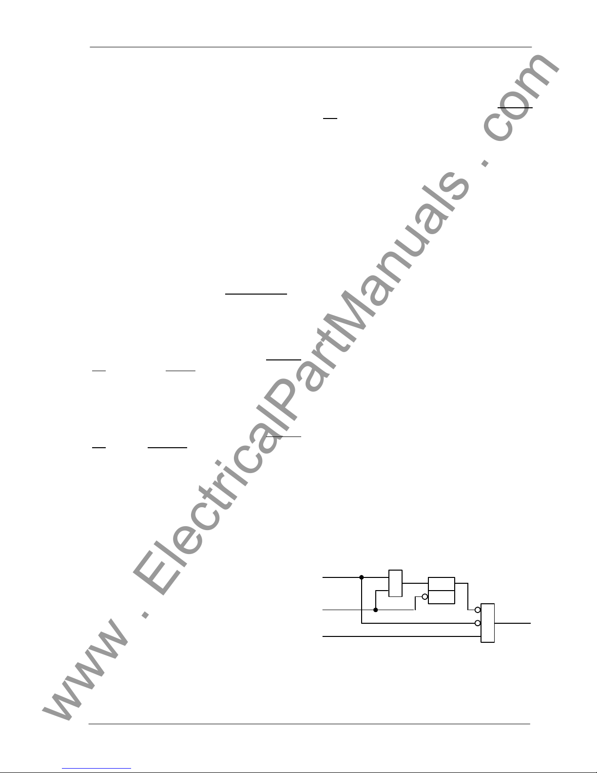
for the ”CB aux. contact” signal of Figure 4.6.
&
R
&
S Q
Auxiliary
contact
criterion
Aux
current
flow
prot.
trip
CB aux.
contact
Figure 4.6 Interlock of the auxiliary contact cri-
terion
www . ElectricalPartManuals . com
Method of operation7SV512
V1
28
C53000---G1176---C91
BI 20
A20
BI 16
>
1
>
1
>
1
BI 17
>
1
>
1
BI 18
>
1
>
1
BI 19
>
1
&
L1
L1
L2
L2
L3
L3
L2 L3L1
&
&
&
&
&
&
&
plausibility
check
8
A20
A16
A16
A17
A17
A18
A18
A19
A19
L1 closed
L1 open
any pole
closed
any pole
open
CB aux.contacts:
L1, L2, L3 Circuit breaker auxiliary contacts
BI .. Binary input with associated function number
A.. Binary input is assigned to physical input
L2 closed
L2 open
L3 closed
L3 open
Figure 4.7 Circuit breaker position logic
www . ElectricalPartManuals . com
Method of operation7SV512
V1
29C53000---G1176---C91
4.2.4 Initiation conditions and delay times
Because of the high safety demand for the breaker
failure protection, initiation from the main protection
must always be performed by energization of at
least two binary inputs (dual channel initiation). In
addition, special supervisory measures are provided (refer Section 4.2.7).
4.2.4.1 Common phase initiation
Common phase initiation is used, for example, for
lines without automatic reclosure (e.g. cables), for
lines with only three-pole auto-reclosure (e.g. in
overhead line systems without earthed neutral), for
transformer feeders, or if the bus-bar protection
trips.
For safety reasons, initiation can only be valid when
at least two binary inputs are energized. T oachieve
this, the main protection must deliver at least the
three-pole trip command at the input ”>Trip 3
pole” andan additional fault detection signal at the
input ”>Start”.ForBuchholz protection it isrecommended that the trip command is connected to
7SV512 by two separate wire pairs in order to
achieve dual channel initiation of the breaker failure
protection.
The function scheme is shown in Figure 4.8. When
the initiation conditions are fulfilled and at least one
current flow criterion (according Figure 4.4) is present, thedelay timeT1---3POLEis started. Afterexpiry
of this time, the trip command ”BFP Trip L123” is
issued.
>
1
&
&
&
T1 --3POLE
BFP
Trip L123
L1>
L2>
L3>
(acc.
Fig 4.4)
>Trip 3pole
>B/F
block
internal
blocking
>Start
Aux
(acc.
Fig 4.6)
Figure 4.8 Breaker failure protection with com-
mon phase initiation
7SV512 provides facility to interrogate the circuit
breaker auxiliarycontact(s) (according Figure4.6)in
casethe current flowcriterion isnot fulfilledfor anyof
the phases. If the circuit breaker poles can be
tripped individually, the parallel connection of the
three auxiliary contacts is used (signal ”any pole
closed” in Figure 4.7), or the OR combined signals
”L* closed”. The circuit breaker has operated correctly afterthree-pole trip command onlywhen none
of the phases carries current or when all three auxiliary contacts have opened.
Possibility exists to set different delay times dependent onwhether the current flowcriterion or theaux iliary contact criterion is fulfilled. Thus, e.g. a longer
timecan beset forthe auxiliarycontact criterionifthe
auxiliary contacts could react slower. To achieve
this, thedelay times T2 areused, i.e.the breaker failure protection operates single-stage with T2; T1 is
ineffective. Initiation and current flow criterioncause
the time T2---CURRENT to be started, initiation and
auxiliary contact criterion cause the time T2---CB--AUX to be started (refer Figure 4.9).
>
1
&
&
&
T2 ---CB--AUX
BFP
Trip BB
L1>
L2>
L3>
(acc.
Fig 4.4)
>Trip 3pole
>B/F
block
internal
blocking
>Start
Aux
(acc.
Fig 4.6)
&
T2 --CURR.
>
1
Figure 4.9 Breaker failure protection with com-
mon phase initiation
Initiation can be blocked via the binary input ”>B/F
block” (e.g. during test of the feeder protection
relay). Additionally,an internal blocking possibility is
provided (refer also Section 4.2.7).
www . ElectricalPartManuals . com

Method of operation7SV512
V1
30
C53000---G1176---C91
4.2.4.2 Two-stage breaker failure protection
with common phase initiation
Two-stage protection means that two timers (orsets
of timers) withdifferent delay times are started. After
expiry of the first stage T1, the trip command of the
feeder protection is normally repeated onthe feeder
circuit breaker, often on a second trip coil (local trip
orcross trip), ifthe breakerhas notresponded tothe
original tripcommand. Asecond time stage T2monitors the response to this repeated trip command
and trips the breakers of the relevant bus-bar section, if the fault is not yet cleared after this time. A
choice can be made whether the two timers are
started at the same time or one after the other.
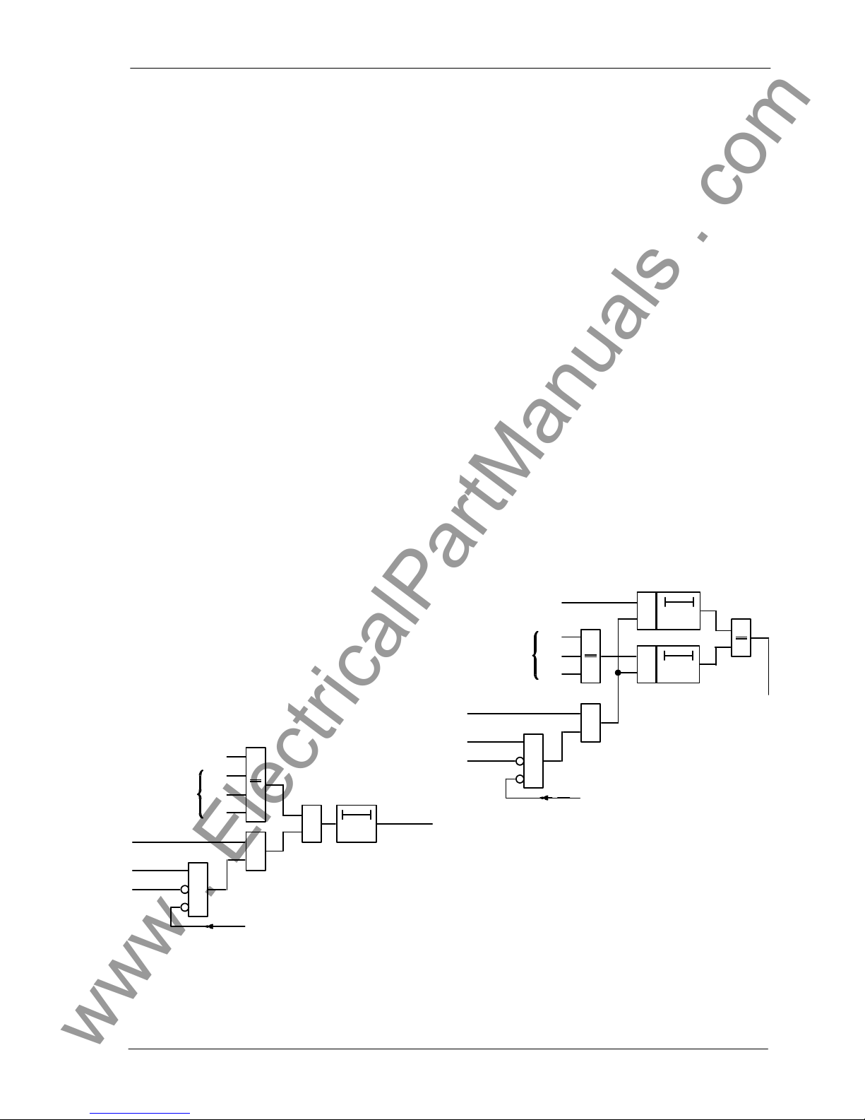
The functional scheme is shown in Figure 4.10. The
operation sequence of the first stage is, in principle,
the same as that ofthe single-stage example shown
in Figure 4.8 (refer Section 4.2.4.1). After expiry of
the timeT1---3POLE, thetrip commands ”BFP Trip
L123” and ”BFP Cross Trip” are generated
which normally repeat the command for the feeder
circuit breaker(local trip orcross trip). After expiryof
the second time stage, the bus-bar (section) is disconnected by the command ”BFP Trip BB”.
With the second stage, distinction can be made between start by means of the current criterion
T2---CURRENT or bymeans ofthe auxiliary contact
criterion T2 ---CB---AUX.Thus, e.g. a longer time can
beset forthe auxiliary contactcriterion ifthe auxiliary
contacts may react slower.
The parameter switch T---TRIP---BB determines
whether the timers T2 can be started only after T1
has expired (times operate in sequence) or whether
the timers T2 are started with T1 at the same time
(times operatein parallel). Thefirst possibilitymeans
that T2starts withthe tripcommand ofthefirst stage,
in the second case both timers start with the initial
trip command of the feeder protection.
>
1
&
&
&
T1 --3POLE
BFP
Trip L123
L1>
L2>
L3>
(acc.
Fig 4.4)
>Trip 3pole
>B/F
Block.
internal
blocking
>Start
Aux
(acc.
Fig 4.6)
>
1
&
&
&
>
1
”1”
”1”
T---TRIP---BB
T2
T1+T2
T2 ---CB--AUX
T2 --CURR.
BFP
Trip BB
BFP
CrossTrip
Figure 4.10 T wo-stage breaker failure protection with common phase initiation
4.2.4.3 Phase segregated initiation
Phase segregated initiation isnecessary ifthe circuit
breaker poles can be switched individually, e.g. if
single-pole auto-reclosure is used.
For safety reasons, initiation can only be valid when
at least two binary inputs are energized. T oachieve
this, the main protection must deliver, besides the
three single-pole trip commands at the inputs
”>Trip L1”, ”>Trip L2”, and ”>Trip L3”, at
least an additional fault detection signal at the input
”>Start”. In addition, earth fault detection can be
connected to ”>Start N”.
The initiation logic is shown, in principle, in Figure
4.11, if the feeder protection is able to give phase
segregated trip commands. Similar to the logic of
current flow monitoring (Section 4.2.2), a 2-out-of-4
logic isused. That means, thatinitiation ofa phase is
valid only when at least a trip command of another
phase is present, or an earth fault is detected
(”>Start N”). Additional safety is achieved in that
the general fault detection signal of the feeder protection is required. In case the feeder protection
relay does not output theearth fault detection, it can
be omitted; the fault detection signal ”>Start” ensures, nevertheless, dual channel processing of the
trip criteria in any case.
www . ElectricalPartManuals . com
 Loading...