


UHF-R Service Manual
25-1099
UR4D RECEIVER
PRODUCT DESCRIPTION
GENERAL
The UR4D (Dual Channel) and UR4S (Single Channel) are top the the line UHF band Wireless microphone receivers. Each unit is housed in a single space, metal rack-rack mount chassis. The product is designed in five different frequency Groups spanning from 518 MHz to 865 MHz.
® |
RF |
Audio |
ABJ 779-810 MHz |
Navigate |
RF |
Audio |
ABJ 779-810 MHz |
Navigate |
Control |
Monitor |
Power |
|
|||||||||||
|
|
|
|
|
|
|
|
|
|
1 |
|
|
OL |
|
|
|
OL |
|
|
ENTER |
|
2 |
|
|
|
|
|
|
|
|
|
|
|
||
UR4D |
|
|
|
|
|
|
|
|
|
push |
|
|
|
|
|
|
|
|
|
|
Monitor Clip |
|
|
Wireless Receiver |
|
|
|
|
|
|
|
EXIT |
|
|
|
with Audio Reference |
|
|
|
|
|
|
|
|
|
|
|
Companding |
|
|
|
|
|
|
|
|
|
|
|
sync |
|
|
|
|
|
|
|
|
sync |
|
|
|
|
|
|
|
|
|
|
|
|
|
DESIGN FEATURES
•Narrow band track tuned front-end filters.
•Synthesized tuning with 25kHz steps.
•High dynamic range LNA and double balanced mixers for maximum compatibility.
•As many as 40 compatible channels within each 60Mhz band.
•Front panel LED indication of RSSI and RF overload.
•Full MARCAD diversity.
•Tonekey squelching.
•ASK modulated tonekey sends transmitter data to receiver.
•Audio Reference Companding noise reduction system.
•Front panel LED indication of audio signal level.
•Isolated XLR and ¼” balanced outputs.
•Mic/Line switch on XLR output.
•Pin 1 lift for both XLR and ¼” outputs.
•Headphone monitor with separate clip indicator.
•Bitmap LCD displays.
•Bi-directional IR link for data communication with UHF-R transmitters.
•Ethernet and USB connectivity for control and metering.
•Universal switching power supply with daisy chain power connector.
Service Note: Shure recommends that all service procedures be perform by a Factory-Authorized Service Center or that the Product be returned directly to Shure Incorporated.
©2005, Shure Incorporated |
Printed in U.S.A. |
25-1099 (Rev. 1) |
|
18
17
3 |
|
|
|
|
|
|
|
|
|
|
|
|
|
|
|
|
2 |
4 |
|
5 |
|
|
|
|
|
|
RF |
Audio |
XX YYY-ZZZ MHz |
Navigate |
RF |
Audio |
XX YYY-ZZZ MHz |
Navigate |
|
Control |
Monitor |
POWER |
|
|
|
|
|
|
|
|
|
|
OFF |
|
|
UR4D |
OL |
|
|
|
OL |
|
|
|
ENTER |
|
|
|
|
|
|
|
|
|
|
push |
|
|
|||
Wireless Receiver |
|
|
|
|
|
|
|
|
|
|
|
|
|
|
|
|
|
|
|
|
|
Monitor Clip |
|
|
|
with Audio Reference |
|
|
|
|
|
|
|
|
EXIT |
|
|
|
Companding |
|
|
|
|
|
|
|
|
|
|
|
|
|
|
|
|
|
|
|
|
push |
|
|
|
|
sync |
A |
B |
|
|
A |
B |
|
|
|
|
|
|
|
|
|
|
|
|
|
|
|||||
|
|
|
|
|
|
|
|
6 |
|
|
7 |
8 |
|
|
|
antenna B in |
|
|
receiver outputs |
|
networking |
|
receiver outputs |
antenna A in |
|
|
|
|
balanced low Z |
|
|
|
balanced low Z |
|
||||
|
|
|
|
|
200Ω |
|
|
200Ω |
|
|
||
|
|
|
|
|
|
|
|
|
|
|
||
|
|
|
|
|
|
|
|
network |
|
|
|
|
|
|
|
|
|
|
|
|
activity |
|
|
|
|
|
|
|
12.7V out |
line |
|
lift |
|
ethernet |
line |
lift |
12.7V |
out |
|
|
|
mic |
|
GND |
|
mic |
GND |
||||
|
|
|
150mA |
|
|
|
|
RJ-45 |
|
|
150mA |
|
|
|
|
|
|
|
|
|
|
|
|
|
|
9 |
10 |
11 |
12 |
13 |
14 |
15 |
16 |
17 |
11 |
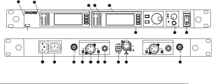
FIGURE 1. UR4D AND UR4S FRONT AND REAR PANELS
Receiver Controls and Connectors
1.SYNC Infrared (IR) port. Transmits group, channel, and other settings to a transmitter.
2.Squelch LEDs.
•Blue (On) = Transmitter signal detected
•Off = no signal or signal squelched because of poor reception or no tonekey NOTE: The receiver will not output audio unless at least one blue LED is illuminated.
3. RF LEDs. Indicate RF signal strength from the transmitter at each antenna and diversity condition.
•Amber = normal
•Red = overload (greater than –25 dBm)
4. Audio LEDs. Indicate audio signal strength from transmitter.
•Green = signal present
•Yellow = normal peak
•Red = overload
To correct this level, adjust the transmitter gain.
5.Indicates the name and range of receiver frequency band.
6.LCD Interface. Provides a convenient way to program the receiver from the front panel.
7.Monitor. 1/4” output jack and volume knob for headphones.
•Monitor Clip LED indicates headphone audio is clipping.
•Dual models: Push the knob to switch from receiver one to reiver two.
8.Power switch. Powers the unit on and off.
9.AC mains power input, IEC connector. 100–240 Vac.
10.AC mains power passthrough (unswitched). Use with an IEC extension cable to supply AC power to another device.
11.Diversity antenna inputs A and B.
Note: Antenna inputs are DC biased. Use only antenna combiners and accessories listed. Some types of antenna splitters or other products may short the DC power and damage the receiver. Bias can be removed through internal jumper setting.
12.Mic/Line switch. Changes output level –30 dB (XLR output only).
13.Electrically balanced XLR output jack
14.Lift/GND switch. Lifts ground from Pin 1 of the XLR connector (default = GND).
15.Impedance balanced 1/4” output jack (200Ω)
16.USB jack for computer interface.
17.RJ-45 jack for Ethernet network interface. Accepts both regular and “ruggedized” RJ-45 plugs.
18.Temperature-activated fan ensures top performance in high temperature environments. Clean fan screen as needed to remove dust.
25-1099 (Rev. 1) |
2 |
Standard Operating Conditions
Power Supply: 100 VAC to 240 VAC 50 to 60 Hz Temperature: -20C to 57C
RF: -80 to -20 dBm into 50 Ohms
FM Deviation: <45 kHz of 1KHz tone for THD<1%
Operating Information
The basic steps required for unit operation:
•Switch and control functions
•Basic Settings
•User Interface and Status Indication
UHF-R RECEIVER PROGRAMMNING
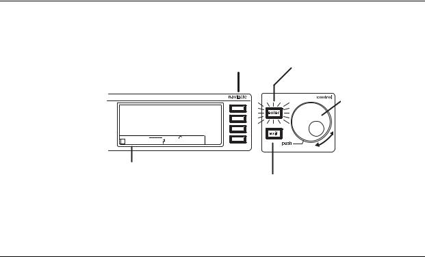
Receiver LCD Interface
Menu Access
Press the Navigate
key next to the menu
item you want
Accept Changes
After changing a parameter, the ENTER button flashes.
SHURE |
|
|
|
|
|
|
|
|
|
|
|
Radio |
|
524-025 MHz TV: 32 |
|
Audio |
|||||||||||
G: 3 Ch: 1 Out: -0dB |
|
Util |
|||||||||||
|
+12 dB |
|
|
|
|
|
|
|
|
|
Hi |
|
F, P, FP Sync |
+ |
|
|
|
|
|
|
|
|
|
|
|||
|
|
|
|
|
|
|
|
|
|
|
|||
Transmitter Status Display
Everything under the Exit/Cancel dotted line reflects the
settings for the transmitter, if present.
Cursor Control
Push the Control wheel to move the cursor to the next item.
Turn the Control wheel to change a
parameter value.
Press the Exit button to cancel changes and return to the previous
Receiver Parameters
Use the following instructions to set parameters through the LCD interface.
NOTE: After adjusting a parameter, you must press the flashing ENTER button to accept the change.
Group and Channel
Menu: Radio
•Push the Control wheel to move the cursor to the Group (G) or Channel (Ch) parameter.
•Turn the Control wheel to change the parameter.
Frequency
Menu: Radio
•Push the Control wheel to move the cursor to the integer value (741.000 MHz) or fractional value (741.025).
•Turn the Control wheel to change the value.
Automatic Transmitter Sync
Menu: Sync.
25-1099 (Rev. 1) |
3 |
Receiver Name
Menu: Util
•Turn the Control wheel to change the letter.
•Push the Control wheel to move to the next letter.
Output Level
Menu: Audio
This setting adjusts the signal level at the XLR and 1/4” audio output jacks.
•Turn the Control wheel to change the relative level in dB. (0 dB to –32 dB).
•Turn the wheel all the way down to mute the outputs.
Squelch
Menu: Radio > Squelch
• Turn the Control wheel to change the parameter
Receiver Lock
When locked, the receiver settings cannot be changed from the front panel. However, you can still navigate the LCD menu to view the settings (and turn the lock off).
Menu: Util > Lock
• Turn the Control wheel to toggle the lock on or off (ON or OFF).
LCD View
Menu: Util > Title
•Turn the Control wheel to mark an item for display.
•Push the Control wheel to move to the next item.
LCD Contrast
Menu: Util > Contrast
• Turn the Control wheel to increase or decrease contrast.
Tonekey
Menu: Radio > Squelch > Tonekey
Tonekey squelch mutes the outputs unless the receiver detects a transmitter. Tonekey should be left on (On) except for certain troubleshooting operations.
25-1099 (Rev. 1) |
4 |
Network Parameters
NOTE:
•The receiver reboots after you press ENTER to accept network parameter changes
•In dual models (UR4D), these settings affect both receivers (the dual receiver is treated as a single network device).
Set the Receiver Network Mode
Menu: Util > Network
1.Push the Control wheel to move the cursor to the Mode parameter.
2.Turn the Control wheel to set the receiver to one of the following values:
• DHCP: use this setting when connecting the receiver to a DHCP server.
• Manual: allows you to set the receiver to a specific IP address or subnet.
IP Address and Subnet
Menu: Util > Network
NOTE: To change these settings, the network mode must be set to Manual.
1. Push the Control wheel to move the cursor to any of the following parameters:
•IP (IP address)
•Sub (Subnet mask)
2. Turn the Control wheel to change the value.
Device ID
Assists in identifying receivers through the Wireless Workbench Software (has no effect on network identification). Menu: Util > Network
1.Push the Control wheel to move the cursor to the DevID parameter.
2.Turn the Control wheel to set the receiver to change the value.
Custom Groups
This feature allows you to create your own groups of frequencies.
Creating new groups...
Menu: Radio > Custom
1.Turn the Control wheel to select a custom group number (U1, U2, U3, etc.)
2.Push the Control wheel to move to the Channel parameter and turn it to select a channel (01, 02, 03, etc.)
3.Push the Control wheel to move to the Freq parameter and select a frequency for that channel.
4.Push the NEXT menu key to select a frequency for the next channel in that group.
Follow these steps to use the channel scan and group scan features.
25-1099 (Rev. 1) |
5 |

Automatic Frequency Selection
Before you begin...
•Install the receivers in the location where they will be used and power them on.
•Mute all inputs on mixing devices connected to receivers.
•Turn off all bodypack or handheld transmitters for the systems you are setting up.
•Turn on potential sources of interference such as other wireless systems or devices, computers, CD players, effects processors, and digital rack equipment so they are operating as they would be during the presentation or performance.
Single Receiver
1.Select Radio > Scan > Chan Scan using the Navigate keys on the receiver LCD interface.
2.Turn the Control wheel to select a group.
3.Press Chan Scan. The display indicates that the receiver is searching. Once it has finished, it displays the selected channel.
4.Press the flashing ENTER button to accept the suggested channel.
5.Sync the transmitter (see page 15).
Networked or Dual Receivers
With networked or dual receivers, you can take advantage of the group scan feature to set group and channel settings for all the receivers at the same time. (See page 7 for instructions on networking.)
Perform a group scan from any receiver...
1.Select Radio > Scan > Group Scan using the Navigate keys on the receiver LCD interface. The display indicates that the receiver is searching (Scan In Progress). Once it has finished, it displays the group with the most open channels.
2.If you wish, turn the Control wheel to change groups. The number of open channels for each group is displayed.
3.Press the flashing ENTER button to set all receivers to open channels in that group.
NOTE: The group scan feature only works for receivers in the same frequency band. For example, if you did a group scan on a “H4” band receiver, all “H4” band receivers would be set up, but not “J5” band receivers.
Multiple Receivers—Not Networked
If your receivers are not networked (or in different bands), the group scan cannot automatically set their group and channel settings. However, you can still take advantage of the group scan feature to find the group with the most open channels and the channel scan feature to find open channels in that group.
Find the group with the most open channels...
Perform a group scan using the steps for a networked receiver (above). However, make a note of the selected group before pressing the flashing ENTER button to accept it.
Set the receivers to open channels in that group...
Perform a channel scan on the remaining receivers using the steps for a single receiver (above). Make sure to select the same group for each receiver before performing the channel scan.
IMPORTANT: After setting the channel for the first receiver, immediately sync the transmitter for that receiver and leave it on so that the next receiver detects that channel during its channel scan. Otherwise, all the receivers will be set to the same open channel.
NOTE: Receivers in different bands (H4, J5, L3, etc.) do not need to be set to the same group.
25-1099 (Rev. 1) |
6 |
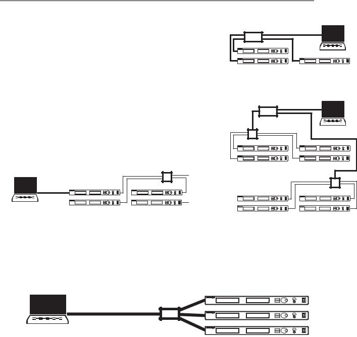
Networking Receivers
Basic Network
Connect receivers to an Ethernet router with DHCP service. Use Ethernet switches to extend the network for larger installations.
Use the receiver’s default network setting (Util > Network > Mode = DHCP).
Accessing the Network with a Computer
If you want to use the Wireless Workbench software, connect your computer to the network and install the software from the CD that came with the receiver. Make sure your computer is configured for DHCP (from Control Panel, click Network Connections. Double-click on Local Area Connection. Select Internet Protocol (TCP/IP) and click Properties. Select Obtain IP address automatically and Obtain DNS server address automatically and click OK).
NOTE: Some security software or firewall settings on your computer can prevent you from connecting to the receivers. If using firewall software, allow connections on port 2201.
Using USB...
Router with DHCP
Router with DHCP
Switch
Computer
(optional)
Computer
(optional)
Connect the computer to the USB port on any of the receivers to access the whole network.
Ethernet |
Switch |
|
USB
Static IP Addressing
The receiver also supports static IP addressing. Assign your own IP addresses ( Util > Network > Mode = Manual). See “Network Parameters” on page 10.
NOTE: Dual receivers use a single IP address, which may be set through either LCD interface.
Existing UHF Network Installations
Both Shure’s UHF-R receivers and legacy UHF receivers can be networked to the same PC and accessed using the latest Wireless Workbench software.
ETHERNET
25-1099 (Rev. 1) |
7 |
Theory of Operation and Design
Top Level Architecture
|
8,2 |
52 $ |
|
|
|
|
|
|
MIC LINE |
|
|
|
SWITCH |
|
|
|
gg |
(EADPHONE |
|
|
'ROUND LIFT |
||
|
!MP |
|
|
|
SWITCH |
|
|
|
|
|
|
|
|
|
|
|
2ECEIVER #HANNEL |
,%$3 |
|
!NTENNA |
|
6OLUME |
|
! |
|
|
|
|
2& SECTION ! |
!UDIO SECTION ! |
#( |
|
4OGGLE |
||
|
|
#LIP |
|
|
3PLITTER |
|
|
|
2& SECTION " |
!UDIO SECTION " |
|
53"
-ICRO PROCESSOR
%THERNET
!NTENNA |
2ECEIVER #HANNEL |
|
2& SECTION !  !UDIO SECTION !
 3PLITTER
2& SECTION "  !UDIO SECTION "
#HANNEL $ISPLAY AND CONTROLS
#HANNEL $ISPLAY AND CONTROLS
gg -ONITOR
3OFT +EYS


 %NCODER
|
|
,#$ |
|
|
|
|
|
|
|
|
|
$3 |
|
|
|
|
|
||
,% |
|
||
|
|
||
|
|
|
|
$ISPLAY |
|
||
|
|
||
3OFT +EYS
|
|
,#$ |
|
|
|
|
|
|
|
|
|
3 |
|
|
|
,%$ |
|
|
|
|
|
|
|
|
|
|
|
)2
8,2 |
|
|
|
|
|
|
|
|
|
4O |
|
MIC LINE |
0OWER |
|
|
|
|
|
|
|
6$# |
||
|
|
|
|
|
|
|
|||||
3WITCH |
|
|
3WITCHING |
|
|
6$# |
|||||
SWITCH |
|
|
|
|
|||||||
|
|
|
|
0OWER 3UPPLY |
|
|
|
||||
|
|
|
|
|
|
|
6$# |
||||
|
|
|
|
|
|
|
|
|
|
||
|
|
|
|
|
|
|
|
|
|
|
|
gg |
|
|
|
|
|
|
|
|
|
|
'ROUND |
|
|
|
|
|
|
|
|
|
|
||
|
|
|
|
|
|
|
|
|
|
||
|
|
|
). |
|
$AISY #HAIN |
|
|
||||
|
|
|
|
|
|
|
|||||
'ROUND LIFT |
|
|
|
|
|
|
|
/UT |
|
|
|
|
|
|
|
|
|
|
|
|
|||
SWITCH |
|
|
|
|
|
|
|
|
|
|
|
|
|
|
|
|
|
|
|
|
|
|
|
|
|
|
|
|
|
|
TO 6!# |
|
|
||
|
|
|
|
|
|
|
)%# |
|
|
|
|
25-1099 (Rev. 1) |
8 |

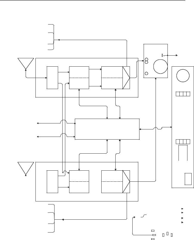
CIRCUIT DESCRIPTION
General Block Diagram Description
The UR4D/S incorporates four separate PC boards: 190-044 main board, 190-045 Microprocessor board, 190-046 Display Board, and 190-043 Headphone amp board. The product is powered by a 3” X 5” universal switching power supply that provides +15V, -15V, and +5V. Power from the switching power supply is connected to the 190-044 main board and distributed from the main board to the remaining boards. +3.3V for the microprocessor is derived from +5V by a linear regulator on the main board.
85 ' 5) %ORFN 'LDJUDP
|
|
|
|
|
|
|
|
|
|
|
|
|
RYHUORDG GHWHFWRU |
|
|
|
|
|||||
$QWHQQD $ |
|
|
|
|
|
|
|
|
|
|
|
|
|
|
|
|
|
|
|
|
|
|
|
|
GRXEOH |
|
|
|
|
|
|
|
|
|
|
|
|
|
|
|
|
&+ $ 5) RYHUORDG |
|
||
|
|
|
|
|
|
|
|
|
|
|
|
|
|
|
|
|
|
|
|
|
|
|
|
|
|
|
|
|
|
|
|
|
|
|
0+] |
|
|
|
|
|
|
||||
SROH WUDFNLQJ |
G% |
SROH WUDFNLQJ |
EDODQFHG |
0+] |
G% |
QG ,PDJH |
|
|
|
|
|
|
|
|
|
|
|
|
||||
|
|
|
|
|
|
|
|
QG ,) |
|
|
|
|
||||||||||
ILOWHU |
/1$ |
ILOWHU |
PL[HU |
6$: |
,) *DLQ |
)LOWHU |
|
|
|
|
|
|
|
|
4XDGUDWXUH |
|
|
|||||
|
|
|
|
|
|
|
|
|
|
|
|
|
|
|
)LOWHUV |
|
'HWHFWRU |
&KDQQHO $ |
||||
|
|
|
|
|
|
|
|
|
|
|
|
|
|
|
|
|
|
|
|
|
|
|
VSOLWWHU
IXVH
G%P |
QG PL[HU DQG |
|
,)*DLQ ,& |
|
$XGLR |
|
1RLVH |
|
|
|
566, |
|
&+ 7UDFN 7XQH FRQWURO |
|
|
|
|
|
|
|
|
|
MXPSHU |
3// FRQWUROHG VW /2 |
|
|
|
|
QG /2 |
|
|
|
|
|
+DUPRQLF |
|
+DUPRQLF |
|
|
|
|
|||
|
|
|
G% |
|
|
|
|
|||
|
|
9&2 |
ILOWHU |
ILOWHU |
|
|
VSOLWWHU |
|
|
|
9'& |
ORRS ILOWHU |
*DLQ |
VSOLWWHU |
|
|
|
||||
|
|
|
|
|
|
|
||||
P$ |
|
G%P |
|
|
|
|
|
|
|
|
|
|
|
|
|
|
|
|
+DUPRQLF |
|
|
|
|
|
|
|
|
|
0+] |
ILOWHU |
|
|
|
|
|
9&2 FRXUVH WXQH |
|
|
|
|
|
||
|
0+] |
|
|
|
|
|
|
|
||
|
|
|
|
|
|
|
|
|
|
|
|
|
|
&ORFN |
|
|
|
|
|
|
|
|
6\QWKHVL]HU |
'DWD |
|
|
|
|
RYHUORDG GHWHFWRU |
|
||
|
/RDG HQDEOH |
|
|
|
|
|
|
|
||
|
|
|
|
|
|
|
|
&+ % 5) RYHUORDG |
||
|
|
|
|
|
|
|
|
|
||
|
|
|
|
|
|
|
|
0+] |
|
|
|
|
|
|
|
G%P |
|
|
QG ,) |
4XDGUDWXUH |
|
|
|
|
|
|
|
|
)LOWHUV |
|
||
|
|
|
|
|
|
|
|
|
||
|
|
|
|
|
|
|
|
|
'HWHFWRU |
&KDQQHO % |
|
|
|
|
|
|
|
|
|
|
|
|
|
|
|
|
|
|
|
|
|
$XGLR |
|
|
|
|
|
|
|
|
|
|
1RLVH |
|
|
|
|
|
|
|
|
|
|
|
|
SROH WUDFNLQJ |
G% |
SROH WUDFNLQJ |
GRXEOH |
0+] |
G% |
QG ,PDJH |
QG PL[HU DQG |
|
566, |
|
ILOWHU |
/1$ |
ILOWHU |
EDODQFHG |
6$: |
,) *DLQ |
)LOWHU |
,)*DLQ ,& |
|
|
|
|
|
|
PL[HU |
|
|
|
RYHUORDG GHWHFWRU |
|
|
|
|
|
|
|
|
|
|
|
||
|
|
|
|
|
|
|
|
|
&+ $ 5) RYHUORDG |
|
|
|
|
GRXEOH |
|
|
|
|
|
|
|
|
|
|
0+] |
|
|
SROH WUDFNLQJ |
G% |
SROH WUDFNLQJ |
EDODQFHG |
0+] |
G% |
QG ,PDJH |
|
|
|
|
|
|
|
QG ,) |
|
|
ILOWHU |
/1$ |
ILOWHU |
PL[HU |
6$: |
,) *DLQ |
)LOWHU |
|
|
|
|
|
|
|
)LOWHUV |
4XDGUDWXUH |
&KDQQHO $ |
|
|
|
|
|
|
|
|
|
|
|
|
|
|
|
'HWHFWRU |
|
|
|
|
|
|
$XGLR |
|
|
|
|
|
|
1RLVH |
|
|
|
|
|
|
|
|
|
G%P |
|
|
QG PL[HU DQG |
566, |
|
|
|
|
|
||
|
|
|
|
|
,)*DLQ ,& |
|
&+ 7UDFN 7XQH FRQWURO |
|
|
|
|
|
|
3// FRQWUROHG VW /2 |
+DUPRQLF |
|
+DUPRQLF |
QG /2 |
|
|
|
G% |
|
|
|||
9&2 |
ILOWHU |
ILOWHU |
|
VSOLWWHU |
|
|
*DLQ |
VSOLWWHU |
|
||||
ORRS ILOWHU |
G%P |
|
|
|
||
|
|
|
|
|
|
|
|
|
|
|
|
+DUPRQLF |
|
|
|
|
|
0+] |
ILOWHU |
|
|
9&2 FRXUVH WXQH |
|
|
|
|
|
0+] |
|
|
|
|
|
|
|
|
|
|
|
|
|
$QWHQQD % |
|
|
|
|
|
|
|
&ORFN |
|
|
|
|
|
6\QWKHVL]HU |
'DWD |
|
|
|
RYHUORDG GHWHFWRU |
|
/RDG HQDEOH |
|
|
|
|
||
|
|
|
|
|
||
|
|
|
|
&+ % 5) RYHUORDG |
||
|
|
|
|
|
||
|
0+] |
|
|
|
G%P |
QG ,) |
|
|
|
)LOWHUV |
4XDGUDWXUH |
&KDQQHO % |
||
|
||||
|
|
'HWHFWRU |
||
|
|
|
VSOLWWHU |
|
|
|
|
|
|
|
IXVH |
|
|
|
|
|
|
|
SROH WUDFNLQJ |
G% |
SROH WUDFNLQJ |
GRXEOH |
0+] |
G% |
QG ,PDJH |
QG PL[HU DQG |
ILOWHU |
/1$ |
ILOWHU |
EDODQFHG |
6$: |
,) *DLQ |
)LOWHU |
,)*DLQ ,& |
MXPSHU |
|
|
PL[HU |
|
|
|
|
|
$XGLR |
|
1RLVH |
|
|
|
566, |
9'&P$
25-1099 (Rev. 1) |
9 |
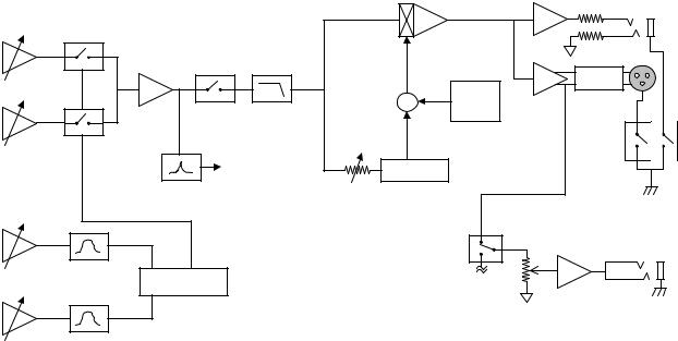
RF Sub System General Description
The receiver RF Sub System consists of all of the hardware needed to receive the wireless radio signal and convert it
into audio. It can be broken down into several sub-components: the antenna system, the front end, mixer, 1st IF, 2nd IF and detector. Each has an important part to play in determining the overall performance of the product. The UR4 receiver has two BNC input connectors, and will be supplied with a pair of detachable 1/2 wave antennas that can be remoted using accessory 50-Ohm cables if desired. Both single and dual receivers will use Shure’s MARCAD diversity for unsurpassed protection against signal dropouts.
UR4S and UR4D RF sections are located on the 190-044 main board. Each receiver channel in a UR4 system contains two RF sections referred to as sections A and B. Dual channel systems like the UR4D will contain 4 RF sections and will be referred to by CH1A, CH1B, CH2A, and CH2B. Single channel systems like the UR4S will use the CH2A and CH2B part of the 190-044 main board.
RF signals enter the UR4 receiver at the BNC ports labeled Antenna A In and Antenna B In. The receiver provides +12.4 VDC @ 150 mA at each antenna port for use with external RF amplifiers. Up to two external line amps, or one line amp and one active antenna can be driven from each antenna port. Power to the antenna ports can be removed via jumper settings on the 190-044 main board. UR4D systems passively split the signals present at each antenna port and send them equally to channels 1 and 2. UR4S systems send antenna signals directly to channel 2 without splitting. Receiver channels 1 and 2 are identical so operational descriptions of a single receive channel may be applied equally to both channels in a UR4D system.
Each RF channel requires +15V and +5V from the power supply.
Each channel frequency is user adjustable from the 190-046 display board. Several signals are derived from the channel frequency are used to automatically tune the RF section. The following tuning related signals are input to the RF section from the 190-045 microprocessor board: [(digital signals) Clock, Data, Load enable], [(DAC signals) VCO course Tune voltage, Track tune filter voltage].
The front end incorporates two track-tuned filters for superior protection from unwanted signals, while providing an industry leading 60 MHz of frequency coverage per SKU (slightly more in the higher frequency bands). Conversion to
the 1st IF is accomplished through a double balanced mixer to provide greatly improved RF dynamic range and system compatibility. The design also uses a 1st IF frequency of 110.6 MHz, together with a narrow SAW (Surface Acoustic
Wave) filter, to minimize spurious (unwanted) receiver responses. The Saw filter is followed by a 1St IF amp and 2 pole band-pass filter, providing improved sensitivity and second image rejection.
The 2nd IF consists of an integrated amplifier and mixer coupled with a discreet designed 99.9 MHz crystal oscillator.
The outputs from both 1st and 2nd local oscillators are shared between RF sections A and B. Demodulation produces the following baseband information signals: Audio (with Tonekey), and Noise. Each RF channel outputs the following respective information signals to the audio section of the 190-044 main board: Audio A, Audio B, Noise A, Noise B. A 32kHz ASK Tonekey signal is embedded within the audio signal and will be filtered and demodulated in the audio section of the 190-044 main board.
After conversion to the 2nd IF, the signal level present in each RF section is detected. A DC signal proportional to the
2nd IF level is created and referred to as the received signal strength indicator or RSSI. When antenna signals are within the receiver’s normal operating range the RSSI is displayed by a string of six LEDs on the 190-046 display board.
Antenna signals that exceed the maximum dynamic range of the receiver are detected in each 2nd IF section by separate RF overload circuitry. A DC signal proportional to the RF overload level is generated and used to activate a RF overload LED on the 190-046 display board. Each RF channel outputs the following respective DC signals to the 190-045 microprocessor board: RSSI A, RSSI B, RF overload A, RF overload B.
25-1099 (Rev. 1) |
10 |
Audio general description:
The audio, and noise outputs of the FM detector are trimmed for level and applied to the MARCAD circuit. The MARCAD circuit compares the noise of both channels and decides which audio channel, if not both, to pass. This circuit also compares noise levels to an overall minimum squelch level providing the noise squelch function. The chosen audio channel is fed to both a tonekey detection filter and a 20kHz low-pass filter via the tonekey mute switch. The output of the low-pass filter passes to the ARC expander section. User gain is summed into the VCA here for an adjustable range of 0 to –32 dB. The user can also mute the audio section from the audio menu. This is accomplished by turning off the tonekey mute switch. The output of the expander passes to the output drivers and on to the ¼” and XLR outputs. The XLR output has a 30 dB resistive pad that can be engaged by the user just before the output connector for best noise performance.
The tonekey detection filter is responsible for detecting presence of tonekey as well as conditioning the signal to be read by an ADC so that the encoded data can be read by the microprocessor. The output of the audio section immediately after the MARCAD switches is fed to two series connected high-Q 32kHz band-pass filters. These filters strip off both the modulated audio signal as well as any high frequency noise. The signal at this point is good enough to use to detect the amplitude-shifted data, but is not robust enough to be used for tonekey squelching. To provide the robust detection a 32kHz crystal filter is used. The output of the crystal filter is used to gate the input to ADC.
Audio signal metering is accomplished by a combination of two DC signals sent to corresponding ADCs. The first is a full wave peak detection tapped off just before the expander. This signal is used to give the user an idea of how transient signals, such as guitar, are propagating through the system. The second DC signal is derived from the output of the RMS detector portion of the expander. The RMS detector output is representative of the power contained in the signal averaged over a short period of time as well as how the compander is working. The microprocessor measures these two inputs and displays the appropriate LED output on the front panel.
The signal at the audio output is tapped and sent to the headphone monitor as a balanced pair to avoid noise pickup. The headphone amp board has a D flip-flop connected to the push button on the volume control. The flip-flop toggles a bank of analog switches to select between the two channels (on/off in the case of a UR4S). The signal passes through a differential amplifier to a user adjustable gain stage (-∞ to +14dB). The output of the gain stage is presented to the output drivers and one input to the distortion detection circuit. The output drivers consist of four parallel sections from 33178 opamps, two sections for the left and two for the right output. Each driver section feeds out with 100 Ohms for a total output impedance of 50 Ohms. One of the opamps feeding the left channel provides the second input for the distortion detector. The distortion detector circuit compares the output signal with the signal applied to the output drivers. If enough difference (distortion) is detected the red clip light is lit.
The front panel display board contains serial data (SPI) display and collection devices, as well as the circuitry used for infrared communication. The LEDs are driven from a series of 595 serial to parallel latches. Brightness is set by each LEDs current limiting resistor. Buttons are read with a pair of parallel to serial latches. The quadrature encoder output is fist sent to a 4-bit binary counter to make detection through the latch easier. LCD modules are connected to the microprocessor via the same SPI interface. The IR circuitry is there to drive the transmit LED, and filter and condition signals from the receive section of the IR transceiver component.
Receiver Front End:
Signals from the antenna ports are filtered with a 3rd order Chebyshev tracking filter. Each pole of the tracking filter is connected to the same DC tracking control voltage. The tracking voltage is derived from a quadratic equation in the microprocessor. The coefficients of the quadratic are dependent on the frequency group of the receiver and are stored on the 190-045 microprocessor board. The track tuning output of the microprocessor is D/A converted and DC amplified. The tracking control voltage is varied continuously from 0-14 VDC and tunes the filters center frequency over a range of 60 to 75MHz (depending on the receiver model). Each front-end filter exhibits 5-6 dB of insertion loss (depending on tuning voltage) and 20-35 MHz 3dB bandwidth (depending on frequency range). A high dynamic range SiGe HBT then provides 20dB of LNA gain. The discreet LNA transistor is matched with high-pass input and low-pass
output networks and is designed to maximize input IP3. A second 3rd order Chebyshev tracking filter is provided after the LNA for superior image rejection and LO-Antenna port isolation. Output from the last front-end filter is sent to a double balanced mixer. The double balanced mixer provides excellent dynamic range and superior port-to-port
isolation. The LO port of the mixer is high side injected and driven at +7dBm from the 1st LO section.
25-1099 (Rev. 1) |
11 |
1st Local Oscillator:
The 1st LO is derived from a dual control VCO. The VCO contains two control ports referred to as course tune and fine tune. The course tune control is a DC voltage derived from a tuning algorithm in the microprocessor section. The microprocessor output is D/A converted and DC amplified to cover 0-14VDC. The tuning algorithm incorporates factory adjusted (VCO calibration) DAC values. The course tune control adjusts the VCO to a frequency range close to the desired frequency. Fine tune frequency control provides a high degree of frequency accuracy and is accomplished through a third order PLL. The PLL frequency synthesizer derives a 25kHz-reference frequency from an external 32 MHz crystal. The synthesizer contains an integrated prescaler, phase detector and charge pump. The charge pump gain is set to 5mA and feeds a second order lowpass loop filter. The PLL is designed for 600 Hz open loop bandwidth and phase margin of 80 degrees. The 600 Hz bandwidth was chosen to minimize phase noise as well as low frequency transient responses. 80-degree phase margin insures stability of the loop and flattens the FM noise of the VCO. The
VCO output (approximately 0 dBm) is lowpass filtered with a 5th order Chebyshev filter to reduce harmonics. 14 dB of
gain and additional 5th order harmonic filtering are then provided. The LO signal is then split to the 1st mixers in RF sections A and B.
1st and 2nd IF stages:
The first IF is output from the double balanced mixer and filtered with a narrow band, 110.6 MHz, SAW filter. A high dynamic range MMIC amplifier then provides 13 dB of low noise IF gain. The amplifier output is filtered, with a second
order Chebyshev bandpass filter, to improve 2nd image rejection.
The first IF is mixed with 99.9MHz from the 2nd LO to produce the 2nd IF frequency of 10.7 MHz. The 2nd LO is formed from a 3rd overtone crystal and discreet Colpitts oscillator. A second order Chebyshev bandpass filter is used to insure
high spectral purity of the 2nd LO signal. LO output is split to provide -2dBm injection to the 2nd mixers in RF sections A and B.
The second IF stage utilizes an integrated circuit mixer and amplifier. The output of the second mixer is bandpass filtered at 10.7 MHz with two 280kHz wide ceramic filters. RF overload detection is provided by lightly coupling the output of the first ceramic filter to a zero bias diode detector. The DC output of the diode detector is calibrated to indicate the presence of antenna signals greater than –25 dBm. The filtered IF signal is fed to the ICs amplifier section. Two additional 10.7MHz filters are provided after the amplifier to minimize adjacent channel interference.
FM detector:
The final stage of the RF section consists of a quadrature detector IC. The filtered 2nd IF signal is input to the detector’s internal limiter. A DC signal proportional to the IF input level is produced at each detector’s RSSI output. The RSSI output is calibrated and used to drive the receivers RF signal level LEDs. The detector’s quadrature phase shift is produced by an adjustable external quad-coil. Demodulated baseband signals are then routed to the Audio A, Audio B, Noise A and Noise B inputs of the audio section for additional processing.
25-1099 (Rev. 1) |
12 |
Audio Section
UR4 Audio Block Diagram
Audio A
Audio B
Noise A
Noise B
Tonekey
Mute LPF
PAD
User
6 Gain
To PP |
Detector |
|
Tonekey
Headphone
Amp
MARCA
The base-band audio signal output from the FM detectors is first affected by a NTC thermistor network. It was found that the output of the detectors varies approximately 1dB across operating temperature. Since the companding process approaches a 5:1 ratio, this variation is effectively multiplied. The thermistor network helps to mitigate the varience. Each audio signal is then applied to a trimmable opamp gain stage (+21dB +/- 3dB). These trims are considered the deviation trim pot. The output of these two opamps each pass through a 200 Ohm resistor and an analog switch to a high impedance summing junction. The analog switches are controlled by the MARCAD circuitry described below. The effect is that either, or both channels can be turned on and the same audio level will be present at the output of the summing stage provided both audio channels have the same signal.
The MARCAD circuitry provides both noise squelching against a fixed reference as well as diversity switching. The noise outputs A & B are taken from the two FM detectors. A three stage multi-pole band-pass filter is used to look only at the signal content around 100 kHz (~60kHz BW). The amount of noise present is relative to the quality of the received signal. Each channel (A&B) is trimmed for a specific level using a low power carrier. The carrier amplitude is adjusted to provide 35 dB SINAD audio output. The A and B filtered noise output are both rectified and compared against both each other and a reference squelch level. If either channel is higher than the preset squelch level that channel is turned off. Below that the signals are compared such that if one channel is 6dB better than the other, the noisier channel is turned off. The rectifiers caps are slightly biased (~40mV) to avoid excessive channel switching when both channels are low in noise content. The output of the comparator drives the analog switches mentioned above. They are also available as inputs to the microprocessor to be used to determine LED display status.
The output of the MARCAD summing junction feeds the tonekey detection circuitry. Tonekey is a crystal referenced 32kHz pilot tone added to the audio sent from the transmitter. The level of the tonekey is amplitude shift keyed (ASK) to encode data relating to various transmitter settings and battery level. To detect the presence of tonekey the base band first passes through a pair of opamp based band-pass filters (Q=16). See the block diagram above. These filters strip off most all of the base-band audio and high frequency noise. The signal at this point is rectified and applied to an ADC so that the data can be read by the microprocessor. Because the filter Q is only 16 however the signal to noise is not good enough for robust tonekey muting operation. Noise bursts can cause false tonekey detection. To solve that problem, an additional band-pass filter stage using a 32kHz tuning fork crystal is used in parallel. The crystal filter has a very high Q (~8000) which gives a very good signal to noise ratio. The output of the crystal filter is rectified and compared against a reference. If the crystal filter output is below this reference it is determined to not be present and the comparator gates off the signal into the ADC. Because the frequency of the crystal shifts over temperature, care must be taken in setting the acceptance level to ensure proper operation over temperature.
25-1099 (Rev. 1) |
13 |
The microprocessor determines if tonekey is present and controls an analog switch muting the audio into the low-pass filter. The microprocessor also uses this switch to mute audio during scanning functions, or if the user gain is set to the mute position.
The low-pass filter following the tonekey mute switch is used to strip off both the tonekey and any additional out of band high frequency noise that can corrupt the tracking of the expander. The filter is derived from a topology first used in PSM receivers. It combines a four pole 20kHz low-pass filter along with a tonekey notch filter centered at 32kHz. The low-pass filter stage has its Q modified to counteract roll off of the notch filter and maintain flat response to 20kHz. The final stage has a small DC bias (-100mV) applied to ensure proper bias on the proceeding electrolytic capacitors.
The signal from the low-pass filter output is sent to the audio peak meter circuit, and the expander. The expander section is based on the design first used in ULX wireless, except that it uses a THAT 4320 IC. The input to the RMS detector is trimmed to set the appropriate threshold. The threshold is set at the IC’s internal reference voltage, and the input level trimmed to that, to minimize the effects of the 4320’s temperature coefficient. The stage following the RMS detector sets the expansion ratio and provides the “soft-knee”. Feed-forward ratio is defined as dBout = (1-G)dBin (THAT CORP Application Note 101a) which in this case = 1:(1-(-4)) = 1:5. The Vbe temperature drift of the soft-knee diode is compensated for by using a dual transistor package. The second transistor in the package is used to subtract the Vbe drop from the output and thus compensating by sharing the same temperature and coefficient. The expander control voltage is then summed at the gain control summing amp. The required amount of fixed attenuation is derived, and trimmed, from the 4320’s internal PTAT (Proportional To Absolute Temperature) reference voltage. The PTAT voltage is nominally –72mVDC at room temperature and has the same temperature coefficient as the RMS detector and VCA; this provides temperature compensation for fixed attenuation. The fixed attenuation is sent to the VCA via the gain control summing amp. Filtering and scaling the DC output of an 8-bit DAC provides user gain. The DAC output is scaled such that full-scale output (3.3VDC) results in a 32dB gain reduction (.125dB/register value). Additionally summed with the user gain is a device power on/off pulse. This pulse causes the gain of the VCA to quickly go very low at both turn on and turn off to keep the VCA stable and reduce DC pops and thumps.
Front panel audio metering is accomplished by looking at the signal at two locations, and applying a representative DC voltage to ADCs. The first location is immediately prior to the expander. The signal is full wave rectified and scaled for the ADC. The rectifier has a fast attack to represent the peak response of the transmitted signal. The second point is taken from the output of the RMS detector. This DC signal is proportional to the power response of the transmitted signal. This signal is scaled and sent to another ADC. The microprocessor uses the information from both converters to display the appropriate LEDs.
Following the expander is the output stage. Because the expander uses lower supply rails (+/- 5VDC), gain is applied to scale the signal up to match the clip points of the expander with the clip points of the output stages (+/- 15VDC). Output is provided on both ¼” phone jack as well as XLR.
The output on the ¼” jack is an impedance balanced configuration. The signal is buffered and applied to the tip connection via a 200 Ohm build-out and phantom protection capacitor. The ring connection is made in the same manner, but is not driven with signal. This configuration gives all the noise immunity benefits of a balanced connection, when used as such, with the ability to use an unbalanced connection (guitar applications) without shorting an output driver. The output signal is 6dB less than the XLR output because it is only driven on the tip.
The XLR output uses two buffers to drive both pin 2 and pin 3 of the XLR at opposite polarities. Half of the 200 Ohm build-out resistance is included inside the feedback loop of the drivers to reduce output impedance. 100uF 63VDC capacitors are used for phantom power protection. A 30dB resistive pad is available just before the output connector to provide the user with options regarding system gain structure.
25-1099 (Rev. 1) |
14 |
A ground lift switch is also provided on the back panel. It lifts pin 1 from the XLR and also the shield connection of the ¼” jack from ground. This option can help reduce hum in certain instances. The ground lift for the ¼” jack only works if the threads and nut of the connector are isolated from the chassis, they currently are not, but could be modified to be so in the future.
The output of the two XLR drivers is also sent to the Headphone amp. Using a balanced pair helps increase noise immunity inside the receiver. The headphone amp board is a separate board mounted to the front panel. It uses a volume control with an integrated push button to switch between channel 1 & 2 on a dual, and on/off in a single receiver. The push button is de-bounced with an RC network followed by a Schmitt input buffer. The output of the buffer drives a D flip-flop set up as a toggle. The flip-flop output controls a quad analog switch to select which pair of input lines to pass, and also drives the yellow LEDs on the front panel showing which selection is made.
The pair of input line that pass through the analog switch are applied to a differential amplifier to remove noise and passed to an adjustable gain stage. The gain stage, which is adjusted by the volume control, has a gain range of -∞ to +14dB. The output of the gain stage is applied to the output driver section. The output driver section consists of four parallel sections of 33178 opamp in a non-inverting unity gain configuration. Each channel (left/right) is driven by a pair of these drivers through a 100 Ohm build out resistor each. One of the output drivers is connected to the distortion detection circuit.
The distortion detection circuit uses a high gain differential stage to compare the input of the driver to its output. Any difference in signal is distortion and is amplified by this stage. The output is full-wave rectified and averaged with a fast attack slow release RC network. This voltage is used to drive the gate of a MOSFET. When the distortion is significant the voltage rises to a point where the MOSFET turns on and lights a red LED on the front panel.
25-1099 (Rev. 1) |
15 |
Operating Range
System Specifications |
Min |
Typical |
Max |
Unit |
Notes |
|
Approximate Frequency Ranges |
518 |
|
865 |
MHz |
Country dependent. |
|
|
|
|
|
|
|
|
Signal to Noise Ratio (A- |
|
100 |
|
dB |
|
|
weighted) |
|
|
|
|||
|
|
|
|
|
||
|
|
|
|
|
|
|
Frequency Response |
-3 |
- |
+3 |
dB |
From 50 Hz to 15 KHz referenced to 1 |
|
KHz level. |
||||||
|
|
|
|
|
||
|
|
|
|
|
|
|
Operating Range |
|
100 |
|
meters |
|
Additional Product Specifications
Specification |
UR4S |
|
UR4D |
Nominal squelch setting (0) |
35±3 dB SINAD |
|
35±3 dB SINAD |
Minimum squelch setting (-10) |
25±3 dB SINAD |
|
25±3 dB SINAD |
Maximum squelch setting (+10) |
40±3 dB SINAD |
|
40±3 dB SINAD |
12 dB SINAD |
<-104 dBm |
|
<-100 dBm |
30 dB SINAD |
<-97 dBm |
|
<-93 dBm |
40 dB SINAD |
<-88 dBm |
|
<-84 dBm |
Radiation level of the first LO at antenna terminals (conductive) |
<-90 dBm |
|
<-90 dBm |
First IF frequency |
110.6 MHz |
|
110.6 MHz |
First IF rejection (note 1) |
>100 dB |
|
>100 dB |
First Image rejection (note 1) |
>110 dB |
|
>110 dB |
Second IF frequency |
10.7 MHz |
|
10.7 MHz |
Radiation level of the second LO (99.9MHz) at the antenna terminals |
<-110 dBm |
|
<-110 dBm |
(conductive) |
|
||
|
|
|
|
Second IF rejection (note 1) |
>127 dB |
|
>127 dB |
Second Image rejection (note 1) |
>127 dB |
|
>127 dB |
Maximum FM deviation (Note 2) |
>45 kHz |
|
>45 kHz |
S/N ref 1kHz tone 45 kHz Dev, 20-20 kHz BW |
>105 dB |
|
>105 dB |
Third order, 2 tone IMD test (note 1) |
> 60 dB |
|
> 60 dB |
Channel to channel (diversity) isolation (note 1) |
56 dB typ. |
|
56 dB typ. |
Expander Ratio @ 2.8 kHz deviation (referenced to 28 kHz), 1 kHz |
-44.35 dBV ± 1.0dB |
|
-44.35 dBV ± 1.0dB |
modulation |
|
||
|
|
|
|
Audio Meter Red LED Turn On 1 kHz tone |
45 kHz Dev |
|
45 kHz Dev |
Signal Strength Meter LEDs ALL ON: |
-70 ±2 dBm |
|
-70 ±2 dBm |
Signal Strength Meter LEDs ALL OFF: |
-90 ±2 dBm |
|
-90 ±2 dBm |
RF Overload LEDs ON |
-25 ±2 dBm |
|
-25 ±2 dBm |
Note 1: Referenced to 12dB SINAD
Note 2: Referenced to 1% distortion
25-1099 (Rev. 1) |
16 |
 Loading...