


MXW -- Microflex® Wireless
Overview
General Description
The Shure Microflex Wireless Series (MXW) is a complete microphone solution for flexible meeting rooms and boardrooms. It features automatic RF channel management, rechargeable wireless microphones with encryption
(AES256), and digital audio networking using Dante™.
The MXW Access Point (APT) mounts to a ceiling or wall for discreet communication between the wireless micro phones and the digital audio network. Multiple access points can be used for installations that require simultane ous operation of up to 80 microphones in the same area, depending on the region. The MXW networked charging station charges and stores boundary and gooseneck microphones for tabletop applications, as well as handheld and bodypack solutions for corporate training and presentations. A webbrowser control software is used for sys tem setup and remote monitoring and control from any computer connected to the network.
1/103

Shure Incorporated
Features
Legendary Shure Quality
Premium Audio |
All Microflex microphones are engineered to clearly capture the natural character |
|
istics of voice communications, and include CommShield® Technology which |
|
guards against unwanted radio interference from consumer wireless devices such |
|
as cell phones and tablets. |
Rechargeable Micro |
Each MXW microphone is powered from a rechargeable Lithium-ion battery, which |
phones |
can be charged at any time without removal from the microphone. Battery statistics |
|
are viewable from the control software (battery runtime, time to full charge, charge |
|
cycle count and battery capacity). |
Discreet, Professional |
Modern, low-profile wireless microphone designs elegantly integrate into diverse |
Design |
AV environments. By eliminating wires, MXW noticeably reduces clutter and pro |
|
vides professional elegance. |
Encryption |
The MXW wireless link is encrypted using the Advanced Encryption Standard |
|
(AES-256), as specified by the US Government National Institute of Standards and |
|
Technology (NIST) publication FIPS-197. |
Advanced Networking and Control
Digital Audio Networking Digital audio is carried over standard Ethernet using shielded Cat5e (or higher) ca bles. Developed with Dantetm technology by Audinate®, MXW provides low latency, clock synchronization, and high Quality-of-Service (QoS) to provide reliable audio transport. Digital audio can coexist safely on the same network as IT and control data, or can be configured to use a dedicated network.
Automatic Frequency Co The MXW Series uses automatic frequency coordination to quickly set up all of the ordination microphones and achieve reliable, uninterrupted wireless communication. Micro
phones are assigned to channels on an access point transceiver simply by arrang ing them in an associated charging station and pressing the Link button. Multiple access point transceivers can work together to support large installations or scal able rooms. Once Linked, the system automatically scans the available RF spec trum and selects the best quality RF channels on which to operate. Upon detecting interference, microphones automatically switch to the best alternate RF channel determined during continuous background scanning.
Remote Control and |
Microflex Wireless components and software are compatible with Crestron, AMX, |
Monitoring |
and other programmable controllers. Components interconnect with teleconferenc |
|
ing equipment and digital signal processors. |
2/103
Shure Incorporated
Built-In RF Spectrum |
The MXW Wireless components transmit in unlicensed spectrum that may be used |
Scanner |
by other wireless devices (in particular wireless phones and headsets) operating in |
|
the same area. The MXW access point features an RF scanner to document the |
|
average and peak RF interference. The data provides an accurate estimate for the |
|
number of MXW channels that can be safely operated in the scanned area. |
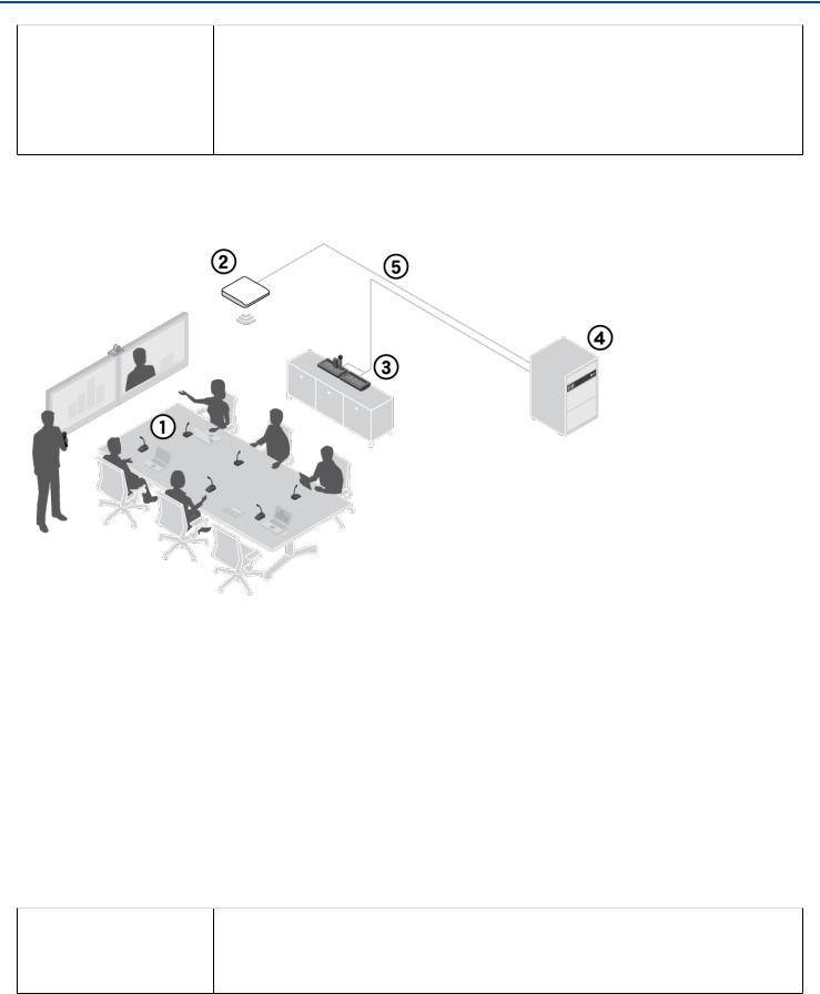
MXW Wireless System
Wireless Microphones
System processor and wireless transceiver
Microphone linking and charging station
Analog output device with gigabit network switch
Shielded Cat5e cables (not included)
Components of the MXW System
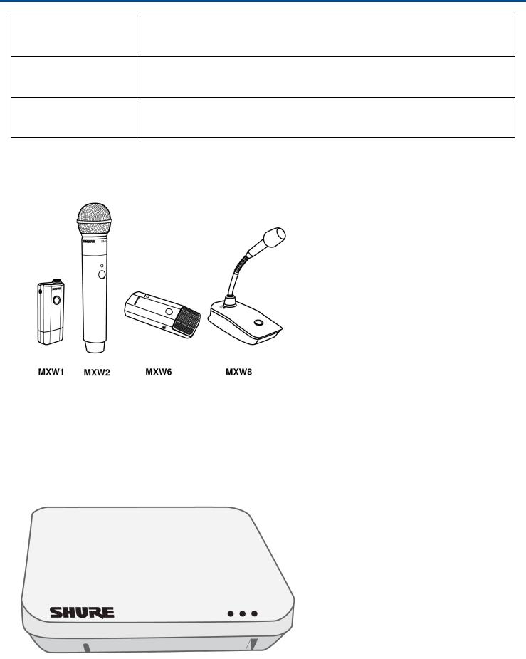
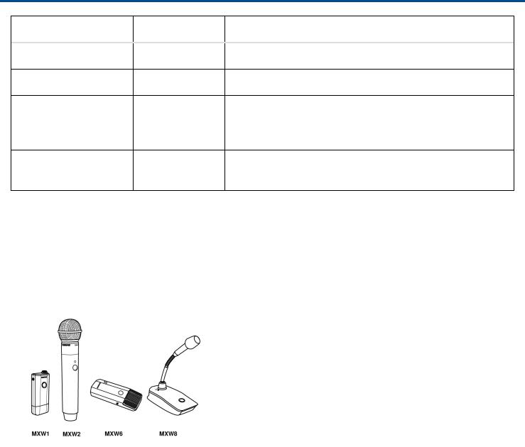
Microphone Transmitters
MXW microphones transmit an encrypted, wireless audio signal to the access point. Four form factors are avail able:
Hybrid Bodypack |
The bodypack secures to a belt or strap for hands-free, mobile communication. It |
(MXW1) |
features a TQG input for lavalier connection and an integrated omnidirectional mi |
|
crophone. |
3/103
Shure Incorporated
Handheld (MXW2) |
The handheld enables presenters to communicate using legendary Shure SM58, |
|
SM86, BETA58 and VP68 microphone cartridges. |
Boundary (MXW6/C, |
The boundary transmitter sits on a table or desk to transmit speech while discreetly |
MXW6/O) |
blending into any conference environment. |
Desktop Gooseneck |
The gooseneck base is compatible with 5, 10, and 15” Microflex gooseneck micro |
Base (MXW8) |
phones. |
The MXW1, MXW6, and MXW8 microphones include a headphone output for monitoring audio, such as a transla tion channel.
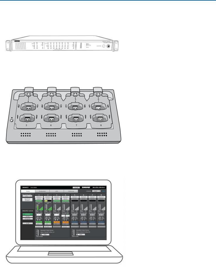
Access Point Transceiver (MXWAPT2, MXWAPT4, MXWAPT8)
The Access Point Transceiver (2, 4 and 8 channel units) mounts to a wall or ceiling to manage encrypted, wireless audio connections with microphones. As a system hub, it transports digital audio between the wireless micro phones and other Dante devices on the same network. The APT includes a webserver that hosts the MXW System control software, used for monitoring, configuration, and remote control of the system.
4/103
Shure Incorporated
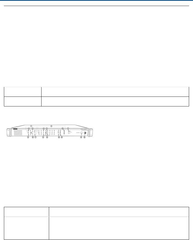
Audio Network Interface (MXWANI4, MXWANI8)
The Audio Network Interface (4 and 8 channel) is a Dante network device that provides analog audio input and outputs for the MXW system. It has a 4port Gigabit Ethernet switch that enables the connection of an MXW ac cess point, a computer and up to two MXW networked charging stations.
Networked Charging Station (MXWNCS2, MXWNCS4, MXWNCS8)
The Networked Charging Station (2, 4 and 8 slot varieties) is capable of simultaneous charging MXW micro phones. It also links microphones to access point channels and networks battery statistics to the control software.
Note: The MXWNCS2 does not work with the MXW8 gooseneck microphones.
MXW Control Software
The MXW control software offers comprehensive remote control of key setup, monitoring and management func tions. The software is accessible from any computer on the network, and opens in a web-browser using Adobe®Flash®.
5/103

Shure Incorporated
System Design and Technology
Technology Overview of the Audio Path
The MXW System combines Shure legendary audio quality with advanced digital networking technology. The fol lowing is an overview of the audio path:
Wireless Audio
The MXW transmitter converts speech into a digital signal that is transmitted wirelessly to the access point.
•Intelligent, automatic wireless audio management using the Digital Enhanced Cordless Telecommunications (DECT) framework
•Custom RF design enables higher audio quality and lower latency than most DECT systems
Digital Audio Network
The access point receives wireless audio from the microphones and distributes it to the audio network interface.
•Low latency, tight clock synchronization, and high Quality-of-Service (QoS) provide reliable audio transport.
•Digital audio is carried over Ethernet cables and standard IP equipment.
•Audio coexists safely on the same network as IT and control data, or can be configured to use a dedicated net work.
Analog Audio
The audio network interface converts network audio for each channel into analog outputs.
• Sends analog audio to a mixer, Digital Signal Processor (DSP), or teleconferencing device.
Forming Groups and Linking Microphones
Once all the MXW components are connected to the network, they can be associated into Groups from the Config uration tab of the control software. Each Access Point can form an association Group with one or two chargers (for Linking microphones) and one or two audio output devices (for routing audio to analog outputs). The microphones can then be placed in the charger and Linked to these access point channels.
Each Group is managed by a single access point. Microphones are Linked to channels in the access point, not to the charger that was used to Link them. This relationship persists until the microphones are reLinked or the ac cess point is reset.
Configurations: Managing Multiple Groups
Configurations allow multiple Groups to share the same preferences and global controls. When an additional Group is added to a Configuration page, a relationship is established across all devices in the configuration. The new Group will take on the settings of that configuration.
For specialized applications such as multiple room setup, several configurations can be created to independently control component Groups.
6/103
Shure Incorporated
Hardware Description
Audio Network Interface (ANI)
The ANI performs the following functions:
•Converts digital audio from the network into analog audio to connect to a sound reinforcement system or recording device
•Four-port gigabit switch can connect an entire MXW system (up to eight channels) and power the MXW access point
•Provides analog input(s) to route audio to the microphones for personal monitoring.
•Front-panel interface provides status indicators and access to basic system controls.
•Hosts an embedded web server that provides an interface for monitoring and control of the device.
Model Variations
MXWANI8 |
Eight channel outputs; two input channels |
MXWANI4 |
Four channel outputs; one input channel |
Front Panel
Input Channels
Adds analog line or auxlevel signals to the digital network. When the device is associated to an MXW Group, in puts are automatically routed to Linked microphone channels (Input A to channels 1-4; Input B to 5-8).
Output Channels
Converts digital network audio to an analog output for each channel. When associated to an MXW group, access point channels are automatically routed to the outputs of the ANI.
Channel Selector
Selects a channel to perform the following functions:
Action |
Function |
|
Single Press |
• |
Listen to that channel at the headphone jack |
|
• |
Display and adjust the channel output level and attenuation |
|
• |
Monitor output signal on the level meter |
7/103

Shure Incorporated
Action |
Function |
Press and Hold (3 sec Mute/unmute a channel. Mute is indicated by the mute LED. onds)
Selected Channel LED
Illuminates when a channel is selected.
Signal Strength LED (sig/clip)
Indicates audio signal strength for each channel:
•Green = Normal
•Amber = Strong
•Red = Clipping (to eliminate clipping, attenuate the signal level at the audio source)
Mute LED
Illuminates red when the channel output is muted (hold its channel select button for 3 seconds). A muted channel is still routed to the HEADPHONE jack for monitoring or troubleshooting.
Input Level Selector
Set the selected channel to lineor aux-level to match the input signal.
Output Level Selector
Set the selected channel to an output level that matches the connecting device:
•line: +4 dBu
•aux: -10 dBV
•mic: -30 dBV
Output Attenuation Control
Use the up/down buttons to attenuate the channel output from 0 dB (no attenuation) to -24 dB in 1 dB increments, and from -24 to -78 in 3 dB increments.
Level Meter
Displays a selected channel's audio level in dBFS. It is good practice to use -18 dBFS on the output meter as an approximation of 0 VU on an analog meter.
Hardware Status LEDs
Indicate the status of the hardware:
LED |
Color |
Status |
Power |
Green |
Unit is powered on. |
8/103
Shure Incorporated
LED |
Color |
Status |
Ethernet |
Green |
Connected to an Ethernet device. |
Network Audio |
Green |
All connected receive channels are OK (receiving digital audio as expected). |
|
Flashing |
One or more connected receive channels experiencing a subscription error |
|
Green |
or is unresolved (transmitting device is off, disconnected, renamed or has in |
|
|
correct network setting). |
|
Off |
No receive channels connected (routing has not been established). |
Lockout |
Red |
Front panel gain and mute controls are locked. The LED will blink when a |
|
|
button is pressed while the hardware is locked. |
Headphone Volume Knob
Adjusts the volume to the headphone output.
Headphone Output
1/4" (6.35 mm) output jack for monitoring audio going to and from the digital audio network.
Note: Audio is present only when the unit is connected to a digital audio network.
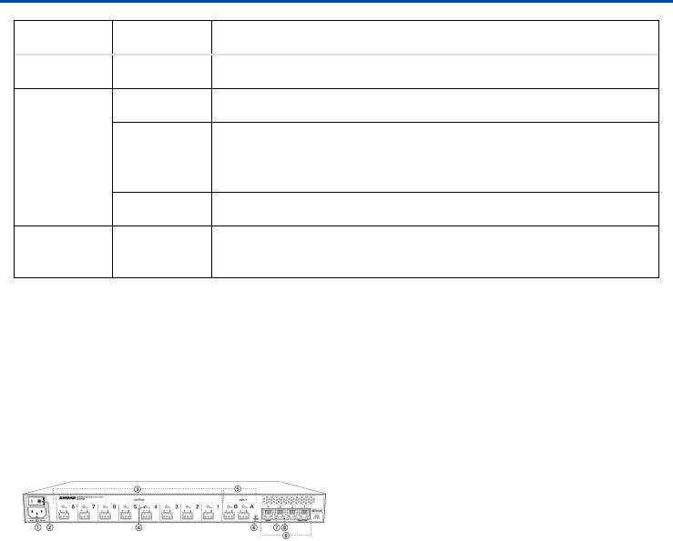
Back Panel
AC Power
IEC connector 100 - 240 V AC.
Power Switch
Powers the unit on or off.
Output Block Connectors (1-8)
Three-pin, low-voltage differential connector provides a line-, auxor mic-level analog output for each channel.
Chassis Ground (1-8)
Use to directly ground the cable shield to the chassis.
Input Block Connectors (A,B)
Three-pin, low-voltage differential input connector adds lineor aux-level analog signals to the digital network.
Note: This input is meant for balanced connection. If an unbalanced source is used, such as an IPOD or MP3 play er, only use pins 1 (signal) and 3 (ground) of the block connector. See Specifications sections for wiring diagrams.
9/103

Shure Incorporated
Reset Button
Press and hold the button for five seconds to reboot the device with factory default settings.
Ethernet Status LED (Green)
•Off = no network link
•On = network link established
•Flashing = network link active
Ethernet Link Speed LED (Amber)
•Off = 10/100 Mbps
•On = 1 Gbps (required for digital audio routing)
Network Interface
Four-port gigabit switch for connecting components together for a single MXW Group, or for connecting multiple devices to a larger digital audio network. The following is a description of each port:
Port |
Description |
Port 1 (PoE) |
Provides Power over Ethernet (PoE) for the Shure access point and functions as a standard |
|
gigabit port. |
Ports 2 and 3 |
Standard gigabit ports enable the connection of another MXW network, additional |
|
MXWANIs, a MXWNCS charging stations or an external control system. |
Port 4 (Uplink) • Normal mode (default): this port functions the same as ports 2 and 3.
•Uplink Mode: only transports control data. This mode blocks network audio and data for Shure Web Discovery Application, Dante Controller and Dante Virtual Soundcard.
Access Point Transceiver (APT)
The access point transceiver is the hub of the audio signal flow and manages the RF stability of each microphone in the group. The APT performs the following functions:
•Receives and decrypts wireless audio signals from microphones in the group
•Delivers the audio signal to the digital audio network and audio network interface (ANI)
•Hosts an embedded web server that provides access to the control software used to manage the MXW system
•Sends and receives control information (such as gain adjustment and link settings) between the components, MXW control software and 3rd party controllers.
•Transmits an encrypted audio signal to the microphone's headphone output for listening to translated audio or other external sources.
Model Variations
MXWAPT8 |
Eight-channel transceiver |
10/103
Shure Incorporated
MXWAPT4 |
Four-channel transceiver |
MXWAPT2 |
Two-channel transceiver |
Power LED
Illuminates green to indicate the presence of Power over Ethernet (PoE).
Network Audio LED
Color |
Status |
Green |
All routed receive channels are OK (receiving digital audio as expected). |
Flashing Green • One or more connected receive channels experiencing a subscription error or is unre solved (transmitting device is off, disconnected, renamed or has incorrect network set ting).
•Receiving an Identification signal from the control software (simultaneous flash with Link Status LED).
•The device is performing a spectrum scan (alternating flash with Link Status LED).
•Clock synchronization problem.
Off |
No receive channels connected (routing has not been established). |
Note: the network audio status can be monitored in detail from Dante Controller software.
Microphone Link Status LED
Color |
Status |
Green |
≥1 microphone is linked and powered on in the Active, Mute or Standby state. |
Off |
≥1 microphone is linked and is Off or in a nonnetworked charger. |
11/103
Shure Incorporated
Color |
Status |
Red |
No microphones have been linked. |
Flashing Red |
• Receiving an Identification signal from the control software (simultaneous flash with |
|
Network Audio LED). |
|
• The device is performing a spectrum scan (alternating flash with Network Audio |
|
LED). |
Reset Button
Press and hold the reset button for 10 seconds to reset the MXW system to factory default settings.
Note: The reset deletes group association and microphone links, and will reboot the device in DHCP mode.
Ethernet Port
Connect a shielded Cat5e (or higher) cable to a PoE source and the network.
Ethernet Status LED (Green)
•Off = no network link
•On = network link established
•Flashing = network link active
Ethernet Link Speed LED (Amber)
•Off = 10/100 Mbps
•On = 1 Gbps (required for proper MXW functionality)
Cable Routing Path
Provides a path for the Ethernet cable to enable a flush-mount to the ceiling or wall.
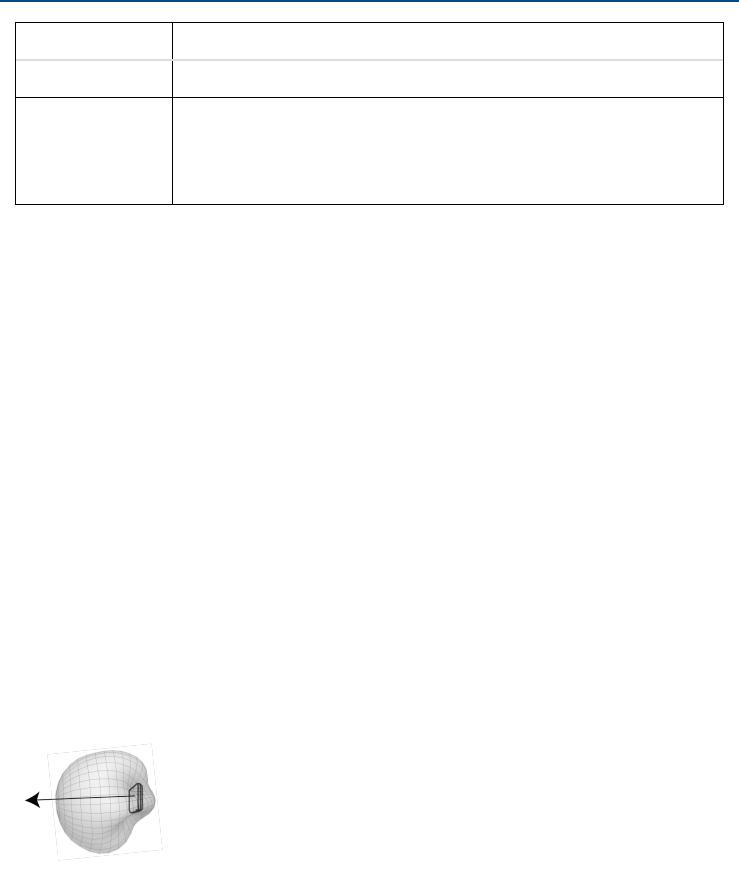
Directional Antennas
The access point contains multiple directional antennas to provide steady, reliable wireless communication with the microphones. It sends and receives the RF signal in a cardioid pattern with the greatest sensitivity toward the face of the device. Always aim this side toward the microphone coverage area.
Cardioid RF Pattern
12/103
Shure Incorporated
Networked Charger (NCS)
The MXW networked charging station enables battery charging and channel linking from a single location. When a charger is associated to a group, its channel slots are mapped to access point audio channels. Microphones can then be placed in the slots to Link to these channels.
Any microphone can recharge in any NCS, regardless of Group association or network connection. Caution:
When the Link button on an associated charger is pressed, all microphones in the charger will be mapped to chan nels on an access point. This will override any previously Linked microphones on those channels.
Model Variations
MXWNCS8 |
• |
Accepts eight boundary, bodypack, or handheld microphones |
|
• |
or four gooseneck bases |
MXWNCS4 |
• |
Accepts four boundary, bodypack, or handheld microphones |
|
• |
or two gooseneck bases |
MXWNCS2 |
• |
Accepts two boundary, bodypack, or handheld microphones. |
|
• |
MXW8 Gooseneck bases are not supported on this charger |
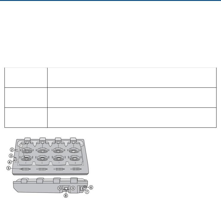
Charging Slots (USB 3.0 Type A)
Recharge and link microphones by connecting them to the USB slots on the charger. When the charger is associ ated to a group, the slots are mapped to access point channels (See Audio Channel Assignment for details).
Note: Any microphone can charge in any charger, regardless of Group association or network connection.
Power LED
Illuminates green when the unit is powered on.
Microphone Link LED
Indicates the status of the Linking procedure:
13/103

Shure Incorporated
Color |
Indicator |
Off (default) |
No Link has been initiated. |
Flashing Green |
Link procedure is in process. |
Green |
Microphones have been successfully linked to channels. |
Red |
Link procedure unsuccessful (RF issue, network failure, or microphones removed |
|
during procedure) |
Amber |
Link procedure cannot start because the station is not associated to a group. |
Flashing Red |
Link procedure has been locked from the control software. |
Microphone Link Button
Press and hold for 6 seconds to link all microphones in the charger to channels of the associated Access Point Transceiver.
Battery Status LEDs
Monitors the charge status of the connected microphone in increments of <10, 10, 25, 50, 75, 100% (see Batteries for more detail). Additionally, the five LEDs flash for several seconds when the microphone has been successfully linked to the channel.
Locking DC Power Supply
Secures the PS60 power supply to the input jack of the station.
Power Switch
Powers the unit on or off.
Ethernet Port
Connects to the MXW System network through an MXW Audio Network Interface or a switch using an Ethernet ca ble.
Ethernet Status LED (Green)
•Off = no network link.
•On = network link established.
•Flashing = network link active.
Ethernet Link Speed LED (Amber)
•Off = 10 Mbps
•On = 100 Mbps
14/103
Shure Incorporated
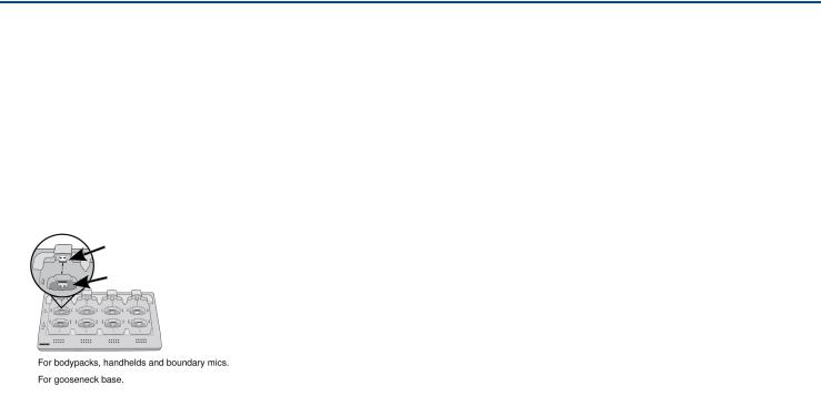
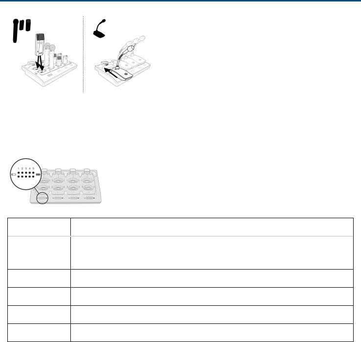
Connecting Microphones
Place a microphone in the charger by connecting it to one of the channel slots. The channels in the top row have two USB ports to accommodate different types of microphones. Do not attempt to connect to both USB ports at the same time.
Note: 2-channel chargers do not support gooseneck microphones.
•Handheld, boundary and bodypack: use the main vertical slots in the recessed bays.
•Gooseneck base: uses the top row's horizontal connectors.
Different Connectors for the Same Channel
Microphone Transmitters
Description
Power Button
MXW6, MXW8: Press and hold the dedicated power button for three seconds to turn the transmitter on or off.
MXW1, MXW2: Press and hold the Mute/Active button for five seconds to turn the transmitter on or off.
Mute/Active Button
Changes the audio status from Active to Mute, or Mute to Active. The button behavior for each transmitter type can be set independently from the Preferences tab. The following describes the function of each setting:
•Toggle: Press and release the button to change the status to Active or Mute.
•Push-to-talk: Hold button to pass audio.
•Push-to-mute: Hold button to mute the audio.
•Disabled: The button does not affect the audio.
Status LED
Indicates the transmitter's status. The color indicators for Mute and Active can be customized from the Preferences tab. See the Status LED table for the default LED behavior for MXW transmitters except the gooseneck light-ring models (MX405R/410R/415R).
Low Battery LED (Gooseneck and Boundary only)
15/103

Shure Incorporated
Color |
Status |
Off |
<5% battery runtime remains |
Solid Red |
>5% battery runtime remains |
Earphone Jack
1/8" (3.5 mm) jack for monitoring a return channel signal, such as translated audio. This audio is automatically routed from the input(s) of the Audio Network Interface (Input A to channels 1 - 4; Input B to channels 5 - 8).
Note: Not featured on the MXW2 handheld transmitter.
Charge Connector (USB 3.0 Type A)
Connects to the NCS charger slot or to the USB Charger.
Handheld Cartridge
MXW2 transmitter is compatible with the following cartridge types: SM58, Beta 58, SM86, VP68.
Gooseneck Microphone
The gooseneck base is compatible with 5, 10, and 15” Microflex gooseneck microphones.
TQG Connector
The MXW hybrid bodypack has a TQG connector for an external lavalier or headset microphone.
Internal Microphone
The bodypack transmitter has an internal, omnidirectional microphone that can be set to automatically engage when not connected to a lavalier microphone.
Status LED Table
Status |
LED |
Description |
Active |
Green |
Ready to pass audio to network. |
Mute |
Red |
Audio is muted. |
Standby |
Red Pulsing (long |
Audio is muted and the transmitter is in a hibernation state to |
|
off, short on) |
conserve the battery. |
Identify |
Flashing Yellow |
The Identify button has been pressed from the control soft |
|
|
ware. |
Out of RF Coverage |
Red Pulsing |
The transmitter is out of the RF coverage range to the linked |
Range |
(short on/off) |
access point. |
16/103
Shure Incorporated
Status |
LED |
Description |
Charging |
Off |
The transmitter is charging. |
Battery Statistics Reset |
Flashing Yellow |
Battery statistics have been reset for the transmitter. |
Two microphones trying |
Red Pulsing (long |
Only one microphone for each audio channel can be active at |
to connect to same au |
on, short off) |
a time. |
dio channel |
|
|
Off |
Off |
No connection to the network. The transmitter must be turned |
|
|
on using the power button on the mic. |
Microphone Transmitters
MXW microphones transmit an encrypted, wireless audio signal to the access point. Four form factors are avail able:
Hybrid Bodypack (MXW1)
The bodypack secures to a belt or strap for hands-free, mobile communication. It features a TQG input for lavalier microphone connection and an integrated omnidirectional microphone.
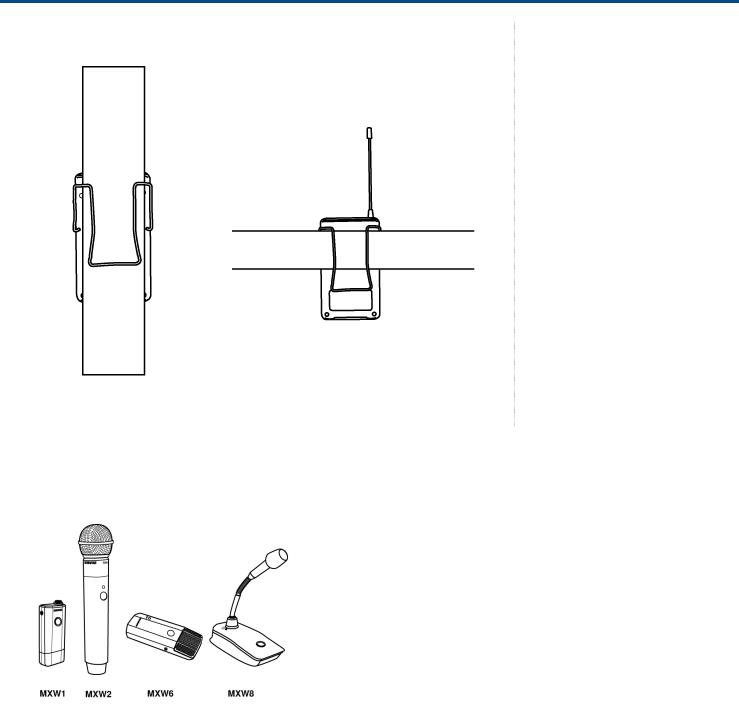
Wearing the Bodypack Transmitter
•Clip the transmitter to a belt or pocket.
•For best results, the belt should be pressed against the base of the clip.
17/103
Shure Incorporated
Handheld (MXW2)
The handheld enables presenters to communicate using legendary Shure SM58, SM86, BETA58 and VP68 micro phone cartridges.
18/103
Shure Incorporated
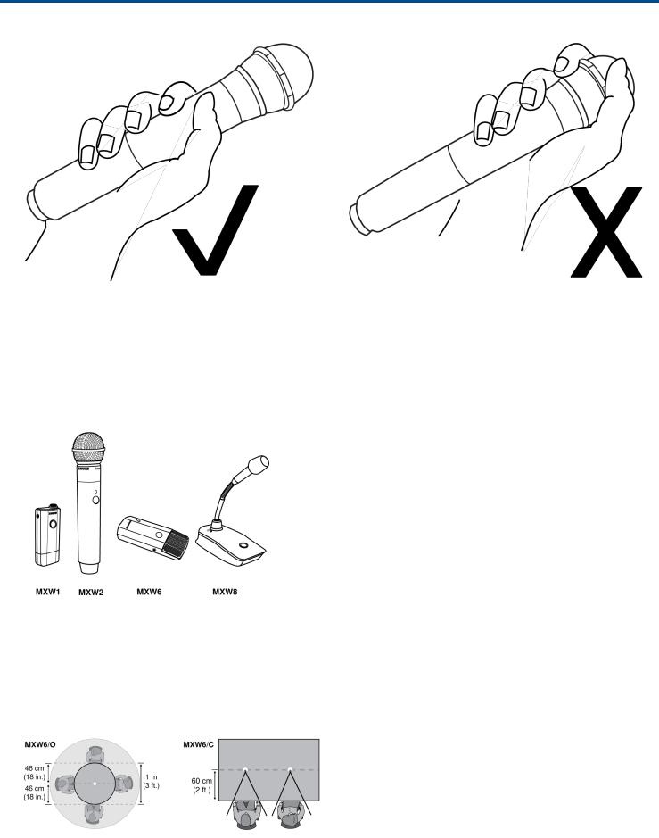
Correct Microphone Placement
•Hold the microphone within 12 inches from the sound source. For a warmer sound with increased bass pres ence, move the microphone closer.
•Do not cover grille with hand.
Boundary (MXW6/C, MXW6/O)
The boundary transmitter sits on a table or desk to transmit speech while discreetly blending into any conference environment. Cardioid and omnidirectional versions are available.
Microphone Placement
For best low-frequency response and rejection of background noise, place the microphone on a large, flat surface, such as a floor, table, or lectern.
To reduce reverberance, avoid reflective surfaces above or to the side of the microphone, such as beveled sides of pulpits or overhanging shelves.
19/103
Shure Incorporated
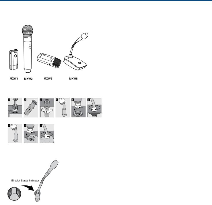
Desktop Gooseneck Base (MXW8)
The gooseneck base is compatible with 5, 10, and 15” Microflex gooseneck microphones.
Microphone Types
Insert Microphone into Base
MX405, MX410 & MX415
Bi-color Status Indicator
20/103
Shure Incorporated
MX405R, MX410R & MX415R
Light Ring
Rechargeable Batteries
MXW lithiumion rechargeable batteries use advanced chemistry that maximizes transmitter runtime. Power man agement from the control software provides detailed visibility to critical battery parameters such as charge status, battery capacity, and cycle count.
Batteries charge to 50% capacity in one hour and to full capacity in two hours using the MXW Networked Charging Station.
Models
Microphone Type |
Battery Model |
MXW1 bodypack |
SB901A |
MXW6 boundary |
|
MXW8 gooseneck base |
|
MXW2 handheld |
SB902A |
Networked Charging Station (NCS)
Slide the transmitter into the charging slot until it secures into place. The charge LEDs illuminate when the charge cycle begins. Regardless of Group association or network connection, any microphone can recharge in any NCS.
21/103
Shure Incorporated
•Handheld, boundary and bodypack: use the main vertical slots in the recessed bays.
•Gooseneck base: uses the top row's horizontal connectors. (Not included on two-channel chargers).
Charge Status LEDs
Each charger channel has a row of LEDs that illuminate to indicate the microphone battery charge level:
LED |
% Battery Charge |
1• Flashing: <10%
• Solid: >10%
2 |
>25% |
3 |
>50% |
4 |
>75% |
5 |
>95% |
NCS Energy Efficient Mode
Operate the charger in a lowenergy mode to reduce power consumption. In this mode, only one LED indicator illu minates per channel after powering on.
To change to the mode:
1.Open the MXW control software to the Utility page.
2.Open the Device Properties window for the charging station.
3.Select the Energy Efficient Mode check-box.
USB Charger
The USB Charger (SBC-USB) can connect to an MXW transmitter to provide power during operation.
22/103
Shure Incorporated
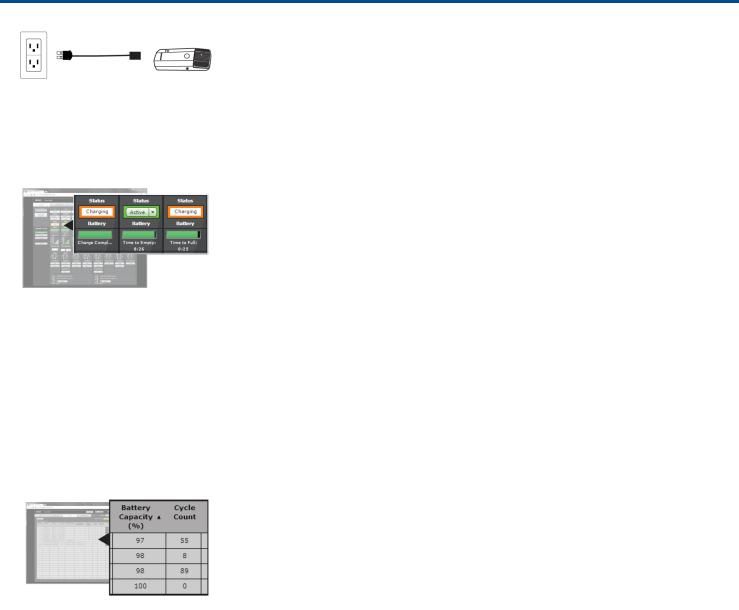
Battery Statistics on Control Software
The MXW control software is used to manage battery information. Use the Monitor tab to view battery charging status:
Monitoring Battery Charge Status
In the Charging Station
Displays the remaining time until the microphone battery is fully charged.
During Use
Displays the remaining battery runtime of the microphone.
For battery health statistics, use the Utility tab:
Battery Statistics
Battery Capacity
The microphone battery's percentage of charge capacity as compared to a new battery.
Cycle Count
Number of charge cycles logged by the battery.
Reset the Microphone Battery Statistics
After installing a new battery, reset the battery health statistics that are stored in the microphone.
1.Place the transmitter with a new battery into a charging slot. You can use any powered MXW charging station.
2.Press and hold the mute button on the microphone until its LED flashes (~10 seconds).
Caution: Securely hold the microphone while pressing the button to avoid damaging the USB ports on the charging station.
23/103

Shure Incorporated
Maximizing Battery Life
While the rechargeable LiIon batteries for MXW transmitters are designed to last up to 9 hours on a charge, vari ance in battery health and usecase may result in significant differences in battery runtime. Specifically, consisten cy and overall runtime decrease with the number of charge cycles. Battery health of 80% or less is an indicator that a battery is nearing or at the end of its designated life cycle and should be replaced. Health percentage and number of charge cycles are available from > .
The MXW system's secondary link slots allow you to prepare alternate microphones to swap in if battery levels get low, to ensure variable battery runtime does not cause audio interruptions. However, the following system adjust ments can help get the most runtime out of your batteries.
External LED Control
Having LEDs constantly indicate the microphone state can use a significant amount of battery power. Setting transmitters to External LED Control disables the built-in LED except when activated by external commands via the TCPI (third-party control interface). Maximize battery runtime by disabling the LED completely, or by setting the LED to only indicate when the microphone is not in its usual use state.
LED control is set from MXW control software > Preferences tab .
High Density Mode
High Density (HD) mode reallocates system resources to create additional channels when needed. In applications where latency, back-channel audio monitoring, and filter control aren't major considerations, switching to HD mode can also provide up to an hour of additional battery runtime.
Density mode is set from MXW control software > Utility tab > [desired APT] > Edit .
Use-Case Scenarios
To estimate runtime on older batteries, find your microphone and the conditions that most closely match your set up. Runtime (hours) was calculated using batteries at 80% health.
System Settings |
|
Runtime (hours) |
|
|
|
LED |
Density Mode |
MXW1 |
MXW2 |
MXW6 |
MXW8 |
External |
HD |
8 |
15 |
8 |
8 |
External |
SD |
7 |
14 |
7 |
7 |
Internal |
HD |
7 |
14 |
8 |
7 |
Internal |
SD |
6 |
12 |
7 |
6 |
Tip: If additional runtime is needed, make sure the RF Power is at the lowest setting for the size of the room. RF power is set from > .
Battery Replacement
Lithium Ion Batteries experience a linear reduction in capacity. Shure recommends establishing a battery replace ment schedule customized to the client requirements and replacing batteries when the capacity is no longer ac ceptable.
24/103

Shure Incorporated
MXW1, MXW6, MXW8 Battery Replacement
1.Unscrew and open the battery door on the bottom of the transmitter.
2.Remove battery by gently disconnecting the battery connector from the transmitter.
3.Connect the replacement battery's connector to the transmitter.
4.Replace the battery with the label facing out.
5.Close the door and tighten the screw.
6.Dispose of batteries properly. Check with your local vendor for proper disposal of used batteries.
MXW2 Battery Replacement
1.Unscrew the two screws at the bottom of the transmitter handle.
2.Unscrew and remove the microphone head.
3.Remove the retention clip and gently pull out the battery frame.
4.Unscrew the three screws that fasten the battery door to the frame. Remove the battery door.
5.Replace the old battery with a new one.
6.Replace the battery door and tighten the screws.
7.Gently slide the battery frame back into the transmitter.
8.Replace the retention clip to secure the battery frame in the transmitter.
9.Replace the microphone head. Make sure it is secure.
10.Replace the two screws on the bottom of the transmitter handle.
11.Dispose of batteries properly. Check with your local vendor for proper disposal of used batteries.
Installation
Additional Equipment
Network Cables |
Use shielded Cat5e (or higher) Ethernet cables, limiting cable runs to 100 meters |
|
|
maximum between network devices. |
|
Audio Cables |
Reference the hardware kit user guide supplied with the MXW Audio Network Inter |
|
|
face to assemble audio cables to the connectors. |
|
Gigabit DHCP Router |
For systems with more than one APT, a DHCP router is recommended to connect |
|
(systems with >1 APT) |
equipment. Ensure that it meets the following requirements: |
|
|
• |
Gigabit ports |
|
• |
Provides Class 0 PoE with at least 6.5W (for powering the MXWAPT) |
|
• |
Quality of Service (QoS) with 4 queues |
|
• |
Diffserv (DSCP) QoS, with strict priority |
|
• |
If the router features Energy Efficient Ethernet (or Green Ethernet), ensure it is |
|
|
disabled from the ports dedicated for the MXW system. |
|
• Recommended: A managed switch to provide detailed information about the op |
|
|
|
eration of each network link: port speed, error counters, bandwidth used, etc. |
25/103
Shure Incorporated
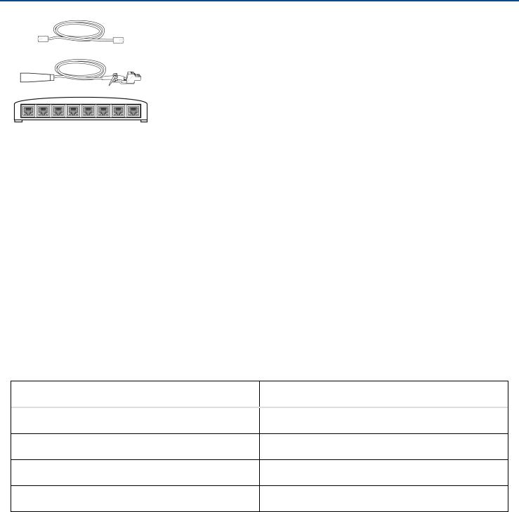
Connecting MXW Components
MXW components are connected using Ethernet cables and a switch. For a small system with a single access point, the MXW Audio Network Interface functions as the switch. For systems with more than one access point, an additional gigabit switch is required for connecting all the components together.
Requirements:
•Use shielded Cat 5e (or higher) Ethernet cables. Limit cable runs to ≤100 m between devices.
•Use Gigabit networking equipment between network audio devices (required for systems with >1 access point).
•Ensure MXW components are on the same firmware version.
•Ensure MXW components and the PC are on the same network and set to the same subnet.
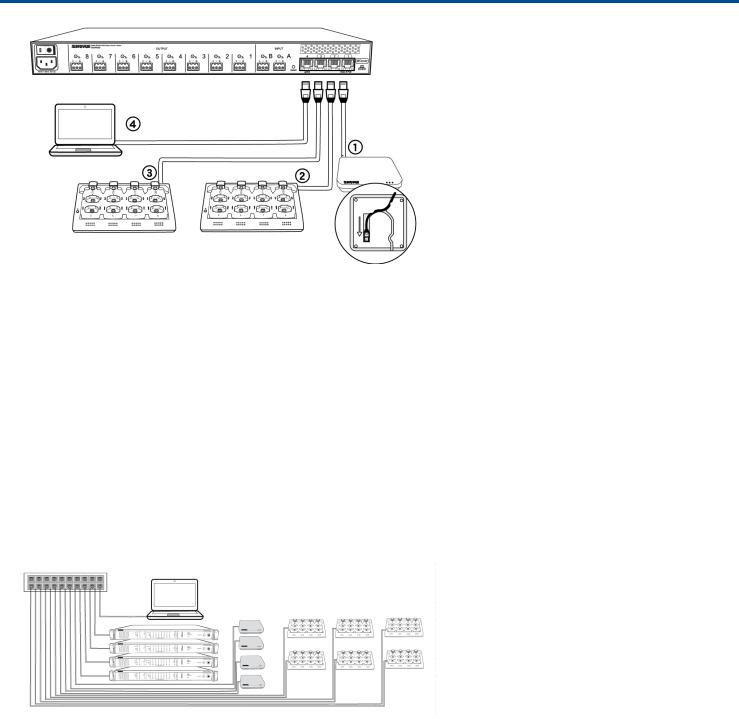
Single Group System (1 Access Point)
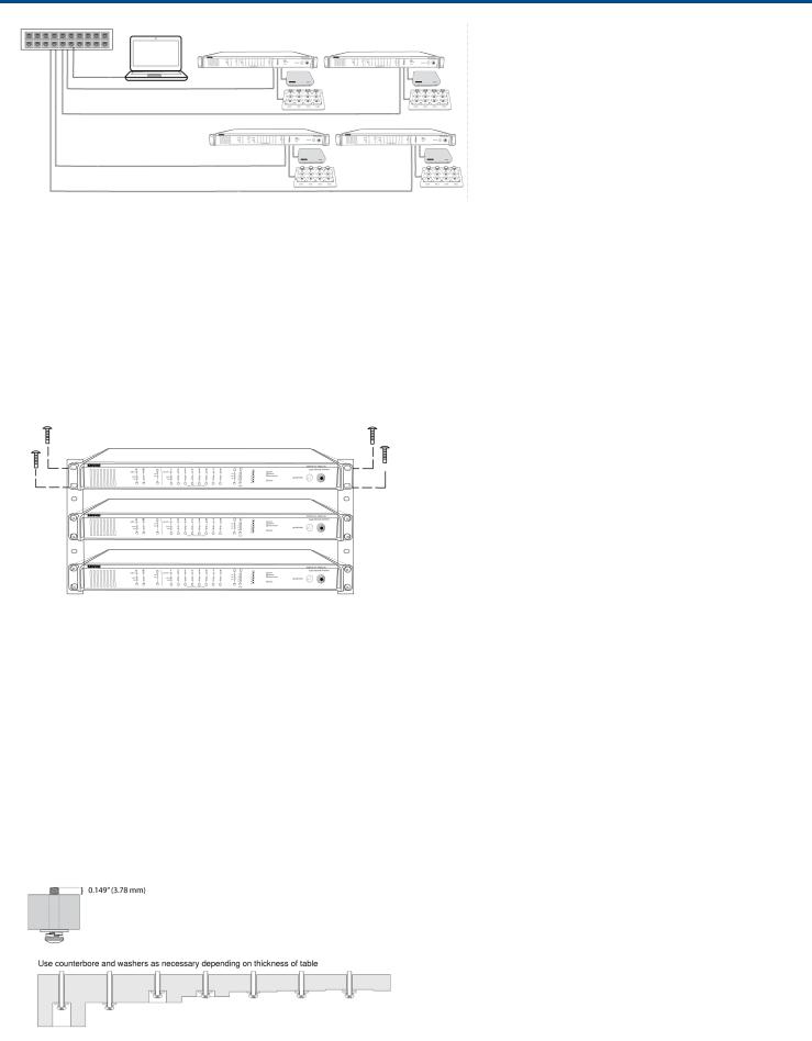
When the system is limited to a single group (up to eight channels), use the MXW Audio Network Interface fourport switch for connecting MXW components. Connect the computer, access point and up to two chargers to the MXW interface according to the table and diagram:
Audio Network Interface Port |
To Component |
Port 1 (PoE) |
Access Point Transceiver (APT) |
Port 2 |
Networked Charging Station (NCS) |
Port 3 |
(Optional) Additional NCS |
Port 4* |
Computer |
*When Port 4 is set to Uplink mode, Shure Discovery Application support is restricted.
26/103
Shure Incorporated
Multiple Group System (>1 Access Point)
When an installation requires more than eight channels, additional MXW components can be connected to expand the system. A gigabit router is required to connect all components to the same network. The following are several topologies for multiple group systems.
Use the Spectrum Scanner to ensure that there is sufficient RF availability for the installation.
Large Single-Room Installation
1.Power on the DHCP-enabled router.
2.Connect the router to a computer.
3.Connect each APT to a Power over Ethernet (PoE)-enabled port on the router. Use a PoE inserter if the router does not provide it.
4.Connect each ANI to the router.
5.Connect chargers to the ANI ports, or to the router.
Local System Star Setup
To minimize cabling, MXW components can use the Audio Network Interface as a local switch that connects to a shared network.
1.Power on the DHCP-enabled router.
2.Connect the router to a computer.
3.Connect the router to Port 2, 3, or 4 on the Audio Network Interface
4.Connect the Access Point Transceiver to the Port 1 of the Audio Network Interface.
5.Connect the Network Charging Station(s) to an open port(s) on the Audio Network Interface.
6.Repeat steps 2 - 4 for additional equipment.
27/103
Shure Incorporated
Rack Installation
Rackmount the device using the screws and washers supplied in the Hardware Kit. Follow these general best practices when installing equipment in a rack:
•Ambient temperature of the rack should not exceed specified operating temperature range of the device.
•Keep fan inlet and side air vents clear from obstructions and provide adequate space for airflow within the rack.
•When possible, provide 1 RU of empty space between each device.
Securing the Charging Station
This kit provides washers and screws for securing a charging tray to a table or other surface. Use two kits for the NCS8. Please refer to the NCS mounting template for screw hole placement.
Important: The top of the screw must extend exactly / (0.149) inches (3.78 mm) above the surface (about 4½ threads).
•Use the screws that best fit the thickness of the table.
•Use a lock washer and flat washer for each screw.
•If necessary, counterbore the screw head or add additional flat washers.
28/103
Shure Incorporated
Required Thread Exposure
Use counterbore and washers as necessary depending on thickness of table
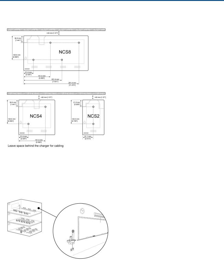
NCS Mounting Template
Two-Channel Charger Wall Mount
The two-channel charger includes a wall-mount to provide quick microphone access and storage in a classroom or conference room.
NCS2 Secures to a Classroom Wall
Tip: Paint the mount to match the wall for a less obtrusive installation.
29/103
Shure Incorporated
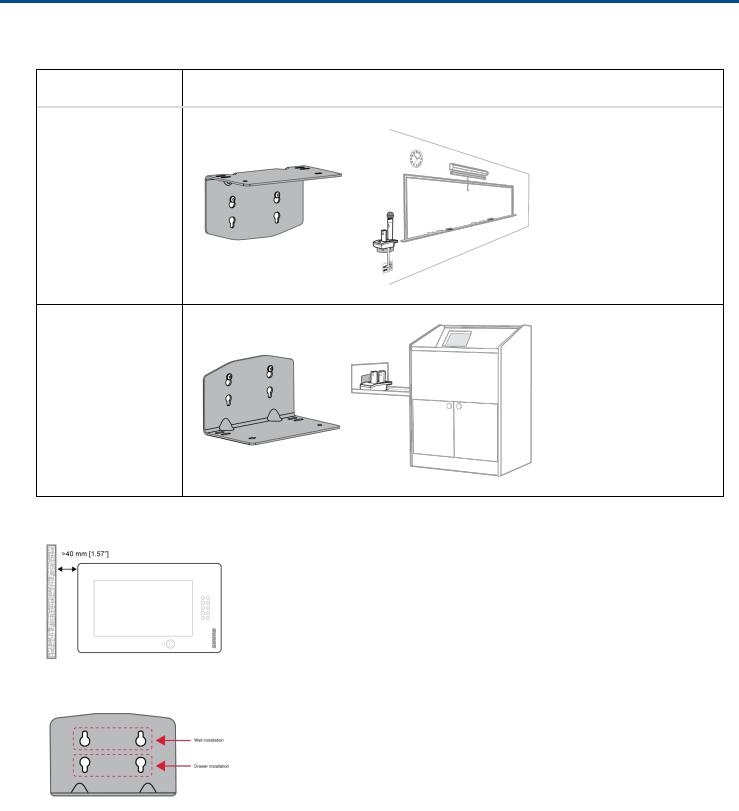
Installation
1. Determine the orientation and placement of the mount.
Placement Orientation
Wall
Drawer or tray
2. Leave room around the mount for cabling to the charging station.
3. Attach the mount to the wall. Use one set of screw holes depending on the orientation of the mount.
Mount Screw Holes
4. Align the charger on the mount and secure with the screws.
30/103
 Loading...