


Shure Incorporated
222 Hartrey Avenue
Evanston IL 60202-3696 U.S.A.
UHF Wireless System
SERVICE MANUAL CHANGE NOTICE
U2 HAND-HELD TRANSMITTER
Changes and corrections have been made to the Service Manual for the U2 UHF Hand-Held Transmitter. These changes will make it easier to repair the transmitters. To update your Service Manual, remove the pages identified in the tables below and replace them with the pages attached to this Change Notice. Note that there are no changes to pages not specifically identified in the tables below.
U2 SERVICE MANUAL REVISION HISTORY
Release |
Part Number |
Date Code |
|
|
|
Original |
25A1022 |
QE |
|
|
|
Revision 1 |
25B1022 |
SA |
|
|
|
Revision 2 |
25C1022 |
TD |
|
|
|
Revision 3 |
25C1022 |
AG |
|
|
|
CHANGES EFFECTIVE JULY 2, 2001
REMOVE |
INSERT |
these pages from the |
these Revised pages into the |
U2 Service Manual |
U2 Service Manual |
|
|
22 |
22 |
|
|
|
|
|
E2000 Shure Incorporated |
Printed in U.S.A. |
|
25–1022–2 (AG) |
|
|
Service Manual
U2 Hand-Held UHF Transmitter
General
Characteristics
The Shure Model U2 Hand-Held UHF Transmitter is a microprocessor controlled microphone-transmitter operating in the 774 to 862 MHz frequency range. This product is intended for use in highend installed sound, rental, and concert sound applications. Different frequency variations are available in various countries.
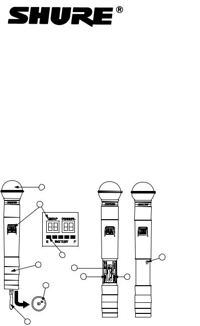
Controls and Indicators
1 |
|
|
2 |
|
|
|
3 |
10 |
|
|
|
|
|
GAIN |
45 |
7 |
|
|
|
|
|
8 |
9 |
5 |
|
|
ON |
|
|
OFF |
|
|
|
6 |
|
|
1. |
Grille |
6. |
Antenna |
2. |
Programmable Display |
7. |
Battery Compartment |
3. |
Battery Fuel Gauge |
8. |
MODE Button |
4. |
Battery Cover |
9. |
SET Button |
5. |
ON/OFF Switch |
10. |
Audio Gain Control |
Figure 1. U2 Transmitter Controls and Indicators
Service Note: Shure recommends that all service procedures be performed by a Factory-Authorized Service Center or that the product be returned directly to Shure Brothers Inc.
Licensing: Operation may require a user license. Frequency or power-output modifications may violate this product’s approvals. Contact your country’s communications authorities.
E1999, Shure Incorporated |
Printed in U.S.A. |
25B1022 (AG) |
|
Shure U2 Hand-Held UHF Transmitter
Circuit Description
Audio Section
Audio enters L248, an inductor used as an rf choke. The signal is ac-coupled through C201 into a 26 dB user-adjustable gain stage around U201B. This gain stage is externally accessible to the user. C249, C250, and C209 protect the preamplifier and bias circuits from rf interference. R212 and R241 set up a half-supply bias, and R238 sets the ac input impedance.
The amplified audio signal is then passed through a pre-emphasis network before entering the compression stage. R230, R202, and C203 set up two corners for the pre-emphasis network. The pre-emphasis boosts the high frequencies before transmission.
This network feeds an NE575 compandor, U203, which utilizes an external amplifier U204B. The compandor performs 2:1 logarithmic compression of the audio signal. Additionally, the pre-emphasis network plays a role in setting the hinge point (0 dB gain) of the compandor.
Transistors Q211 and Q207, along with crystal Y202, form the tone key oscillator circuit. This circuit provides a stable, continuous 32.768 kHz sine wave. Transistor Q201 buffers the tone key signal before it is added to the audio signal.
The tone key signal is used in the receiver to provide audio output only when the tone key signal is present in the transmitted signal; therefore, if the tone key or the transmitter is turned off, the receiver will be muted. The tone key squelch eliminates receiver noise associated with loss of a carrier. Q206 acts as a switch for toggling the tone key ON/ OFF. It is controlled by the microprocessor. R286 allows for the tone key amplitude level to be set.
The tone key circuit is powered via U210B. This is a dc amplifier used to multiply the 3V battery voltage up to 4.5 V (gain = 1.5). As the battery voltage drops, the tone key supply voltage drops, decreasing the amplitude of the oscillator. This is used to detect low battery in the receiver. (This feature was eliminated for JB models.)
The tone key signal, along with the processed audio signal, is then fed to a summing amplifier U204A. R231 and R234 set up a half-supply bias. R207, at the output of the summing amplifier, is used to help prevent spurious oscillations from the operational amplifier. After passing ac-coupling capacitor C213, the signal is fed to the rf module.
Rf Section
Processed audio enters an internal potentiometer R227, which is adjusted for 45 kHz deviation (100% modulation) with a -7.2 dBV 1 kHz tone at the output of the front audio stage (pin 1 of U201). (On JB models, R227 is adjusted for 5 kHz deviation with a –67.2 dBV, 1 kHz tone injected into the mic input.) The audio is then fed to the tuning voltage pin of the voltage controlled oscillator (VCO) and modulates the carrier directly. The use of a phase locked loop (PLL) frequency-synthesized system eliminates the need for multiplier stages, resulting in a much higher degree of spectral purity. The VCO is shielded to prevent interfer-
Circuit Description |
2 |
25B1022 (AG) |
Shure U2 Hand-Held UHF Transmitter
ence from external rf fields. Regulated 5 Vdc power from the dc/dc converter ensures frequency stability even if the battery voltage drops.
The VCO is capable of tuning from 782 to 810 MHz with a 1 to 4 V tuning voltage range. At the output of VCO U206, the rf signal splits into two paths. The output of the VCO is coupled by C207 to the frequency control pin of synthesizer U205.
The synthesizer’s internal circuitry divides the signal as necessary to the desired reference frequency of 125 kHz. The synthesizer contains a quartz-controlled reference oscillator circuit operating from a 4.0 MHz crystal, Y203, that is adjusted by means of trimmer VC201.
The transmitter output frequency is user-selectable in pre-set increments. The size of the increment and the overall frequency range depend on the model (KK, JB, MB, MC, MD, etc.). Frequency selection is made via microprocessor U104, which interfaces with the user through the mode/select switches.
The output of the synthesizer is a series of pulses which are integrated by a passive loop filter, R226, C231, R251, C237, R243, and C257, to produce a control voltage signal. The control voltage signal is then connected to the VCO through amplifier U210A which is used to isolate the PLL filter from the audio modulation signals.
The VCO output is also coupled to an rf power resistive pad consisting of R255, R256, R257, R258, and an LC-matching network containing C270, L202, and C217. The rf power amplifier, a dual gate MESFET, Q203, is fixed tuned, and configured as a common source device. Amplifier stability is obtained through resistive loading on input R237. The output of Q203 contains a low-pass matching network, L207, and LC-type low pass filter, LP201, providing a high degree of spectral purity. The output of the low-pass filter feeds a microwave isolator that reduces the production of reverse third-order intermodulation products.
The transmitter is capable of delivering +10 dBm (10 mW), maximum to the 50 Ω helical antenna. During transmitter power up and frequency selection, the rf power is muted by bringing the base of Q209 high. This provides approximately 45 dB rf attenuation until the PLL has locked.
The transmitter rf is then unmuted by bringing the base of Q209 low. During transmitter power off conditions, voltage is first removed from the VCO by bringing the base of Q208 high. In this way, the transmitter carrier signal is not allowed to drift off frequency during power on or power off conditions.
U2 Display Board
The Display Board consists of following circuitry blocks:
Microcontroller Section
The microcontroller section consists of microcontroller U104 and the liquid crystal display (LCD). The microcontroller has an on-board LCD driver. R104, R105, and R107 supply the microcontroller with the LCD drive voltage for a 4-plex drive.
The LCD indicates the UHF frequency group and channel, and also has a battery fuel gauge. A 4.000 MHz oscillator, Y101, provides the
25B1022 (AG) |
3 |
Circuit Description |
Shure U2 Hand-Held UHF Transmitter
operating frequency to the microcontroller. The oscillator circuit includes C102, C103, R106. R108. U105, R113, and C107 form the reset circuit. U105 is the reset IC that resets U104 microcontroller if the 5 Vdc normal operating voltage falls below 3.5 Vdc. R112 is the pull-up resistor for the U104 programming voltage pin.
Memory Section
The memory section consists of U101, a non–volatile EEPRAM chip that stores current transmitter settings and has the mapping of the compatible groups and channels.
Battery Management Section
The battery management section consists of comparator U103. It is used to measure the effective battery voltage, with reference to +5 Vdc, by measuring the time taken to charge capacitor C105 to a reference threshold of 0.1 VDE ± 0.01 Vdc. The battery is checked approximately every five seconds. Comparator U103 alternately charges C105 with +5 Vdc reference and then the battery voltage (DPLUS signal). The microcontroller calculates the battery voltage by comparing the time difference to charge C105, up to a reference threshold of 0.1 Vdc ± 0.01 Vdc, with the +5 Vdc reference voltage and the battery voltage.
User Interface Section
The user interface section consists of power, MODE, and SET switches. The LCD provides the user with feedback for all switch operations.
Circuit Description |
4 |
25B1022 (AG) |

Shure U2 Hand-Held UHF Transmitter
Preliminary Tests
Test Component Locations
TOP
BOTTOM
DIGITAL DISPLAY BOARD
R227 location for G and later board versions.
TOP
R227 location for F and earlier board versions.
BOTTOM
RF-AUDIO BOARD
Figure 2. Test Component Locations
25B1022 (AG) |
5 |
Preliminary Tests |
Shure U2 Hand-Held UHF Transmitter
Listening Test
Before completely disassembling the transmitter, operate it to determine whether it is functioning normally and try to duplicate the reported malfunction. Refer to the User Guide for operating instructions, troubleshooting, and specifications.
Review any customer complaint or request, and focus the listening test on any reported problem. The following, more extensive, functional tests require partial disassembly.
Functional Tests
Refer to the Disassembly section to partially disassemble the transmitter for the following functional tests.
Use dc blocks at all rf outputs to protect test equipment.
Use a U4 receiver for the following functional tests.
Test Set-Up
1.Dc voltages are present at most rf test points. Use dc blocks to protect the test equipment, if necessary.
2.Insert two fresh AA batteries into the U2 battery nest.
3.Connect the audio analyzer to the microphone via the microphone test head.
Rf Power
1.Attach a U4 antenna to the spectrum analyzer.
2.Turn the U2 on and hold it very close to the antenna. Move the U2 up and down to maximize power on the spectrum analyzer.
3.Verify that output power is greater than 3 dBm.
Current Drain
1.Apply 3.0 Vdc to the battery terminals.
2.Connect the amp meter between the positive (+) battery lead and the positive (+) battery terminal of the U2 transmitter.
3.Verify that the current drain is less than 110 mA.
Preliminary Tests |
6 |
25B1022 (AG) |
Shure U2 Hand-Held UHF Transmitter
Frequency Response
Values between board versions may vary slightly; the following values are typical values.
1.With the transmitter set to minimum gain, apply 100 mVrms at 1 kHz to its input.
If you have a version with a 6 dB pad (JB model), apply 200 mVrms at 1 kHz.
2.Connect the audio analyzer’s input to the unbalanced output of the U4 receiver.
3.Make sure the receiver volume control is set to maximum.
4.With respect to the 1 kHz level, measure –8.5 dBu ± 2 dB.
5.Change the frequency to 100 Hz and verify that the measurement from the U4 unbalanced output is within ± 3.0 dB with
respect to the 1 kHz level.
6.Change the frequency to 10 kHz and verify that the measurement from the U4 unbalanced output is within ± 1.5 dB with
respect to the 1 kHz level.
25B1022 (AG) |
7 |
Preliminary Tests |
Shure U2 Hand-Held UHF Transmitter
Notes
This page intentionally left blank.
Notes |
8 |
25B1022 (AG) |
Shure U2 Hand-Held UHF Transmitter
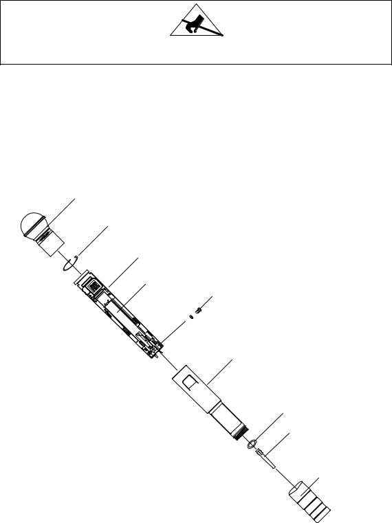
Disassembly and Assembly
ATTENTION
Observe precautions when handling this static-sensitive device.
1.Refer to Figure 2 and remove the microphone head from the U2.
2.Remove the retaining ring from inside the top of the case, using a pair of needle-nosed pliers.
3.Remove the screw located beneath the battery cup.
4.Slide the circuit board assembly out by pushing up on the antenna.
5.After completing all repairs, slide the circuit boards back into the case; then reinstall the retaining ring, screw and microphone head.
MICROPHONE
HEAD
RETAINING RING
PRINTED CIRCUIT BOARD ASSEMBLY
BATTERY NEST
RF GROUND
SCREW
CASE
CONDUCTIVE WASHER
ANTENNA
 “O” RING
BATTERY
CUP
Figure 3. U2 Transmitter Disassembly and Assembly
25B1022 (AG) |
9 |
Disassembly and Assembly |
 Loading...