


Main Menu
Shure Brothers Incorporated
222 Hartrey Avenue
Evanston IL 60202-3696 U.S.A.
Model DFR11EQ User Guide
DFR11EQ
Digital Feedback Reducer and Graphic Equalizer With Software Interface for Windows*
1996, Shure Brothers Inc. |
Printed in U.S.A |
27A8523 (PJ) |

Main Menu
TABLE OF CONTENTS
INTRODUCTION . . . . . . . . . . . . . . . . . . . . . . . . . . . . . . . . . . . . . . . . . . . . . . . . . . . . . . . . . . . . . . . . . . . . . . . . . . . . . . . . . |
2 |
Features . . . . . . . . . . . . . . . . . . . . . . . . . . . . . . . . . . . . . . . . . . . . . . . . . . . . . . . . . . . . . . . . . . . . . . . . . . . . . . . . . . . . 2 Added Features When Interfaced with a Personal Computer . . . . . . . . . . . . . . . . . . . . . . . . . . . . . . . . . . . . . . . 2
THE DFR11EQ . . . . . . . . . . . . . . . . . . . . . . . . . . . . . . . . . . . . . . . . . . . . . . . . . . . . . . . . . . . . . . . . . . . . . . . . . . . . . . . . . . . 3
Overview . . . . . . . . . . . . . . . . . . . . . . . . . . . . . . . . . . . . . . . . . . . . . . . . . . . . . . . . . . . . . . . . . . . . . . . . . . . . . . . . . . . . 3 DFR11EQ Theory . . . . . . . . . . . . . . . . . . . . . . . . . . . . . . . . . . . . . . . . . . . . . . . . . . . . . . . . . . . . . . . . . . . . . . . . . . . . 5 Setup for Feedback Control . . . . . . . . . . . . . . . . . . . . . . . . . . . . . . . . . . . . . . . . . . . . . . . . . . . . . . . . . . . . . . . . . . . . 7 Connecting the DFR11EQ in a Sound System . . . . . . . . . . . . . . . . . . . . . . . . . . . . . . . . . . . . . . . . . . . . . . . . . . . . 8
COMPUTER INTERFACE . . . . . . . . . . . . . . . . . . . . . . . . . . . . . . . . . . . . . . . . . . . . . . . . . . . . . . . . . . . . . . . . . . . . . . . . |
10 |
Overview . . . . . . . . . . . . . . . . . . . . . . . . . . . . . . . . . . . . . . . . . . . . . . . . . . . . . . . . . . . . . . . . . . . . . . . . . . . . . . . . . . . 10
Software Functions . . . . . . . . . . . . . . . . . . . . . . . . . . . . . . . . . . . . . . . . . . . . . . . . . . . . . . . . . . . . . . . . . . . . . . . . . . 12
Using the Feedback Reducer Panel . . . . . . . . . . . . . . . . . . . . . . . . . . . . . . . . . . . . . . . . . . . . . . . . . . . . . . . . . . . . 13
Using the Graphic Equalizer . . . . . . . . . . . . . . . . . . . . . . . . . . . . . . . . . . . . . . . . . . . . . . . . . . . . . . . . . . . . . . . . . . 14
Viewing Response Curves . . . . . . . . . . . . . . . . . . . . . . . . . . . . . . . . . . . . . . . . . . . . . . . . . . . . . . . . . . . . . . . . . . . . 15
Exiting the DFR11EQ Application . . . . . . . . . . . . . . . . . . . . . . . . . . . . . . . . . . . . . . . . . . . . . . . . . . . . . . . . . . . . . . 15
Accessing Connected DFR11EQs . . . . . . . . . . . . . . . . . . . . . . . . . . . . . . . . . . . . . . . . . . . . . . . . . . . . . . . . . . . . . 16
DFR11EQ Settings . . . . . . . . . . . . . . . . . . . . . . . . . . . . . . . . . . . . . . . . . . . . . . . . . . . . . . . . . . . . . . . . . . . . . . . . . . 17
Scenes . . . . . . . . . . . . . . . . . . . . . . . . . . . . . . . . . . . . . . . . . . . . . . . . . . . . . . . . . . . . . . . . . . . . . . . . . . . . . . . . . . . . . 18
APPENDICES . . . . . . . . . . . . . . . . . . . . . . . . . . . . . . . . . . . . . . . . . . . . . . . . . . . . . . . . . . . . . . . . . . . . . . . . . . . . . . . . . . |
19 |
Appendix A. Specifications . . . . . . . . . . . . . . . . . . . . . . . . . . . . . . . . . . . . . . . . . . . . . . . . . . . . . . . . . . . . . . . . . . . . 19 Appendix B. Rack Mounting the DFR11EQ . . . . . . . . . . . . . . . . . . . . . . . . . . . . . . . . . . . . . . . . . . . . . . . . . . . . . 20 Appendix C. Connectors and Cables . . . . . . . . . . . . . . . . . . . . . . . . . . . . . . . . . . . . . . . . . . . . . . . . . . . . . . . . . . . 21 Appendix D. Warranty . . . . . . . . . . . . . . . . . . . . . . . . . . . . . . . . . . . . . . . . . . . . . . . . . . . . . . . . . . . . . . . . . . . . . . . . 25
*Trademark Notifications
Shure is a registered trademark of Shure Brothers, Inc. Windows is a registered trademark of Microsoft Corporation. Crystal is a trademark of Crystal Semiconductor Corporation. Motorola is a registered trademark of Motorola, Inc. IBM is a registered trademark of the IBM Corporation.
1
Main Menu
INTRODUCTION
The Shure Model DFR11EQ is a single channel signal processor that combines a feedback reducer and graphic equalizer in a single, half-rack enclosure. The DFR11EQ is designed to be placed in a sound reinforcement signal path to automatically detect and control acoustical feedback and equalize overall sound system response. The DFR11EQ is designed for installed sound reinforcement applications: theater, conference rooms, meeting halls, etc. The DFR11EQ is also an effective setup tool for controlling major feedback modes in live music applications.
The feedback reducer of the DFR11EQ automatically inserts narrow notch filters at detected feedback frequencies. These notch filters stop a sound system from feeding back, but are narrow enough so their effect on audio quality is minimized. The feedback detection algorithm constantly searches for feedback, with or without the presence of program audio. The feedback reducer functions on its own or under external computer control.
The graphic equalizer of the DFR11EQ is made up of thirty 1/3-octave, constant Q filters and adjustable high pass and low pass filters. The graphic equalizer can be accessed via computer control with the supplied Windows* interface software.
Features
Adaptive Notch Filter algorithm (patent pending) which automatically detects feedback and deploys up to 10 narrow band notch filters.
Crystal* 20-bit A/D and D/A converters (Analog-to-Digital, Digital-to-Analog) for 104 dB dynamic range.
48 kHz sampling rate for flat response to 20 kHz.
1/2 rack space chassis allows rack mounting of one or two units in a single rack space with no sagging or bending.
Shure Link Interface allows multiple units to be programmed with a single computer.
No internal batteries. Settings and DSP program stored in internal EEPROM chip.
Electronically balanced input with combination 1/4-in. and XLR connector. Can be used with balanced or unbalanced outputs.
Independently driven, cross-coupled, balanced 1/4-in. and XLR outputs. Can be used with balanced or unbalanced inputs, without signal loss.
+4 dBu/±10 dBV DIP-switch-selectable input and output levels.
Motorola* DSP56009 processor engine with full 24-bit internal processing.
RS-232 interface for external computer control and firmware updates.
Internal linear power supply switchable between 120 and 240 Vac eliminates the need for a cumbersome external power supply.
Meets UL, CSA, VDE, and CE requirements for safety.
Solid state bypass eliminates unreliable mechanical relays and switches.
Added Features When Interfaced with a Personal Computer
Tamper-proof, constant-Q, 30-band, 1/3-octave graphic equalizer. Can boost up to 6 dB or cut 12 dB for each band.
Adjustable 12 dB/octave high pass and low pass filtering.
Front/back panel lockout control.
Response Curve Viewing. Displays frequency response of the feedback reducer, graphic equalizer, or both.
Numerical display of active feedback filter frequency and depth.
Storage of multiple scenes to floppy or hard disk.
2
Main Menu
THE DFR11EQ
Overview
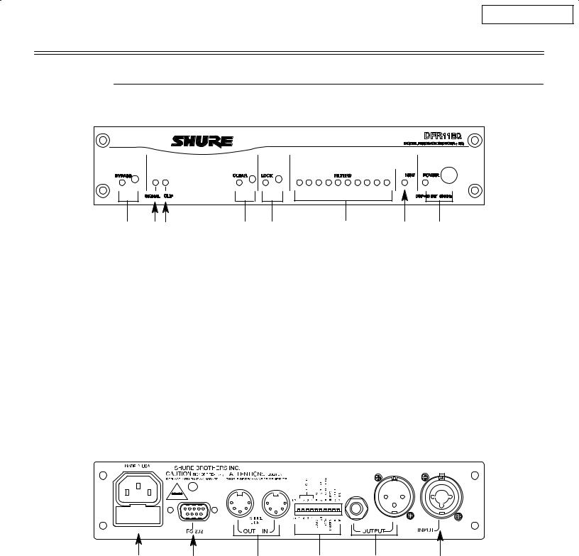
Front Panel
|
|
|
|
|
BYPASS Button and LED. Press this button to suspend feedback reducer operation and remove filters from the audio path. Does not affect the graphic equalizer. When the LED illuminates, the feedback reducer is bypassed.
SIGNAL LED. Illuminates when input signal is present. Intensity varies with input signal level.
CLIP LED. Illuminates when the input signal is within 6 dB of clipping.
CLEAR Filters Button and LED. Press this recessed button to reset all the feedback filters. Clears filters even if Lock Filters is enabled. LED illuminates as the button is pressed.
LOCK Filters Button and LED. Press this button to lock the filters at their current values. When the LED is on, the unit will not change or add any feedback filters.
FILTERS LEDs (10). Indicate when individual feedback filters are active. When a filter changes or is added, the LED flashes, then stays on.
NEW Filter LED. Flashes in unison with the feedback filter LEDs when the detector is deploying a new feedback filter or changing an existing one.
POWER Switch and LED. Press this button to turn the power on. LED illuminates when unit is powered on. When the power is off, the unit is bypassed automatically.
Back
Power Connector with Integral Fuse. Connects to AC power. The fuse is located in the drawer below the connector.
9-Pin RS-232 Port. Connects the unit to a computer. For use with DFR11EQ software and for DSP firmware upgrades.
Shure Link Interface. Allows linking of up to 16 DFR11EQs which may be accessed by computer.
DIP Switches. See DIP Switches.
Output ConnectorÐ1/4-Inch & XLR. Active, cross-coupled, balanced outputs can be used with balanced or unbalanced inputs. Can be switched
between +4 dBu/±10 dBV line-level operation by DIP switch. 1/4-Inch and XLR are driven independently and either can be balanced or unbalanced without affecting the other.
Input ConnectorÐCombined XLR and 1/4-Inch.
Active balanced input can be used with balanced or unbalanced outputs. Can be switched between +4 dBu/±10 dBV line-level operation by DIP switch.
3
Main Menu
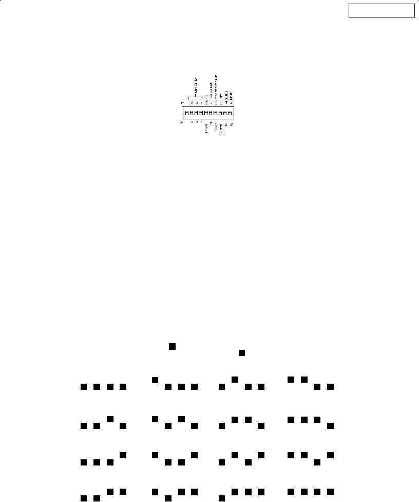
DIP Switches
The DIP switches located on the rear panel are used for adapting the unit to the sound system requirements. Switches 5 through 10 change other available options, see the table below.
DIP |
FUNCTION |
POSITION |
|
SWITCH |
|
|
|
|
UP |
DOWN |
|
|
|
||
|
|
|
|
1±4 |
Device ID |
see below |
see below |
|
|
|
|
5 |
Filter Bandwidth Select |
High Q |
Low Q |
|
Determines the Q of the feedback filter. |
1/10-octave |
1/10-octave |
|
|
narrows as it deepens |
widens as it deepens |
|
|
|
|
6 |
Graphic Equalizer Defeat |
EQ On |
EQ Off |
|
Bypasses the graphic equalizer. |
|
|
|
|
|
|
7 |
Front Panel Lockout |
Unlock |
Lock |
|
Disables the front panel controls, |
Front panel buttons |
Front panel buttons |
|
except the power switch. Protects |
operational |
inactive |
|
current settings from tampering. |
|
|
|
|
|
|
8 |
unused |
Ð |
Ð |
|
|
|
|
9 |
Output Level |
+4 dBu |
±10 dBV |
|
|
|
|
10 |
Input Level |
+4 dBu |
±10 dBV |
|
|
|
|
Shure Link Device ID
When multiple DFR11EQ's are linked, each one is assigned a Link Device ID, 0 through 15. DIP switches 1 through 4 on the rear panel are used to set the Link Device ID. To change the Device ID, align the switches according to the illustrations below. The unit comes factory preset to Device ID 15.
SWITCH UP |
SWITCH DOWN |
||||
|
|
|
|
|
|
|
|
|
|
|
|
|
|
|
|
|
|
|
DEVICE ID |
0 |
|
|
|
DEVICE ID |
1 |
|
|
|
DEVICE ID |
2 |
|
|
|
DEVICE ID |
3 |
|
|
|||||||||||||||||
|
|
|
|
|
|
|
|
|
|
|
|
|
|
|
|
|
|
|
|
|
|
|
|
|
|
|
|
|
|
|
|
|
|
|
|
|
|
|
|
|
|
|
|
|
|
|
|
|
|
|
|
|
|
|
|
|
|
|
|
|
|
|
|
|
|
|
|
|
|
|
|
|
|
|
|
|
|
|
|
|
|
|
|
|
|
|
|
|
|
|
|
|
|
|
|
|
|
|
|
|
|
|
|
|
|
|
|
|
|
|
|
1 |
2 |
3 |
4 |
|
1 |
2 |
3 |
4 |
|
|
1 |
2 |
3 |
4 |
|
1 |
2 |
3 |
4 |
|
|||||||||||||||
|
|
|
|
|
|
|
|
|
|
|
|
|
|
|
|
|
|
|
|
|||||||||||||||||
|
DEVICE ID |
4 |
|
|
|
DEVICE ID |
5 |
|
|
|
DEVICE ID |
6 |
|
|
|
DEVICE ID |
7 |
|
|
|||||||||||||||||
|
|
|
|
|
|
|
|
|
|
|
|
|
|
|
|
|
|
|
|
|
|
|
|
|
|
|
|
|
|
|
|
|
|
|||
|
|
|
|
|
|
|
|
|
|
|
|
|
|
|
|
|
|
|
|
|
|
|
|
|
|
|
|
|
|
|
|
|
|
|
|
|
|
|
|
|
|
|
|
|
|
|
|
|
|
|
|
|
|
|
|
|
|
|
|
|
|
|
|
|
|
|
|
|
|
|
|
|
|
|
1 |
2 |
3 |
4 |
|
1 |
2 |
3 |
4 |
|
|
1 |
2 |
3 |
4 |
|
1 |
2 |
3 |
4 |
|
|||||||||||||||
|
|
|
|
|
|
|
|
|
|
|
|
|
|
|
|
|
|
|
|
|||||||||||||||||
|
DEVICE ID |
8 |
|
|
|
DEVICE ID |
9 |
|
|
|
DEVICE ID |
10 |
|
|
|
DEVICE ID |
11 |
|
|
|||||||||||||||||
|
|
|
|
|
|
|
|
|
|
|
|
|
|
|
|
|
|
|
|
|
|
|||||||||||||||
|
|
|
|
|
|
|
|
|
|
|
|
|
|
|
|
|
|
|
|
|
|
|
|
|
|
|
|
|
|
|
|
|
|
|
|
|
|
|
|
|
|
|
|
|
|
|
|
|
|
|
|
|
|
|
|
|
|
|
|
|
|
|
|
|
|
|
|
|
|
|
|
|
|
|
|
|
|
|
|
|
|
|
|
|
|
|
|
|
|
|
|
|
|
|
|
|
|
|
|
|
|
|
|
|
|
|
|
|
|
|
|
1 |
2 |
3 |
4 |
|
1 |
2 |
3 |
4 |
|
|
1 |
2 |
3 |
4 |
|
1 |
2 |
3 |
4 |
|
|||||||||||||||
|
|
|
|
|
|
|
|
|
|
|
|
|
|
|
|
|
|
|
|
|||||||||||||||||
|
DEVICE ID |
12 |
|
|
|
DEVICE ID |
13 |
|
|
|
DEVICE ID |
14 |
|
|
|
DEVICE ID |
15 |
|
|
|||||||||||||||||
|
|
|
|
|
|
|
|
|
|
|
|
|
|
|
|
|
|
|
|
|
|
|
|
|
|
|
|
|
|
|
|
|
|
|||
|
|
|
|
|
|
|
|
|
|
|
|
|
|
|
|
|
|
|
|
|
|
|
|
|
|
|
|
|
|
|
|
|
|
|
|
|
|
|
|
|
|
|
|
|
|
|
|
|
|
|
|
|
|
|
|
|
|
|
|
|
|
|
|
|
|
|
|
|
|
|
|
|
|
|
1 |
2 |
3 |
4 |
|
1 |
2 |
3 |
4 |
|
|
1 |
2 |
3 |
4 |
|
1 |
2 |
3 |
4 |
|
|||||||||||||||
|
|
|
|
|
|
|
|
|
|
|
|
|
|
|
|
|
|
|
|
|
|
|
|
|
|
|
|
|
|
|
|
|
|
|
|
|
4
Main Menu
DFR11EQ Theory
Feedback and DFR11EQ Operation
When acoustical feedback occurs in a sound system, it is because the gain of the system is too high. Since no sound system (microphones, loudspeakers, room acoustics, etc.) has an absolutely flat frequency response, feedback will occur at specific frequencies before others; these are the frequencies with the most gain. If the gain at only these specific frequencies is lowered, then the system can operate with more overall gain before it feeds back, without a perceptible difference in tonal quality. This is the operating principle of the DFR11EQ.
At the heart of the DFR11EQ is a very powerful algorithm that can accurately and quickly discriminate between feedback and non-feedback sounds (speech and music). When this algorithm detects feedback, it smoothly inserts a ±3 dB, 1/10-octave notch filter into the audio path to reduce the gain at the frequency which is feeding back. If the feedback does not stop, the filter depth is increased in 3 dB increments (up to ±18 dB) until the feedback stops.
After the DFR11EQ stops the feedback at one frequency, the sound system may start feeding back at another frequency. In this case, the DFR11EQ inserts another notch filter into the audio path at the new frequency. The DFR11EQ can insert a total of 10 notch filters to reduce feedback.
DFR11EQ Limitations
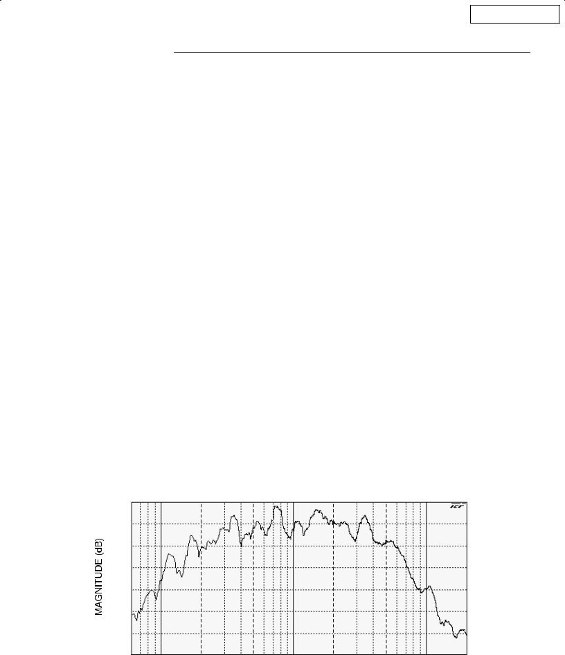
The DFR11EQ (or any other notch filter system) cannot entirely eliminate feedback in a sound system, it can only help to reduce it. In a typical system, a point of diminishing returns is reached after 4 to 8 notch filters are set. This is because generally there are only a few dominant frequency response peaks above the response of the entire system (see diagram below). The DFR11EQ works very well controlling these peaks. The user can expect a 6 to 9 dB improvement of gain-before-feedback in a typical system. However, if the system has too much overall gain, then all of the frequencies have too much gain; instead of trying to notch out all of the frequencies, better results will be obtained by lowering the gain of the system. If the system still has insufficient gain, then other changes must be made to the sound system such as different microphone or loudspeaker placement. There are several excellent publications which delve deeper into the issue of feedback and sound systems, including: Acoustic Feedback ± How to Avoid It, Vivian Capel, Bernard Babani Publishing, ISBN 0±85934±255±7; Sound Reinforcement Handbook, Gary Davis and Ralph Jones, Hal Leonard Publishing, ISBN 0±88188±900±8; Sound System Engineering, Don and Carolyn Davis, Howard W. Sams and Co., ISBN 0±672±21857±7; ªUnderstanding Sound System Designº, Rick Frank, Shure Brothers, # AL1174; ªBasic Handbook of Feedback Reductionº, Matt Anderson and Jon Tatooles, Shure Brothers, # AL 1280.
100
95
90
85
80
75
70
65
60 |
100 |
200 |
500 |
1000 |
2000 |
5000 |
10000 |
20000 |
FREQUENCY (Hz)
5

Main Menu
Fixed and Dynamic Notch Filters
The DFR11EQ can control the notch filters as either dynamic or fixed. The DFR11EQ's 10 notch filters are factory preset as 5 fixed and 5 dynamic filters. There is no difference between dynamic and fixed filters until all 10 filters have been set. After all 10 notch filters are set and a new feedback frequency is detected, the DFR11EQ will remove the oldest set dynamic filter and re-deploy it at the new feedback frequency. The fixed filters remain unchanged. However, if feedback occurs at the same frequency as an existing dynamic or fixed filter, the existing filter will deepen. The number of fixed versus dynamic filters can be adjusted via the DFR11EQ's Windows interface.
An example of a system that would benefit from more fixed filters and less dynamic filters is one that has fixed microphone and loudspeaker locations. In this type of system, the most dominant frequencies of feedback are defined by the room dimensions and the microphone and loudspeaker placement, and will not change appreciably. However, feedback can still occur, for instance, when someone's hand or head approaches a microphone. A good setting for this type of system would be 7 fixed filters for the non-changing feedback frequencies, and 3 dynamic filters to catch the feedback frequencies caused by the talker.
On the other hand, more dynamic than fixed filters would be appropriate in a system that has several non-stationary wireless microphones. Eight or even all 10 filters could be set to dynamic in this type of system to obtain maximum feedback protection. As every application is different, some experimentation is recommended to get the best results from a given sound system.
High Q vs. Low Q Filters
The DFR11EQ offers two selections for the shape of the 1/10-octave notch filters. The first, High Q, is the default setting. A High Q filter's width stays very narrow as the filter depth is increased. This attenuates the minimum amount of signal possible to ensure system stability, while maintaining excellent sound quality. This setting is appropriate for most applications.
The Low Q setting maintains the filter's shape as it is deepened, so the width of the filter effectively widens as the depth increases. Using this setting attenuates the signal more, producing a greater system stability than the High Q setting, but with slightly diminished sound quality. This setting is appropriate for systems such as a speech-only PA where stability is an absolute must, but the sound quality can be compromised a bit.
Filter Locking
The feedback filters can be locked from the front panel of the unit or from the computer interface. When locked, new filters will not be deployed and existing filters will not be deepened, even if feedback is detected. The DFR11EQ's algorithm is designed to accurately differentiate feedback from non-feedback sounds such as speech. However, certain sounds such as electric guitar feedback or test tones, which sound like feedback, may cause the algorithm to deploy an unwanted filter.
For most applications, locking the feedback filters is unnecessary. As a rule of thumb, if the application will contain material which sounds similar to acoustic feedback, then it is prudent to lock the filters after ringing out the sound system.
6

Main Menu
Setup for Feedback Control
The DFR11EQ will operate stand-alone as a feedback reducer. However, when connected to a personal computer running the supplied DFR11EQ software, additional options are available. See Computer Interface for details.
There are two basic ways in which to set-up the DFR11EQ: The ªRing Outº method and the ªInsurance Policyº method. Both are valid for different situations. The ªRing Outº method is a preemptive measure in which the system gain is raised beyond the normal setting to deliberately make the system feed back. The DFR11EQ will then set its filters, and the system gain is then reduced slightly, and the system is stable and useable. This set-up method is primarily used for systems which are operated near the feedback point and need an extra margin of stability.
For the ªInsurance Policyº method, the DFR11EQ is simply installed in the sound system, but filters are not set prior to use. The DFR11EQ adds extra insurance against feedback: the system is not expected to feed back, but if it does, the DFR11EQ is there to catch it. This set-up method is used for systems which already have sufficient gain-before-feedback, but need protection from the occasional stray feedback which can occur due to non-stationary microphones or user-adjustable gain controls.
Setup
1.Connect the DFR11EQ in the desired signal path location. See Connecting the Unit In a Sound System.
2.Set the input and output level DIP switches to the appropriate settings for the sensitivities of the connected equipment.
WARNING: Other equipment may potentially be damaged after DFR11EQ power off if the DFR11EQ input is set to +4 and the output is set to ±10. If the DFR11EQ input is set to +4 and the output is set to ±10, then the DFR11EQ is acting as an attenuator, lowering the signal to the proper level for the power amplifier. If the DFR11EQ is turned off, this attenuation is bypassed and the power amplifier will receive too strong a signal. It is recommended that you avoid using this setting.
3.Set the system gain to minimum, and power up all of the equipment.
4.Slowly raise the gain of the system, and set the gain of each microphone to achieve the desired level.
5.The red CLIP LED should illuminate only on the highest signal peaks. If it illuminates more frequently, check to see that the input level switch is set properly. If it is, lower the level of the signal coming into the DFR11EQ.
6.At this point it is highly recommended to equalize the sound system with the DFR11EQ's built±in graphic equalizer (see Computer Interface) or an external equalizer. The DFR11EQ's feedback reducer is more effective on a well±equalized sound system.
Ringing Out the System (ªRing Outº method only)
1.If necessary, clear any notch filters in the DFR11EQ by pressing the CLEAR button. Turn off the BYPASS and LOCK LEDs if they are not already off.
2.Slowly raise the gain of the signal going through the DFR11EQ. When feedback occurs, the DFR11EQ will insert a filter deep enough to stop the system from feeding back.
3.Repeat step 2 until all fixed filters are set. (There are 5 fixed filters, unless changed by the user via the computer interface.)
4.Lower the gain by 3 to 6 dB to stabilize the sound system.
Power Down
When power is removed from the DFR11EQ, all settings (graphic equalizer, feedback filters, button states) are automatically saved to the DFR11EQ's internal non-volatile memory. On power up, all settings are recalled automatically.
7
Main Menu
Connecting the DFR11EQ in a Sound System
The DFR11EQ should be placed where an equalizer would be in a signal path Ð it should be the final piece of equipment a sound signal passes through before going to a power amplifier. Other signal processors (for example, delay or reverb effects devices) should be placed before the DFR11EQ along the signal path.
The following four diagrams show typical connections. Because of its utility and flexibility, the DFR11EQ can be connected in a large variety of different setups to benefit a sound system.
NOTE: See Appendix C. for descriptions of all cable and connection wiring.
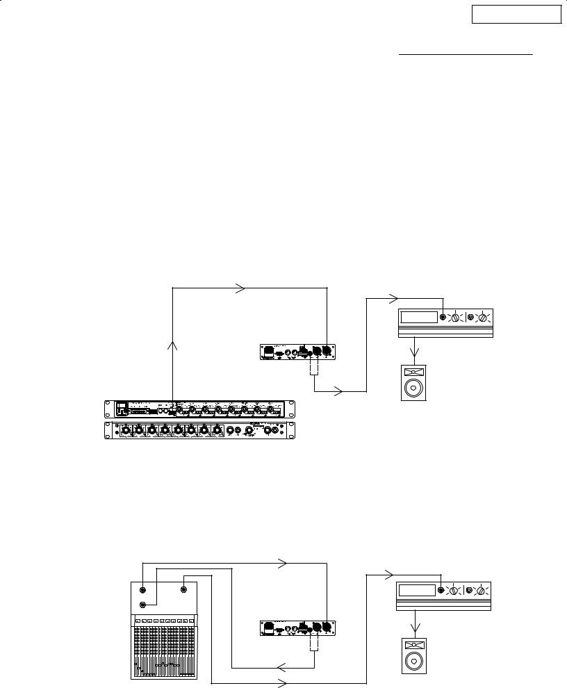
Between the Mixer Main Output and the Power Amplifier
The DFR11EQ is most commonly placed between the main output of a mixer and the input of a power amplifier, after any dynamics control processors. At the main output, the unit will affect all input channels. This setup is ideal for using the DFR11EQ as a feedback reducer and as a graphic equalizer.
|
LINE |
DFR11EQ |
LINE IN |
|
POWER AMPLIFIER |
LINE OUT |
|
LINE OUT |
|
|
LOUDSPEAKER |
MIXER |
|
At a Subgroup Insert
When using a multiple bus mixer, the DFR11EQ can be connected to a single subgroup insert. The unit will affect only the channels associated with that subgroup: the other channels will remain unaffected.
|
|
LINE IN |
SUB SEND |
|
|
|
LINE |
|
SUB RETURN |
OUT |
|
|
MAIN |
LINE IN |
|
DFR11EQ |
|
|
|
POWER AMPLIFIER |
|
LINE OUT |
|
|
MIXER |
LOUDSPEAKER |
|
|
8
 Loading...